EP2940828A1 - A mobile device and power providing equipment for wireless charging - Google Patents
A mobile device and power providing equipment for wireless charging Download PDFInfo
- Publication number
- EP2940828A1 EP2940828A1 EP15165710.3A EP15165710A EP2940828A1 EP 2940828 A1 EP2940828 A1 EP 2940828A1 EP 15165710 A EP15165710 A EP 15165710A EP 2940828 A1 EP2940828 A1 EP 2940828A1
- Authority
- EP
- European Patent Office
- Prior art keywords
- transfer message
- mobile device
- power
- power transfer
- providing equipment
- Prior art date
- Legal status (The legal status is an assumption and is not a legal conclusion. Google has not performed a legal analysis and makes no representation as to the accuracy of the status listed.)
- Granted
Links
Images



Classifications
-
- H—ELECTRICITY
- H02—GENERATION; CONVERSION OR DISTRIBUTION OF ELECTRIC POWER
- H02J—ELECTRIC POWER NETWORKS; CIRCUIT ARRANGEMENTS OR SYSTEMS FOR SUPPLYING OR DISTRIBUTING ELECTRIC POWER; SYSTEMS FOR STORING ELECTRIC ENERGY
- H02J7/00—Circuit arrangements for charging or discharging batteries or for supplying loads from batteries
- H02J7/40—Circuit arrangements for charging or discharging batteries or for supplying loads from batteries characterised by the exchange of charge or discharge related data
- H02J7/42—Circuit arrangements for charging or discharging batteries or for supplying loads from batteries characterised by the exchange of charge or discharge related data with electronic devices having internal batteries, e.g. mobile phones
-
- H—ELECTRICITY
- H02—GENERATION; CONVERSION OR DISTRIBUTION OF ELECTRIC POWER
- H02J—ELECTRIC POWER NETWORKS; CIRCUIT ARRANGEMENTS OR SYSTEMS FOR SUPPLYING OR DISTRIBUTING ELECTRIC POWER; SYSTEMS FOR STORING ELECTRIC ENERGY
- H02J50/00—Circuit arrangements or systems for wireless supply or distribution of electric power
- H02J50/10—Circuit arrangements or systems for wireless supply or distribution of electric power using inductive coupling
-
- H—ELECTRICITY
- H02—GENERATION; CONVERSION OR DISTRIBUTION OF ELECTRIC POWER
- H02J—ELECTRIC POWER NETWORKS; CIRCUIT ARRANGEMENTS OR SYSTEMS FOR SUPPLYING OR DISTRIBUTING ELECTRIC POWER; SYSTEMS FOR STORING ELECTRIC ENERGY
- H02J50/00—Circuit arrangements or systems for wireless supply or distribution of electric power
- H02J50/80—Circuit arrangements or systems for wireless supply or distribution of electric power involving the exchange of data, concerning supply or distribution of electric power, between transmitting devices and receiving devices
-
- H—ELECTRICITY
- H04—ELECTRIC COMMUNICATION TECHNIQUE
- H04B—TRANSMISSION
- H04B5/00—Near-field transmission systems, e.g. inductive or capacitive transmission systems
- H04B5/70—Near-field transmission systems, e.g. inductive or capacitive transmission systems specially adapted for specific purposes
- H04B5/79—Near-field transmission systems, e.g. inductive or capacitive transmission systems specially adapted for specific purposes for data transfer in combination with power transfer
-
- H—ELECTRICITY
- H02—GENERATION; CONVERSION OR DISTRIBUTION OF ELECTRIC POWER
- H02J—ELECTRIC POWER NETWORKS; CIRCUIT ARRANGEMENTS OR SYSTEMS FOR SUPPLYING OR DISTRIBUTING ELECTRIC POWER; SYSTEMS FOR STORING ELECTRIC ENERGY
- H02J7/00—Circuit arrangements for charging or discharging batteries or for supplying loads from batteries
- H02J7/80—Circuit arrangements for charging or discharging batteries or for supplying loads from batteries including monitoring or indicating arrangements
- H02J7/82—Control of state of charge [SOC]
- H02J7/825—Detection of fully charged condition
Definitions
- the present disclosure relates to an electronic device and a method. More particularly, the present disclosure relates to a power providing equipment a mobile device, and an operating method of a mobile device.
- a typical wireless power system includes a power transmitter and a power receiver.
- the power receiver usually be a mobile device
- the power transmitter can charge the power receiver. Through such an operation, it is convenience for users to charge their mobile devices without cables.
- the mobile device includes a battery, a wireless power transceiver, a communication transmitter, a charging module, and a processor.
- the wireless power receiver is configured for receiving a wireless power signal from a power providing equipment.
- the processor is electrically connected with the battery, the wireless power receiver, the communication transmitter, and the charging module.
- the processor is configured for controlling the communication transmitter to transmit a first end power transfer message to the power providing equipment under a condition that the power of the battery is full at a beginning of the wireless power receiver receiving the wireless power signal from the power providing equipment, so that the power providing equipment stops providing the wireless power signal according to the first end power transfer message; controlling the charging module to charge the battery by utilizing the wireless power signal received from the power providing equipment under a condition that the power of the battery is not full; and controlling the communication transmitter to transmit a second end power transfer message to the power providing equipment under a condition that the battery is fully charged by the charging module, so that the power providing equipment stops providing the wireless power signal according to the second end power transfer message.
- the first end power transfer message and the second end power transfer message are different.
- the power providing equipment includes a wireless power transceiver, a communication receiver, and a processor.
- the wireless power transmitter is configured for transmitting a wireless power signal to a mobile device.
- the processor is electrically connected with the wireless power transmitter and the communication receiver.
- the processor is configured for determining whether a first end power transfer message from the mobile device is received, wherein the first end power transfer message indicates a power of a battery of the mobile device is full at a beginning of the wireless power transmitter transmitting the wireless power signal to the mobile device; controlling the wireless power transmitter to stop transmitting the wireless power signal to the mobile device under a condition that the first end power transfer message is received; receiving, through the communication receiver, a second end power transfer message from the mobile device under a condition that the battery is fully charged by utilizing the wireless power signal transmitted from the wireless power transmitter; and controlling the wireless power transmitter to stop the power signal corresponding to the second end power transfer message.
- the first end power transfer message and the second end power transfer message are different.
- the operating method includes receiving a power signal from a power providing equipment, transmit a first end power transfer message to the power providing equipment under a condition that the power of the battery is full at a beginning of receiving the wireless power signal from the power providing equipment, so that the power providing equipment stops providing the wireless power signal according to the first end power transfer message; charging the battery by utilizing the wireless power signal received from the power providing equipment under a condition that the power of the battery is not full; and transmitting a second end power transfer message to the power providing equipment under a condition that the battery is fully charged by the charging module, so that the power providing equipment stops providing the wireless power signal according to the second end power transfer message.
- the first end power transfer message and the second end power transfer message are different.
- the power providing equipment is able to detect whether an original mobile device is replaced by another mobile device with a full battery according to the first end power transfer message and the second end power transfer message, so as to prevent the original mobile device from being stolen.
- One aspect of the present disclosure is related to a mobile device.
- a smart phone or a tablet computer will be taken as an example to describe details of the mobile device.
- the present disclosure is not limited in this regard.
- Fig. 1 illustrates a wireless power system 100 in accordance with one embodiment of the present disclosure.
- the wireless power system 100 includes a power providing equipment 110 and a mobile device MD1.
- the power providing equipment 110 includes a processor 112, a wireless power transmitter 114, and a communication receiver 116.
- the processor 112, the wireless power transmitter 114, and the communication receiver 116 are electrically connected.
- the mobile device MD1 includes a processor 122, a wireless power receiver 124, a battery 126, a communication transmitter 127, and a charging module 128.
- the processor 122, the wireless power receiver 124, the battery 126, the communication transmitter 127, and the charging module 128 are electrically connected.
- each of the processors 112, 122 can be realized by, for example, a processor, such as a central processor, or a microprocessor, but is not limited in this regard.
- each of the wireless power transmitter 114 and the wireless power receiver 124 may be realized by, for example, a coil, but is not limited in this regard.
- each of the communication receiver 116 and the communication transmitter 127 may be realized by a suitable communication module, such as a wifi module or a bluebooth module, but is not limited in this regard.
- the charging module 128 may be realized by, for example, a circuit, but is not limited in this regard.
- the processor 112 of the power providing equipment 110 is configured to control the wireless power transmitter 114 to transmit a wireless power signal to the mobile device MD1 to charge the battery 126 of the mobile device MD1.
- the processors 122 of the mobile device MD1 is configured to determine whether to control the communication transmitter 127 to request the power providing equipment 110 to stop charging the battery 126 of the mobile device MD1 according to the power of the battery 126 or charging statues.
- the operations between the power providing equipment 110 and the mobile device MD1 conform to the regulations defined in a document "Wireless Power Transfer" released by Wireless Power Consortium (WPC).
- WPC Wireless Power Consortium
- the operating method can be applied to a power providing equipment having a structure that is the same as or similar to the structure of the power providing equipment 110 shown in Fig. 1 .
- the embodiment shown in Fig. 1 will be used as an example to describe the operating method according to an embodiment of the present disclosure.
- the present disclosure is not limited to application to the embodiment shown in Fig. 1 .
- the operating method 200 includes the steps below.
- step T1 the power providing equipment 110 is in a Selection phase.
- the processor 112 detects whether a mobile device approaches. When the mobile device MD1 approaches the power providing equipment 110, the processor 112 may control the wireless power transceiver 116 to transmit a wireless power signal to the mobile device MD1 to make the mobile device MD1 to response according to the wireless power signal.
- step T2 after the processor 112 transmits the wireless power signal to the mobile device MD1, the processor 112 determines whether a first end power transfer message, which indicates a power of the battery 126 of the mobile device MD1 is full, is received through the communication receiver 116. If so, step S3 is executed. If not, step S4 is executed.
- step T3 under a condition that the first end power transfer message is received, the processor 112 controls the wireless power transceiver 116 to stop the wireless power signal and refrains charging the battery 126 of the mobile device MD1.
- step T4 under a condition that the first end power transfer message is not received, the processor 112 receives a signal strength packet from the mobile device MD1 through the communication receiver 116, which indicates the degree of coupling between the wireless power transmitter 114, and the wireless power receiver 124.
- the power providing equipment 110 After the power providing equipment 110 receives the signal strength packet from the mobile device MD1, the power providing equipment 110 enters an Identification and Configuration phase. In such a phase, the processor 112 receives identification information of the mobile device MD1 from the mobile device MD1 through the communication receiver 116.
- the identification information includes a unique ID of the mobile device MD1 or the wireless power receiver 124.
- the unique ID is determined by the manufacturer of the mobile device MD1 or the wireless power receiver 124.
- the unique ID includes a manufacture code and a (basic/extended) device identifier.
- the unique ID corresponds to some modules in the mobile device MD1 other than the wireless power receiver 124.
- the unique ID corresponds to an international mobile subscriber identity (IMSI) and/or a radio network temporary identifier (RNTI) of a cellular module (not shown).
- IMSI international mobile subscriber identity
- RNTI radio network temporary identifier
- the unique ID corresponds to a near field communication (NFC) ID of a NFC module (not shown) and/or a bluetooth low energy (BLE) ID of a BLE module (not shown).
- NFC near field communication
- BLE bluetooth low energy
- the unique ID corresponds to these modules in the mobile device MD1 may be encoded (e.g., scrambled, truncated).
- step T5 after the identification information of the mobile device MD1 is received, the power providing equipment 110 enters a Power Transfer phase.
- the processor 112 controls the wireless power transmitter 114 to charge the battery 126 of the mobile device MD1 by utilizing the wireless power signal.
- the processor 112 may periodically receive a control error packet through the communication receiver 116 from the mobile device MD1 in the Power Transfer phase to ensure the communication between the power providing equipment 110 and the mobile device MD1 is valid.
- the processor 112 may control the wireless power transmitter 114 to stop transmitting the wireless power signal and terminate the charging of the battery 126.
- step T6 when the battery 126 is fully charged by utilizing the wireless power signal transmitted from the wireless power transmitter 114, the processor 112 receives a second end power transfer message through the communication receiver 116 from the mobile device MD1.
- step T7 after the processor 112 receives the second end power transfer message, the processor 112 controls the wireless power transmitter 114 to stop the wireless power signal corresponding to the second end power transfer message. At this time, the power providing equipment 110 returns to the Selection phase.
- each of the first end power transfer message, the signal strength packet, the identification information, the control error packet, and the second end power transfer message may be transmitted by an in-band communication attached to the wireless power signal.
- these messages and packets may be transmitted by utilizing a load modulation technique, but the present disclosure is not limited to this embodiment.
- these messages and packets may be transmitted by an out-band communication that is realized by another type of communication.
- these messages and packets may be transmitted by utilizing bluetooth low energy (BLE), but the present disclosure is not limited to this embodiment.
- the first end power transfer message, the signal strength packet, and the identification information are received at a beginning of the wireless power transmitter 114 transmitting the wireless power signal to the mobile device MD1.
- the second end power transfer message and the first end power transfer message are different, so that the processor 112 can determine whether the mobile device MD1 is replaced by another mobile device and provide an alarm.
- the processor 112 can determine whether the mobile device MD1 is replaced by a mobile device MD2 according to whether the first end power transfer message is received after the battery 126 of the mobile device MD1 is charged by utilizing the wireless power signal (i.e., in the Power Transfer phase).
- the processor 112 receives a first end power transfer message (which is actually from the mobile device MD2) after the battery 126 of the mobile device MD1 is charged by utilizing the wireless power signal, the processor 112 can determine that the mobile device MD1 is replaced since the first end power transfer message is inadequately presented. In other words, the processor 112 is able to determine whether the mobile device MD1 is replaced by the mobile device MD2 according to whether the first end power transfer message is received after receiving the identification information of the mobile device MD1 from the mobile device MD1.
- the second end power transfer message includes a header HD1 and a payload PL1. Both of the header HD1 and the payload PL1 have a length of one byte.
- the first end power transfer message includes a header HD2 and a payload PL2. Both of the header HD2 and the payload PL2 have a length of one byte.
- the headers HD1, HD2 of the second end power transfer message and the first end power transfer message are different.
- the header HD1 of the second end power transfer message may be "0x02”
- the header HD2 of the first end power transfer message may be "0x99"
- the payloads PL1, PL2 of the second end power transfer message and the first end power transfer message are different.
- the payload PL1 of the second end power transfer message may be "0x01”
- the payload PL2 of the first end power transfer message may be "0x09"
- the formats of the second end power transfer message and the first end power transfer message are different,
- the order of the header HD1 and the payload PL1 of the second end power transfer message is different from the order of a header HD2 and the payload PL2 of the first end power transfer message. That is, the header HD1 is ahead of the payload PL1, and the payload PL2 is ahead of the header HD2.
- the processor 112 is able to distinguish the second end power transfer message and the first end power transfer message.
- the format of the second end power transfer message and the first end power transfer message are identical.
- the wireless power system 100 may incorrectly determine that the battery 126 of the mobile device MD1 is fully charged according to the first end power transfer message from the mobile device MD2, and fail to provide an alarm.
- the processor 112 can acknowledge that the mobile device MD1 is replaced by another mobile device according to whether the first end power transfer message is received at an incorrect timing.
- the operating method can be applied to a mobile device having a structure that is the same as or similar to the structure of the mobile device MD1 shown in Fig. 1 .
- the embodiment shown in Fig. 1 will be used as an example to describe the operating method according to an embodiment of the present disclosure.
- the present disclosure is not limited to application to the embodiment shown in Fig. 1 .
- the operating method 300 includes the steps below.
- step S1 the mobile device MD1 is in a Selection phase.
- the wireless power receiver 124 receives a wireless power signal from the power providing equipment 110.
- step S2 the processor 122 determines whether the power of the battery 126 is full after receiving the wireless power signal. If so, step S3 is executed. If not, step S4 is executed.
- step S3 under a condition that the power of the battery 126 is full, the processor 122 controls the communication transmitter 127 to transmit a first end power transfer message to the power providing equipment 110, so that the power providing equipment 110 stops providing the wireless power signal according to the first end power transfer message.
- step S4 under a condition that the power of the battery 126 is not full the processor 122 controls the communication transmitter 127 to transmit a signal strength packet to the power providing equipment 110 and enters an Identification and Configuration phase.
- the processor 122 may control the communication transmitter 127 to transmit identification information of the mobile device MD1 to the power providing equipment 110.
- step S5 after the processor 122 controls the communication transmitter 127 to transmit the identification information of the mobile device MD1 to the power providing equipment 110, the mobile device MD1 enters a Power Transfer phase.
- the processor 122 controls the charging module 128 to charge the battery 126 by utilizing the wireless power signal received from the power providing equipment 110.
- the processor 122 may controls the communication transmitter 127 to periodically transmit a control error packet to the power providing equipment 110 in the Power Transfer phase to ensure the communication between the power providing equipment 110 and the mobile device MD1 is valid.
- step S6 when charging of the battery 126 is fully charged by the charging module 128, the processor 122 controls the communication transmitter 127 to transmit a second end power transfer message with a format different from the first end power transfer message to the power providing equipment 110, so that the power providing equipment 110 stops providing the wireless power signal according to the second end power transfer message.
- the mobile device MD1 returns to Selection phase.
- the first end power transfer message, the signal strength packet, and the identification information are transmitted at a beginning of the wireless power receiver 124 receiving the wireless power signal from the power providing equipment 110.
- the power providing equipment 110 can determine whether the mobile device MD1 is replaced by another mobile device and provide an alarm.
Landscapes
- Engineering & Computer Science (AREA)
- Power Engineering (AREA)
- Computer Networks & Wireless Communication (AREA)
- Signal Processing (AREA)
- Charge And Discharge Circuits For Batteries Or The Like (AREA)
Abstract
Description
- This application claims priority to
U.S. Provisional Application Serial Number 61/985,481, filed April 29, 2014 - The present disclosure relates to an electronic device and a method. More particularly, the present disclosure relates to a power providing equipment a mobile device, and an operating method of a mobile device.
- With advances in electronic technology, wireless power systems have been widely used.
- A typical wireless power system includes a power transmitter and a power receiver. When the power receiver (usually be a mobile device) approaches the power transmitter, the power transmitter can charge the power receiver. Through such an operation, it is convenience for users to charge their mobile devices without cables.
- One aspect of the present disclosure is related to a mobile device. In accordance with one embodiment of the present disclosure, the mobile device includes a battery, a wireless power transceiver, a communication transmitter, a charging module, and a processor. The wireless power receiver is configured for receiving a wireless power signal from a power providing equipment. The processor is electrically connected with the battery, the wireless power receiver, the communication transmitter, and the charging module. The processor is configured for controlling the communication transmitter to transmit a first end power transfer message to the power providing equipment under a condition that the power of the battery is full at a beginning of the wireless power receiver receiving the wireless power signal from the power providing equipment, so that the power providing equipment stops providing the wireless power signal according to the first end power transfer message; controlling the charging module to charge the battery by utilizing the wireless power signal received from the power providing equipment under a condition that the power of the battery is not full; and controlling the communication transmitter to transmit a second end power transfer message to the power providing equipment under a condition that the battery is fully charged by the charging module, so that the power providing equipment stops providing the wireless power signal according to the second end power transfer message. The first end power transfer message and the second end power transfer message are different.
- Another aspect of the present disclosure relates to a power providing equipment. In accordance with one embodiment of the present disclosure, the power providing equipment includes a wireless power transceiver, a communication receiver, and a processor. The wireless power transmitter is configured for transmitting a wireless power signal to a mobile device. The processor is electrically connected with the wireless power transmitter and the communication receiver. The processor is configured for determining whether a first end power transfer message from the mobile device is received, wherein the first end power transfer message indicates a power of a battery of the mobile device is full at a beginning of the wireless power transmitter transmitting the wireless power signal to the mobile device; controlling the wireless power transmitter to stop transmitting the wireless power signal to the mobile device under a condition that the first end power transfer message is received; receiving, through the communication receiver, a second end power transfer message from the mobile device under a condition that the battery is fully charged by utilizing the wireless power signal transmitted from the wireless power transmitter; and controlling the wireless power transmitter to stop the power signal corresponding to the second end power transfer message. The first end power transfer message and the second end power transfer message are different.
- Another aspect of the present disclosure relates to an operating method of a mobile device. In accordance with one embodiment of the present disclosure, the operating method includes receiving a power signal from a power providing equipment, transmit a first end power transfer message to the power providing equipment under a condition that the power of the battery is full at a beginning of receiving the wireless power signal from the power providing equipment, so that the power providing equipment stops providing the wireless power signal according to the first end power transfer message; charging the battery by utilizing the wireless power signal received from the power providing equipment under a condition that the power of the battery is not full; and transmitting a second end power transfer message to the power providing equipment under a condition that the battery is fully charged by the charging module, so that the power providing equipment stops providing the wireless power signal according to the second end power transfer message. The first end power transfer message and the second end power transfer message are different.
- Through an application of one embodiment described above, the power providing equipment is able to detect whether an original mobile device is replaced by another mobile device with a full battery according to the first end power transfer message and the second end power transfer message, so as to prevent the original mobile device from being stolen.
- The invention can be more fully understood by reading the following detailed description of the embodiment, with reference made to the accompanying drawings as follows:
-
Fig. 1 illustrates a wireless power system in accordance with one embodiment of the present disclosure. -
Fig. 2 is a flowchart of an operating method of a power providing equipment in accordance with one embodiment of the present disclosure. -
Figs. 3A-3C illustrate formats of a second end power transfer message and a first end power transfer message in accordance with one embodiment of the present disclosure. -
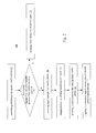
Fig. 4 is a flowchart of an operating method of a mobile device in accordance with one embodiment of the present disclosure. - Reference will now be made in detail to the present embodiments of the invention, examples of which are illustrated in the accompanying drawings. Wherever possible, the same reference numbers are used in the drawings and the description to refer to the same or like parts.
- It will be understood that, in the description herein and throughout the claims that follow, when an element is referred to as being "connected" or "coupled" to another element, it can be directly connected or coupled to the other element or intervening elements may be present. In contrast, when an element is referred to as being "directly connected" or "directly coupled" to another element, there are no intervening elements present. Moreover, "electrically connect" or "connect" can further refer to the interoperation or interaction between two or more elements.
- It will be understood that, in the description herein and throughout the claims that follow, although the terms "first," "second," etc. may be used to describe various elements, these elements should not be limited by these terms. These terms are only used to distinguish one element from another. For example, a first element could be termed a second element, and, similarly, a second element could be termed a first element, without departing from the scope of the embodiments.
- It will be understood that, in the description herein and throughout the claims that follow, the terms "comprise" or "comprising," "include" or "including," "have" or "having," "contain" or "containing" and the like used herein are to be understood to be open-ended, i.e., to mean including but not limited to.
- It will be understood that, in the description herein and throughout the claims that follow, the phrase "and/or" includes any and all combinations of one or more of the associated listed items.
- One aspect of the present disclosure is related to a mobile device. In the paragraphs below, a smart phone or a tablet computer will be taken as an example to describe details of the mobile device. However, the present disclosure is not limited in this regard.
-
Fig. 1 illustrates awireless power system 100 in accordance with one embodiment of the present disclosure. In this embodiment, thewireless power system 100 includes apower providing equipment 110 and a mobile device MD1. In this embodiment, thepower providing equipment 110 includes aprocessor 112, awireless power transmitter 114, and acommunication receiver 116. Theprocessor 112, thewireless power transmitter 114, and thecommunication receiver 116 are electrically connected. In this embodiment, the mobile device MD1 includes aprocessor 122, awireless power receiver 124, abattery 126, acommunication transmitter 127, and acharging module 128. Theprocessor 122, thewireless power receiver 124, thebattery 126, thecommunication transmitter 127, and thecharging module 128 are electrically connected. - In one embodiment, each of the
processors wireless power transmitter 114 and thewireless power receiver 124 may be realized by, for example, a coil, but is not limited in this regard. In one embodiment, each of thecommunication receiver 116 and thecommunication transmitter 127 may be realized by a suitable communication module, such as a wifi module or a bluebooth module, but is not limited in this regard. In one embodiment, thecharging module 128 may be realized by, for example, a circuit, but is not limited in this regard. - In one embodiment, the
processor 112 of thepower providing equipment 110 is configured to control thewireless power transmitter 114 to transmit a wireless power signal to the mobile device MD1 to charge thebattery 126 of the mobile device MD1. Theprocessors 122 of the mobile device MD1 is configured to determine whether to control thecommunication transmitter 127 to request thepower providing equipment 110 to stop charging thebattery 126 of the mobile device MD1 according to the power of thebattery 126 or charging statues. In one embodiment, the operations between thepower providing equipment 110 and the mobile device MD1 conform to the regulations defined in a document "Wireless Power Transfer" released by Wireless Power Consortium (WPC). - Details of the present disclosure are described in the paragraphs below with reference to an operating method of a power providing equipment in
Fig. 2 . However, the present disclosure is not limited to the embodiment below. - It should be noted that the operating method can be applied to a power providing equipment having a structure that is the same as or similar to the structure of the
power providing equipment 110 shown inFig. 1 . To simplify the description below, in the following paragraphs, the embodiment shown inFig. 1 will be used as an example to describe the operating method according to an embodiment of the present disclosure. However, the present disclosure is not limited to application to the embodiment shown inFig. 1 . - In addition, it should be noted that in the steps of the following operating method, no particular sequence is required unless otherwise specified. Moreover, the following steps also may be performed simultaneously or the execution times thereof may at least partially overlap.
- Furthermore, the steps of the following operating method may be added to, replaced, and/or eliminated as appropriate, in accordance with various embodiments of the present disclosure.
- Reference is made to
Fig. 2 . Theoperating method 200 includes the steps below. - In step T1, the
power providing equipment 110 is in a Selection phase. Theprocessor 112 detects whether a mobile device approaches. When the mobile device MD1 approaches thepower providing equipment 110, theprocessor 112 may control thewireless power transceiver 116 to transmit a wireless power signal to the mobile device MD1 to make the mobile device MD1 to response according to the wireless power signal. - In step T2, after the
processor 112 transmits the wireless power signal to the mobile device MD1, theprocessor 112 determines whether a first end power transfer message, which indicates a power of thebattery 126 of the mobile device MD1 is full, is received through thecommunication receiver 116. If so, step S3 is executed. If not, step S4 is executed. - In step T3, under a condition that the first end power transfer message is received, the
processor 112 controls thewireless power transceiver 116 to stop the wireless power signal and refrains charging thebattery 126 of the mobile device MD1. - In step T4, under a condition that the first end power transfer message is not received, the
processor 112 receives a signal strength packet from the mobile device MD1 through thecommunication receiver 116, which indicates the degree of coupling between thewireless power transmitter 114, and thewireless power receiver 124. - After the
power providing equipment 110 receives the signal strength packet from the mobile device MD1, thepower providing equipment 110 enters an Identification and Configuration phase. In such a phase, theprocessor 112 receives identification information of the mobile device MD1 from the mobile device MD1 through thecommunication receiver 116. - In one embodiment, the identification information includes a unique ID of the mobile device MD1 or the
wireless power receiver 124. In one embodiment, the unique ID is determined by the manufacturer of the mobile device MD1 or thewireless power receiver 124. In one embodiment, the unique ID includes a manufacture code and a (basic/extended) device identifier. In one embodiment, the unique ID corresponds to some modules in the mobile device MD1 other than thewireless power receiver 124. In one embodiment, the unique ID corresponds to an international mobile subscriber identity (IMSI) and/or a radio network temporary identifier (RNTI) of a cellular module (not shown). In one embodiment, the unique ID corresponds to a near field communication (NFC) ID of a NFC module (not shown) and/or a bluetooth low energy (BLE) ID of a BLE module (not shown). In one embodiment, the unique ID corresponds to these modules in the mobile device MD1 may be encoded (e.g., scrambled, truncated). - In step T5, after the identification information of the mobile device MD1 is received, the
power providing equipment 110 enters a Power Transfer phase. In this phase, theprocessor 112 controls thewireless power transmitter 114 to charge thebattery 126 of the mobile device MD1 by utilizing the wireless power signal. - In one embodiment, the
processor 112 may periodically receive a control error packet through thecommunication receiver 116 from the mobile device MD1 in the Power Transfer phase to ensure the communication between thepower providing equipment 110 and the mobile device MD1 is valid. When theprocessor 112 fails to receive the control error packet in a right timing, theprocessor 112 may control thewireless power transmitter 114 to stop transmitting the wireless power signal and terminate the charging of thebattery 126. - In step T6, when the
battery 126 is fully charged by utilizing the wireless power signal transmitted from thewireless power transmitter 114, theprocessor 112 receives a second end power transfer message through thecommunication receiver 116 from the mobile device MD1. - In step T7, after the
processor 112 receives the second end power transfer message, theprocessor 112 controls thewireless power transmitter 114 to stop the wireless power signal corresponding to the second end power transfer message. At this time, thepower providing equipment 110 returns to the Selection phase. - In one embodiment, each of the first end power transfer message, the signal strength packet, the identification information, the control error packet, and the second end power transfer message may be transmitted by an in-band communication attached to the wireless power signal. In one embodiment, these messages and packets may be transmitted by utilizing a load modulation technique, but the present disclosure is not limited to this embodiment. In another embodiment, these messages and packets may be transmitted by an out-band communication that is realized by another type of communication. In one embodiment, these messages and packets may be transmitted by utilizing bluetooth low energy (BLE), but the present disclosure is not limited to this embodiment. In one embodiment, the first end power transfer message, the signal strength packet, and the identification information are received at a beginning of the
wireless power transmitter 114 transmitting the wireless power signal to the mobile device MD1. - In one embodiment, the second end power transfer message and the first end power transfer message are different, so that the
processor 112 can determine whether the mobile device MD1 is replaced by another mobile device and provide an alarm. - More specifically, the
processor 112 can determine whether the mobile device MD1 is replaced by a mobile device MD2 according to whether the first end power transfer message is received after thebattery 126 of the mobile device MD1 is charged by utilizing the wireless power signal (i.e., in the Power Transfer phase). When theprocessor 112 receives a first end power transfer message (which is actually from the mobile device MD2) after thebattery 126 of the mobile device MD1 is charged by utilizing the wireless power signal, theprocessor 112 can determine that the mobile device MD1 is replaced since the first end power transfer message is inadequately presented. In other words, theprocessor 112 is able to determine whether the mobile device MD1 is replaced by the mobile device MD2 according to whether the first end power transfer message is received after receiving the identification information of the mobile device MD1 from the mobile device MD1. - Details of the formats of the second end power transfer message and the first end power transfer message are described in the paragraphs below with reference to
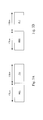
Figs. 3A-3C . - Particular reference is made to
Figs. 3A and 3B . In one embodiment, the second end power transfer message includes a header HD1 and a payload PL1. Both of the header HD1 and the payload PL1 have a length of one byte. The first end power transfer message includes a header HD2 and a payload PL2. Both of the header HD2 and the payload PL2 have a length of one byte. - In one embodiment, the headers HD1, HD2 of the second end power transfer message and the first end power transfer message are different. For instance, the header HD1 of the second end power transfer message may be "0x02", and the header HD2 of the first end power transfer message may be "0x99"
- In one embodiment, the payloads PL1, PL2 of the second end power transfer message and the first end power transfer message are different. For instance, the payload PL1 of the second end power transfer message may be "0x01", and the payload PL2 of the first end power transfer message may be "0x09"
- Particular reference is made to
Fig. 3C . In one embodiment, the formats of the second end power transfer message and the first end power transfer message are different, For example, in one embodiment, the order of the header HD1 and the payload PL1 of the second end power transfer message is different from the order of a header HD2 and the payload PL2 of the first end power transfer message. That is, the header HD1 is ahead of the payload PL1, and the payload PL2 is ahead of the header HD2. - Through such configurations, the
processor 112 is able to distinguish the second end power transfer message and the first end power transfer message. - In some approaches, the format of the second end power transfer message and the first end power transfer message are identical. In such a configuration, when the charged mobile device MD1 is replaced by the mobile device MD2 with full energy (i.e., the power of the
battery 136 of the mobile device MD2 is full), thewireless power system 100 may incorrectly determine that thebattery 126 of the mobile device MD1 is fully charged according to the first end power transfer message from the mobile device MD2, and fail to provide an alarm. - Compared with the approaches above, in one embodiment of the present disclosure, since the formats of the second end power transfer message and the first end power transfer message are different, the
processor 112 can acknowledge that the mobile device MD1 is replaced by another mobile device according to whether the first end power transfer message is received at an incorrect timing. - Details of the present disclosure are described in the paragraphs below with reference to an operating method of a mobile device in
Fig. 4 . However, the present disclosure is not limited to the embodiment below. - It should be noted that the operating method can be applied to a mobile device having a structure that is the same as or similar to the structure of the mobile device MD1 shown in
Fig. 1 . To simplify the description below, in the following paragraphs, the embodiment shown inFig. 1 will be used as an example to describe the operating method according to an embodiment of the present disclosure. However, the present disclosure is not limited to application to the embodiment shown inFig. 1 . - In addition, it should be noted that in the steps of the following operating method, no particular sequence is required unless otherwise specified. Moreover, the following steps also may be performed simultaneously or the execution times thereof may at least partially overlap.
- Furthermore, the steps of the following operating method may be added to, replaced, and/or eliminated as appropriate, in accordance with various embodiments of the present disclosure.
- Reference is made to
Fig. 4 . Theoperating method 300 includes the steps below. - In step S1, the mobile device MD1 is in a Selection phase. In such a phase, the
wireless power receiver 124 receives a wireless power signal from thepower providing equipment 110. - In step S2, the
processor 122 determines whether the power of thebattery 126 is full after receiving the wireless power signal. If so, step S3 is executed. If not, step S4 is executed. - In step S3, under a condition that the power of the
battery 126 is full, theprocessor 122 controls thecommunication transmitter 127 to transmit a first end power transfer message to thepower providing equipment 110, so that thepower providing equipment 110 stops providing the wireless power signal according to the first end power transfer message. - In step S4, under a condition that the power of the
battery 126 is not full theprocessor 122 controls thecommunication transmitter 127 to transmit a signal strength packet to thepower providing equipment 110 and enters an Identification and Configuration phase. In the Identification and Configuration phase, theprocessor 122 may control thecommunication transmitter 127 to transmit identification information of the mobile device MD1 to thepower providing equipment 110. - In step S5, after the
processor 122 controls thecommunication transmitter 127 to transmit the identification information of the mobile device MD1 to thepower providing equipment 110, the mobile device MD1 enters a Power Transfer phase. In such a phase, theprocessor 122 controls thecharging module 128 to charge thebattery 126 by utilizing the wireless power signal received from thepower providing equipment 110. - In one embodiment, the
processor 122 may controls thecommunication transmitter 127 to periodically transmit a control error packet to thepower providing equipment 110 in the Power Transfer phase to ensure the communication between thepower providing equipment 110 and the mobile device MD1 is valid. - In step S6, when charging of the
battery 126 is fully charged by thecharging module 128, theprocessor 122 controls thecommunication transmitter 127 to transmit a second end power transfer message with a format different from the first end power transfer message to thepower providing equipment 110, so that thepower providing equipment 110 stops providing the wireless power signal according to the second end power transfer message. At this time, the mobile device MD1 returns to Selection phase. - In one embodiment, the first end power transfer message, the signal strength packet, and the identification information are transmitted at a beginning of the
wireless power receiver 124 receiving the wireless power signal from thepower providing equipment 110. - By utilizing the second end power transfer message and the first end power transfer message with different format, the
power providing equipment 110 can determine whether the mobile device MD1 is replaced by another mobile device and provide an alarm. - It should be noted that details of the first end power transfer message, the signal strength packet, the identification information, the control error packet, and the second end power transfer message can be ascertained with reference to the paragraphs above, and a description in this regard will not be repeated herein.
- Although the present invention has been described in considerable detail with reference to certain embodiments thereof, other embodiments are possible. Therefore, the scope of the appended claims should not be limited to the description of the embodiments contained herein.
Claims (15)
- A mobile device comprises:a battery;a wireless power receiver configured for receiving a wireless power signal from a power providing equipment;a communication transmitter;a charging module; anda processor electrically connected with the battery, the wireless power receiver, the communication transmitter, and the charging module, wherein the processor is configured for:controlling the communication transmitter to transmit a first end power transfer message to the power providing equipment under a condition that the power of the battery is full at a beginning of the wireless power receiver receiving the wireless power signal from the power providing equipment, so that the power providing equipment stops providing the wireless power signal according to the first end power transfer message;controlling the charging module to charge the battery by utilizing the wireless power signal received from the power providing equipment under a condition that the power of the battery is not full; andcontrolling the communication transmitter to transmit a second end power transfer message to the power providing equipment under a condition that the battery is fully charged by the charging module, so that the power providing equipment stops providing the wireless power signal according to the second end power transfer message;wherein the first end power transfer message and the second end power transfer message are different.
- The mobile device as claimed in claim 1, wherein formats of the first end power transfer message and the second end power transfer message are different.
- The mobile device as claimed in claim 1, wherein payloads of the first end power transfer message and the second end power transfer message are different.
- The mobile device as claimed in claim 1, wherein headers of the first end power transfer message and the second end power transfer message are different.
- The mobile device as claimed in claim 1, wherein an order of a header and a payload of first end power transfer message is different from an order of a header and a payload of the second end power transfer message.
- The mobile device as claimed in claim 1, wherein the processor is further configured for:controlling the communication transmitter to transmit identification information of the mobile device to the power providing equipment under a condition that the battery is not full at the beginning of the wireless power receiver receiving the wireless power signal from the power providing equipment.
- The mobile device as claimed in claim 5, wherein the processor is further configured for:controlling the communication transmitter to transmit a control error packet to the power providing equipment periodically after transmitting the identification information of the mobile device.
- A power providing equipment comprises:a wireless power transmitter configured for transmitting a wireless power signal to a mobile device;a communication receiver; anda processor electrically connected with the wireless power transmitter and the communication receiver, wherein the processor is configured for:determining whether a first end power transfer message from the mobile device is received, wherein the first end power transfer message indicates a power of a battery of the mobile device is full at a beginning of the wireless power transmitter transmitting the wireless power signal to the mobile device;controlling the wireless power transmitter to stop transmitting the wireless power signal to the mobile device under a condition that the first end power transfer message is received;receiving, through the communication receiver, a second end power transfer message from the mobile device under a condition that the battery is fully charged by utilizing the wireless power signal transmitted from the wireless power transmitter; andcontrolling the wireless power transmitter to stop the power signal corresponding to the second end power transfer message;wherein the first end power transfer message and the second end power transfer message are different.
- The power providing equipment as claimed in claim 8, wherein formats of the first end power transfer message and the second end power transfer message are different.
- The power providing equipment as claimed in claim 8, wherein payloads of the second end power transfer message and the first end power transfer message are different.
- The power providing equipment as claimed in claim 8, wherein headers of the second end power transfer message and the first end power transfer message are different.
- The mobile device as claimed in claim 8, wherein an order of a header and a payload of the second end power transfer message is different from an order of a header and a payload of the first end power transfer message.
- The power providing equipment as claimed in claim 8, wherein the processor is further configured for:receiving identification information of the mobile device from the mobile device under a condition that the power of the battery is not full at the beginning of the wireless power transmitter transmitting the wireless power signal to the mobile device.
- The power providing equipment as claimed in claim 13, wherein the processor is further configured for:determining whether the mobile device is replaced by another mobile device according to whether the first end power transfer message is received after receiving the identification information of the mobile device from the mobile device.
- The power providing equipment as claimed in claim 8, wherein the processor is further configured for:receiving another first end power transfer message from another mobile device after charging the battery of the mobile device; anddetermining the mobile device is replaced by the another mobile device according to the another first end power transfer message.
Applications Claiming Priority (1)
| Application Number | Priority Date | Filing Date | Title |
|---|---|---|---|
| US201461985481P | 2014-04-29 | 2014-04-29 |
Publications (2)
| Publication Number | Publication Date |
|---|---|
| EP2940828A1 true EP2940828A1 (en) | 2015-11-04 |
| EP2940828B1 EP2940828B1 (en) | 2017-06-28 |
Family
ID=53396146
Family Applications (1)
| Application Number | Title | Priority Date | Filing Date |
|---|---|---|---|
| EP15165710.3A Active EP2940828B1 (en) | 2014-04-29 | 2015-04-29 | A mobile device and power providing equipment for wireless charging |
Country Status (2)
| Country | Link |
|---|---|
| US (1) | US9973025B2 (en) |
| EP (1) | EP2940828B1 (en) |
Cited By (1)
| Publication number | Priority date | Publication date | Assignee | Title |
|---|---|---|---|---|
| CN108233545A (en) * | 2018-01-26 | 2018-06-29 | 维沃移动通信有限公司 | A kind of wireless charging receiving circuit, electronic equipment and wireless charging method |
Families Citing this family (1)
| Publication number | Priority date | Publication date | Assignee | Title |
|---|---|---|---|---|
| WO2015115723A1 (en) * | 2014-01-29 | 2015-08-06 | 에스케이플래닛 주식회사 | Wireless charging device and terminal, wireless charging system including same, method for controlling same, and recording medium having computer program recorded thereon |
Citations (4)
| Publication number | Priority date | Publication date | Assignee | Title |
|---|---|---|---|---|
| US20080174267A1 (en) * | 2007-01-17 | 2008-07-24 | Seiko Epson Corporation | Power transmission control device, power reception control device, non-contact power transmission system, power transmission device, power reception device and electronic instrument |
| EP2086085A1 (en) * | 2006-11-08 | 2009-08-05 | Panasonic Corporation | Non-contact charger, electronic device, battery pack, and non-contact charge system |
| US20130200844A1 (en) * | 2012-02-06 | 2013-08-08 | Samsung Electronics Co., Ltd. | Wireless power charging method and apparatus |
| EP2696468A1 (en) * | 2011-04-01 | 2014-02-12 | NEC CASIO Mobile Communications, Ltd. | Power transmitting device, power receiving device, power transmitting method of power transmitting device, and power receiving method of power receiving device |
Family Cites Families (3)
| Publication number | Priority date | Publication date | Assignee | Title |
|---|---|---|---|---|
| JP5804694B2 (en) * | 2010-11-29 | 2015-11-04 | キヤノン株式会社 | Electronic apparatus and method |
| KR101781650B1 (en) * | 2011-10-04 | 2017-09-26 | 삼성전자주식회사 | Wireless power multi-charge method and power transmitter |
| JP6164857B2 (en) * | 2013-02-12 | 2017-07-19 | キヤノン株式会社 | Power feeding device, power feeding device control method, power receiving device, power receiving device control method, program |
-
2015
- 2015-04-28 US US14/698,827 patent/US9973025B2/en active Active
- 2015-04-29 EP EP15165710.3A patent/EP2940828B1/en active Active
Patent Citations (4)
| Publication number | Priority date | Publication date | Assignee | Title |
|---|---|---|---|---|
| EP2086085A1 (en) * | 2006-11-08 | 2009-08-05 | Panasonic Corporation | Non-contact charger, electronic device, battery pack, and non-contact charge system |
| US20080174267A1 (en) * | 2007-01-17 | 2008-07-24 | Seiko Epson Corporation | Power transmission control device, power reception control device, non-contact power transmission system, power transmission device, power reception device and electronic instrument |
| EP2696468A1 (en) * | 2011-04-01 | 2014-02-12 | NEC CASIO Mobile Communications, Ltd. | Power transmitting device, power receiving device, power transmitting method of power transmitting device, and power receiving method of power receiving device |
| US20130200844A1 (en) * | 2012-02-06 | 2013-08-08 | Samsung Electronics Co., Ltd. | Wireless power charging method and apparatus |
Cited By (2)
| Publication number | Priority date | Publication date | Assignee | Title |
|---|---|---|---|---|
| CN108233545A (en) * | 2018-01-26 | 2018-06-29 | 维沃移动通信有限公司 | A kind of wireless charging receiving circuit, electronic equipment and wireless charging method |
| CN108233545B (en) * | 2018-01-26 | 2020-03-31 | 维沃移动通信有限公司 | Wireless charging receiving circuit, electronic equipment and wireless charging method |
Also Published As
| Publication number | Publication date |
|---|---|
| EP2940828B1 (en) | 2017-06-28 |
| US9973025B2 (en) | 2018-05-15 |
| US20150311743A1 (en) | 2015-10-29 |
Similar Documents
| Publication | Publication Date | Title |
|---|---|---|
| US10868359B2 (en) | Hybrid on board unit and roadside unit supporting wave-V2X and C-V2X | |
| KR101829772B1 (en) | System and method for safe wireless charging station | |
| EP3624303B1 (en) | A system and a method for charging multiple power receivers in a wireless charging environment | |
| US8929306B2 (en) | NAS-based signaling protocol for overload protection of random access in massive machine type communication | |
| EP3002974B1 (en) | Communication system and communication method, communication apparatus and control method for the same, program, and storage medium | |
| US20150244201A1 (en) | Method of Handling Wireless Charging Authentication | |
| EP2822142A2 (en) | Method for wireless charging authentication and related wireless charging system | |
| US10779342B2 (en) | Load balance for dual interface automotive wi-fi controllers for P2P devices | |
| US9548795B2 (en) | Method of identifying wireless power receiver in wireless power system | |
| US10312746B2 (en) | Power providing equipment, mobile device, operating method of mobile device | |
| US10445952B2 (en) | Motor vehicle having a communication unit for multiple control units | |
| EP3327894A1 (en) | Wireless charging device for vehicle | |
| US10763705B2 (en) | Method of pairing receiver with wireless charger transmitter | |
| US20140298447A1 (en) | Method for Enhancing Security of Portable Electronic Device and Related Wireless Charging System | |
| US11175904B2 (en) | Method for controlling a charging station for charging vehicles and a charging station and a vehicle therefor | |
| WO2015051050A1 (en) | Wireless charger system having adaptive load modulation | |
| EP2685747B1 (en) | Method of operating a module for wireless communication or the like wireless communication terminal, module for wireless communication and device of an integrated circuit card and a system of a communication equipment for operating the module | |
| US9450424B2 (en) | Power providing equipment, mobile device, operating method of mobile device | |
| KR102085175B1 (en) | Method, apparatus, and system for adjusting data packet length in near field communication (NCF) | |
| US9628149B2 (en) | Emulation of multiple NFC devices inside a communication device | |
| US20160036498A1 (en) | Method of Wireless Power Connection | |
| US9842499B2 (en) | Device enabling exchange of abnormal signal among vehicles via Wi-Fi direct network, and control method therefor | |
| US9973025B2 (en) | Power providing equipment, mobile device, operating method of mobile device | |
| US9807225B2 (en) | Method for providing a function in a computer system of a vehicle | |
| US9635709B2 (en) | Electronic device |
Legal Events
| Date | Code | Title | Description |
|---|---|---|---|
| PUAI | Public reference made under article 153(3) epc to a published international application that has entered the european phase |
Free format text: ORIGINAL CODE: 0009012 |
|
| 17P | Request for examination filed |
Effective date: 20150429 |
|
| AK | Designated contracting states |
Kind code of ref document: A1 Designated state(s): AL AT BE BG CH CY CZ DE DK EE ES FI FR GB GR HR HU IE IS IT LI LT LU LV MC MK MT NL NO PL PT RO RS SE SI SK SM TR |
|
| AX | Request for extension of the european patent |
Extension state: BA ME |
|
| RBV | Designated contracting states (corrected) |
Designated state(s): AL AT BE BG CH CY CZ DE DK EE ES FI FR GB GR HR HU IE IS IT LI LT LU LV MC MK MT NL NO PL PT RO RS SE SI SK SM TR |
|
| REG | Reference to a national code |
Ref country code: DE Ref legal event code: R079 Ref document number: 602015003284 Country of ref document: DE Free format text: PREVIOUS MAIN CLASS: H02J0007020000 Ipc: H02J0050100000 |
|
| GRAP | Despatch of communication of intention to grant a patent |
Free format text: ORIGINAL CODE: EPIDOSNIGR1 |
|
| RIC1 | Information provided on ipc code assigned before grant |
Ipc: H02J 50/10 20160101AFI20170111BHEP Ipc: H02J 50/80 20160101ALI20170111BHEP |
|
| INTG | Intention to grant announced |
Effective date: 20170127 |
|
| GRAS | Grant fee paid |
Free format text: ORIGINAL CODE: EPIDOSNIGR3 |
|
| GRAA | (expected) grant |
Free format text: ORIGINAL CODE: 0009210 |
|
| AK | Designated contracting states |
Kind code of ref document: B1 Designated state(s): AL AT BE BG CH CY CZ DE DK EE ES FI FR GB GR HR HU IE IS IT LI LT LU LV MC MK MT NL NO PL PT RO RS SE SI SK SM TR |
|
| REG | Reference to a national code |
Ref country code: GB Ref legal event code: FG4D |
|
| REG | Reference to a national code |
Ref country code: CH Ref legal event code: EP |
|
| REG | Reference to a national code |
Ref country code: AT Ref legal event code: REF Ref document number: 905635 Country of ref document: AT Kind code of ref document: T Effective date: 20170715 |
|
| REG | Reference to a national code |
Ref country code: IE Ref legal event code: FG4D |
|
| REG | Reference to a national code |
Ref country code: DE Ref legal event code: R096 Ref document number: 602015003284 Country of ref document: DE |
|
| REG | Reference to a national code |
Ref country code: NL Ref legal event code: FP |
|
| PG25 | Lapsed in a contracting state [announced via postgrant information from national office to epo] |
Ref country code: LT Free format text: LAPSE BECAUSE OF FAILURE TO SUBMIT A TRANSLATION OF THE DESCRIPTION OR TO PAY THE FEE WITHIN THE PRESCRIBED TIME-LIMIT Effective date: 20170628 Ref country code: FI Free format text: LAPSE BECAUSE OF FAILURE TO SUBMIT A TRANSLATION OF THE DESCRIPTION OR TO PAY THE FEE WITHIN THE PRESCRIBED TIME-LIMIT Effective date: 20170628 Ref country code: NO Free format text: LAPSE BECAUSE OF FAILURE TO SUBMIT A TRANSLATION OF THE DESCRIPTION OR TO PAY THE FEE WITHIN THE PRESCRIBED TIME-LIMIT Effective date: 20170928 Ref country code: HR Free format text: LAPSE BECAUSE OF FAILURE TO SUBMIT A TRANSLATION OF THE DESCRIPTION OR TO PAY THE FEE WITHIN THE PRESCRIBED TIME-LIMIT Effective date: 20170628 Ref country code: GR Free format text: LAPSE BECAUSE OF FAILURE TO SUBMIT A TRANSLATION OF THE DESCRIPTION OR TO PAY THE FEE WITHIN THE PRESCRIBED TIME-LIMIT Effective date: 20170929 |
|
| REG | Reference to a national code |
Ref country code: LT Ref legal event code: MG4D |
|
| REG | Reference to a national code |
Ref country code: AT Ref legal event code: MK05 Ref document number: 905635 Country of ref document: AT Kind code of ref document: T Effective date: 20170628 |
|
| PG25 | Lapsed in a contracting state [announced via postgrant information from national office to epo] |
Ref country code: RS Free format text: LAPSE BECAUSE OF FAILURE TO SUBMIT A TRANSLATION OF THE DESCRIPTION OR TO PAY THE FEE WITHIN THE PRESCRIBED TIME-LIMIT Effective date: 20170628 Ref country code: LV Free format text: LAPSE BECAUSE OF FAILURE TO SUBMIT A TRANSLATION OF THE DESCRIPTION OR TO PAY THE FEE WITHIN THE PRESCRIBED TIME-LIMIT Effective date: 20170628 Ref country code: BG Free format text: LAPSE BECAUSE OF FAILURE TO SUBMIT A TRANSLATION OF THE DESCRIPTION OR TO PAY THE FEE WITHIN THE PRESCRIBED TIME-LIMIT Effective date: 20170928 Ref country code: SE Free format text: LAPSE BECAUSE OF FAILURE TO SUBMIT A TRANSLATION OF THE DESCRIPTION OR TO PAY THE FEE WITHIN THE PRESCRIBED TIME-LIMIT Effective date: 20170628 |
|
| PG25 | Lapsed in a contracting state [announced via postgrant information from national office to epo] |
Ref country code: RO Free format text: LAPSE BECAUSE OF FAILURE TO SUBMIT A TRANSLATION OF THE DESCRIPTION OR TO PAY THE FEE WITHIN THE PRESCRIBED TIME-LIMIT Effective date: 20170628 Ref country code: CZ Free format text: LAPSE BECAUSE OF FAILURE TO SUBMIT A TRANSLATION OF THE DESCRIPTION OR TO PAY THE FEE WITHIN THE PRESCRIBED TIME-LIMIT Effective date: 20170628 Ref country code: EE Free format text: LAPSE BECAUSE OF FAILURE TO SUBMIT A TRANSLATION OF THE DESCRIPTION OR TO PAY THE FEE WITHIN THE PRESCRIBED TIME-LIMIT Effective date: 20170628 Ref country code: AT Free format text: LAPSE BECAUSE OF FAILURE TO SUBMIT A TRANSLATION OF THE DESCRIPTION OR TO PAY THE FEE WITHIN THE PRESCRIBED TIME-LIMIT Effective date: 20170628 Ref country code: SK Free format text: LAPSE BECAUSE OF FAILURE TO SUBMIT A TRANSLATION OF THE DESCRIPTION OR TO PAY THE FEE WITHIN THE PRESCRIBED TIME-LIMIT Effective date: 20170628 |
|
| PG25 | Lapsed in a contracting state [announced via postgrant information from national office to epo] |
Ref country code: PL Free format text: LAPSE BECAUSE OF FAILURE TO SUBMIT A TRANSLATION OF THE DESCRIPTION OR TO PAY THE FEE WITHIN THE PRESCRIBED TIME-LIMIT Effective date: 20170628 Ref country code: IS Free format text: LAPSE BECAUSE OF FAILURE TO SUBMIT A TRANSLATION OF THE DESCRIPTION OR TO PAY THE FEE WITHIN THE PRESCRIBED TIME-LIMIT Effective date: 20171028 Ref country code: ES Free format text: LAPSE BECAUSE OF FAILURE TO SUBMIT A TRANSLATION OF THE DESCRIPTION OR TO PAY THE FEE WITHIN THE PRESCRIBED TIME-LIMIT Effective date: 20170628 Ref country code: SM Free format text: LAPSE BECAUSE OF FAILURE TO SUBMIT A TRANSLATION OF THE DESCRIPTION OR TO PAY THE FEE WITHIN THE PRESCRIBED TIME-LIMIT Effective date: 20170628 Ref country code: IT Free format text: LAPSE BECAUSE OF FAILURE TO SUBMIT A TRANSLATION OF THE DESCRIPTION OR TO PAY THE FEE WITHIN THE PRESCRIBED TIME-LIMIT Effective date: 20170628 |
|
| REG | Reference to a national code |
Ref country code: FR Ref legal event code: PLFP Year of fee payment: 4 |
|
| REG | Reference to a national code |
Ref country code: DE Ref legal event code: R097 Ref document number: 602015003284 Country of ref document: DE |
|
| PG25 | Lapsed in a contracting state [announced via postgrant information from national office to epo] |
Ref country code: DK Free format text: LAPSE BECAUSE OF FAILURE TO SUBMIT A TRANSLATION OF THE DESCRIPTION OR TO PAY THE FEE WITHIN THE PRESCRIBED TIME-LIMIT Effective date: 20170628 |
|
| PLBE | No opposition filed within time limit |
Free format text: ORIGINAL CODE: 0009261 |
|
| STAA | Information on the status of an ep patent application or granted ep patent |
Free format text: STATUS: NO OPPOSITION FILED WITHIN TIME LIMIT |
|
| 26N | No opposition filed |
Effective date: 20180329 |
|
| PG25 | Lapsed in a contracting state [announced via postgrant information from national office to epo] |
Ref country code: SI Free format text: LAPSE BECAUSE OF FAILURE TO SUBMIT A TRANSLATION OF THE DESCRIPTION OR TO PAY THE FEE WITHIN THE PRESCRIBED TIME-LIMIT Effective date: 20170628 |
|
| PG25 | Lapsed in a contracting state [announced via postgrant information from national office to epo] |
Ref country code: MC Free format text: LAPSE BECAUSE OF FAILURE TO SUBMIT A TRANSLATION OF THE DESCRIPTION OR TO PAY THE FEE WITHIN THE PRESCRIBED TIME-LIMIT Effective date: 20170628 |
|
| REG | Reference to a national code |
Ref country code: CH Ref legal event code: PL |
|
| REG | Reference to a national code |
Ref country code: BE Ref legal event code: MM Effective date: 20180430 |
|
| REG | Reference to a national code |
Ref country code: IE Ref legal event code: MM4A |
|
| PG25 | Lapsed in a contracting state [announced via postgrant information from national office to epo] |
Ref country code: LU Free format text: LAPSE BECAUSE OF NON-PAYMENT OF DUE FEES Effective date: 20180429 |
|
| PG25 | Lapsed in a contracting state [announced via postgrant information from national office to epo] |
Ref country code: CH Free format text: LAPSE BECAUSE OF NON-PAYMENT OF DUE FEES Effective date: 20180430 Ref country code: BE Free format text: LAPSE BECAUSE OF NON-PAYMENT OF DUE FEES Effective date: 20180430 Ref country code: LI Free format text: LAPSE BECAUSE OF NON-PAYMENT OF DUE FEES Effective date: 20180430 |
|
| PG25 | Lapsed in a contracting state [announced via postgrant information from national office to epo] |
Ref country code: IE Free format text: LAPSE BECAUSE OF NON-PAYMENT OF DUE FEES Effective date: 20180429 |
|
| PG25 | Lapsed in a contracting state [announced via postgrant information from national office to epo] |
Ref country code: MT Free format text: LAPSE BECAUSE OF NON-PAYMENT OF DUE FEES Effective date: 20180429 |
|
| PG25 | Lapsed in a contracting state [announced via postgrant information from national office to epo] |
Ref country code: TR Free format text: LAPSE BECAUSE OF FAILURE TO SUBMIT A TRANSLATION OF THE DESCRIPTION OR TO PAY THE FEE WITHIN THE PRESCRIBED TIME-LIMIT Effective date: 20170628 |
|
| PG25 | Lapsed in a contracting state [announced via postgrant information from national office to epo] |
Ref country code: PT Free format text: LAPSE BECAUSE OF FAILURE TO SUBMIT A TRANSLATION OF THE DESCRIPTION OR TO PAY THE FEE WITHIN THE PRESCRIBED TIME-LIMIT Effective date: 20170628 |
|
| PG25 | Lapsed in a contracting state [announced via postgrant information from national office to epo] |
Ref country code: MK Free format text: LAPSE BECAUSE OF NON-PAYMENT OF DUE FEES Effective date: 20170628 Ref country code: HU Free format text: LAPSE BECAUSE OF FAILURE TO SUBMIT A TRANSLATION OF THE DESCRIPTION OR TO PAY THE FEE WITHIN THE PRESCRIBED TIME-LIMIT; INVALID AB INITIO Effective date: 20150429 Ref country code: CY Free format text: LAPSE BECAUSE OF FAILURE TO SUBMIT A TRANSLATION OF THE DESCRIPTION OR TO PAY THE FEE WITHIN THE PRESCRIBED TIME-LIMIT Effective date: 20170628 |
|
| PG25 | Lapsed in a contracting state [announced via postgrant information from national office to epo] |
Ref country code: AL Free format text: LAPSE BECAUSE OF FAILURE TO SUBMIT A TRANSLATION OF THE DESCRIPTION OR TO PAY THE FEE WITHIN THE PRESCRIBED TIME-LIMIT Effective date: 20170628 |
|
| P01 | Opt-out of the competence of the unified patent court (upc) registered |
Effective date: 20230602 |
|
| PGFP | Annual fee paid to national office [announced via postgrant information from national office to epo] |
Ref country code: NL Payment date: 20250317 Year of fee payment: 11 |
|
| PGFP | Annual fee paid to national office [announced via postgrant information from national office to epo] |
Ref country code: FR Payment date: 20250310 Year of fee payment: 11 |
|
| PGFP | Annual fee paid to national office [announced via postgrant information from national office to epo] |
Ref country code: GB Payment date: 20250306 Year of fee payment: 11 |
|
| PGFP | Annual fee paid to national office [announced via postgrant information from national office to epo] |
Ref country code: DE Payment date: 20250305 Year of fee payment: 11 |