EP2940808B1 - Time-multiplexed driving of multi-colour lasers for quasi-simultaneous spectroscopic analysis - Google Patents
Time-multiplexed driving of multi-colour lasers for quasi-simultaneous spectroscopic analysis Download PDFInfo
- Publication number
- EP2940808B1 EP2940808B1 EP14166907.7A EP14166907A EP2940808B1 EP 2940808 B1 EP2940808 B1 EP 2940808B1 EP 14166907 A EP14166907 A EP 14166907A EP 2940808 B1 EP2940808 B1 EP 2940808B1
- Authority
- EP
- European Patent Office
- Prior art keywords
- laser
- sections
- time
- mir
- color
- Prior art date
- Legal status (The legal status is an assumption and is not a legal conclusion. Google has not performed a legal analysis and makes no representation as to the accuracy of the status listed.)
- Active
Links
- 238000004611 spectroscopical analysis Methods 0.000 title description 3
- 238000000034 method Methods 0.000 claims description 15
- 238000001228 spectrum Methods 0.000 claims description 13
- 238000001514 detection method Methods 0.000 claims description 8
- 238000001307 laser spectroscopy Methods 0.000 claims description 6
- 238000005259 measurement Methods 0.000 claims description 4
- 230000005855 radiation Effects 0.000 claims description 3
- 230000006641 stabilisation Effects 0.000 claims description 3
- 238000011105 stabilization Methods 0.000 claims description 3
- 239000007789 gas Substances 0.000 description 9
- 241000894007 species Species 0.000 description 7
- 238000010586 diagram Methods 0.000 description 5
- 230000017525 heat dissipation Effects 0.000 description 4
- 238000000862 absorption spectrum Methods 0.000 description 3
- 230000003287 optical effect Effects 0.000 description 3
- 238000004458 analytical method Methods 0.000 description 2
- 230000001419 dependent effect Effects 0.000 description 2
- 238000013461 design Methods 0.000 description 2
- 239000003814 drug Substances 0.000 description 2
- 229940079593 drug Drugs 0.000 description 2
- 230000000694 effects Effects 0.000 description 2
- 239000002360 explosive Substances 0.000 description 2
- 238000004519 manufacturing process Methods 0.000 description 2
- 239000000463 material Substances 0.000 description 2
- 238000012544 monitoring process Methods 0.000 description 2
- GPXJNWSHGFTCBW-UHFFFAOYSA-N Indium phosphide Chemical compound [In]#P GPXJNWSHGFTCBW-UHFFFAOYSA-N 0.000 description 1
- 238000010521 absorption reaction Methods 0.000 description 1
- 239000011149 active material Substances 0.000 description 1
- 230000007717 exclusion Effects 0.000 description 1
- 230000001747 exhibiting effect Effects 0.000 description 1
- 238000002474 experimental method Methods 0.000 description 1
- 230000003993 interaction Effects 0.000 description 1
- 238000004377 microelectronic Methods 0.000 description 1
- 230000035484 reaction time Effects 0.000 description 1
- 238000000926 separation method Methods 0.000 description 1
- 238000007493 shaping process Methods 0.000 description 1
- 230000000087 stabilizing effect Effects 0.000 description 1
- 230000001360 synchronised effect Effects 0.000 description 1
- 230000001960 triggered effect Effects 0.000 description 1
Images


Classifications
-
- H—ELECTRICITY
- H01—ELECTRIC ELEMENTS
- H01S—DEVICES USING THE PROCESS OF LIGHT AMPLIFICATION BY STIMULATED EMISSION OF RADIATION [LASER] TO AMPLIFY OR GENERATE LIGHT; DEVICES USING STIMULATED EMISSION OF ELECTROMAGNETIC RADIATION IN WAVE RANGES OTHER THAN OPTICAL
- H01S5/00—Semiconductor lasers
- H01S5/10—Construction or shape of the optical resonator, e.g. extended or external cavity, coupled cavities, bent-guide, varying width, thickness or composition of the active region
- H01S5/12—Construction or shape of the optical resonator, e.g. extended or external cavity, coupled cavities, bent-guide, varying width, thickness or composition of the active region the resonator having a periodic structure, e.g. in distributed feedback [DFB] lasers
-
- H—ELECTRICITY
- H01—ELECTRIC ELEMENTS
- H01S—DEVICES USING THE PROCESS OF LIGHT AMPLIFICATION BY STIMULATED EMISSION OF RADIATION [LASER] TO AMPLIFY OR GENERATE LIGHT; DEVICES USING STIMULATED EMISSION OF ELECTROMAGNETIC RADIATION IN WAVE RANGES OTHER THAN OPTICAL
- H01S5/00—Semiconductor lasers
- H01S5/40—Arrangement of two or more semiconductor lasers, not provided for in groups H01S5/02 - H01S5/30
- H01S5/4025—Array arrangements, e.g. constituted by discrete laser diodes or laser bar
- H01S5/4087—Array arrangements, e.g. constituted by discrete laser diodes or laser bar emitting more than one wavelength
-
- G—PHYSICS
- G01—MEASURING; TESTING
- G01J—MEASUREMENT OF INTENSITY, VELOCITY, SPECTRAL CONTENT, POLARISATION, PHASE OR PULSE CHARACTERISTICS OF INFRARED, VISIBLE OR ULTRAVIOLET LIGHT; COLORIMETRY; RADIATION PYROMETRY
- G01J3/00—Spectrometry; Spectrophotometry; Monochromators; Measuring colours
- G01J3/02—Details
- G01J3/10—Arrangements of light sources specially adapted for spectrometry or colorimetry
- G01J3/108—Arrangements of light sources specially adapted for spectrometry or colorimetry for measurement in the infrared range
-
- H—ELECTRICITY
- H01—ELECTRIC ELEMENTS
- H01S—DEVICES USING THE PROCESS OF LIGHT AMPLIFICATION BY STIMULATED EMISSION OF RADIATION [LASER] TO AMPLIFY OR GENERATE LIGHT; DEVICES USING STIMULATED EMISSION OF ELECTROMAGNETIC RADIATION IN WAVE RANGES OTHER THAN OPTICAL
- H01S5/00—Semiconductor lasers
- H01S5/06—Arrangements for controlling the laser output parameters, e.g. by operating on the active medium
- H01S5/062—Arrangements for controlling the laser output parameters, e.g. by operating on the active medium by varying the potential of the electrodes
- H01S5/06209—Arrangements for controlling the laser output parameters, e.g. by operating on the active medium by varying the potential of the electrodes in single-section lasers
- H01S5/06216—Pulse modulation or generation
-
- G—PHYSICS
- G01—MEASURING; TESTING
- G01N—INVESTIGATING OR ANALYSING MATERIALS BY DETERMINING THEIR CHEMICAL OR PHYSICAL PROPERTIES
- G01N21/00—Investigating or analysing materials by the use of optical means, i.e. using sub-millimetre waves, infrared, visible or ultraviolet light
- G01N21/17—Systems in which incident light is modified in accordance with the properties of the material investigated
- G01N21/25—Colour; Spectral properties, i.e. comparison of effect of material on the light at two or more different wavelengths or wavelength bands
- G01N21/31—Investigating relative effect of material at wavelengths characteristic of specific elements or molecules, e.g. atomic absorption spectrometry
- G01N21/35—Investigating relative effect of material at wavelengths characteristic of specific elements or molecules, e.g. atomic absorption spectrometry using infrared light
- G01N21/3504—Investigating relative effect of material at wavelengths characteristic of specific elements or molecules, e.g. atomic absorption spectrometry using infrared light for analysing gases, e.g. multi-gas analysis
-
- H—ELECTRICITY
- H01—ELECTRIC ELEMENTS
- H01S—DEVICES USING THE PROCESS OF LIGHT AMPLIFICATION BY STIMULATED EMISSION OF RADIATION [LASER] TO AMPLIFY OR GENERATE LIGHT; DEVICES USING STIMULATED EMISSION OF ELECTROMAGNETIC RADIATION IN WAVE RANGES OTHER THAN OPTICAL
- H01S5/00—Semiconductor lasers
- H01S5/04—Processes or apparatus for excitation, e.g. pumping, e.g. by electron beams
- H01S5/042—Electrical excitation ; Circuits therefor
- H01S5/0428—Electrical excitation ; Circuits therefor for applying pulses to the laser
Definitions
- the invention is related to time-multiplexed driving of multi-colour lasers for quasi-simultaneous spectroscopic analysis including a respective system and a method.
- MIR mid-infrared
- multi-color MIR lasers such as Quantum Cascade Laser (QCL) or Interband Cascade Laser (ICL) based on a heterogeneous active region and concatenated distributed feedback (DFB) gratings of different periodicities on a single waveguide ridge were proposed.
- QCL Quantum Cascade Laser
- ICL Interband Cascade Laser
- DFB distributed feedback
- the invention has the object to provide a system including a driver for a multi-color laser enabling quasi-simultaneous detection of multiple gas species using MIR laser spectroscopy which assembly is applicable for numerous applications ranging from air quality monitoring, medical breath analysis, drug and explosive detection to industrial process control.
- a method should be provided for quasi-simultaneous detection of multiple gas species.
- the instant invention comprises a MIR multi-color laser such as a Quantum Cascade Laser (QCL) or Interband Cascade Laser (ICL) with concatenated and electrically separated laser sections driven for quasi-simultaneous detection of multiple gas species.
- Driving of the respective laser sections is time-division multiplexed, such that at a given time only one wavelength is emitted.
- a single laser driver combined with an electronic switch is used to multiplex the laser sections.
- the system and the method use an optimal switching rate, which needs to be determined for a given system.
- Time division multiplexed driving essentially means, that the two or more laser sections of a multi-color laser are sequentially operated in time, i.e. at a given time, only one laser section is active, which allows detecting the gas species exhibiting absorption within the turning range of the given laser.
- the first laser section is switched off and a different laser section is used to detect other gas species.
- the object of the invention is solved by a system according to claim 1 and a method according to claim 5.
- an electronic switch is used which can distribute the driving current among the individual laser sections such that only one section is driven above the laser threshold and emits light, while all other sections are operated just below the threshold. Simultaneous driving of the non-active lasers below threshold minimizes the propagation loss of the lasing wavelength that gets otherwise reabsorbed in the unbiased active material.
- Such lasers must be driven with very short pulses of typically 5-10 ns and are tuned using a subthreshold current ramp to scan the laser wavelength; the time to measure an absorption spectrum using a pulsed DFB laser (or one section of a pulsed multi-color laser) is typically 100 ⁇ s.
- the pulsed lasers exhibit low heat dissipation due to low duty cycle operation, but require radio-frequency compatible switches with rather long dead-times. There are several aspects to determine the optimal switching rate:
- the laser In intra-pulse operation, the laser is operated with pulses of 0.1 to 1 ⁇ s.
- the frequency of the iCW lasers is tuned by thermal chirp within the duration of the pulse, and a complete spectrum is measured during one pulse.
- the time to measure one absorption spectrum is on the order of 500 ns.
- the aspects (i)-(v) apply to intra-pulse operation just as to pulsed operation. Therefore, aspects (ii), (iii) and (iv) again result in an optimal switching time of approximately 10 ms.
- iCW lasers are driven with long pulses of 2 to 200 ⁇ s duration and can be operated at high duty cycles of up to 50%.
- the frequency of the iCW lasers is tuned by thermal chirp within the duration of the pulse, and, hence, the time to measure one absorption spectrum is on the order of 1 ⁇ s.
- the switching hardware available for 100 ⁇ s pulses has much shorter death time than for pulsed lasers, being of the order of 1 ⁇ s, i.e. shorter than the time to record one spectrum.
- condition (ii) and (iii) don't apply and the optimal switching rate is determined by (i).
- the optimal switching time is therefore given by the time to record a single spectrum.
- the laser In CW laser operation the laser is tuned with a current ramp at a typical rate of 1 to 10 kHz, and concerning the heat dissipation, switching hardware and times to record one single spectrum, they are analogous to the iCW lasers.
- the optimal switching rate is therefore also determined by condition (i).
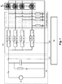
- Figure 1 shows the laser driving scheme including one pulser 20, a multiplexing platform (laser selector unit) 30, a pulse shaping bloc - for iCW operation - and a multi-color DFB laser 94.
- the system is triggered and synchronized from a common CPU board 90 which CPU board's output includes a trigger signal output 22 and a switch control output 26.
- the switch control output according to the embodiment shown comprises an-n-channel control signal, wherein n is the number of laser sections of the system.
- the respective trigger and control signal routing is shown in figure 2.
- Figure 2 further shows the laser emission 9 the sample 50 is exposed with, the detector 60 to detect the radiation from the sample 50, the data acquisition unit 94 for the detector's output for outputting the signal 8 - in the embodiment shown a digital signal - for the computer board 90.
- the respective table of the switch control signal is shown in table 1: Table 1: Switch control signals used for n DFB's Laser ID Ch 1 Ch 2 Ch 3 ... Ch n DFB 1 1 0 0 ... 0 DFB 2 0 1 0 ... 0 DFB 3 0 0 1 ... 0 ... ... ... ... ... DFB n 0 0 ... 1
- the respective Laser-ID signal for the DFB is signed as 92.
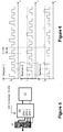
- a typical operation scheme is shown in figure 4 for a system with three laser sections.
- the parameters for a pulse duration of 5 to 10 ns and 100 averaged ramps of each 10 to 1000 ⁇ s duration - give a switch rate of 10 Hz to 1 kHz - with 100Hz in the current example - which depends also on the laser duty, the thermo-electric cooler (TEC) used and the switch dead time.
- the typical timing diagram is shown for the three sections, whereby one section is on duty only and after each switching event there is a switch dead time 56 and a thermal stabilization time 58 in which no measurement is meaningful.
- the diagram in figure 4 shows the laser sections 2 and 3 below the threshold in the first duty cycle in which only laser section 1 is lasing after the switch dead time
- a typical operation scheme is shown in figure 6 , again for a system with three laser sections.
- the typical timing diagram is shown for the three sections, whereby at a given time one section is on duty only.
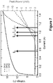
- FIG 7 the voltage and optical output power characteristics for one embodiment with a laser having three laser sections are shown.
- the definition of the active (I L1 , I L2 , I L3 ) and the subthreshold (I 0 , identical for all DFBs) laser currents for this embodiment is related to the threshold currents I th_L1 , I th_L2 I th_L3 of the respective laser sections.
Landscapes
- Physics & Mathematics (AREA)
- General Physics & Mathematics (AREA)
- Condensed Matter Physics & Semiconductors (AREA)
- Electromagnetism (AREA)
- Optics & Photonics (AREA)
- Spectroscopy & Molecular Physics (AREA)
- Investigating Or Analysing Materials By Optical Means (AREA)
- Semiconductor Lasers (AREA)
Description
- The invention is related to time-multiplexed driving of multi-colour lasers for quasi-simultaneous spectroscopic analysis including a respective system and a method.
- Simultaneous detection of multiple gas species using mid-infrared (MIR) laser spectroscopy is highly desired for numerous applications ranging from air quality monitoring, medical breath analysis, drug and explosive detection to industrial process control. Since it is often impossible to address the spectra of different gases with a single laser, state-of-the-art multi-color spectrometers have to rely on the use of several lasers with elaborate beam combining solutions. This makes them bulky, costly, and highly sensitive to optical alignment.
- As a solution to this problem, multi-color MIR lasers such as Quantum Cascade Laser (QCL) or Interband Cascade Laser (ICL) based on a heterogeneous active region and concatenated distributed feedback (DFB) gratings of different periodicities on a single waveguide ridge were proposed. Respective disclosure is published in C. Gmachl, A. Straub, R. Colombelli, F. Capasso, D.L. Sivco, A.M. Sergent et al., "Single-mode, tunable distributed-feedback and multiple-wavelength quantum cascade lasers," IEEE J. Quantum Elect. 38, 569-581 (2002); R. Blanchard et al., "Gratings with an aperiodic basis: single-mode emission in multi-wavelength lasers," New J. Phys. 13, 113023 (2011); S. Höfling et al., "Controllable Switching Between Single Modes in Two-Segment Distributed Feedback Quantum Cascade Lasers," Proceedings of IEEE International Conference on Indium Phosphide and Related Materials, Princeton, USA, pp 23-25 (2006); and
US 6148012 A by Capasso et al. Such lasers can emit light at several different wavelengths that inherently travel along the same optical path forming a single beam. As such, they don't require any beam combining optics and are ideal light sources for future multi-component trace gas spectrometers. - The reported multi-color lasers, however, were not able to operate at the multiple wavelengths sequentially, which strongly limited their application potential for laser spectroscopy. Simultaneous operation at several wavelengths leads to an overlap of the measured spectra and therefore to a cross-talk between the detected gas species. Sequential or time multiplex operation of multi-color lasers is in this sense a necessary prerequisite for their applicability in practical spectroscopy.
- Electrical separation of concatenated DFB laser sections on a single waveguide and their sequential operation was treated on a theoretical level in
WO-2013/106619 A1 . However, the first practical demonstration actually leading to an individual control of two different emission wavelengths from one laser was demonstrated by J. Faist, "20 years of quantum cascade lasers: key steps and future promises," invited presentation at 20 years QCL Anniversary Workshop, available at http://www.multimedia.ethz.ch/conferences/2014/qcl/05_thursday. InUS 2008/025539 A1 a directly modulated laser array with a microelectronic switch is disclosed. - According to a first aspect the invention has the object to provide a system including a driver for a multi-color laser enabling quasi-simultaneous detection of multiple gas species using MIR laser spectroscopy which assembly is applicable for numerous applications ranging from air quality monitoring, medical breath analysis, drug and explosive detection to industrial process control. According to a second aspect of the invention a method should be provided for quasi-simultaneous detection of multiple gas species.
- The instant invention comprises a MIR multi-color laser such as a Quantum Cascade Laser (QCL) or Interband Cascade Laser (ICL) with concatenated and electrically separated laser sections driven for quasi-simultaneous detection of multiple gas species. Driving of the respective laser sections is time-division multiplexed, such that at a given time only one wavelength is emitted. A single laser driver combined with an electronic switch is used to multiplex the laser sections. The system and the method use an optimal switching rate, which needs to be determined for a given system.
- Time division multiplexed driving essentially means, that the two or more laser sections of a multi-color laser are sequentially operated in time, i.e. at a given time, only one laser section is active, which allows detecting the gas species exhibiting absorption within the turning range of the given laser. When the measurement is completed, the first laser section is switched off and a different laser section is used to detect other gas species.
- The object of the invention is solved by a system according to
claim 1 and a method according toclaim 5. - According to the setup of the instant invention as set forth in
claim 1, an electronic switch is used which can distribute the driving current among the individual laser sections such that only one section is driven above the laser threshold and emits light, while all other sections are operated just below the threshold. Simultaneous driving of the non-active lasers below threshold minimizes the propagation loss of the lasing wavelength that gets otherwise reabsorbed in the unbiased active material. - Using one laser driver with a switch instead of two or more laser drivers hard wired to either laser section brings the following advantages: automatic synchronization of the driving pulses with the subthreshold pulses, reduced number of components for driving electronics - especially for a laser with three or more sections - resulting in a smaller footprint and lower cost for the whole system.
- It is crucial to choose the right switching rate for optimal operation of the laser, which primarily depends on the driving mode of the laser including pulsed laser operation, intra-pulse operation, intermittent-Continuous Wave (iCW) operation and Continuous Wave (CW) operation.
- Such lasers must be driven with very short pulses of typically 5-10 ns and are tuned using a subthreshold current ramp to scan the laser wavelength; the time to measure an absorption spectrum using a pulsed DFB laser (or one section of a pulsed multi-color laser) is typically 100 µs. The pulsed lasers exhibit low heat dissipation due to low duty cycle operation, but require radio-frequency compatible switches with rather long dead-times. There are several aspects to determine the optimal switching rate:
- (i) An upper boundary for the switching rate is given by the time needed to record a single spectrum, e.g. 100 µs.
- (ii) The radio-frequency compatible switches give rise to a dead-time (e.g. 300 µs), that must be added to (i). The relative effect of the dead time is reduced at lower switching rates that allow recording several spectra while the switch is in one position.
- (iii) The first few spectra after switching taken with a given laser section (e.g. 300 µs) may need to be discarded since the laser takes time to get to the thermal equilibrium. Similarly to (ii), the relative effect is reduced at low switching rates.
- (iv) Nonetheless, the switching rate should be much higher than the reaction time of the laser temperature controller. Since the heat dissipated in different laser sections may differ significantly, the thermo-electric controller (TEC) stabilizing the multi-color laser heat-sink tends to correct for the different heat dissipation at low switching rates. This produces spurious thermal chirp in the recorded spectra. At sufficiently high switching rates, the TEC senses the average heat dissipation and does not react to the change.
- (v) The switching should be fast enough so that the data acquisition can be considered "quasi-continuous".
- In pulsed operation, the interplay of aspects (ii), (iii), and (iv) leads to an optimal switching time of 10 ms during which spectra are taken, before the electronic switch selects the other laser section, and again, spectra are taken during 10 ms. This results in a complete measurement cycle of
n ∗10 ms duration where n is the number of section of the laser. - In intra-pulse operation, the laser is operated with pulses of 0.1 to 1 µs. The frequency of the iCW lasers is tuned by thermal chirp within the duration of the pulse, and a complete spectrum is measured during one pulse. Hence, the time to measure one absorption spectrum is on the order of 500 ns. The aspects (i)-(v) apply to intra-pulse operation just as to pulsed operation. Therefore, aspects (ii), (iii) and (iv) again result in an optimal switching time of approximately 10 ms.
- iCW lasers are driven with long pulses of 2 to 200 µs duration and can be operated at high duty cycles of up to 50%. The frequency of the iCW lasers is tuned by thermal chirp within the duration of the pulse, and, hence, the time to measure one absorption spectrum is on the order of 1 µs. The switching hardware available for 100 µs pulses has much shorter death time than for pulsed lasers, being of the order of 1 µs, i.e. shorter than the time to record one spectrum.
- When determining the optimal switching time, condition (ii) and (iii) don't apply and the optimal switching rate is determined by (i). In an iCW multi-wavelength experiment the optimal switching time is therefore given by the time to record a single spectrum.
- In CW laser operation the laser is tuned with a current ramp at a typical rate of 1 to 10 kHz, and concerning the heat dissipation, switching hardware and times to record one single spectrum, they are analogous to the iCW lasers. The optimal switching rate is therefore also determined by condition (i).
- Advantageous details in respect to the system and the method according to the instant invention are defined by the dependent claims.
- The aforementioned elements as well as those claimed and described in the following exemplary embodiments, to be used according to the invention, are not subject to any particular conditions by way of exclusion in terms of their size, shape, use of material and technical design, with the result that the selection criteria known in the respective field of application can be used without restrictions. It should be noted that all means used to implement the invention are not limited to a particular design.
- Examples of the laser system and its operation will henceforth be described in more detail by reference to the drawings, wherein are shown:
- Figure 1
- is a block diagram of the laser driving scheme according to a preferred embodiment of the instant invention;
- Figure 2
- is a trigger and control signal routing for a typical application in MIR laser spectroscopy according to the embodiment of
figure 1 ; - Figure 3
- is the driving scheme for a pulsed operation of the system of
figures 1 and2 , shown in an embodiment with a three-color laser. - Figure 4
- shows the resulting current for the three sections of the embodiment of
figure 3 ; - Figure 5
- is the driving scheme for an iCW operation of the system of
figures 1 and2 , shown in an embodiment with a three-color laser. - Figure 6
- shows the resulting current for the three sections of the embodiment of
figure 5 ; - Figure 7
- shows the diagram of the voltage and optimal power characteristic for an embodiment with a three color laser.
-
Figure 1 shows the laser driving scheme including onepulser 20, a multiplexing platform (laser selector unit) 30, a pulse shaping bloc - for iCW operation - and amulti-color DFB laser 94. The system is triggered and synchronized from acommon CPU board 90 which CPU board's output includes atrigger signal output 22 and aswitch control output 26. The switch control output according to the embodiment shown comprises an-n-channel control signal, wherein n is the number of laser sections of the system. The respective trigger and control signal routing is shown infigure 2. Figure 2 further shows thelaser emission 9 thesample 50 is exposed with, thedetector 60 to detect the radiation from thesample 50, thedata acquisition unit 94 for the detector's output for outputting the signal 8 - in the embodiment shown a digital signal - for thecomputer board 90. The respective table of the switch control signal is shown in table 1:Table 1: Switch control signals used for n DFB's Laser ID Ch 1 Ch 2Ch 3... Ch n DFB 1 1 0 0 ... 0 DFB 20 1 0 ... 0 DFB 30 0 1 ... 0 ... ... ... ... ... ... DFB n 0 0 0 ... 1 - For pulsed operation a typical operation scheme is shown in
figure 4 for a system with three laser sections. The parameters for a pulse duration of 5 to 10 ns and 100 averaged ramps of each 10 to 1000 µs duration - give a switch rate of 10 Hz to 1 kHz - with 100Hz in the current example - which depends also on the laser duty, the thermo-electric cooler (TEC) used and the switch dead time. Infigure 4 the typical timing diagram is shown for the three sections, whereby one section is on duty only and after each switching event there is a switchdead time 56 and athermal stabilization time 58 in which no measurement is meaningful. The diagram infigure 4 shows thelaser sections laser section 1 is lasing after the switch dead time - For Intermittent-Continuous Wave (iCW) operation a typical operation scheme is shown in
figure 6 , again for a system with three laser sections. The parameters for a pulse duration of 2 µs to 200 µs - dependent on the driver, the data acquisition and the laser - a duty of 1% to 50% - depending on the particular application and the power saving requirements - and a switch rate of 500 Hz to 250 kHz - with 10 kHz in the current example - depending on the laser duty, the thermo-electric cooler (TEC) used and the switch dead time. Infigure 6 the typical timing diagram is shown for the three sections, whereby at a given time one section is on duty only. - In
figure 7 the voltage and optical output power characteristics for one embodiment with a laser having three laser sections are shown. The definition of the active (IL1, IL2, IL3) and the subthreshold (I0, identical for all DFBs) laser currents for this embodiment is related to the threshold currents Ith_L1, Ith_L2 Ith_L3 of the respective laser sections. The selected operation parameters are IL1 = 1.1 Ith_L1, IL2 = 1.1 Ith_L2 and IL3= 1.1 Ith_L3 for the active laser current and I0 = 0.7 min (Ith_L1, Ith_L2 Ith_L3) for the subthreshold current. -
- 4
- Laser
- 8
- Signal
- 9
- Emission
- 20
- Pulse generating means
- 22
- Laser Trigger
- 26
- Switch Control (n-channel)
- 30
- Multiplex Platform/Laser selector unit
- 50
- Sample
- 56
- Switch dead time
- 58
- Thermal stabilization time
- 60
- Detector
- 70
- Signal generator subsystem
- 90
- CPU-board
- 92
- Laser ID
- 94
- Data acquisition subsystem
Claims (13)
- A laser system for laser spectroscopy, including a mid-infrared, MIR, multi-color laser, laser driver means for said multi-color laser enabling simultaneous detection of a sample, preferably a multiple gas species, wherein said MIR multi-color laser comprises concatenated and electrically separated laser sections,
wherein said laser driver means comprise pulse generating means and are designed to drive the respective laser sections in a time-division multiplexed mode, such that the laser sections are sequentially operated in time and at a given time only one wavelength is emitted,
characterized in that
the laser driver means comprises a laser selector unit as a multiplexing platform and
an electronic switch is configured for distributing the driving current among the individual laser sections such that only one section is driven above the laser threshold and emits light, while all other sections are operated below the threshold. - The laser system according to claim 1 characterized in that said MIR multi-color laser is a Quantum Cascade Laser or Interband Cascade Laser.
- The laser system according to claim 1 or 2, characterized in that the system further comprises detector means for detecting the laser radiation after passing the sample, data acquisition means for acquisition of the signals detected by the detector means and computer means for evaluating the data from the data acquisition means and providing a selection signal for the multiplexing of the laser selector unit.
- The laser system according to claim 3, characterized in that the computer means is designed to further output a trigger signal triggering the pulse generating means.
- A method for operation of a laser system for mid-infrared, MIR, laser spectroscopy, said laser system including a MIR multi-color laser, laser driver means for said multi-color laser, wherein said MIR multi-color laser comprises concatenated and electrically separated laser sections, wherein said laser driver means comprise pulse generating means and are designed to drive the respective laser sections in a time-division multiplexed mode, such that the laser sections are sequentially operated in time and at a given time only one wavelength is emitted, wherein the laser driver means comprises a laser selector unit, preferably a laser system according to any of claims 1 to 4, said method comprising
distributing the driving current among the individual laser sections such that only one section is driven above the laser threshold and emits light, while the other laser sections are operated below the threshold by means of said laser selector unit. - The method according to claim 5 characterized in that said MIR multi-colour laser is a Quantum Cascade Laser or Interband Cascade Laser.
- The method according to claim 5 or 6, characterized in that detector means detecting the laser radiation after passing the sample, data acquisition means acquiring the signals detected by the detector means and computer means evaluating the data from the data acquisition means and outputting a selection signal for the multiplexing of the laser selector unit, thereby enabling simultaneous detection of a sample, preferably a multiple gas species.
- The method according to claim 7, characterized in that the computer means further outputs a trigger signal triggering the laser.
- The method according to any of claims 7 or 8 with a pulsed laser operation, characterized in that the pulse duration is in the range of 5 to 10 ns, a ramp in the range of 10 to 1000 µs, and the switch rate in the range of 10 Hz to 200 Hz, preferably about 100Hz whereby one section is on duty only and after switching events there is a switch dead time and a thermal stabilization time in which no measurement is performed.
- The method according to any of claims 7 or 8 with an Intermittent-Continuous Wave operation, iCW, characterized by a pulse duration of 2 µs to 200 µs, a duty cycle of 1% to 50% and a switch rate of 500 Hz to 250 kHz, preferably of about 10 kHz.
- The method according to claim 10 with an intra-pulse operation, characterized in that pulse duration is in the range of 0.1 to 1 µs, wherein the frequency of the iCW lasers is within the duration of the pulse, and preferably a complete spectrum is measured during one pulse.
- The method of claim 11, characterized in that the switching time is approximately 10 ms.
- The method according to any of claims 7 or 8 with a Continuous Wave operation, characterized in that the current ramp is in a range 1 to 10 kHz.
Priority Applications (1)
| Application Number | Priority Date | Filing Date | Title |
|---|---|---|---|
| EP14166907.7A EP2940808B1 (en) | 2014-05-02 | 2014-05-02 | Time-multiplexed driving of multi-colour lasers for quasi-simultaneous spectroscopic analysis |
Applications Claiming Priority (1)
| Application Number | Priority Date | Filing Date | Title |
|---|---|---|---|
| EP14166907.7A EP2940808B1 (en) | 2014-05-02 | 2014-05-02 | Time-multiplexed driving of multi-colour lasers for quasi-simultaneous spectroscopic analysis |
Publications (2)
| Publication Number | Publication Date |
|---|---|
| EP2940808A1 EP2940808A1 (en) | 2015-11-04 |
| EP2940808B1 true EP2940808B1 (en) | 2019-11-27 |
Family
ID=50628684
Family Applications (1)
| Application Number | Title | Priority Date | Filing Date |
|---|---|---|---|
| EP14166907.7A Active EP2940808B1 (en) | 2014-05-02 | 2014-05-02 | Time-multiplexed driving of multi-colour lasers for quasi-simultaneous spectroscopic analysis |
Country Status (1)
| Country | Link |
|---|---|
| EP (1) | EP2940808B1 (en) |
Cited By (1)
| Publication number | Priority date | Publication date | Assignee | Title |
|---|---|---|---|---|
| EP3974808A1 (en) | 2020-09-25 | 2022-03-30 | MIRO Analytical AG | Gas analyser apparatus and method |
Families Citing this family (3)
| Publication number | Priority date | Publication date | Assignee | Title |
|---|---|---|---|---|
| RU2682061C2 (en) * | 2014-12-23 | 2019-03-14 | Джон Цинк Компани, ЛЛК | Tdlas architecture for widely spaced wavelengths |
| CN119688645B (en) * | 2024-12-17 | 2025-10-31 | 北京雪迪龙科技股份有限公司 | A cavity ring-down spectroscopy multi-gas detection device and method |
| CN119845899B (en) * | 2024-12-27 | 2025-11-28 | 厦门大学 | Light source wavelength selection and gas concentration detection method for mixed gas distributed sensing system with overlapped absorption spectrums |
Family Cites Families (3)
| Publication number | Priority date | Publication date | Assignee | Title |
|---|---|---|---|---|
| US6148012A (en) | 1998-10-21 | 2000-11-14 | Lucent Technologies Inc. | Multiple wavelength quantum cascade light source |
| US8000368B2 (en) * | 2006-07-26 | 2011-08-16 | Santur Corporation | Modulated semiconductor DFB laser array with a MEMS-based RF switch |
| EP2803122B1 (en) | 2012-01-13 | 2020-06-10 | Thorlabs Quantum Electronics, Inc. | Mid-ir multiwavelength concatenated distributed-feedback laser with an active core made of cascaded stages |
-
2014
- 2014-05-02 EP EP14166907.7A patent/EP2940808B1/en active Active
Non-Patent Citations (1)
| Title |
|---|
| None * |
Cited By (2)
| Publication number | Priority date | Publication date | Assignee | Title |
|---|---|---|---|---|
| EP3974808A1 (en) | 2020-09-25 | 2022-03-30 | MIRO Analytical AG | Gas analyser apparatus and method |
| WO2022063740A1 (en) | 2020-09-25 | 2022-03-31 | Miro Analytical Ag | Gas analyser apparatus and method |
Also Published As
| Publication number | Publication date |
|---|---|
| EP2940808A1 (en) | 2015-11-04 |
Similar Documents
| Publication | Publication Date | Title |
|---|---|---|
| EP2940808A1 (en) | Time-multiplexed driving of multi-colour lasers for quasi-simultaneous spectroscopic analysis | |
| EP3235078B1 (en) | Laser sensor module | |
| EP0813272A2 (en) | Wavelength-changeable light source capable of changing wavelength of output light, optical communication network using the same and wavelength control method for controlling wavelength of output light of the same | |
| CN112544020B (en) | Manufacturing method of laser diode array device, laser light emitting circuit and distance measuring device | |
| EP3189565A1 (en) | Spectroscopic detection using a tunable frequency comb | |
| CN1659429A (en) | Device and method for semiconductor diode laser spectrometer | |
| US8928802B2 (en) | Method and apparatus for producing high dynamic range (HDR) pictures, and exposure apparatuses for use therein | |
| US9142937B2 (en) | Wavelength referencing by monitoring a voltage across a laser diode | |
| KR102299156B1 (en) | Time measurement device, time measurement method, light-emission-lifetime measurement device, and light-emission-lifetime measurement method | |
| US20090194697A1 (en) | Apparatus for use in operator training with, and the testing and evaluation of, infrared sensors which are for missile detection | |
| Romadhon et al. | Longitudinal modes evolution of a GaN-based blue laser diode | |
| WO2010062752A1 (en) | Spectrometers utilizing mid infrared ultra broadband high brightness light sources | |
| Lutz et al. | Accumulation mode laser range-gated viewing in the eye-safe spectral region | |
| Klehr et al. | Pico-and nanosecond investigations of the lateral nearfield of broad area lasers under pulsed high-current excitation | |
| Hallman et al. | Asymmetric waveguide laser diode operated in gain switching mode with high-power optical pulse generation | |
| CN110662979B (en) | Transmitter unit for emitting radiation into the surrounding environment | |
| Liu et al. | Observation of transient spectra and mode partition noise of injection lasers | |
| Maiwald et al. | Dual-wavelength master oscillator power amplifier diode-laser system at 785 nm | |
| Patel et al. | Quantum cascade lasers: 25 years after the first demonstration | |
| Kurobe et al. | Tunable laser source for fast wavelength switching using a short-cavity DBR laser packaged with wavelength locker | |
| US10295407B2 (en) | Light source having a controllable spectrum | |
| Melkonian et al. | Time-resolved spectral characterization of a pulsed external-cavity quantum cascade laser | |
| Vallon et al. | External cavity coherent quantum cascade laser array | |
| Toor et al. | Temporal wavelength multiplexing of a quantum cascade laser | |
| US20230307886A1 (en) | Wavelength stabilization of pulsed lasers |
Legal Events
| Date | Code | Title | Description |
|---|---|---|---|
| PUAI | Public reference made under article 153(3) epc to a published international application that has entered the european phase |
Free format text: ORIGINAL CODE: 0009012 |
|
| AK | Designated contracting states |
Kind code of ref document: A1 Designated state(s): AL AT BE BG CH CY CZ DE DK EE ES FI FR GB GR HR HU IE IS IT LI LT LU LV MC MK MT NL NO PL PT RO RS SE SI SK SM TR |
|
| AX | Request for extension of the european patent |
Extension state: BA ME |
|
| 17P | Request for examination filed |
Effective date: 20160330 |
|
| RBV | Designated contracting states (corrected) |
Designated state(s): AL AT BE BG CH CY CZ DE DK EE ES FI FR GB GR HR HU IE IS IT LI LT LU LV MC MK MT NL NO PL PT RO RS SE SI SK SM TR |
|
| GRAP | Despatch of communication of intention to grant a patent |
Free format text: ORIGINAL CODE: EPIDOSNIGR1 |
|
| STAA | Information on the status of an ep patent application or granted ep patent |
Free format text: STATUS: GRANT OF PATENT IS INTENDED |
|
| INTG | Intention to grant announced |
Effective date: 20190614 |
|
| GRAS | Grant fee paid |
Free format text: ORIGINAL CODE: EPIDOSNIGR3 |
|
| GRAA | (expected) grant |
Free format text: ORIGINAL CODE: 0009210 |
|
| STAA | Information on the status of an ep patent application or granted ep patent |
Free format text: STATUS: THE PATENT HAS BEEN GRANTED |
|
| AK | Designated contracting states |
Kind code of ref document: B1 Designated state(s): AL AT BE BG CH CY CZ DE DK EE ES FI FR GB GR HR HU IE IS IT LI LT LU LV MC MK MT NL NO PL PT RO RS SE SI SK SM TR |
|
| REG | Reference to a national code |
Ref country code: GB Ref legal event code: FG4D |
|
| REG | Reference to a national code |
Ref country code: CH Ref legal event code: EP |
|
| REG | Reference to a national code |
Ref country code: AT Ref legal event code: REF Ref document number: 1207789 Country of ref document: AT Kind code of ref document: T Effective date: 20191215 |
|
| REG | Reference to a national code |
Ref country code: DE Ref legal event code: R096 Ref document number: 602014057383 Country of ref document: DE |
|
| REG | Reference to a national code |
Ref country code: IE Ref legal event code: FG4D |
|
| REG | Reference to a national code |
Ref country code: NL Ref legal event code: MP Effective date: 20191127 |
|
| REG | Reference to a national code |
Ref country code: LT Ref legal event code: MG4D |
|
| PG25 | Lapsed in a contracting state [announced via postgrant information from national office to epo] |
Ref country code: FI Free format text: LAPSE BECAUSE OF FAILURE TO SUBMIT A TRANSLATION OF THE DESCRIPTION OR TO PAY THE FEE WITHIN THE PRESCRIBED TIME-LIMIT Effective date: 20191127 Ref country code: SE Free format text: LAPSE BECAUSE OF FAILURE TO SUBMIT A TRANSLATION OF THE DESCRIPTION OR TO PAY THE FEE WITHIN THE PRESCRIBED TIME-LIMIT Effective date: 20191127 Ref country code: LV Free format text: LAPSE BECAUSE OF FAILURE TO SUBMIT A TRANSLATION OF THE DESCRIPTION OR TO PAY THE FEE WITHIN THE PRESCRIBED TIME-LIMIT Effective date: 20191127 Ref country code: GR Free format text: LAPSE BECAUSE OF FAILURE TO SUBMIT A TRANSLATION OF THE DESCRIPTION OR TO PAY THE FEE WITHIN THE PRESCRIBED TIME-LIMIT Effective date: 20200228 Ref country code: BG Free format text: LAPSE BECAUSE OF FAILURE TO SUBMIT A TRANSLATION OF THE DESCRIPTION OR TO PAY THE FEE WITHIN THE PRESCRIBED TIME-LIMIT Effective date: 20200227 Ref country code: LT Free format text: LAPSE BECAUSE OF FAILURE TO SUBMIT A TRANSLATION OF THE DESCRIPTION OR TO PAY THE FEE WITHIN THE PRESCRIBED TIME-LIMIT Effective date: 20191127 Ref country code: NO Free format text: LAPSE BECAUSE OF FAILURE TO SUBMIT A TRANSLATION OF THE DESCRIPTION OR TO PAY THE FEE WITHIN THE PRESCRIBED TIME-LIMIT Effective date: 20200227 Ref country code: NL Free format text: LAPSE BECAUSE OF FAILURE TO SUBMIT A TRANSLATION OF THE DESCRIPTION OR TO PAY THE FEE WITHIN THE PRESCRIBED TIME-LIMIT Effective date: 20191127 |
|
| PG25 | Lapsed in a contracting state [announced via postgrant information from national office to epo] |
Ref country code: HR Free format text: LAPSE BECAUSE OF FAILURE TO SUBMIT A TRANSLATION OF THE DESCRIPTION OR TO PAY THE FEE WITHIN THE PRESCRIBED TIME-LIMIT Effective date: 20191127 Ref country code: IS Free format text: LAPSE BECAUSE OF FAILURE TO SUBMIT A TRANSLATION OF THE DESCRIPTION OR TO PAY THE FEE WITHIN THE PRESCRIBED TIME-LIMIT Effective date: 20200327 Ref country code: RS Free format text: LAPSE BECAUSE OF FAILURE TO SUBMIT A TRANSLATION OF THE DESCRIPTION OR TO PAY THE FEE WITHIN THE PRESCRIBED TIME-LIMIT Effective date: 20191127 |
|
| PG25 | Lapsed in a contracting state [announced via postgrant information from national office to epo] |
Ref country code: AL Free format text: LAPSE BECAUSE OF FAILURE TO SUBMIT A TRANSLATION OF THE DESCRIPTION OR TO PAY THE FEE WITHIN THE PRESCRIBED TIME-LIMIT Effective date: 20191127 |
|
| PG25 | Lapsed in a contracting state [announced via postgrant information from national office to epo] |
Ref country code: EE Free format text: LAPSE BECAUSE OF FAILURE TO SUBMIT A TRANSLATION OF THE DESCRIPTION OR TO PAY THE FEE WITHIN THE PRESCRIBED TIME-LIMIT Effective date: 20191127 Ref country code: PT Free format text: LAPSE BECAUSE OF FAILURE TO SUBMIT A TRANSLATION OF THE DESCRIPTION OR TO PAY THE FEE WITHIN THE PRESCRIBED TIME-LIMIT Effective date: 20200419 Ref country code: RO Free format text: LAPSE BECAUSE OF FAILURE TO SUBMIT A TRANSLATION OF THE DESCRIPTION OR TO PAY THE FEE WITHIN THE PRESCRIBED TIME-LIMIT Effective date: 20191127 Ref country code: DK Free format text: LAPSE BECAUSE OF FAILURE TO SUBMIT A TRANSLATION OF THE DESCRIPTION OR TO PAY THE FEE WITHIN THE PRESCRIBED TIME-LIMIT Effective date: 20191127 Ref country code: CZ Free format text: LAPSE BECAUSE OF FAILURE TO SUBMIT A TRANSLATION OF THE DESCRIPTION OR TO PAY THE FEE WITHIN THE PRESCRIBED TIME-LIMIT Effective date: 20191127 Ref country code: ES Free format text: LAPSE BECAUSE OF FAILURE TO SUBMIT A TRANSLATION OF THE DESCRIPTION OR TO PAY THE FEE WITHIN THE PRESCRIBED TIME-LIMIT Effective date: 20191127 |
|
| REG | Reference to a national code |
Ref country code: DE Ref legal event code: R097 Ref document number: 602014057383 Country of ref document: DE |
|
| PG25 | Lapsed in a contracting state [announced via postgrant information from national office to epo] |
Ref country code: SK Free format text: LAPSE BECAUSE OF FAILURE TO SUBMIT A TRANSLATION OF THE DESCRIPTION OR TO PAY THE FEE WITHIN THE PRESCRIBED TIME-LIMIT Effective date: 20191127 Ref country code: SM Free format text: LAPSE BECAUSE OF FAILURE TO SUBMIT A TRANSLATION OF THE DESCRIPTION OR TO PAY THE FEE WITHIN THE PRESCRIBED TIME-LIMIT Effective date: 20191127 |
|
| REG | Reference to a national code |
Ref country code: AT Ref legal event code: MK05 Ref document number: 1207789 Country of ref document: AT Kind code of ref document: T Effective date: 20191127 |
|
| PLBE | No opposition filed within time limit |
Free format text: ORIGINAL CODE: 0009261 |
|
| STAA | Information on the status of an ep patent application or granted ep patent |
Free format text: STATUS: NO OPPOSITION FILED WITHIN TIME LIMIT |
|
| 26N | No opposition filed |
Effective date: 20200828 |
|
| PG25 | Lapsed in a contracting state [announced via postgrant information from national office to epo] |
Ref country code: AT Free format text: LAPSE BECAUSE OF FAILURE TO SUBMIT A TRANSLATION OF THE DESCRIPTION OR TO PAY THE FEE WITHIN THE PRESCRIBED TIME-LIMIT Effective date: 20191127 Ref country code: SI Free format text: LAPSE BECAUSE OF FAILURE TO SUBMIT A TRANSLATION OF THE DESCRIPTION OR TO PAY THE FEE WITHIN THE PRESCRIBED TIME-LIMIT Effective date: 20191127 Ref country code: PL Free format text: LAPSE BECAUSE OF FAILURE TO SUBMIT A TRANSLATION OF THE DESCRIPTION OR TO PAY THE FEE WITHIN THE PRESCRIBED TIME-LIMIT Effective date: 20191127 |
|
| PG25 | Lapsed in a contracting state [announced via postgrant information from national office to epo] |
Ref country code: IT Free format text: LAPSE BECAUSE OF FAILURE TO SUBMIT A TRANSLATION OF THE DESCRIPTION OR TO PAY THE FEE WITHIN THE PRESCRIBED TIME-LIMIT Effective date: 20191127 Ref country code: MC Free format text: LAPSE BECAUSE OF FAILURE TO SUBMIT A TRANSLATION OF THE DESCRIPTION OR TO PAY THE FEE WITHIN THE PRESCRIBED TIME-LIMIT Effective date: 20191127 |
|
| REG | Reference to a national code |
Ref country code: BE Ref legal event code: MM Effective date: 20200531 |
|
| PG25 | Lapsed in a contracting state [announced via postgrant information from national office to epo] |
Ref country code: LU Free format text: LAPSE BECAUSE OF NON-PAYMENT OF DUE FEES Effective date: 20200502 |
|
| PG25 | Lapsed in a contracting state [announced via postgrant information from national office to epo] |
Ref country code: IE Free format text: LAPSE BECAUSE OF NON-PAYMENT OF DUE FEES Effective date: 20200502 |
|
| PG25 | Lapsed in a contracting state [announced via postgrant information from national office to epo] |
Ref country code: BE Free format text: LAPSE BECAUSE OF NON-PAYMENT OF DUE FEES Effective date: 20200531 |
|
| PG25 | Lapsed in a contracting state [announced via postgrant information from national office to epo] |
Ref country code: TR Free format text: LAPSE BECAUSE OF FAILURE TO SUBMIT A TRANSLATION OF THE DESCRIPTION OR TO PAY THE FEE WITHIN THE PRESCRIBED TIME-LIMIT Effective date: 20191127 Ref country code: MT Free format text: LAPSE BECAUSE OF FAILURE TO SUBMIT A TRANSLATION OF THE DESCRIPTION OR TO PAY THE FEE WITHIN THE PRESCRIBED TIME-LIMIT Effective date: 20191127 Ref country code: CY Free format text: LAPSE BECAUSE OF FAILURE TO SUBMIT A TRANSLATION OF THE DESCRIPTION OR TO PAY THE FEE WITHIN THE PRESCRIBED TIME-LIMIT Effective date: 20191127 |
|
| PG25 | Lapsed in a contracting state [announced via postgrant information from national office to epo] |
Ref country code: MK Free format text: LAPSE BECAUSE OF FAILURE TO SUBMIT A TRANSLATION OF THE DESCRIPTION OR TO PAY THE FEE WITHIN THE PRESCRIBED TIME-LIMIT Effective date: 20191127 |
|
| PGFP | Annual fee paid to national office [announced via postgrant information from national office to epo] |
Ref country code: GB Payment date: 20220520 Year of fee payment: 9 Ref country code: FR Payment date: 20220523 Year of fee payment: 9 Ref country code: DE Payment date: 20220519 Year of fee payment: 9 |
|
| PGFP | Annual fee paid to national office [announced via postgrant information from national office to epo] |
Ref country code: CH Payment date: 20220426 Year of fee payment: 9 |
|
| REG | Reference to a national code |
Ref country code: DE Ref legal event code: R119 Ref document number: 602014057383 Country of ref document: DE |
|
| REG | Reference to a national code |
Ref country code: CH Ref legal event code: PL |
|
| GBPC | Gb: european patent ceased through non-payment of renewal fee |
Effective date: 20230502 |
|
| PG25 | Lapsed in a contracting state [announced via postgrant information from national office to epo] |
Ref country code: LI Free format text: LAPSE BECAUSE OF NON-PAYMENT OF DUE FEES Effective date: 20230531 Ref country code: CH Free format text: LAPSE BECAUSE OF NON-PAYMENT OF DUE FEES Effective date: 20230531 |
|
| PG25 | Lapsed in a contracting state [announced via postgrant information from national office to epo] |
Ref country code: DE Free format text: LAPSE BECAUSE OF NON-PAYMENT OF DUE FEES Effective date: 20231201 Ref country code: GB Free format text: LAPSE BECAUSE OF NON-PAYMENT OF DUE FEES Effective date: 20230502 |
|
| PG25 | Lapsed in a contracting state [announced via postgrant information from national office to epo] |
Ref country code: FR Free format text: LAPSE BECAUSE OF NON-PAYMENT OF DUE FEES Effective date: 20230531 |