EP2940757A1 - Battery module and battery pack - Google Patents
Battery module and battery pack Download PDFInfo
- Publication number
- EP2940757A1 EP2940757A1 EP13867690.3A EP13867690A EP2940757A1 EP 2940757 A1 EP2940757 A1 EP 2940757A1 EP 13867690 A EP13867690 A EP 13867690A EP 2940757 A1 EP2940757 A1 EP 2940757A1
- Authority
- EP
- European Patent Office
- Prior art keywords
- case
- battery module
- main surface
- cell unit
- cell
- Prior art date
- Legal status (The legal status is an assumption and is not a legal conclusion. Google has not performed a legal analysis and makes no representation as to the accuracy of the status listed.)
- Granted
Links
Images





Classifications
-
- H—ELECTRICITY
- H01—ELECTRIC ELEMENTS
- H01M—PROCESSES OR MEANS, e.g. BATTERIES, FOR THE DIRECT CONVERSION OF CHEMICAL ENERGY INTO ELECTRICAL ENERGY
- H01M50/00—Constructional details or processes of manufacture of the non-active parts of electrochemical cells other than fuel cells, e.g. hybrid cells
- H01M50/20—Mountings; Secondary casings or frames; Racks, modules or packs; Suspension devices; Shock absorbers; Transport or carrying devices; Holders
- H01M50/262—Mountings; Secondary casings or frames; Racks, modules or packs; Suspension devices; Shock absorbers; Transport or carrying devices; Holders with fastening means, e.g. locks
- H01M50/264—Mountings; Secondary casings or frames; Racks, modules or packs; Suspension devices; Shock absorbers; Transport or carrying devices; Holders with fastening means, e.g. locks for cells or batteries, e.g. straps, tie rods or peripheral frames
-
- H—ELECTRICITY
- H01—ELECTRIC ELEMENTS
- H01M—PROCESSES OR MEANS, e.g. BATTERIES, FOR THE DIRECT CONVERSION OF CHEMICAL ENERGY INTO ELECTRICAL ENERGY
- H01M50/00—Constructional details or processes of manufacture of the non-active parts of electrochemical cells other than fuel cells, e.g. hybrid cells
- H01M50/20—Mountings; Secondary casings or frames; Racks, modules or packs; Suspension devices; Shock absorbers; Transport or carrying devices; Holders
- H01M50/204—Racks, modules or packs for multiple batteries or multiple cells
- H01M50/207—Racks, modules or packs for multiple batteries or multiple cells characterised by their shape
- H01M50/211—Racks, modules or packs for multiple batteries or multiple cells characterised by their shape adapted for pouch cells
-
- H—ELECTRICITY
- H01—ELECTRIC ELEMENTS
- H01M—PROCESSES OR MEANS, e.g. BATTERIES, FOR THE DIRECT CONVERSION OF CHEMICAL ENERGY INTO ELECTRICAL ENERGY
- H01M50/00—Constructional details or processes of manufacture of the non-active parts of electrochemical cells other than fuel cells, e.g. hybrid cells
- H01M50/20—Mountings; Secondary casings or frames; Racks, modules or packs; Suspension devices; Shock absorbers; Transport or carrying devices; Holders
- H01M50/289—Mountings; Secondary casings or frames; Racks, modules or packs; Suspension devices; Shock absorbers; Transport or carrying devices; Holders characterised by spacing elements or positioning means within frames, racks or packs
- H01M50/291—Mountings; Secondary casings or frames; Racks, modules or packs; Suspension devices; Shock absorbers; Transport or carrying devices; Holders characterised by spacing elements or positioning means within frames, racks or packs characterised by their shape
-
- H—ELECTRICITY
- H01—ELECTRIC ELEMENTS
- H01M—PROCESSES OR MEANS, e.g. BATTERIES, FOR THE DIRECT CONVERSION OF CHEMICAL ENERGY INTO ELECTRICAL ENERGY
- H01M2220/00—Batteries for particular applications
- H01M2220/20—Batteries in motive systems, e.g. vehicle, ship, plane
-
- H—ELECTRICITY
- H01—ELECTRIC ELEMENTS
- H01M—PROCESSES OR MEANS, e.g. BATTERIES, FOR THE DIRECT CONVERSION OF CHEMICAL ENERGY INTO ELECTRICAL ENERGY
- H01M50/00—Constructional details or processes of manufacture of the non-active parts of electrochemical cells other than fuel cells, e.g. hybrid cells
- H01M50/10—Primary casings; Jackets or wrappings
- H01M50/102—Primary casings; Jackets or wrappings characterised by their shape or physical structure
- H01M50/105—Pouches or flexible bags
-
- H—ELECTRICITY
- H01—ELECTRIC ELEMENTS
- H01M—PROCESSES OR MEANS, e.g. BATTERIES, FOR THE DIRECT CONVERSION OF CHEMICAL ENERGY INTO ELECTRICAL ENERGY
- H01M50/00—Constructional details or processes of manufacture of the non-active parts of electrochemical cells other than fuel cells, e.g. hybrid cells
- H01M50/50—Current conducting connections for cells or batteries
- H01M50/543—Terminals
- H01M50/547—Terminals characterised by the disposition of the terminals on the cells
- H01M50/55—Terminals characterised by the disposition of the terminals on the cells on the same side of the cell
-
- H—ELECTRICITY
- H01—ELECTRIC ELEMENTS
- H01M—PROCESSES OR MEANS, e.g. BATTERIES, FOR THE DIRECT CONVERSION OF CHEMICAL ENERGY INTO ELECTRICAL ENERGY
- H01M50/00—Constructional details or processes of manufacture of the non-active parts of electrochemical cells other than fuel cells, e.g. hybrid cells
- H01M50/50—Current conducting connections for cells or batteries
- H01M50/543—Terminals
- H01M50/552—Terminals characterised by their shape
- H01M50/553—Terminals adapted for prismatic, pouch or rectangular cells
- H01M50/557—Plate-shaped terminals
-
- Y—GENERAL TAGGING OF NEW TECHNOLOGICAL DEVELOPMENTS; GENERAL TAGGING OF CROSS-SECTIONAL TECHNOLOGIES SPANNING OVER SEVERAL SECTIONS OF THE IPC; TECHNICAL SUBJECTS COVERED BY FORMER USPC CROSS-REFERENCE ART COLLECTIONS [XRACs] AND DIGESTS
- Y02—TECHNOLOGIES OR APPLICATIONS FOR MITIGATION OR ADAPTATION AGAINST CLIMATE CHANGE
- Y02E—REDUCTION OF GREENHOUSE GAS [GHG] EMISSIONS, RELATED TO ENERGY GENERATION, TRANSMISSION OR DISTRIBUTION
- Y02E60/00—Enabling technologies; Technologies with a potential or indirect contribution to GHG emissions mitigation
- Y02E60/10—Energy storage using batteries
Definitions
- the present invention relates to a battery module and a battery pack.
- a battery module is structured by enclosing a cell unit including a laminate of several such unit cells stacked on one another by upper and lower cases. Moreover, by connecting multiple battery modules configured in this way in series or in parallel, a battery pack is formed, which corresponds to a desired current, voltage, or capacity (for example, see Patent Document 1).
- Patent Document 1 JP 2003-203615 JP
- the present invention has been made to solve the above problem, and an object thereof is to provide a battery module and a battery pack which may be easily assembled and may be prevented from being damaged when assembling.
- a battery module comprises a cell unit having at least one unit cell, and first and second cases, which are paired to enclose and house the cell unit.
- Each of the first and second cases has a main surface and either one side surface bent at one end of and extending in a direction away from the main surface or a pair of side surfaces bent at both ends of and extending in a direction away from the main surface with different extension lengths from each other.
- the cell unit is relatively moved to the first case until abutting against a side surface bent at and extending from one end of the main surface or a side surface with longer extension length of the pair of side surfaces, in a direction perpendicular to the surface(s). Then, the cell unit is relatively moved to the first case in a direction of extension of the side surface by using the side surface as a guide until abutting against the side surface bent at and extending from one end of the main surface or the side surface with longer extension length of the pair of side surfaces. Then, by moving the cell unit relatively to the second case in a direction of extension of the side surface using the side surface as a guide, the cell unit may be covered by the second case. Therefore, it is possible to provide a battery module which may be easily assembled and is capable of being prevented from damage during assembly process.
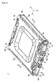
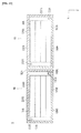
- FIG. 1 is a perspective view of a battery module 1 pertaining to a first embodiment of the present invention.
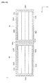
- FIG. 2 is a schematic sectional view taken along line 2-2 of FIG. 1 .
- a cell unit 30 is described by a block body.
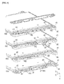
- FIG. 3 is a perspective view of a cell unit 30 of the battery module 1.
- the schematic sectional views shown in FIGS. 8 to 16 below, are those similar to FIG. 2 taken along line 2-2 of FIG. 1 .
- a battery module 1 pertaining to the first embodiment according to the present invention is generally shown in FIGS. 1-3 , and is provided with a cell unit 30 with four cells 10 (10A to 10D), and a first and second cases 100, 200 which are paired to enclose the cell unit 30.
- Each of the first and second cases 100, 200 includes a main surface 101, 201 and a side surface 102, 103 bent at one end of the main surface 101, 201 and extending in a direction away from the main surface 101, 201. Below, a description is give in detail.
- the battery module 1 includes a cell unit 30 having four unit cells 10 (10A ⁇ 10D), a pair of the first and second cases 100, 200 for accommodating or housing the cell unit 30 so as to enclose the cell unit.
- the battery module 1 is further provided with, in the main surface 101, 201 of the and second cases 100, 200, a first through hole 26 extending in an extension direction Z of the side surfaces 102, 202 and a fastening mechanism 70 which is inserted into a second through hole 41 provided in the extension direction Z in a spacer 40 described below.
- the fastening mechanism 70 in intended to fasten the first case 100, the cell unit 30, and the second case 200 together.
- the cell unit 30 includes a stacked laminate 33 with four unit cells 10 (a0A to 10D) stacked on one another and electrically connected to each other, an external output terminal 31, 32, and a voltage detection terminal 37.
- the laminate 33 is configured by four unit cells 10 (10A to 10D). However, it is sufficient that at least one unit cell is provided.
- the external output terminal 31, 32 is composed form an external output positive electrode terminal 31 and an external output negative electrode terminal 32.
- FIG. 4 is an exploded perspective view showing the internal structure of the unit cell 10 of the battery module 1.
- the unit cell is for example a lithium ion secondary battery in which a laminate electrode body 50 is accommodated together with an electrolyte in an outer member 11 arranged on both sides of the laminate electrode body 50.
- the unit cell 10 has a positive electrode tab 14 and a negative electrode tab 15 derived from the outer member 11 to the outside.
- the laminated electrode body 50 is an electrode group formed by laminating or stacking alternately a positive electrode 51, a separator 53, and a negative electrode 52.
- the positive electrode 51 includes a positive electrode active material layer composed of a transition metal complex oxide, for example, LiMn 2 O 4 .
- the negative electrode 52 includes a negative electrode active material layer composed of a carbon and lithium-transition metal complex oxide.
- the separator 53 is formed, for example, from porous PE (polyethylene) having air permeability that can penetrate the electrolyte.
- the outer or package member 11 is formed, from the viewpoint of weight reduction and thermal conductivity, of a sheet member such as a polymer-metal composite laminate film in which a metal such as aluminum, stainless steel, nickel, copper, etc. (including alloys) is coated with an insulator such as a polypropylene film.
- the outer member 11 has a main portion 12 covering the laminated electrode body 50 and a periphery portion 13 extending to the periphery of the body portion 12 with a part or the entire periphery portion 13 joined by hot-melt or heat fusion.
- the positive electrode tab 14 and the negative electrode tab 15 are intended to serve a member for drawing current from the stacked electrode body 50 and extended to one side of the unit cell 10.
- FIG. 5 is an exploded perspective view showing the internal structure of the cell unit 30 of the battery module 1.
- the spacer 40 has a second through hole 41 at both ends in the longitudinal direction X.
- the second through hole 41 is aligned with the first through hole 26 of the first case 100 and second case 200, and is used for having a sleeve 71 inserted.
- the positive electrode tab 14A of the first unit cell 10A and the positive electrode tab 14B of the second unit cell 10B are joined by ultrasonic welding or the like to a bus bar 60 which is connected to the external output positive terminal 31.
- the negative electrode tab 15A of the first unit cell 10A and the negative electrode tab 15B of the second unit cell 10B are connected, jointly with the positive electrode tabs 14C, 14D of the third and fourth unit cells 10C, 10D, to a bus bar 61 by ultrasonic welding or the like, which in turn is electrically connected to the voltage detection terminal 37.
- the negative electrode tab 15C of the third unit cell 10C and the negative electrode tab 15D of the fourth unit cell 10D are connected to a bus bar 62 by ultrasonic welding or the like, which is electrically connected to the external output negative terminal 32.
- each of the electrode tabs 14A to 14D, 15A to 15D of the unit cells 10A to 10D are connected via the bus bar 60, 61, 62 to the external output positive electrode terminal 31, the external output negative electrode terminal 32, and the voltage detection terminal 37, respectively.
- these unit cells 10A to 10D are configured to form a two parallel two series connection.
- the voltage detection terminal 37 is provided to detect the voltage of the battery cell 10A to 10D constituting the battery module 1. Specifically, by using the external output positive terminal 31 and the voltage detection terminal 37 and measuring the voltage between these terminals, the voltage of the first battery cell 10A and that of the second battery cell 10B can be detected. Also, the voltage of the third unit cell 10C and that of the fourth unit cell 10D can be detected by using the external output negative terminal 32 and the voltage detection terminal 37 and measuring the voltage between these terminals.
- the first case 100 and the second case 200 are respectively provided with a main surface 101, 201 on which the cell unit is mounted, and a side surface 102, 202 bend at one end of the main surface 101, 201 and extending in the extension direction Z.
- the first case 100 and second case 200 are of the same shape.
- the first case 100 and second case 200 are arranged to be staggered and are opposed to each other at two mating portions 150, 150.
- the main surface 101, 201 has four first through holes 26 penetrating in the extension direction Z.
- the material of the first case 100 and second case 200 is preferably a material having a higher melting point than the heat flow temperature (700 to 1000 °C above)ejected when the battery module 1 is damaged, such as steel and the like.
- FIG. 7 is a sectional view taken along line 7-7 of FIG 1 .
- the fastening mechanism or fastener 70 is inserted into the first through hole 26 and the second through hole 41 for fastening the first case 100, the cell unit 30 and the second case 200.
- the fastener 70 includes a sleeve 71 which is inserted into the first through hole 26 and the second through hole 41, a press-fit collar 72 for fastening the first case 100, the cell unit 30, and the second case 200 by being pressed from above and below the sleeve 71.
- the fastener 70 includes the sleeve 71 and the press-fit collar 72.
- the structure is not limited thereto as long as the first case 100, the cell unit 30, and the second case 200 can be fastened.
- FIG. 8 a description is given of a method for assembling the battery module 1 in the first embodiment according to the present invention.
- the cell units 30 is placed on the upper right of the first case 100 in the XZ plane (see Fig. 8 A) . Then, the cell unit 30 is moved leftward in the X-direction until the cell unit 30 contacts or abuts against the side surface 102 of the first case 100 (see FIG. 8B ). Then, by using the side surface 102 as a guide, the cell unit 30 is moved downward in the Z-direction until the cell unit 30 contacts the main surface 101 of the first case 100 ( FIG. 8C ). Then, the second case 200 is placed on right above the cell unit 30 in the XZ plane, and is moved leftward in the X-direction until abutting against the side surface 202 of the second case 200 (see FIG. 8D ). Finally, by using the side surface 202 as a guide, the second case 200 is moved downward in the Z-direction until contacting the main surface 201 of the second case 200 (see FIG. 8E ).
- the battery module 1 pertaining to the first embodiment according to the present invention is assembled.
- the cell unit 30 is moved toward the first case 100
- the second case is moved toward the cell unit 30 to assemble the battery module 1.
- the battery module 1 may be assembled by moving the first case 100 toward the cell unit 30, and by moving the cell unit 30 and the first case 100 toward the second case 200, as well.
- the battery module 1 pertaining to the first embodiment according to the present invention includes a cell unit 30 comprising four unit cells 10 (10A to 10D), a pair of first case 100 and second case 200 to enclose and accommodate the cell unit 30.
- the first case 100 and the second case 200 are respectively provided with a main surface 101, 201 and a side surface 102, 2012 bent at one end of the main surface 101, 201 and extending in a direction away from the main surface 101, 201.
- the cell unit 30 may be accommodated in the first case 100.
- the cell unit 30 may be covered by the second case 200.
- a battery module 1 may be provided in which the assembly is easy and the cell unit 30 may be prevented from being damaged at the time of assembly.
- first case 100 and second case 200 are of the same shape. Therefore, it is possible to reduce the number of components while reducing the cost.
- each of the main surfaces 101, 201 of the first case 100 and second case 200 is formed with the first through hole 26 in the Z direction.
- the cell unit 30 is provided with a spacer 40 which is fixed to the end of the unit cell 10 and the second through hole 41 in the Z direction.
- the battery module 1 also includes a fastening mechanism or fastener 70 which is inserted into the first through hole 26 and the second through hole 41 to thereby fasten the first case 100, the cell unit 30, and the second case 200. Therefore, by the fastener 70, it is possible to easily position the first casing 100, cell unit 30 and the second case 200.
- FIG. 9 is a schematic cross-sectional view showing a battery module 2 pertaining to a second embodiment according to the present invention.
- a cell module 2 pertaining to a second embodiment according to the present invention is generally provided with a cell unit having four unit cells 10 (10A to 10D), and a pair of a first and second cases 110, 210 which enclose to accommodate the cell unit 30.
- the first case 110 and the second case 210 are respectively provided with a main surface 111, 211, and a pair of side surfaces 112,113; 212, 213, which are bent on both ends of the main surface 111, 211 and extending in a direction away from the main surface 111, 211 and having different extension length from each other.
- a description is given in detail.
- the first case 110 includes a main surface 111 and a pair of side surfaces 112, 113 which are bent on both ends of the main surface 11 and extending with different lengths in a direction away from the main surface 111.
- the side surface 112 is formed longer in the extension length than the side surface 113.
- the second case 210 includes a main surface 211 and a pair of side surfaces 212, 213 which are bent at both ends of the main surface 211 and extending with different lengths from each other and in a direction away from the main surface 211.
- the extension length of the side surface 212 is longer than the side surface 213.
- the first case 110 and second case 210 are arranged to be staggered, and opposed to each other with a gap at two mating portions 160, 160.
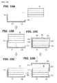
- FIG. 10 a description is given of a method for assembling the cell module 2 pertaining to the second embodiment according to the present invention.
- the cell units 30 is placed on the upper right of the first case 110 in the XZ plane (see Fig. 10A ). Then, the cell unit 30 is moved leftward in the X-direction without interfering the side surface 113 until the cell unit 30 contacts or abuts against the side surface 112 of the first case 110 (see FIG. 10B ). Then, by using the side surface 112 as a guide, the cell unit 30 is moved downward in the Z-direction until the cell unit 30 contacts the main surface 111 of the first case 110 ( FIG. 10C ).
- the second case 210 is placed on right above the cell unit 30 in the XZ plane, and is moved leftward in the X-direction without interfering the side member 213 until abutting against the side surface 212 of the second case 210 (see FIG. 10D ). Finally, by using the side surface 212 as a guide, the second case 210 is moved downward in the Z-direction until contacting the main surface 211 of the second case 210 (see FIG. 10E ).
- the battery module 2 pertaining to the second embodiment according to the present invention is assembled.
- the battery module 1 pertaining to the second embodiment according to the present invention includes a cell unit 30 comprising four unit cells 10 (10A ⁇ 10D), a pair of first case 110 and second case 210 to enclose so as to accommodate the cell unit 30.
- the first case 110 and the second case 210 are respectively provided with a main surface 111, 211 and a side surface 112, 212 bent at both ends of the main surface 111,211 and extending with different lengths each other in a direction away from the main surface 111, 211.
- the cell unit 30 may be accommodated in the first case 110.
- the second case 210 in X-direction relatively until abutting against the side surface 212 of the second case 210 and by moving the second case 210 in Z-direction relatively using the side surface 212 as a guide, the cell unit 30 may be covered by the second case 210.
- a battery module 2 may be provided in which the assembly is easy and the cell unit 30 may be prevented from being damaged at the time of assembly.
- the first case 110 and the second case 210 are respectively provided with a pair of side surfaces 112, 113; 212, 213, it is possible to suppress deformation at the time of falling.
- FIG. 11 is a schematic sectional view showing a battery pack 7 pertaining to a first modification.
- the battery pack 7 is provided with battery modules 3 (3A, 3B), each including a cell unit 30 (30A, 30B) including four unit cells 10 (10A to 10D), a pair of first case 120 (120A, 120B) and second case 220 (220A, 220B) for enclosing to accommodate the cell unit 30.
- the first case 120 includes a main surface 121 (121A, 121B) and a side surface 122 (122A, 122B) bend at one end of the main surface 121 and extending in a direction away from the main surface 121.
- the second case 220 includes a main surface 221 (221A, 221B) and a side surface 222 (222A, 22B) bent at one end of the main surface 221 and extending in a direction away from the main surface 221.
- the battery module 3 is laminated such that the side surface 122A of one battery module 3A is opposed to the side surface 222B of the other battery module 3B.
- the side surface 222B of the second case 220B of the other adjacent battery module 3B is arranged.
- the main surface 121A of the first case 120A of the one battery module 3A supports the side surface 222B of the second case 220B of the other battery module 3B. Therefore, the deformation of the second case 220B of the other battery modules 3B can be suppressed.
- FIG. 12 is a schematic sectional view showing a battery pack 8 pertaining to the second modification.
- the battery pack 8 pertaining to the second modification 2 includes battery modules 4 (4A, 4B), each including four unit cells 10 (10A to 10D) cell units 30 (30A, 30B), a pair of first case 130 (130A, 130B) and second case 230 (230A, 230B) for enclosing to accommodate the cell unit 30.
- the first case 130 is provided with a main surface 131 (131A, 131B) and a pair of side surfaces 132 (132A, 132B), 133 (133A, 133B) bent at both ends of the main surface 131 and extending with different lengths in a direction away from the main surface 131.
- the side surfaces 132, 232 are formed with the extension length longer than the side surfaces 133, 233.
- the battery module 4 is laminated such that the side surface 132A of one battery module 4A and the side surface 232A of the other battery module 4B are opposed to each other. Then, in extension in the X direction of the main surface 131A of the first case 130A of the one battery module 4A, the side surface 232B of the second case 230B of the other adjacent battery module 4B is arranged.
- the main surface 131A of the first case 130A of the one battery module 4A supports the side surface 232B of the second case 230B of the other battery module 4B. Therefore, the deformation of the second case 230B of the other battery modules 4B can be suppressed.
- FIG. 13 is a schematic cross-sectional view showing a battery module 2 pertaining to a third modification.
- the first case 100, 110 and the second case 200, 210 are of the same shape. However, as shown in FIG. 13 , the first case 140 and the second case may have a different shape.
- FIG. 14 is a schematic cross-sectional view showing a battery module 3 pertaining to a fourth modification.
- the first case 100, 110, and the second case 200, 210 are configured to be assembled in a "laid-down" state.
- the first case 170 and second case 270 may be configured to be assembled in an "upright or standing" state.
Landscapes
- Chemical & Material Sciences (AREA)
- Chemical Kinetics & Catalysis (AREA)
- Electrochemistry (AREA)
- General Chemical & Material Sciences (AREA)
- Battery Mounting, Suspending (AREA)
Abstract
Description
- The present invention relates to a battery module and a battery pack.
- In recent years, in the field of automobile industry and advanced electronic industry, the demand for secondary batteries such as automobile batteries and electronic devices is increasing. In these secondary batteries, an exterior or outer member made of a flexibly deformable laminate sheet seals a unit cell which is a battery element. Furthermore, a battery module is structured by enclosing a cell unit including a laminate of several such unit cells stacked on one another by upper and lower cases. Moreover, by connecting multiple battery modules configured in this way in series or in parallel, a battery pack is formed, which corresponds to a desired current, voltage, or capacity (for example, see Patent Document 1).
- Patent Document 1:
JP 2003-203615 - In the secondary battery described in Patent Document 1, however, since the height of a pair of side surfaces of the upper and lower covers are the same, when accommodating the cell unit in the lower cover at the time of assembly, or when covering the cell unit with a top cover, it is necessary to adjust the battery module, the upper cover, or the lower cover to find a position for proper fitting. Therefore, it takes a long time for assembly. Also, there is a concern that the cell unit is damaged due to interference to of the cell unit with the side surface.
- The present invention has been made to solve the above problem, and an object thereof is to provide a battery module and a battery pack which may be easily assembled and may be prevented from being damaged when assembling.
- In order to achieve the above object, a battery module according to the present invention comprises a cell unit having at least one unit cell, and first and second cases, which are paired to enclose and house the cell unit. Each of the first and second cases has a main surface and either one side surface bent at one end of and extending in a direction away from the main surface or a pair of side surfaces bent at both ends of and extending in a direction away from the main surface with different extension lengths from each other.
- In the battery module constructed as above, the cell unit is relatively moved to the first case until abutting against a side surface bent at and extending from one end of the main surface or a side surface with longer extension length of the pair of side surfaces, in a direction perpendicular to the surface(s). Then, the cell unit is relatively moved to the first case in a direction of extension of the side surface by using the side surface as a guide until abutting against the side surface bent at and extending from one end of the main surface or the side surface with longer extension length of the pair of side surfaces. Then, by moving the cell unit relatively to the second case in a direction of extension of the side surface using the side surface as a guide, the cell unit may be covered by the second case. Therefore, it is possible to provide a battery module which may be easily assembled and is capable of being prevented from damage during assembly process.
-
-
FIG. 1 is a perspective view showing a battery module pertaining to a first embodiment according to the present invention; -
FIG. 2 is a schematic sectional view taken along line 2-2 inFIG. 2 ; -
FIG. 3 is a perspective view of a cell unit of the battery module; -
FIG. 4 is an exploded perspective view showing the internal structure of the unit cell of the battery module: -
FIG. 5 is an exploded perspective view showing the internal structure of the cell unit of the battery module; -
FIG. 6 is a diagram showing an electrical connection of a plurality of unit cells constituting the battery module; -
FIG. 7 is a sectional view taken along line 7-7 ofFIG. 1 ; -
FIG. 8 is a schematic cross-sectional view illustrating a method of assembling a battery module in the first embodiment: -
FIG. 9 is a schematic sectional view showing a battery module pertaining to a second embodiment according to the present invention; -
FIG. 10 is a schematic cross-sectional view illustrating a method of assembling a battery module in the second embodiment; -
FIG. 11 is a schematic sectional view showing a battery pack pertaining to a first modification; -
FIG. 12 is a schematic sectional view showing a battery pack pertaining to a second modification; -
FIG. 13 is a schematic sectional view showing a battery module pertaining to a third modification; and -
FIG. 14 is a schematic sectional view showing a battery module pertaining to a fourth modification 4. - Below, with reference to the accompanying drawings, a description will be given of a first embodiment according to the present invention. The same element is attached with the same reference numeral in the description of the drawings, and duplicate description will be omitted. Dimensional ratios of the drawings are exaggerated for convenience of explanation and may be different from the actual ratio. First, a description is given of the configuration of a battery module.
-
FIG. 1 is a perspective view of a battery module 1 pertaining to a first embodiment of the present invention.FIG. 2 is a schematic sectional view taken along line 2-2 ofFIG. 1 . InFIG. 2 , for simplicity of description, acell unit 30 is described by a block body.FIG. 3 is a perspective view of acell unit 30 of the battery module 1. Further, the schematic sectional views shown inFIGS. 8 to 16 below, are those similar toFIG. 2 taken along line 2-2 ofFIG. 1 . - A battery module 1 pertaining to the first embodiment according to the present invention is generally shown in
FIGS. 1-3 , and is provided with acell unit 30 with four cells 10 (10A to 10D), and a first andsecond cases cell unit 30. Each of the first andsecond cases main surface side surface 102, 103 bent at one end of themain surface main surface - The battery module 1 includes a
cell unit 30 having four unit cells 10 (10A ∼ 10D), a pair of the first andsecond cases cell unit 30 so as to enclose the cell unit. The battery module 1 is further provided with, in themain surface second cases hole 26 extending in an extension direction Z of theside surfaces fastening mechanism 70 which is inserted into a second throughhole 41 provided in the extension direction Z in aspacer 40 described below. Thefastening mechanism 70 in intended to fasten thefirst case 100, thecell unit 30, and thesecond case 200 together. - As shown in
FIG. 3 , thecell unit 30 includes astacked laminate 33 with four unit cells 10 (a0A to 10D) stacked on one another and electrically connected to each other, anexternal output terminal voltage detection terminal 37. Note that thelaminate 33 is configured by four unit cells 10 (10A to 10D). However, it is sufficient that at least one unit cell is provided. Theexternal output terminal positive electrode terminal 31 and an external outputnegative electrode terminal 32. -
FIG. 4 is an exploded perspective view showing the internal structure of theunit cell 10 of the battery module 1. - As shown in
FIG. 4 , the unit cell is for example a lithium ion secondary battery in which alaminate electrode body 50 is accommodated together with an electrolyte in anouter member 11 arranged on both sides of thelaminate electrode body 50. Theunit cell 10 has apositive electrode tab 14 and anegative electrode tab 15 derived from theouter member 11 to the outside. - The laminated
electrode body 50 is an electrode group formed by laminating or stacking alternately apositive electrode 51, aseparator 53, and anegative electrode 52. Thepositive electrode 51 includes a positive electrode active material layer composed of a transition metal complex oxide, for example, LiMn2O4.. Thenegative electrode 52 includes a negative electrode active material layer composed of a carbon and lithium-transition metal complex oxide. Theseparator 53 is formed, for example, from porous PE (polyethylene) having air permeability that can penetrate the electrolyte. - The outer or
package member 11 is formed, from the viewpoint of weight reduction and thermal conductivity, of a sheet member such as a polymer-metal composite laminate film in which a metal such as aluminum, stainless steel, nickel, copper, etc. (including alloys) is coated with an insulator such as a polypropylene film. Theouter member 11 has amain portion 12 covering thelaminated electrode body 50 and aperiphery portion 13 extending to the periphery of thebody portion 12 with a part or theentire periphery portion 13 joined by hot-melt or heat fusion. - The
positive electrode tab 14 and thenegative electrode tab 15 are intended to serve a member for drawing current from the stackedelectrode body 50 and extended to one side of theunit cell 10. -
FIG. 5 is an exploded perspective view showing the internal structure of thecell unit 30 of the battery module 1. - As shown in
FIG. 5 , thespacer 40, has a second throughhole 41 at both ends in the longitudinal direction X. The second throughhole 41 is aligned with the first throughhole 26 of thefirst case 100 andsecond case 200, and is used for having asleeve 71 inserted. For thespacer 40, use is made of an electrically insulating resin material. - In addition, the
positive electrode tab 14A of thefirst unit cell 10A and the positive electrode tab 14B of thesecond unit cell 10B are joined by ultrasonic welding or the like to abus bar 60 which is connected to the external outputpositive terminal 31. On the other hand, thenegative electrode tab 15A of thefirst unit cell 10A and thenegative electrode tab 15B of thesecond unit cell 10B are connected, jointly with thepositive electrode tabs 14C, 14D of the third andfourth unit cells bus bar 61 by ultrasonic welding or the like, which in turn is electrically connected to thevoltage detection terminal 37. Further, thenegative electrode tab 15C of thethird unit cell 10C and thenegative electrode tab 15D of thefourth unit cell 10D are connected to abus bar 62 by ultrasonic welding or the like, which is electrically connected to the external outputnegative terminal 32. - As described above, each of the
electrode tabs 14A to 14D, 15A to 15D of theunit cells 10A to 10D are connected via thebus bar positive electrode terminal 31, the external outputnegative electrode terminal 32, and thevoltage detection terminal 37, respectively. Thus, as shown inFIG. 6 , theseunit cells 10A to 10D are configured to form a two parallel two series connection. - The
voltage detection terminal 37 is provided to detect the voltage of thebattery cell 10A to 10D constituting the battery module 1. Specifically, by using the external outputpositive terminal 31 and thevoltage detection terminal 37 and measuring the voltage between these terminals, the voltage of thefirst battery cell 10A and that of thesecond battery cell 10B can be detected. Also, the voltage of thethird unit cell 10C and that of thefourth unit cell 10D can be detected by using the external outputnegative terminal 32 and thevoltage detection terminal 37 and measuring the voltage between these terminals. - As shown in
FIG. 2 , thefirst case 100 and thesecond case 200 are respectively provided with amain surface side surface main surface first case 100 andsecond case 200 are of the same shape. Thefirst case 100 andsecond case 200 are arranged to be staggered and are opposed to each other at twomating portions main surface holes 26 penetrating in the extension direction Z. The material of thefirst case 100 andsecond case 200 is preferably a material having a higher melting point than the heat flow temperature (700 to 1000 °C above)ejected when the battery module 1 is damaged, such as steel and the like. -
FIG. 7 is a sectional view taken along line 7-7 ofFIG 1 . As shown inFIG. 7 , the fastening mechanism orfastener 70 is inserted into the first throughhole 26 and the second throughhole 41 for fastening thefirst case 100, thecell unit 30 and thesecond case 200. Thefastener 70 includes asleeve 71 which is inserted into the first throughhole 26 and the second throughhole 41, a press-fit collar 72 for fastening thefirst case 100, thecell unit 30, and thesecond case 200 by being pressed from above and below thesleeve 71. Note that, in the present embodiment, thefastener 70 includes thesleeve 71 and the press-fit collar 72. However, the structure is not limited thereto as long as thefirst case 100, thecell unit 30, and thesecond case 200 can be fastened. - Referring now to
FIG. 8 , a description is given of a method for assembling the battery module 1 in the first embodiment according to the present invention. - First, the
cell units 30 is placed on the upper right of thefirst case 100 in the XZ plane (seeFig. 8 A) . Then, thecell unit 30 is moved leftward in the X-direction until thecell unit 30 contacts or abuts against theside surface 102 of the first case 100 (seeFIG. 8B ). Then, by using theside surface 102 as a guide, thecell unit 30 is moved downward in the Z-direction until thecell unit 30 contacts themain surface 101 of the first case 100 (FIG. 8C ). Then, thesecond case 200 is placed on right above thecell unit 30 in the XZ plane, and is moved leftward in the X-direction until abutting against theside surface 202 of the second case 200 (seeFIG. 8D ). Finally, by using theside surface 202 as a guide, thesecond case 200 is moved downward in the Z-direction until contacting themain surface 201 of the second case 200 (seeFIG. 8E ). - Due to the above steps, the battery module 1 pertaining to the first embodiment according to the present invention is assembled. Note that, in the present embodiment, the
cell unit 30 is moved toward thefirst case 100, and the second case is moved toward thecell unit 30 to assemble the battery module 1. However, the battery module 1 may be assembled by moving thefirst case 100 toward thecell unit 30, and by moving thecell unit 30 and thefirst case 100 toward thesecond case 200, as well. - As described above, the battery module 1 pertaining to the first embodiment according to the present invention, includes a
cell unit 30 comprising four unit cells 10 (10A to 10D), a pair offirst case 100 andsecond case 200 to enclose and accommodate thecell unit 30. Thefirst case 100 and thesecond case 200 are respectively provided with amain surface side surface 102, 2012 bent at one end of themain surface main surface cell unit 30 in a X-direction relative to thefirst case 100 until abutting against theside surface 102 thereof, and by moving thecell unit 30 in Z-direction relatively using theside surface 102 as a guide, thecell unit 30 may be accommodated in thefirst case 100. Further, by moving thesecond case 200 in X-direction relatively until abutting against theside surface 202 of thesecond case 200, and by moving thesecond case 200 in Z-direction relatively using theside surface 202 as a guide, thecell unit 30 may be covered by thesecond case 200. Thus, such a battery module 1 may be provided in which the assembly is easy and thecell unit 30 may be prevented from being damaged at the time of assembly. Further, when forming thefirst case 100 andsecond case 200 by press molding, it is possible to reduce the number of forming to thereby shorten the manufacturing time. - In addition, the
first case 100 andsecond case 200 are of the same shape. Therefore, it is possible to reduce the number of components while reducing the cost. - Also, each of the
main surfaces first case 100 andsecond case 200 is formed with the first throughhole 26 in the Z direction. Thecell unit 30 is provided with aspacer 40 which is fixed to the end of theunit cell 10 and the second throughhole 41 in the Z direction. Further, the battery module 1 also includes a fastening mechanism orfastener 70 which is inserted into the first throughhole 26 and the second throughhole 41 to thereby fasten thefirst case 100, thecell unit 30, and thesecond case 200. Therefore, by thefastener 70, it is possible to easily position thefirst casing 100,cell unit 30 and thesecond case 200. - Now, a description is given of a second embodiment according to the present invention. Parts common to the first embodiment will be omitted, and a description is given only of the portion featuring the second embodiment.
-
FIG. 9 is a schematic cross-sectional view showing abattery module 2 pertaining to a second embodiment according to the present invention. - As shown in
FIG. 9 , acell module 2 pertaining to a second embodiment according to the present invention is generally provided with a cell unit having four unit cells 10 (10A to 10D), and a pair of a first andsecond cases cell unit 30. Thefirst case 110 and thesecond case 210 are respectively provided with amain surface main surface main surface - The
first case 110 includes amain surface 111 and a pair of side surfaces 112, 113 which are bent on both ends of themain surface 11 and extending with different lengths in a direction away from themain surface 111. Theside surface 112 is formed longer in the extension length than theside surface 113. - The
second case 210 includes amain surface 211 and a pair of side surfaces 212, 213 which are bent at both ends of themain surface 211 and extending with different lengths from each other and in a direction away from themain surface 211. The extension length of theside surface 212 is longer than theside surface 213. - The
first case 110 andsecond case 210 are arranged to be staggered, and opposed to each other with a gap at twomating portions - Referring now to
FIG. 10 , a description is given of a method for assembling thecell module 2 pertaining to the second embodiment according to the present invention. - First, the
cell units 30 is placed on the upper right of thefirst case 110 in the XZ plane (seeFig. 10A ). Then, thecell unit 30 is moved leftward in the X-direction without interfering theside surface 113 until thecell unit 30 contacts or abuts against theside surface 112 of the first case 110 (seeFIG. 10B ). Then, by using theside surface 112 as a guide, thecell unit 30 is moved downward in the Z-direction until thecell unit 30 contacts themain surface 111 of the first case 110 (FIG. 10C ). Then, thesecond case 210 is placed on right above thecell unit 30 in the XZ plane, and is moved leftward in the X-direction without interfering theside member 213 until abutting against theside surface 212 of the second case 210 (seeFIG. 10D ). Finally, by using theside surface 212 as a guide, thesecond case 210 is moved downward in the Z-direction until contacting themain surface 211 of the second case 210 (seeFIG. 10E ). - By the steps described above, the
battery module 2 pertaining to the second embodiment according to the present invention is assembled. - As described above, the battery module 1 pertaining to the second embodiment according to the present invention, includes a
cell unit 30 comprising four unit cells 10 (10A ∼ 10D), a pair offirst case 110 andsecond case 210 to enclose so as to accommodate thecell unit 30. Thefirst case 110 and thesecond case 210 are respectively provided with amain surface side surface main surface cell unit 30 in a X-direction relative to thefirst case 110 until abutting against theside surface 112 thereof, and by moving thecell unit 30 in Z-direction relatively using theside surface 112 as a guide, thecell unit 30 may be accommodated in thefirst case 110. Further, by moving thesecond case 210 in X-direction relatively until abutting against theside surface 212 of thesecond case 210, and by moving thesecond case 210 in Z-direction relatively using theside surface 212 as a guide, thecell unit 30 may be covered by thesecond case 210. Thus, such abattery module 2 may be provided in which the assembly is easy and thecell unit 30 may be prevented from being damaged at the time of assembly. Further, since thefirst case 110 and thesecond case 210 are respectively provided with a pair of side surfaces 112, 113; 212, 213, it is possible to suppress deformation at the time of falling. - Below, a modification of the above embodiment is described.
-
FIG. 11 is a schematic sectional view showing abattery pack 7 pertaining to a first modification. As shown inFIG. 11 , thebattery pack 7 is provided with battery modules 3 (3A, 3B), each including a cell unit 30 (30A, 30B) including four unit cells 10 (10A to 10D), a pair of first case 120 (120A, 120B) and second case 220 (220A, 220B) for enclosing to accommodate thecell unit 30. The first case 120 includes a main surface 121 (121A, 121B) and a side surface 122 (122A, 122B) bend at one end of the main surface 121 and extending in a direction away from the main surface 121. Further, the second case 220 includes a main surface 221 (221A, 221B) and a side surface 222 (222A, 22B) bent at one end of the main surface 221 and extending in a direction away from the main surface 221. Thebattery module 3 is laminated such that theside surface 122A of onebattery module 3A is opposed to theside surface 222B of theother battery module 3B. In addition, Then, in extension in the X direction of themain surface 121A of thefirst case 120A of the onebattery module 3A, theside surface 222B of thesecond case 220B of the otheradjacent battery module 3B is arranged. According to this configuration, due to the heat flow that occurs at failure in theother battery modules 3B, when theside surface 222B of thesecond case 220B of theother battery modules 3B presses the onebattery module 3A rightward in the X-direction, themain surface 121A of thefirst case 120A of the onebattery module 3A supports theside surface 222B of thesecond case 220B of theother battery module 3B. Therefore, the deformation of thesecond case 220B of theother battery modules 3B can be suppressed. -
FIG. 12 is a schematic sectional view showing a battery pack 8 pertaining to the second modification. As shown inFIG. 12 , the battery pack 8 pertaining to thesecond modification 2 includes battery modules 4 (4A, 4B), each including four unit cells 10 (10A to 10D) cell units 30 (30A, 30B), a pair of first case 130 (130A, 130B) and second case 230 (230A, 230B) for enclosing to accommodate thecell unit 30. The first case 130 is provided with a main surface 131 (131A, 131B) and a pair of side surfaces 132 (132A, 132B), 133 (133A, 133B) bent at both ends of the main surface 131 and extending with different lengths in a direction away from the main surface 131. The side surfaces 132, 232 are formed with the extension length longer than the side surfaces 133, 233. The battery module 4 is laminated such that theside surface 132A of onebattery module 4A and the side surface 232A of theother battery module 4B are opposed to each other. Then, in extension in the X direction of themain surface 131A of thefirst case 130A of the onebattery module 4A, theside surface 232B of thesecond case 230B of the otheradjacent battery module 4B is arranged. According to this configuration, due to the heat flow that occurs at failure in theother battery modules 4B, when theside surface 232B of thesecond case 230B of theother battery modules 4B presses the onebattery module 4A rightward in the X-direction, themain surface 131A of thefirst case 130A of the onebattery module 4A supports theside surface 232B of thesecond case 230B of theother battery module 4B. Therefore, the deformation of thesecond case 230B of theother battery modules 4B can be suppressed. -
FIG. 13 is a schematic cross-sectional view showing abattery module 2 pertaining to a third modification. In the first and second embodiments, thefirst case second case FIG. 13 , thefirst case 140 and the second case may have a different shape. -
FIG. 14 is a schematic cross-sectional view showing abattery module 3 pertaining to a fourth modification. In the first and second embodiments, thefirst case second case FIG. 14 , thefirst case 170 andsecond case 270 may be configured to be assembled in an "upright or standing" state. -
- 1, 2, 2', 3, 3', 4
- battery modules
- 7, 8
- battery pack
- 10
- unit cell
- 26
- first through hole
- 30
- cell unit
- 40
- spacer
- 41
- second through hole
- 70
- fastening mechanism, fastener
- 100, 110, 120, 130, 140, 170
- first case
- 200, 210, 220, 230, 240, 270
- second case
- 101, 111, 121, 131, 201, 211, 221, 231
- main surface
- 102, 112, 113, 122, 132, 133, 202, 212, 213, 222, 232, 233
- side surface
- 150, 160
- mating portion
Claims (4)
- A battery module, comprising:a cell unit having at least one unit cell, anda pair of first and second cases to enclose and accommodate the cell unit, each of the first and second cases having a main surface and either a side surface bent at one end of and extending in a direction away from the main surface or a pair of side surfaces bent at both ends of the main surface and extending in a direction away from the main surface with different extension lengths from each other.
- The battery module as claimed in claim 1, wherein the first case and the second case are of the same shape.
- The battery module as claimed in either claim 1 or 2, wherein each of the main surfaces of the first case and the second case is formed with a first through hole in the extension direction of the side surface, the battery module further comprising:a spacer provided with the cell unit which is fixed to the end of the unit cell and a second through hole in the extension direction of the side surface in the extension direction, anda fastener inserted into the first through hole and the second through hole to thereby fasten the first case, the cell unit, and the second case.
- A battery pack including the battery module described in any one of claims 1 to 3, wherein the side surface of one battery module and the side surface of the other battery module are disposed to be adjacent each other, and, in extension of the main surface of the first case of the one battery module in the stacking direction of the battery module, the side surface bent at one end of the main surface and extending or the side surface with a longer extension length of the second case in which the side surfaces are bent at both ends of the main surface and extending is disposed.
Applications Claiming Priority (2)
| Application Number | Priority Date | Filing Date | Title |
|---|---|---|---|
| JP2012285107 | 2012-12-27 | ||
| PCT/JP2013/083131 WO2014103709A1 (en) | 2012-12-27 | 2013-12-10 | Battery module and battery pack |
Publications (3)
| Publication Number | Publication Date |
|---|---|
| EP2940757A1 true EP2940757A1 (en) | 2015-11-04 |
| EP2940757A4 EP2940757A4 (en) | 2015-12-30 |
| EP2940757B1 EP2940757B1 (en) | 2018-03-21 |
Family
ID=51020798
Family Applications (1)
| Application Number | Title | Priority Date | Filing Date |
|---|---|---|---|
| EP13867690.3A Active EP2940757B1 (en) | 2012-12-27 | 2013-12-10 | Battery module and battery pack |
Country Status (6)
| Country | Link |
|---|---|
| US (1) | US9437845B2 (en) |
| EP (1) | EP2940757B1 (en) |
| JP (1) | JP6036850B2 (en) |
| KR (1) | KR101652653B1 (en) |
| CN (1) | CN104919618B (en) |
| WO (1) | WO2014103709A1 (en) |
Families Citing this family (7)
| Publication number | Priority date | Publication date | Assignee | Title |
|---|---|---|---|---|
| CN107632049B (en) * | 2016-07-19 | 2021-07-13 | 松下知识产权经营株式会社 | Detection Systems |
| JPWO2018143463A1 (en) * | 2017-02-06 | 2019-06-27 | 日立オートモティブシステムズ株式会社 | Battery pack |
| KR102164632B1 (en) | 2017-07-31 | 2020-10-12 | 주식회사 엘지화학 | Battery module, battery pack and energy storage system comprising the same |
| CA3092216A1 (en) * | 2019-09-10 | 2021-03-10 | Proterra Inc. | Battery system of an electric vehicle |
| CN115136398B (en) * | 2020-09-22 | 2025-07-04 | 株式会社Lg新能源 | Battery module and manufacturing method thereof, and battery pack including the battery module |
| JP7361069B2 (en) * | 2021-05-28 | 2023-10-13 | プライムプラネットエナジー&ソリューションズ株式会社 | An assembled battery spacer and an assembled battery equipped with the assembled battery spacer |
| KR20260005574A (en) * | 2024-07-03 | 2026-01-12 | 주식회사 엘지에너지솔루션 | Battery module, Battery pack and vehicle including the same |
Family Cites Families (12)
| Publication number | Priority date | Publication date | Assignee | Title |
|---|---|---|---|---|
| CA1029437A (en) * | 1973-12-14 | 1978-04-11 | P.R. Mallory And Co. Inc. | Disposable battery cartridge |
| JPH0592420A (en) | 1991-10-02 | 1993-04-16 | Hitachi Metals Ltd | Processing method for rare earth magnet |
| JPH05121056A (en) * | 1991-10-28 | 1993-05-18 | Yuasa Corp | Thin type battery |
| JP2003059471A (en) * | 2001-08-20 | 2003-02-28 | Sony Corp | Battery housing |
| JP3937839B2 (en) | 2001-12-28 | 2007-06-27 | 日本電気株式会社 | module |
| JP4894140B2 (en) | 2004-11-29 | 2012-03-14 | 日産自動車株式会社 | Assembled battery |
| JP4251204B2 (en) * | 2006-08-31 | 2009-04-08 | 日産自動車株式会社 | Battery module |
| KR101264432B1 (en) * | 2006-09-18 | 2013-05-14 | 삼성에스디아이 주식회사 | Battery Pack Including Out-Case With A Step |
| JP4775436B2 (en) * | 2008-02-29 | 2011-09-21 | 日産自動車株式会社 | Battery module and battery module manufacturing method |
| JP5657273B2 (en) * | 2009-05-15 | 2015-01-21 | 日産自動車株式会社 | Multilayer battery, battery module, and method of manufacturing multilayer battery |
| EP2355201B1 (en) * | 2010-01-29 | 2018-12-26 | Renault S.A.S. | Battery pack for an electric powertrain vehicle |
| JP5605252B2 (en) * | 2011-02-08 | 2014-10-15 | トヨタ自動車株式会社 | Power storage device |
-
2013
- 2013-12-10 CN CN201380068325.7A patent/CN104919618B/en active Active
- 2013-12-10 JP JP2014554300A patent/JP6036850B2/en active Active
- 2013-12-10 WO PCT/JP2013/083131 patent/WO2014103709A1/en not_active Ceased
- 2013-12-10 EP EP13867690.3A patent/EP2940757B1/en active Active
- 2013-12-10 KR KR1020157012957A patent/KR101652653B1/en active Active
- 2013-12-10 US US14/653,101 patent/US9437845B2/en active Active
Also Published As
| Publication number | Publication date |
|---|---|
| JP6036850B2 (en) | 2016-12-07 |
| JPWO2014103709A1 (en) | 2017-01-12 |
| US20150372260A1 (en) | 2015-12-24 |
| WO2014103709A1 (en) | 2014-07-03 |
| CN104919618B (en) | 2017-09-26 |
| EP2940757A4 (en) | 2015-12-30 |
| EP2940757B1 (en) | 2018-03-21 |
| CN104919618A (en) | 2015-09-16 |
| US9437845B2 (en) | 2016-09-06 |
| KR20150080517A (en) | 2015-07-09 |
| KR101652653B1 (en) | 2016-08-30 |
Similar Documents
| Publication | Publication Date | Title |
|---|---|---|
| EP3671902B1 (en) | Battery module having bus bar assembly | |
| EP2940757B1 (en) | Battery module and battery pack | |
| EP3512001B1 (en) | Secondary battery and vehicle | |
| US8771863B2 (en) | Battery module and manufacturing method of battery module | |
| EP2535962B1 (en) | Battery module having enhanced welding reliability and medium or large battery pack including same | |
| US9515302B2 (en) | Rechargeable battery pack | |
| US9397320B2 (en) | Battery pack | |
| EP2220703B1 (en) | Secondary battery pack and ptc element having excellent production process property | |
| CN103367668B (en) | Battery | |
| EP4053989B1 (en) | Battery module having busbar, battery pack and vehicle | |
| US10468647B2 (en) | Battery pack | |
| US20140205888A1 (en) | Battery module | |
| JP6594455B2 (en) | Battery module with wire fixing rib | |
| JP2011243561A (en) | Battery pack | |
| EP2905824B1 (en) | Battery pack | |
| EP3806180B1 (en) | Battery module | |
| US9224989B2 (en) | Rechargeable battery and module thereof | |
| KR20150137841A (en) | Unit battery modue, Battery module and Battery pack And Method for manufacturing the same | |
| US10320035B2 (en) | Battery pack | |
| KR101502899B1 (en) | Battery Pack | |
| KR102517098B1 (en) | Battery module |
Legal Events
| Date | Code | Title | Description |
|---|---|---|---|
| PUAI | Public reference made under article 153(3) epc to a published international application that has entered the european phase |
Free format text: ORIGINAL CODE: 0009012 |
|
| 17P | Request for examination filed |
Effective date: 20150511 |
|
| AK | Designated contracting states |
Kind code of ref document: A1 Designated state(s): AL AT BE BG CH CY CZ DE DK EE ES FI FR GB GR HR HU IE IS IT LI LT LU LV MC MK MT NL NO PL PT RO RS SE SI SK SM TR |
|
| AX | Request for extension of the european patent |
Extension state: BA ME |
|
| A4 | Supplementary search report drawn up and despatched |
Effective date: 20151201 |
|
| RIC1 | Information provided on ipc code assigned before grant |
Ipc: H01M 2/10 20060101AFI20151125BHEP Ipc: H01M 2/02 20060101ALI20151125BHEP |
|
| DAX | Request for extension of the european patent (deleted) | ||
| 17Q | First examination report despatched |
Effective date: 20160923 |
|
| GRAP | Despatch of communication of intention to grant a patent |
Free format text: ORIGINAL CODE: EPIDOSNIGR1 |
|
| INTG | Intention to grant announced |
Effective date: 20171107 |
|
| GRAS | Grant fee paid |
Free format text: ORIGINAL CODE: EPIDOSNIGR3 |
|
| GRAA | (expected) grant |
Free format text: ORIGINAL CODE: 0009210 |
|
| AK | Designated contracting states |
Kind code of ref document: B1 Designated state(s): AL AT BE BG CH CY CZ DE DK EE ES FI FR GB GR HR HU IE IS IT LI LT LU LV MC MK MT NL NO PL PT RO RS SE SI SK SM TR |
|
| REG | Reference to a national code |
Ref country code: GB Ref legal event code: FG4D |
|
| REG | Reference to a national code |
Ref country code: CH Ref legal event code: EP |
|
| REG | Reference to a national code |
Ref country code: AT Ref legal event code: REF Ref document number: 981984 Country of ref document: AT Kind code of ref document: T Effective date: 20180415 |
|
| REG | Reference to a national code |
Ref country code: IE Ref legal event code: FG4D |
|
| REG | Reference to a national code |
Ref country code: DE Ref legal event code: R096 Ref document number: 602013034900 Country of ref document: DE |
|
| REG | Reference to a national code |
Ref country code: NL Ref legal event code: MP Effective date: 20180321 |
|
| PG25 | Lapsed in a contracting state [announced via postgrant information from national office to epo] |
Ref country code: HR Free format text: LAPSE BECAUSE OF FAILURE TO SUBMIT A TRANSLATION OF THE DESCRIPTION OR TO PAY THE FEE WITHIN THE PRESCRIBED TIME-LIMIT Effective date: 20180321 Ref country code: NO Free format text: LAPSE BECAUSE OF FAILURE TO SUBMIT A TRANSLATION OF THE DESCRIPTION OR TO PAY THE FEE WITHIN THE PRESCRIBED TIME-LIMIT Effective date: 20180621 Ref country code: LT Free format text: LAPSE BECAUSE OF FAILURE TO SUBMIT A TRANSLATION OF THE DESCRIPTION OR TO PAY THE FEE WITHIN THE PRESCRIBED TIME-LIMIT Effective date: 20180321 Ref country code: FI Free format text: LAPSE BECAUSE OF FAILURE TO SUBMIT A TRANSLATION OF THE DESCRIPTION OR TO PAY THE FEE WITHIN THE PRESCRIBED TIME-LIMIT Effective date: 20180321 Ref country code: CY Free format text: LAPSE BECAUSE OF FAILURE TO SUBMIT A TRANSLATION OF THE DESCRIPTION OR TO PAY THE FEE WITHIN THE PRESCRIBED TIME-LIMIT Effective date: 20180321 |
|
| REG | Reference to a national code |
Ref country code: LT Ref legal event code: MG4D |
|
| REG | Reference to a national code |
Ref country code: AT Ref legal event code: MK05 Ref document number: 981984 Country of ref document: AT Kind code of ref document: T Effective date: 20180321 |
|
| PG25 | Lapsed in a contracting state [announced via postgrant information from national office to epo] |
Ref country code: GR Free format text: LAPSE BECAUSE OF FAILURE TO SUBMIT A TRANSLATION OF THE DESCRIPTION OR TO PAY THE FEE WITHIN THE PRESCRIBED TIME-LIMIT Effective date: 20180622 Ref country code: SE Free format text: LAPSE BECAUSE OF FAILURE TO SUBMIT A TRANSLATION OF THE DESCRIPTION OR TO PAY THE FEE WITHIN THE PRESCRIBED TIME-LIMIT Effective date: 20180321 Ref country code: LV Free format text: LAPSE BECAUSE OF FAILURE TO SUBMIT A TRANSLATION OF THE DESCRIPTION OR TO PAY THE FEE WITHIN THE PRESCRIBED TIME-LIMIT Effective date: 20180321 Ref country code: BG Free format text: LAPSE BECAUSE OF FAILURE TO SUBMIT A TRANSLATION OF THE DESCRIPTION OR TO PAY THE FEE WITHIN THE PRESCRIBED TIME-LIMIT Effective date: 20180621 Ref country code: RS Free format text: LAPSE BECAUSE OF FAILURE TO SUBMIT A TRANSLATION OF THE DESCRIPTION OR TO PAY THE FEE WITHIN THE PRESCRIBED TIME-LIMIT Effective date: 20180321 |
|
| PG25 | Lapsed in a contracting state [announced via postgrant information from national office to epo] |
Ref country code: IT Free format text: LAPSE BECAUSE OF FAILURE TO SUBMIT A TRANSLATION OF THE DESCRIPTION OR TO PAY THE FEE WITHIN THE PRESCRIBED TIME-LIMIT Effective date: 20180321 Ref country code: RO Free format text: LAPSE BECAUSE OF FAILURE TO SUBMIT A TRANSLATION OF THE DESCRIPTION OR TO PAY THE FEE WITHIN THE PRESCRIBED TIME-LIMIT Effective date: 20180321 Ref country code: AL Free format text: LAPSE BECAUSE OF FAILURE TO SUBMIT A TRANSLATION OF THE DESCRIPTION OR TO PAY THE FEE WITHIN THE PRESCRIBED TIME-LIMIT Effective date: 20180321 Ref country code: EE Free format text: LAPSE BECAUSE OF FAILURE TO SUBMIT A TRANSLATION OF THE DESCRIPTION OR TO PAY THE FEE WITHIN THE PRESCRIBED TIME-LIMIT Effective date: 20180321 Ref country code: NL Free format text: LAPSE BECAUSE OF FAILURE TO SUBMIT A TRANSLATION OF THE DESCRIPTION OR TO PAY THE FEE WITHIN THE PRESCRIBED TIME-LIMIT Effective date: 20180321 Ref country code: PL Free format text: LAPSE BECAUSE OF FAILURE TO SUBMIT A TRANSLATION OF THE DESCRIPTION OR TO PAY THE FEE WITHIN THE PRESCRIBED TIME-LIMIT Effective date: 20180321 Ref country code: ES Free format text: LAPSE BECAUSE OF FAILURE TO SUBMIT A TRANSLATION OF THE DESCRIPTION OR TO PAY THE FEE WITHIN THE PRESCRIBED TIME-LIMIT Effective date: 20180321 |
|
| PG25 | Lapsed in a contracting state [announced via postgrant information from national office to epo] |
Ref country code: AT Free format text: LAPSE BECAUSE OF FAILURE TO SUBMIT A TRANSLATION OF THE DESCRIPTION OR TO PAY THE FEE WITHIN THE PRESCRIBED TIME-LIMIT Effective date: 20180321 Ref country code: CZ Free format text: LAPSE BECAUSE OF FAILURE TO SUBMIT A TRANSLATION OF THE DESCRIPTION OR TO PAY THE FEE WITHIN THE PRESCRIBED TIME-LIMIT Effective date: 20180321 Ref country code: SK Free format text: LAPSE BECAUSE OF FAILURE TO SUBMIT A TRANSLATION OF THE DESCRIPTION OR TO PAY THE FEE WITHIN THE PRESCRIBED TIME-LIMIT Effective date: 20180321 Ref country code: SM Free format text: LAPSE BECAUSE OF FAILURE TO SUBMIT A TRANSLATION OF THE DESCRIPTION OR TO PAY THE FEE WITHIN THE PRESCRIBED TIME-LIMIT Effective date: 20180321 |
|
| PG25 | Lapsed in a contracting state [announced via postgrant information from national office to epo] |
Ref country code: PT Free format text: LAPSE BECAUSE OF FAILURE TO SUBMIT A TRANSLATION OF THE DESCRIPTION OR TO PAY THE FEE WITHIN THE PRESCRIBED TIME-LIMIT Effective date: 20180723 |
|
| REG | Reference to a national code |
Ref country code: DE Ref legal event code: R097 Ref document number: 602013034900 Country of ref document: DE |
|
| PLBE | No opposition filed within time limit |
Free format text: ORIGINAL CODE: 0009261 |
|
| STAA | Information on the status of an ep patent application or granted ep patent |
Free format text: STATUS: NO OPPOSITION FILED WITHIN TIME LIMIT |
|
| PG25 | Lapsed in a contracting state [announced via postgrant information from national office to epo] |
Ref country code: DK Free format text: LAPSE BECAUSE OF FAILURE TO SUBMIT A TRANSLATION OF THE DESCRIPTION OR TO PAY THE FEE WITHIN THE PRESCRIBED TIME-LIMIT Effective date: 20180321 |
|
| 26N | No opposition filed |
Effective date: 20190102 |
|
| PG25 | Lapsed in a contracting state [announced via postgrant information from national office to epo] |
Ref country code: SI Free format text: LAPSE BECAUSE OF FAILURE TO SUBMIT A TRANSLATION OF THE DESCRIPTION OR TO PAY THE FEE WITHIN THE PRESCRIBED TIME-LIMIT Effective date: 20180321 |
|
| REG | Reference to a national code |
Ref country code: CH Ref legal event code: PL |
|
| PG25 | Lapsed in a contracting state [announced via postgrant information from national office to epo] |
Ref country code: LU Free format text: LAPSE BECAUSE OF NON-PAYMENT OF DUE FEES Effective date: 20181210 Ref country code: MC Free format text: LAPSE BECAUSE OF FAILURE TO SUBMIT A TRANSLATION OF THE DESCRIPTION OR TO PAY THE FEE WITHIN THE PRESCRIBED TIME-LIMIT Effective date: 20180321 |
|
| REG | Reference to a national code |
Ref country code: IE Ref legal event code: MM4A |
|
| REG | Reference to a national code |
Ref country code: BE Ref legal event code: MM Effective date: 20181231 |
|
| REG | Reference to a national code |
Ref country code: DE Ref legal event code: R082 Ref document number: 602013034900 Country of ref document: DE Representative=s name: HOEFER & PARTNER PATENTANWAELTE MBB, DE Ref country code: DE Ref legal event code: R081 Ref document number: 602013034900 Country of ref document: DE Owner name: ENVISION AESC JAPAN LTD., ZAMA-SHI, JP Free format text: FORMER OWNER: NISSAN MOTOR COMPANY, LTD., YOKOHAMA-SHI, KANAGAWA, JP |
|
| REG | Reference to a national code |
Ref country code: GB Ref legal event code: 732E Free format text: REGISTERED BETWEEN 20190919 AND 20190925 |
|
| PG25 | Lapsed in a contracting state [announced via postgrant information from national office to epo] |
Ref country code: IE Free format text: LAPSE BECAUSE OF NON-PAYMENT OF DUE FEES Effective date: 20181210 |
|
| PG25 | Lapsed in a contracting state [announced via postgrant information from national office to epo] |
Ref country code: BE Free format text: LAPSE BECAUSE OF NON-PAYMENT OF DUE FEES Effective date: 20181231 |
|
| PG25 | Lapsed in a contracting state [announced via postgrant information from national office to epo] |
Ref country code: CH Free format text: LAPSE BECAUSE OF NON-PAYMENT OF DUE FEES Effective date: 20181231 Ref country code: LI Free format text: LAPSE BECAUSE OF NON-PAYMENT OF DUE FEES Effective date: 20181231 |
|
| PG25 | Lapsed in a contracting state [announced via postgrant information from national office to epo] |
Ref country code: MT Free format text: LAPSE BECAUSE OF NON-PAYMENT OF DUE FEES Effective date: 20181210 |
|
| PG25 | Lapsed in a contracting state [announced via postgrant information from national office to epo] |
Ref country code: TR Free format text: LAPSE BECAUSE OF FAILURE TO SUBMIT A TRANSLATION OF THE DESCRIPTION OR TO PAY THE FEE WITHIN THE PRESCRIBED TIME-LIMIT Effective date: 20180321 |
|
| PG25 | Lapsed in a contracting state [announced via postgrant information from national office to epo] |
Ref country code: HU Free format text: LAPSE BECAUSE OF FAILURE TO SUBMIT A TRANSLATION OF THE DESCRIPTION OR TO PAY THE FEE WITHIN THE PRESCRIBED TIME-LIMIT; INVALID AB INITIO Effective date: 20131210 Ref country code: MK Free format text: LAPSE BECAUSE OF NON-PAYMENT OF DUE FEES Effective date: 20180321 |
|
| PG25 | Lapsed in a contracting state [announced via postgrant information from national office to epo] |
Ref country code: IS Free format text: LAPSE BECAUSE OF FAILURE TO SUBMIT A TRANSLATION OF THE DESCRIPTION OR TO PAY THE FEE WITHIN THE PRESCRIBED TIME-LIMIT Effective date: 20180721 |
|
| REG | Reference to a national code |
Ref country code: DE Ref legal event code: R079 Ref document number: 602013034900 Country of ref document: DE Free format text: PREVIOUS MAIN CLASS: H01M0002100000 Ipc: H01M0050200000 |
|
| P01 | Opt-out of the competence of the unified patent court (upc) registered |
Effective date: 20230330 |
|
| PGFP | Annual fee paid to national office [announced via postgrant information from national office to epo] |
Ref country code: DE Payment date: 20251022 Year of fee payment: 13 |
|
| PGFP | Annual fee paid to national office [announced via postgrant information from national office to epo] |
Ref country code: GB Payment date: 20251023 Year of fee payment: 13 |
|
| PGFP | Annual fee paid to national office [announced via postgrant information from national office to epo] |
Ref country code: FR Payment date: 20251023 Year of fee payment: 13 |