EP2940250B1 - Turbine nozzles with slip joints impregnated by oxidation-resistant sealing material and methods for the production thereof - Google Patents
Turbine nozzles with slip joints impregnated by oxidation-resistant sealing material and methods for the production thereof Download PDFInfo
- Publication number
- EP2940250B1 EP2940250B1 EP15151019.5A EP15151019A EP2940250B1 EP 2940250 B1 EP2940250 B1 EP 2940250B1 EP 15151019 A EP15151019 A EP 15151019A EP 2940250 B1 EP2940250 B1 EP 2940250B1
- Authority
- EP
- European Patent Office
- Prior art keywords
- vanes
- slip
- ring
- sealing material
- turbine nozzle
- Prior art date
- Legal status (The legal status is an assumption and is not a legal conclusion. Google has not performed a legal analysis and makes no representation as to the accuracy of the status listed.)
- Not-in-force
Links
- 239000003566 sealing material Substances 0.000 title claims description 47
- 238000000034 method Methods 0.000 title claims description 42
- 238000004519 manufacturing process Methods 0.000 title claims description 18
- 230000003647 oxidation Effects 0.000 title description 33
- 238000007254 oxidation reaction Methods 0.000 title description 33
- 229910000951 Aluminide Inorganic materials 0.000 claims description 31
- 230000014759 maintenance of location Effects 0.000 claims description 14
- 230000008569 process Effects 0.000 claims description 13
- 239000002002 slurry Substances 0.000 claims description 10
- 239000000843 powder Substances 0.000 claims description 5
- BASFCYQUMIYNBI-UHFFFAOYSA-N platinum Chemical compound [Pt] BASFCYQUMIYNBI-UHFFFAOYSA-N 0.000 claims description 4
- 229910052710 silicon Inorganic materials 0.000 claims description 4
- 239000010703 silicon Substances 0.000 claims description 4
- 230000009471 action Effects 0.000 claims description 2
- 229910052782 aluminium Inorganic materials 0.000 claims description 2
- 239000007788 liquid Substances 0.000 claims description 2
- 229910052697 platinum Inorganic materials 0.000 claims description 2
- XAGFODPZIPBFFR-UHFFFAOYSA-N aluminium Chemical compound [Al] XAGFODPZIPBFFR-UHFFFAOYSA-N 0.000 claims 1
- 238000005470 impregnation Methods 0.000 claims 1
- 239000010410 layer Substances 0.000 description 39
- 239000000463 material Substances 0.000 description 21
- 239000011248 coating agent Substances 0.000 description 10
- 238000000576 coating method Methods 0.000 description 10
- 230000002093 peripheral effect Effects 0.000 description 8
- 238000001816 cooling Methods 0.000 description 7
- 238000010438 heat treatment Methods 0.000 description 7
- 239000012720 thermal barrier coating Substances 0.000 description 7
- 239000012812 sealant material Substances 0.000 description 6
- 238000005260 corrosion Methods 0.000 description 5
- 230000007797 corrosion Effects 0.000 description 5
- 238000009792 diffusion process Methods 0.000 description 5
- 230000015572 biosynthetic process Effects 0.000 description 4
- 238000007667 floating Methods 0.000 description 4
- 230000037406 food intake Effects 0.000 description 4
- XUIMIQQOPSSXEZ-UHFFFAOYSA-N Silicon Chemical compound [Si] XUIMIQQOPSSXEZ-UHFFFAOYSA-N 0.000 description 3
- 238000005219 brazing Methods 0.000 description 3
- 238000002485 combustion reaction Methods 0.000 description 3
- 238000009760 electrical discharge machining Methods 0.000 description 3
- 238000003754 machining Methods 0.000 description 3
- 230000013011 mating Effects 0.000 description 3
- 239000000155 melt Substances 0.000 description 3
- 239000011230 binding agent Substances 0.000 description 2
- 238000005266 casting Methods 0.000 description 2
- 239000000470 constituent Substances 0.000 description 2
- 238000010276 construction Methods 0.000 description 2
- 238000000151 deposition Methods 0.000 description 2
- 230000008021 deposition Effects 0.000 description 2
- 238000005553 drilling Methods 0.000 description 2
- 230000003628 erosive effect Effects 0.000 description 2
- 239000011888 foil Substances 0.000 description 2
- 230000000149 penetrating effect Effects 0.000 description 2
- 229910000601 superalloy Inorganic materials 0.000 description 2
- 238000007514 turning Methods 0.000 description 2
- 238000011144 upstream manufacturing Methods 0.000 description 2
- ZOXJGFHDIHLPTG-UHFFFAOYSA-N Boron Chemical compound [B] ZOXJGFHDIHLPTG-UHFFFAOYSA-N 0.000 description 1
- VYZAMTAEIAYCRO-UHFFFAOYSA-N Chromium Chemical compound [Cr] VYZAMTAEIAYCRO-UHFFFAOYSA-N 0.000 description 1
- LFQSCWFLJHTTHZ-UHFFFAOYSA-N Ethanol Chemical compound CCO LFQSCWFLJHTTHZ-UHFFFAOYSA-N 0.000 description 1
- RTAQQCXQSZGOHL-UHFFFAOYSA-N Titanium Chemical compound [Ti] RTAQQCXQSZGOHL-UHFFFAOYSA-N 0.000 description 1
- 230000032683 aging Effects 0.000 description 1
- 229910052796 boron Inorganic materials 0.000 description 1
- 230000001680 brushing effect Effects 0.000 description 1
- 230000015556 catabolic process Effects 0.000 description 1
- 229910052804 chromium Inorganic materials 0.000 description 1
- 239000011651 chromium Substances 0.000 description 1
- 239000011247 coating layer Substances 0.000 description 1
- 239000013078 crystal Substances 0.000 description 1
- 238000006731 degradation reaction Methods 0.000 description 1
- 238000005137 deposition process Methods 0.000 description 1
- 230000018109 developmental process Effects 0.000 description 1
- 238000006073 displacement reaction Methods 0.000 description 1
- 238000004090 dissolution Methods 0.000 description 1
- 238000005328 electron beam physical vapour deposition Methods 0.000 description 1
- 238000005516 engineering process Methods 0.000 description 1
- 239000000945 filler Substances 0.000 description 1
- RLQJEEJISHYWON-UHFFFAOYSA-N flonicamid Chemical compound FC(F)(F)C1=CC=NC=C1C(=O)NCC#N RLQJEEJISHYWON-UHFFFAOYSA-N 0.000 description 1
- 230000009969 flowable effect Effects 0.000 description 1
- 239000000446 fuel Substances 0.000 description 1
- 238000002844 melting Methods 0.000 description 1
- 230000008018 melting Effects 0.000 description 1
- PCLURTMBFDTLSK-UHFFFAOYSA-N nickel platinum Chemical compound [Ni].[Pt] PCLURTMBFDTLSK-UHFFFAOYSA-N 0.000 description 1
- 239000011368 organic material Substances 0.000 description 1
- 230000004792 oxidative damage Effects 0.000 description 1
- 230000009467 reduction Effects 0.000 description 1
- 230000000717 retained effect Effects 0.000 description 1
- 238000000926 separation method Methods 0.000 description 1
- 239000007921 spray Substances 0.000 description 1
- 238000005507 spraying Methods 0.000 description 1
- 230000003068 static effect Effects 0.000 description 1
- 239000000126 substance Substances 0.000 description 1
- 229910052715 tantalum Inorganic materials 0.000 description 1
- GUVRBAGPIYLISA-UHFFFAOYSA-N tantalum atom Chemical compound [Ta] GUVRBAGPIYLISA-UHFFFAOYSA-N 0.000 description 1
- 238000005050 thermomechanical fatigue Methods 0.000 description 1
- 229910052719 titanium Inorganic materials 0.000 description 1
- 239000010936 titanium Substances 0.000 description 1
- 238000007740 vapor deposition Methods 0.000 description 1
- XLYOFNOQVPJJNP-UHFFFAOYSA-N water Substances O XLYOFNOQVPJJNP-UHFFFAOYSA-N 0.000 description 1
Images


Classifications
-
- F—MECHANICAL ENGINEERING; LIGHTING; HEATING; WEAPONS; BLASTING
- F01—MACHINES OR ENGINES IN GENERAL; ENGINE PLANTS IN GENERAL; STEAM ENGINES
- F01D—NON-POSITIVE DISPLACEMENT MACHINES OR ENGINES, e.g. STEAM TURBINES
- F01D11/00—Preventing or minimising internal leakage of working-fluid, e.g. between stages
- F01D11/005—Sealing means between non relatively rotating elements
-
- F—MECHANICAL ENGINEERING; LIGHTING; HEATING; WEAPONS; BLASTING
- F01—MACHINES OR ENGINES IN GENERAL; ENGINE PLANTS IN GENERAL; STEAM ENGINES
- F01D—NON-POSITIVE DISPLACEMENT MACHINES OR ENGINES, e.g. STEAM TURBINES
- F01D9/00—Stators
- F01D9/02—Nozzles; Nozzle boxes; Stator blades; Guide conduits, e.g. individual nozzles
- F01D9/04—Nozzles; Nozzle boxes; Stator blades; Guide conduits, e.g. individual nozzles forming ring or sector
- F01D9/041—Nozzles; Nozzle boxes; Stator blades; Guide conduits, e.g. individual nozzles forming ring or sector using blades
-
- B—PERFORMING OPERATIONS; TRANSPORTING
- B23—MACHINE TOOLS; METAL-WORKING NOT OTHERWISE PROVIDED FOR
- B23K—SOLDERING OR UNSOLDERING; WELDING; CLADDING OR PLATING BY SOLDERING OR WELDING; CUTTING BY APPLYING HEAT LOCALLY, e.g. FLAME CUTTING; WORKING BY LASER BEAM
- B23K1/00—Soldering, e.g. brazing, or unsoldering
- B23K1/0008—Soldering, e.g. brazing, or unsoldering specially adapted for particular articles or work
- B23K1/0018—Brazing of turbine parts
-
- B—PERFORMING OPERATIONS; TRANSPORTING
- B23—MACHINE TOOLS; METAL-WORKING NOT OTHERWISE PROVIDED FOR
- B23P—METAL-WORKING NOT OTHERWISE PROVIDED FOR; COMBINED OPERATIONS; UNIVERSAL MACHINE TOOLS
- B23P15/00—Making specific metal objects by operations not covered by a single other subclass or a group in this subclass
- B23P15/04—Making specific metal objects by operations not covered by a single other subclass or a group in this subclass turbine or like blades from several pieces
-
- F—MECHANICAL ENGINEERING; LIGHTING; HEATING; WEAPONS; BLASTING
- F01—MACHINES OR ENGINES IN GENERAL; ENGINE PLANTS IN GENERAL; STEAM ENGINES
- F01D—NON-POSITIVE DISPLACEMENT MACHINES OR ENGINES, e.g. STEAM TURBINES
- F01D17/00—Regulating or controlling by varying flow
- F01D17/10—Final actuators
- F01D17/12—Final actuators arranged in stator parts
- F01D17/14—Final actuators arranged in stator parts varying effective cross-sectional area of nozzles or guide conduits
- F01D17/16—Final actuators arranged in stator parts varying effective cross-sectional area of nozzles or guide conduits by means of nozzle vanes
- F01D17/162—Final actuators arranged in stator parts varying effective cross-sectional area of nozzles or guide conduits by means of nozzle vanes for axial flow, i.e. the vanes turning around axes which are essentially perpendicular to the rotor centre line
-
- F—MECHANICAL ENGINEERING; LIGHTING; HEATING; WEAPONS; BLASTING
- F01—MACHINES OR ENGINES IN GENERAL; ENGINE PLANTS IN GENERAL; STEAM ENGINES
- F01D—NON-POSITIVE DISPLACEMENT MACHINES OR ENGINES, e.g. STEAM TURBINES
- F01D9/00—Stators
- F01D9/02—Nozzles; Nozzle boxes; Stator blades; Guide conduits, e.g. individual nozzles
- F01D9/04—Nozzles; Nozzle boxes; Stator blades; Guide conduits, e.g. individual nozzles forming ring or sector
- F01D9/042—Nozzles; Nozzle boxes; Stator blades; Guide conduits, e.g. individual nozzles forming ring or sector fixing blades to stators
-
- B—PERFORMING OPERATIONS; TRANSPORTING
- B23—MACHINE TOOLS; METAL-WORKING NOT OTHERWISE PROVIDED FOR
- B23K—SOLDERING OR UNSOLDERING; WELDING; CLADDING OR PLATING BY SOLDERING OR WELDING; CUTTING BY APPLYING HEAT LOCALLY, e.g. FLAME CUTTING; WORKING BY LASER BEAM
- B23K2101/00—Articles made by soldering, welding or cutting
- B23K2101/001—Turbines
-
- F—MECHANICAL ENGINEERING; LIGHTING; HEATING; WEAPONS; BLASTING
- F01—MACHINES OR ENGINES IN GENERAL; ENGINE PLANTS IN GENERAL; STEAM ENGINES
- F01D—NON-POSITIVE DISPLACEMENT MACHINES OR ENGINES, e.g. STEAM TURBINES
- F01D11/00—Preventing or minimising internal leakage of working-fluid, e.g. between stages
-
- F—MECHANICAL ENGINEERING; LIGHTING; HEATING; WEAPONS; BLASTING
- F01—MACHINES OR ENGINES IN GENERAL; ENGINE PLANTS IN GENERAL; STEAM ENGINES
- F01D—NON-POSITIVE DISPLACEMENT MACHINES OR ENGINES, e.g. STEAM TURBINES
- F01D5/00—Blades; Blade-carrying members; Heating, heat-insulating, cooling or antivibration means on the blades or the members
- F01D5/12—Blades
- F01D5/28—Selecting particular materials; Particular measures relating thereto; Measures against erosion or corrosion
-
- F—MECHANICAL ENGINEERING; LIGHTING; HEATING; WEAPONS; BLASTING
- F05—INDEXING SCHEMES RELATING TO ENGINES OR PUMPS IN VARIOUS SUBCLASSES OF CLASSES F01-F04
- F05D—INDEXING SCHEME FOR ASPECTS RELATING TO NON-POSITIVE-DISPLACEMENT MACHINES OR ENGINES, GAS-TURBINES OR JET-PROPULSION PLANTS
- F05D2300/00—Materials; Properties thereof
- F05D2300/10—Metals, alloys or intermetallic compounds
- F05D2300/18—Intermetallic compounds
- F05D2300/182—Metal-aluminide intermetallic compounds
-
- Y—GENERAL TAGGING OF NEW TECHNOLOGICAL DEVELOPMENTS; GENERAL TAGGING OF CROSS-SECTIONAL TECHNOLOGIES SPANNING OVER SEVERAL SECTIONS OF THE IPC; TECHNICAL SUBJECTS COVERED BY FORMER USPC CROSS-REFERENCE ART COLLECTIONS [XRACs] AND DIGESTS
- Y02—TECHNOLOGIES OR APPLICATIONS FOR MITIGATION OR ADAPTATION AGAINST CLIMATE CHANGE
- Y02T—CLIMATE CHANGE MITIGATION TECHNOLOGIES RELATED TO TRANSPORTATION
- Y02T50/00—Aeronautics or air transport
- Y02T50/60—Efficient propulsion technologies, e.g. for aircraft
-
- Y—GENERAL TAGGING OF NEW TECHNOLOGICAL DEVELOPMENTS; GENERAL TAGGING OF CROSS-SECTIONAL TECHNOLOGIES SPANNING OVER SEVERAL SECTIONS OF THE IPC; TECHNICAL SUBJECTS COVERED BY FORMER USPC CROSS-REFERENCE ART COLLECTIONS [XRACs] AND DIGESTS
- Y10—TECHNICAL SUBJECTS COVERED BY FORMER USPC
- Y10T—TECHNICAL SUBJECTS COVERED BY FORMER US CLASSIFICATION
- Y10T29/00—Metal working
- Y10T29/49—Method of mechanical manufacture
- Y10T29/49316—Impeller making
- Y10T29/4932—Turbomachine making
- Y10T29/49321—Assembling individual fluid flow interacting members, e.g., blades, vanes, buckets, on rotary support member
Definitions
- the following disclosure relates generally to gas turbine engines and, more particularly, to turbine nozzles and methods for producing turbine nozzles having slip joints impregnated with an oxidation-resistant sealing material, such as a silicon-modified aluminide sealing material.
- an oxidation-resistant sealing material such as a silicon-modified aluminide sealing material.
- Gas turbine engine are often produced to include turbine nozzles, which meter combustive gas flow, while also accelerating and turning the gas flow toward the blades of a turbine rotor positioned downstream of the nozzle.
- a turbine nozzle may be assembled from a number of separately-produced segments, which each include an arced segment of the inner endwall or ring, an arced segment of the outer endwall or ring, and one or more airfoils or vanes extending therebetween.
- Turbine nozzles of this type (referred to herein as "segmented turbine nozzles”) may, however, be prone to gas flow leakage across the mating interfaces between adjoining segments and flange surfaces.
- Gas flow leakage may increase chargeable cooling flow to the cycle, reduce cooling flow from the combustor, and result in a direct penalty against overall gas turbine engine performance.
- segmented turbine nozzles bi-cast turbine nozzles have been developed in which inner and outer rings are cast as unitary structures, which lack segment-to-segment interfaces across which leakage may occur.
- the vanes are individually produced and then positioned in a mold for bonding to the inner ring and/or the outer ring.
- the vanes may only be affixed to one of the rings, while forming slip joints with the ring to which the vanes are not affixed.
- slip joints help alleviate thermomechanical fatigue by permitting relative radial movement between the turbine nozzle vanes and the turbine nozzle attachment points as thermal gradients develop across the turbine nozzle during operation of the gas turbine engine.
- bi-cast turbine nozzles remain limited in certain respects.
- TBC Thermal Barrier Coating
- the interior surfaces defining the slip joints may remain uncoated by the TBC. Unfilled clearances or air gaps may thus remain around the floating terminal ends of the vanes bounding the slip joints.
- hot combustive gasses may be ingested into these gaps from the pressure side of the vane, flow underneath the vane footprint, and discharge to the suction side of the vane.
- Hot gas ingestion may cause oxidative damage to the slip joint surfaces and detract from the aerodynamic performance of the turbine nozzle. Over the lifespan of the turbine nozzle, oxidation and hot corrosion may further erode the uncoated surfaces of the slip joints resulting in increasingly large air gaps and still further reductions in the aerodynamic performance of the turbine nozzle.
- European Patent Application 1820875A2 22 August 2007 discloses a gas turbine engine turbine blade, and a method for coating parts of the blade with a silicon modified diffusion aluminide layer.
- Embodiments of a method for manufacturing a turbine nozzle having slip joints impregnated by an oxidation-resistant sealing material are provided.
- the method includes providing a support ring, a slip joint ring substantially concentric with the support ring and radially spaced apart therefrom, and a plurality of vanes fixedly coupled to the support ring.
- the plurality of vanes extends radially from the support ring into a plurality of circumferentially-spaced slots in the slip joint ring to form a plurality of slip joints therewith.
- the plurality of slip joints are impregnated with a silicon-modified aluminide sealing material.
- the silicon-modified aluminide sealing material impedes gas flow into the radial slip joints during operation of the turbine nozzle, while also fracturing to permit relative radial movement between the plurality of vanes and the slip joint ring along the plurality of slip joints.
- Embodiments of a turbine nozzle are also provided.
- the turbine nozzle includes a support ring and a slip joint ring, which is substantially concentric with the support ring and radially spaced apart therefrom.
- the slip joint ring has a plurality of circumferentially-spaced slots therein.
- a plurality of vanes is fixedly coupled to the support ring and extends radially therefrom into the plurality of circumferentially-spaced slots such that a plurality of radial slip joints is formed between the plurality of vanes and the plurality of circumferentially-spaced slots.
- a silicon-modified aluminide sealing material is impregnated into the plurality of radial slip joints. The silicon-modified aluminide sealing material impedes gas flow into the radial slip joints during operation of the turbine nozzle, while fracturing to permit relative radial movement between the plurality of vanes and the slip joint ring.
- FIG. 1 is a cross-sectional schematic of an exemplary gas turbine engine (GTE) 18 including a turbine nozzle 20 , which may be produced in accordance with the fabrication process described in detail below in conjunction with FIG. 5 .
- GTE 18 is illustrated in FIG. 1 as a two spool turbofan engine including an intake section 22 , a compressor section 24 , a combustion section 26 , a turbine section 28 , and an exhaust section 30 .
- Intake section 22 includes an intake fan 32 mounted in a nacelle assembly 34 .
- compressor section 24 includes a single axial compressor 36 , which is rotatably disposed within an engine case 38 mounted within nacelle assembly 34 .
- Turbine section 28 includes a high pressure (HP) turbine 40 and a low pressure (LP) turbine 42 , which are rotatably disposed within engine case 38 in flow series.
- Turbine nozzle 20 is disposed downstream of combustion section 26 and immediately upstream of HP turbine 40 .
- a second turbine nozzle may likewise be disposed upstream of LP turbine 42 .
- Compressor 36 and HP turbine 40 are mounted to opposing ends of an HP shaft 44
- intake fan 32 and LP turbine 42 are mounted to opposing ends of a LP shaft 46 .
- LP shaft 46 and HP shaft 44 are co-axial; that is, LP shaft 46 extends through a longitudinal channel provided through HP shaft 44 .
- Engine case 38 and nacelle assembly 34 terminate in a mixer nozzle 48 and a propulsion nozzle 50 , respectively.
- Mixer nozzle 48 cooperates with a centerbody 52 to form an exhaust mixer 54 , which mixes hot combustive gas flow received from turbine section 28 with cooler bypass airflow during operation of GTE 18 .
- GTE 18 is offered by way of non-limiting example only. It will be readily appreciated that turbine nozzles of the type described herein can be utilized within various other types of gas turbine engine including, but not limited to, other types of turbofan, turboprop, turboshaft, and turbojet engines, whether deployed onboard an aircraft, watercraft, or ground vehicle (e.g., a tank), included within an auxiliary power unit, included within industrial power generators, or utilized within another platform or application. With respect to exemplary GTE 18 , in particular, it is noted that the particular structure of GTE 18 will inevitably vary amongst different embodiments.
- GTE 18 may include an exposed intake fan (referred to as an "open rotor configuration") or may not include an intake fan.
- GTE 18 may employ centrifugal compressors or impellers in addition to or in lieu of axial compressors.
- GTE 18 may include a single shaft or three or more shafts along with varying numbers of compressors and turbines.
- GTE 18 air is drawn into intake section 22 and accelerated by intake fan 32 .
- a portion of the accelerated air is directed through a bypass flow passage 56 , which is provided between nacelle assembly 34 and engine case 38 and conducts this airflow over and around engine case 38 .
- the remaining portion of air exhausted from intake fan 32 is directed into compressor section 36 and compressed by compressor 36 to raise the temperature and pressure of the core airflow.
- the hot, compressed airflow is supplied to combustion section 26 wherein the air is mixed with fuel and combusted utilizing one or more combustors 58 included within section 26 .
- the combustive gasses expand rapidly and flow through turbine section 28 to drive the rotation of HP turbine 40 and LP turbine 42 .
- Turbine nozzle 20 further accelerates the combustive gas flow and helps to impart the gas flow with a desired tangential component prior to impingement upon the rotating blades of HP turbine 40 .
- the rotation of turbines 40 and 42 drives the rotation of shafts 44 and 46 , respectively, which, in turn, drives the rotation of compressor 36 and intake fan 32 .
- the rotation of shafts 44 and 46 also provides significant power output, which may be utilized in a variety of different manners, depending upon whether GTE 18 assumes the form of a turbofan, turboprop, turboshaft, turbojet engine, or an auxiliary power unit, to list but a few examples.
- the combustive gas flow is then directed into exhaust section 30 wherein mixer 54 mixes the combustive gas flow with the cooler bypass air received from bypass flow passages 56 .
- the combustive gas flow is exhausted from GTE 18 through propulsion nozzle 50 to produce forward thrust, although this may not be the case in alternative embodiments wherein GTE 18 assumes the form of, for example, a turboshaft engine.
- FIG. 2 is an isometric view of a portion of turbine nozzle 20 , as illustrated in accordance with an exemplary embodiment of the present invention.
- Turbine nozzle 20 includes an outer ring 60 (also commonly referred to as an "outer endwall” or “outer shroud”), an inner ring 62 (also commonly referred to as an “inner endwall” or “inner shroud”), and a plurality of airfoils or vanes 64 .
- Outer ring 60 circumscribes, is radially spaced apart from, and is substantially concentric with inner ring 62.
- Turbine nozzle 20 may be fabricated to include any number of flanges or other structural elements to facilitate mounting and piloting to the static infrastructure of GTE 18 ; e.g., as shown in FIG.
- turbine nozzle 20 may be fabricated to include a first leading flange 72 extending radially outward from the forward circumferential edge of outer ring 60 , a second leading flange 74 extending radially inward from the forward circumferential edge of inner ring 62 , and a trailing flange 76 extending radially outward from the aft circumferential edge of outer ring 60 .
- Nozzle vanes 64 extend radially between outer ring 60 and inner ring 62 to define a number of combustive gas flow paths 68 through the body of turbine nozzle 20 (four of which can be seen FIG. 2 ). Each gas flow path 68 is defined by a different pair of adjacent or neighboring vanes 64 ; an inner surface of outer ring 60 located between the neighboring vanes 64 , as taken in a radial direction; and an interior surface region of inner ring 62 located between the neighboring vanes 64 , as taken in a radial direction. Gas flow paths 68 extend through turbine nozzle 20 in axial and tangential directions to guide combustive gas flow through the body of nozzle 20 , while turning the gas flow toward the blades of HP turbine rotor 40 ( FIG.
- Gas flow paths 68 may constrict or decrease in cross-sectional flow area when moving in a fore-aft direction along which combustive gas flows during engine operation. Each flow path 68 thus serves as a convergent nozzle to meter and accelerate combustive gas flow through turbine nozzle 20 .
- rings 60 and 62 are annular structures, which are generally axisymmetric with respect to the rotational axis of GTE 18 and which extend fully therearound.
- rings 60 and 62 are cast as monolithic or continuous structures, which (in contrast to the rings of a segmented turbine nozzle) are uninterrupted by mating interfaces between adjoining segments.
- leakage through turbine nozzle 20 and, specifically, leakage in radial directions across rings 60 and 62 may be minimized during operation of GTE 18 ( FIG. 1 ) to optimize overall engine performance.
- embodiments of turbine nozzle 20 can be produced utilizing other types of fabrication methods suitable for producing slip joints impregnated with an oxidation-resistant sealing material of the type described below.
- Inner ring 62 is fabricated to include a number of circumferentially-spaced cavities, depressions, or slots 78 , which matingly receive the inner terminal ends of vanes 64 and cooperate therewith to produce a number of radial slip joints 79 .
- main airfoil portions The portions of turbine nozzle vane 64 extending between the inner circumferential surface of outer ring 60 and the outer circumferential surface of inner ring 62 are identified by reference numeral 80 and are referred to hereafter as the "main airfoil portions.”
- the portions of turbine nozzle vane 64 received within slots 78 are identified by reference numeral 82 and are referred to hereafter as the "airfoil extensions.”
- a first end of main airfoil portion 80 is fixedly attached to (e.g., bonded to or integrally formed with) outer ring 60 ; e.g., in the illustrated example, the radially-outer end of main airfoil portion 80 is bonded to outer ring 60 utilizing, for example, a brazing process of the type described below.
- main airfoil portion 80 (the radially-inner end of main airfoil portion 80 in FIG. 2 ) is fixedly joined to airfoil extension 82 and is preferably integrally formed therewith as a single cast piece.
- the outer circumferential surface of airfoil extension 82 and the inner circumferential surface defining slot 78 create a relatively small clearance at the circumferential interface between the turbine nozzle vane 64 and inner ring 62 . This circumferential clearance is shown more clearly in FIGs. 3 and 4 , as described below.
- the ring or annular endwall to which turbine nozzle vanes 64 are affixed may be referred to herein as the "support ring,” while the slotted ring or annular endwall forming radial slip joints with vanes 64 may be referred to herein as the "slip joint ring.”
- the following description of the exemplary turbine nozzle 20 shown in FIGs. 2-4 will refer to outer ring 60 as “outer support ring 60 " or, more simply, “support ring 60 "; and to inner ring 62 as “inner slip joint ring 62 " or, more simply, “slip joint ring 62 .”
- turbine nozzle 20 can be fabricated wherein turbine nozzle vanes 64 are affixed to (e.g., integrally formed with or bonded to) the inner ring and form radial slip joints with the outer ring.
- the inner ring would be considered the "support ring”
- the outer ring would be considered the “slip joint ring.”
- the term "slot,” as appearing herein, denotes any penetrating or non-penetrating opening, pocket, depression, or cavity formed in a slip joint ring that can cooperate with a turbine nozzle vane to form a slip joint of the type described herein.
- the slots will often assume the form of depressions having a planform shape conformal with that of the airfoil extensions and having an angularly spacing corresponding to that of the turbine nozzle vanes.
- the slots may be formed in or through the inner circumferential surface of the slip joint ring when the slip joint ring is the outermost ring of the turbine nozzle. Conversely, the slots may be formed in or through the outer circumferential surface of the slip joint ring when the slip joint ring is the innermost ring of the turbine nozzle.
- main airfoil portion 80 has a cross-sectional airfoil shape, which conditions combustive gas flow through turbine nozzle 20 .
- Main airfoil portion 80 and airfoil extension 82 may have similar circumferential profiles or planform shapes. It is, however, preferred that airfoil extension 82 has an enlarged and gradually contoured circumferential profile, as compared to main airfoil portion 80 , to lower tolerances and to allow a mating or conformal fit, and therefore a more uniform gap width, to be more easily created between airfoil portion 80 and the surrounding sidewalls defining each slot 78 .
- each airfoil extension 82 may be imparted with a substantially elliptical or ovular circumferential profile; and each slot 78 may likewise be formed to have a substantially elliptical or ovular circumferential profile.
- Such a gradually contoured surface and substantially uniform gap width also facilitates the deposition of sealing material into the slip joint to deter the inflow of combustive gasses into slots 78 during operation of turbine nozzle 20 .
- the outer exposed surface of airfoil extension 82 may be contoured to form a smooth, substantially uninterrupted flow path with inner ring 62 .
- main airfoil portion 80 and airfoil extension 82 are preferably (although not necessarily) integrally formed as a single cast piece.
- FIG. 3 is a cross-sectional view of turbine nozzle 20 , taken along a cut plane through one of vanes 64 .
- Certain additional structure features can be seen in FIG. 3 , which were omitted or hidden from view in FIG. 2 .
- These additional structures features include: (i) an inner cavity or hollow 86 provided in each vane 64 , (ii) a cooling tube 88 , which may be inserted into and nest within each hollow 86 , and (iii) cooling channels or apertures 91 , which may be provided through the sidewall of vanes 64 .
- a plurality of radial retention pins 92 may be further provided between the floating terminal ends of vanes 64 and inner support ring 62 proximate slip joints 79 .
- Radial retention pins 92 serve to prevent separation of airfoil extensions 84 from inner slip joint ring 62 in the unlikely event of airfoil burn-through.
- retention pins 92 are inserted into aligning openings or radial bores 94 and 96 provided through terminal ends of vanes 64 and through the annular sidewall of inner ring 62 , respectively.
- radial retention pins 92 extend along axes substantially perpendicular to the longitudinal axis of turbine nozzle 20 from airfoil extensions 82 , through radial pockets or gaps 100 provided under airfoil extension 82 (described below), and to inner ring 62 .
- Retention pins 92 are each produced to include opposing enlarged heads 98 , one of which is disposed within the inner cavity or hollow provided in a vane 64 and the other of which is disposed adjacent the inner circumference of inner ring 62 .
- Enlarged pin heads 98 each have an outer diameter larger than the diameters of bores 94 and 96 to retain pins 92 in their desired position.
- the shanks of pins 92 are provided with sufficient lengths to allow each pin 92 to slide radially with respect to its corresponding bore 96 to avoid obstructing relative radial displacement between vanes 64 and inner ring 62 during heating of turbine nozzle 20 .
- radial retention pins 92 slidably attach vanes 64 to inner ring 62 to permit relative radial movement between vanes 64 and ring, while retaining vanes 64 if airfoil burn-through should occur.
- retention pins 92 may be bonded to their corresponding vanes 64 utilizing, for example, strips of braze foil (not shown).
- radial slip joints 79 are bound along their inner perimeter or circumference by airfoil extensions 82 and along their outer perimeter or circumference by the inner surfaces of inner ring 62 defining slots 78 .
- a relatively small circumferential clearance or annular gap is created at the circumferential interface between the turbine nozzle vane 64 and slip joint ring 62 .
- a relatively large radial gap 100 is provided between the terminal end surface of airfoil extension 84 (i.e., the radially-inner end of airfoil extension 84 in the illustrated example) and the floor of slot 78 to accommodate relative radial movement between the turbine nozzle vane 64 and slip joint ring 62 .
- airfoil extensions 84 and slots 78 can be produced to relatively tight tolerances such that the circumferential gap or clearance between each extension 84 and its respective slot 78 is relatively small (e.g., on the order of 0.002 to 0.003 inch), gas flow leakage into slots 78 can still occur. Such gas flow leakage reduces the efficiency of turbine nozzle 20 and can potentially cause structural degradation due to hot gas corrosion, oxidation, thermal fatigue, erosion, and the like. Thus, to minimize gas inflow into radial slip joints 79 , the circumferential clearances between airfoil extensions 84 and surrounding slots 78 are impregnated or infiltrated with an oxidation-resistant sealing material of the type described below.
- the sealing material impregnated into radial slip joints 79 is preferably chosen or prevent interference with the sliding radial movement of the slip joints, to have a relatively high melt point to prevent melting or softening during operation of turbine nozzle 20 , and to be reliably retained within the slips joints by, for example, formation of a relatively strong bond with the inner peripheral surfaces of slots 78 or the outer peripheral surfaces of airfoil extensions 84 (or a bond coat formed thereof, as described below in conjunction with FIG. 4 ).
- the selected sealing material or materials may initially be bonded to both the inner peripheral surfaces of slots 78 and the outer peripheral surfaces of airfoil extensions 84 .
- a purposefully weak bond is created between the sealing material and the inner peripheral surfaces of slots 78 or the outer peripheral surface of airfoil extensions 84 such that the sealing material separates therefrom during operation of the turbine nozzle 20 to permit the desired slippage.
- the sealing material may be bonded to both the inner peripheral surfaces of slots 78 and the outer peripheral surface of airfoil extensions 84 and may fracture radially during usage to accommodate relative radial movement between airfoil extensions 84 and slip joint ring 62 .
- braze materials suitable for this process are described in copending U.S. App. Serial No. 13/719,566 , entitled "TURBINE NOZZLES WITH SLIP JOINTS AND METHODS FOR THE PRODUCTION THEREOF," filed December 19, 2012, assigned to the assignee of the present Application.
- braze materials may be prone to excessive oxidation and hot corrosion during operation of the gas turbine engine.
- braze materials are often applied as a relatively complex, multilayer coating system including a grit-blasted layer and/or a thermally-grown oxide layer in addition to an underlying bond coat layer. It has been discovered that certain non-braze, oxidation-resistant sealing materials can be utilized to seal radial slip joints 79 , while still providing the ability to smoothly fracture under relatively low shear loads and thus permit the desired radial movement between vanes 64 and inner slip joint ring 62 .
- oxidation-resistant sealing materials can be applied in slurry form and need not be subject to high temperature thermal processing surpassing the melt or softening point of the sealing material.
- the oxidation-resistant sealing material is a silicon-modified aluminide material; that is, a material containing an aluminide as its primary metallic constituent, as well as at least five weight percent (5 wt%) silicon.
- a silicon-modified aluminide sealing material is further discussed below. Such materials may be applied utilizing a relatively simple coating system (e.g., a coating system consisting of the sealing material and a single bond coat layer) or may be applied directly over the selected surfaces without additional coating layers thereby reducing the cost and duration of the turbine nozzle manufacturing process.
- FIG. 4 is a more detailed cross-sectional view of the slip joint 79 shown in FIG. 3 , which further illustrates a slip joint coating system that may be formed over selected surfaces of slip joint 79 (and the other non-illustrated slip joints included within turbine nozzle 20 shown in FIGs. 1-3 ).
- a first bond coat layer 110 has been formed over the interior surfaces of inner ring 62 defining the outer boundaries of slot 78 .
- a second bond coat layer 112 has been formed over the exterior surfaces of airfoil extension 94 defining the inner boundaries of slot 78 .
- Bond coat layers 110 and 112 may be, for example, platinum aluminide (PtAl) layers or nickel-platinum aluminide layers (NiPtAl) formed utilizing a thermal spray process or other deposition process.
- bond coat layers 110 and 112 may be deposited to a thickness between about 0.0015 and about 0.0030 inch in an embodiment. In further embodiments, either or both of bond coat layers 110 and 112 may be omitted.
- bond coat layers 110 and 112 may be formed prior to assembly of nozzle 20 , as descried below in conjunction with FIG. 5 .
- bond coat layer 112 may terminate at or near main airfoil portion 82 of vane 64 , which may be coated with a Thermally-Grown Oxide (TGO) layer 114 .
- bond coat layer 110 may terminate at or near the inner circumferential surface of inner ring 62 defining gas flow paths 68, which may likewise be coated with a TGO layer 116.
- An oxidation-resistant sealing material is impregnated into slip joint 79 to form a seal layer 118 (essentially, a fracturable annular seal) between bond coat layers 110 and 112 , when present.
- the oxidation-resistant sealing material may be applied in a wet-state as a slurry, which is drawn into the circumferential gap provided between bond coat layers 110 and 112 .
- the oxidation-resistant sealing material may then be dried and diffused into bond coat layers 110 and 112 (when present) at temperatures below the melt point of the material to form oxidation-resistant seal layer 118 .
- a silicon-modified aluminide material is preferably utilized to form oxidation-resistant seal layer 118 .
- Such a silicon-modified aluminide layer provides excellent chemical compatibility with bond coats 110 and 112 when comprised of a PtAl or a NiPtAl material.
- elemental diffusion of such a silicon-modified aluminide layer into PtAl or NiPtAl bond coats generally does not detract from the performance of the bond coat and, instead, may impart the bond coats with improved oxidation protection properties.
- the silicon-modified sealing material is composed of at least 50 wt% Al and at least 10 wt% silicon, as considered as a metallic powder prior to dissolution into slurry form.
- the silicon-modified sealing material may also contain lesser amounts (preferably up to about 5 wt%) of other metallic constituents, such as chromium, tantalum, titanium, or boron, depending upon desired properties.
- Other metallic constituents such as chromium, tantalum, titanium, or boron, depending upon desired properties.
- An example of a silicon-modified aluminide material suitable for usage in the formation of oxidation-resistant seal layer 118 is commercially marketed under the name " SERMALOYTM J" by Praxair Surface Technologies, Inc. , headquartered in Indianapolis, IN. While commercially-available, this material has traditionally been utilized in high temperature coating applications and not as a fracture-prone gap fill material.
- oxidation-resistant seal layer 118 is formed to have a thickness between about 0.001 and about 0.003 inch; the term "about,” as appearing herein, denoting a disparity of less than 10%. In further embodiments, seal layer 118 may be thicker or thinner than the aforementioned range.
- oxidation-resistant seal layer 118 forms a mechanically weak joint or body, which is prone to fracture when subject to sheer forces. As generally illustrated in FIG. 4 , cracks or fractures develop within oxidation-resistant seal layer 118 between bond coat layers 110 and 112 (if present) and, more generally, between the interior surfaces of radial slip joints 79 . Such fractures accommodate the relative radial movement occurring between turbine nozzle vane 64 and inner slip joint ring 62 when the turbine nozzle is exposed to hot combustive gas flow (as indicated in FIG. 4 by doubleheaded arrow 120 ).
- slip joints 79 which is located radially adjacent oxidation-resistant seal layer 118 and between the floating terminal ends of airfoil extensions 84 and the floors of slots 78 .
- hot gas ingestion into slip joints 79 is minimized when combustive gas flow is directed through nozzle 20 along gas flow paths 68 during operation of turbine nozzle 20 (represented in FIG. 3 by arrows 122 ).
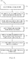
- FIG. 5 is a flowchart illustrating an exemplary method 130 suitable for producing turbine nozzle 20 shown in FIGs. 1-4 .
- Exemplary method 130 is provided by way of non-limiting illustration only with the understanding that embodiments of the turbine nozzle described herein can be produced utilizing various different types of manufacturing processes.
- Exemplary method 130 commences with the production of outer ring 60 , inner ring 62 , and vanes 64 (STEP 132 ).
- Outer ring 60 and inner ring 62 may be obtained (whether by independent fabrication or purchase from a supplier) in a near net form.
- outer ring 60 and inner ring 62 are each cast as monolithic or continuous annular structures.
- a bond coat e.g., bond coats 110 and 112 shown in FIG.
- slots 78 may be formed in inner ring 62 utilizing, for example, an Electrical Discharge Machining (EDM) plunging technique.
- Vanes 64 may b individually cast from a chosen superalloy, such as a single crystal superalloy.
- cooling holes may be formed in vanes 64 (e.g., cooling holes 91 shown in FIG. 3 ) utilizing, for example, an EDM drilling technique.
- turbine nozzle 20 may be assembled utilizing a specialized fixture or mold.
- the separately-cast vanes 64 may be inserted into radial openings provided in outer ring 60 and then joined thereto utilizing, for example, a brazing process. This results in the formation of braze joints 138 (identified in FIG. 3 ) between the adjoining surfaces of vanes 64 and outer ring 60 .
- Bores 94 and 96 may then be formed in vanes 64 and inner ring 62 , respectively, utilizing an EDM drilling process; and radial retention pins 90 ( FIGs.
- braze joints 142 may be installed through bores 94 and 96 (STEP 140 ) by, for example, inserting pins 90 in a radial direction through vanes 64 and then deforming or bonding an inner enlarged head 98 to each pin shank 92 . Tack welds may be utilized to secure retention pins 90 in their desired position in an embodiment. Also, during STEP 140 , cooling tubes 86 may be inserted into the inner cavities of vanes 64 and secured in place utilizing, for example, an additional brazing process to form braze joints 142 (identified in FIG. 3 ).
- the braze process may also melt or soften any braze material (e.g., a strip of braze foil) utilized to bond retention pins 90 to vanes 64 and/or to inner ring 62 .
- any braze material e.g., a strip of braze foil
- the selected oxidation-resistant sealing material may be infiltrated into slip joints 79 to produce annular seal layers 118 (STEP 144 ), as described below.
- Oxidation-resistant seal layers 118 are preferably formed within slip joints 79 utilizing a slurry application process.
- the selected sealant material may be mixed in powder form with a liquid carrier, such as alcohol or water, or in an organic binder with a viscosity tailored to form a flowable slurry.
- the slurry may then be applied around the mouth or exposed end of slip joints 79 utilizing brushing, spraying, needle dispensing, or similar application technique.
- the wet-state sealant material flows into slip joints 79 due to capillary action.
- turbine nozzle 20 can be positioned on its side and spun at a low rate of speed to create centrifugal forces assisting inflow of the wet-state sealant material into slip joints 79 .
- the sealant material is preferably applied in sufficient volume to flow into joints 79 to a depth substantially equivalent to the radial length of airfoil extension 84 to form a robust seal, while leaving an air pocket within the bottom of each slot 78 to allow sliding radial movement of vane 64 with respect to inner ring 62 .
- a heat treatment process may be carried-out after deposition of the wet-state sealant material to evaporate the binder material and, perhaps, to decompose any other organic materials contained within the slurry and thereby form oxidation-resistant seal layer 118 .
- heat treatment of the wet-state sealant material may occur during subsequent processing of turbine nozzle 20 (e.g., during the below-described formation of the TBC coating). Heat treatment may also be carried-out to promote diffusion of oxidation-resistant seal layer 118 into bond coats 110 and 112 ( FIG. 4 ), when present; e.g., in one embodiment, seal layer 118 may be heated to a temperature of approximately 930°C for a time period of about two hours. During any such heat treatment step, oxidation-resistant seal layer 118 is still preferably not heated above the melt point of the metallic powders contained within the slurry; e.g., any heat treatment step may entail processing temperatures below 1100°C.
- a TBC coating (e.g., TBC coating 114 and 116 shown in FIG. 4 ) may be formed over the gas-exposed surfaces of turbine nozzle 20 (STEP 146 ).
- the TBC coating is applied utilizing a vapor deposition technique, such as electron beam physical vapor deposition.
- additional processing steps may be performed to complete fabrication of turbine nozzle 20 (STEP 148 ). Such additional processing steps may include additional heat treatment steps (e.g., aging or diffusion cycles) and/or final machining steps.
- the resulting turbine nozzle 20 may then be inspected and ultimately installed within a gas turbine engine, such as GTE 18 shown in FIG. 1 , utilizing a plurality of bolts or other such fasteners.
- silicon-modified aluminide sealing materials can be applied in slurry form after assembly of the turbine nozzle thereby enabling (in some embodiments) the nozzle to be produced utilizing a bi-casting process wherein the inner and outer rings are separately cast or otherwise fabricated as monolithic structures prior to turbine nozzle assembly.
- the silicon-modified aluminide sealing materials are further well-suited for application over and diffusion into platinum-aluminide bond coats, which may be applied prior to assembly of the turbine the nozzle.
Landscapes
- Engineering & Computer Science (AREA)
- Mechanical Engineering (AREA)
- General Engineering & Computer Science (AREA)
- Turbine Rotor Nozzle Sealing (AREA)
Description
- This invention was made with Government support under W911W6-08-2-0001 awarded the U.S. Army. The Government has certain rights in the invention.
- The following disclosure relates generally to gas turbine engines and, more particularly, to turbine nozzles and methods for producing turbine nozzles having slip joints impregnated with an oxidation-resistant sealing material, such as a silicon-modified aluminide sealing material.
- Gas turbine engine are often produced to include turbine nozzles, which meter combustive gas flow, while also accelerating and turning the gas flow toward the blades of a turbine rotor positioned downstream of the nozzle. A turbine nozzle may be assembled from a number of separately-produced segments, which each include an arced segment of the inner endwall or ring, an arced segment of the outer endwall or ring, and one or more airfoils or vanes extending therebetween. Turbine nozzles of this type (referred to herein as "segmented turbine nozzles") may, however, be prone to gas flow leakage across the mating interfaces between adjoining segments and flange surfaces. Gas flow leakage may increase chargeable cooling flow to the cycle, reduce cooling flow from the combustor, and result in a direct penalty against overall gas turbine engine performance. As an alternative to segmented turbine nozzles, bi-cast turbine nozzles have been developed in which inner and outer rings are cast as unitary structures, which lack segment-to-segment interfaces across which leakage may occur. During production of a bi-cast turbine nozzle, the vanes are individually produced and then positioned in a mold for bonding to the inner ring and/or the outer ring. In certain cases, the vanes may only be affixed to one of the rings, while forming slip joints with the ring to which the vanes are not affixed. Such slip joints help alleviate thermomechanical fatigue by permitting relative radial movement between the turbine nozzle vanes and the turbine nozzle attachment points as thermal gradients develop across the turbine nozzle during operation of the gas turbine engine.
- While providing the above-noted advantages, bi-cast turbine nozzles remain limited in certain respects. For example, by virtue of the manner in which the bi-cast turbine nozzles are produced, the application of the Thermal Barrier Coating (TBC) typically occurs after assembly of the turbine nozzle and bonding of the vanes. When the turbine nozzle is produced to include slip joints, the interior surfaces defining the slip joints may remain uncoated by the TBC. Unfilled clearances or air gaps may thus remain around the floating terminal ends of the vanes bounding the slip joints. During gas turbine engine operation, hot combustive gasses may be ingested into these gaps from the pressure side of the vane, flow underneath the vane footprint, and discharge to the suction side of the vane. Hot gas ingestion may cause oxidative damage to the slip joint surfaces and detract from the aerodynamic performance of the turbine nozzle. Over the lifespan of the turbine nozzle, oxidation and hot corrosion may further erode the uncoated surfaces of the slip joints resulting in increasingly large air gaps and still further reductions in the aerodynamic performance of the turbine nozzle.
- It is thus desirable to provide embodiments of a method for manufacturing turbine nozzles including slip joints, which minimize hot gas ingestion into the slip joints and which provide oxidation and hot corrosion resistance during operation of the gas turbine engine. It would also be desirable if, in at least some embodiments, the manufacturing method enabled the production of bi-cast turbine nozzles; that is, turbine nozzles wherein the inner and outer rings are separately cast as unitary structures. It would also be desirable to provide embodiments of a turbine nozzle produced in accordance with such a fabrication method. Other desirable features and characteristics of the present invention will become apparent from the subsequent Detailed Description and the appended Claims, taken in conjunction with the accompanying Drawings and the foregoing Background.
- United States Patent
5634767, June 3 1997 by John Dawson discloses a turbine frame with annular outer and inner liners adjoined to outer and inner bands A plurality of telescopic outer and inner joints support the liners to the bands and allow unrestrained differential thermal radial movement. - European Patent Application
1820875A2 22 August 2007 , General Electric Company, discloses a gas turbine engine turbine blade, and a method for coating parts of the blade with a silicon modified diffusion aluminide layer. - Embodiments of a method for manufacturing a turbine nozzle having slip joints impregnated by an oxidation-resistant sealing material are provided. In one embodiment, the method includes providing a support ring, a slip joint ring substantially concentric with the support ring and radially spaced apart therefrom, and a plurality of vanes fixedly coupled to the support ring. The plurality of vanes extends radially from the support ring into a plurality of circumferentially-spaced slots in the slip joint ring to form a plurality of slip joints therewith. The plurality of slip joints are impregnated with a silicon-modified aluminide sealing material. The silicon-modified aluminide sealing material impedes gas flow into the radial slip joints during operation of the turbine nozzle, while also fracturing to permit relative radial movement between the plurality of vanes and the slip joint ring along the plurality of slip joints.
- Embodiments of a turbine nozzle are also provided. In one embodiment, the turbine nozzle includes a support ring and a slip joint ring, which is substantially concentric with the support ring and radially spaced apart therefrom. The slip joint ring has a plurality of circumferentially-spaced slots therein. A plurality of vanes is fixedly coupled to the support ring and extends radially therefrom into the plurality of circumferentially-spaced slots such that a plurality of radial slip joints is formed between the plurality of vanes and the plurality of circumferentially-spaced slots. A silicon-modified aluminide sealing material is impregnated into the plurality of radial slip joints. The silicon-modified aluminide sealing material impedes gas flow into the radial slip joints during operation of the turbine nozzle, while fracturing to permit relative radial movement between the plurality of vanes and the slip joint ring.
- At least one example of the present invention will hereinafter be described in conjunction with the following figures, wherein like numerals denote like elements, and:
-
FIG. 1 is a cross-sectional schematic of an exemplary gas turbine engine including a turbine nozzle, which can be produced in accordance with an embodiment of the fabrication process described herein; -
FIGs. 2 and3 are isometric and cross-sectional views, respectively, of a portion of the turbine nozzle included in the gas turbine engine shown inFIG. 1 , as illustrated in accordance with an exemplary embodiment; -
FIG. 4 is a cross-sectional view of a portion of the turbine nozzle shown inFIGs. 2-3 illustrating, in greater detail, one manner in which the slip joints may be impregnated with a slurry-applied, oxidation-resistant sealing material in accordance with embodiments of the present invention; and -
FIG. 5 is a flowchart setting-forth an exemplary method suitable for producing a turbine nozzle including slip joints impregnated with slurry-applied, oxidation-resistant sealing material, as illustrated in accordance with an exemplary embodiment of the present invention. - For simplicity and clarity of illustration, the drawing figures illustrate the general manner of construction, and descriptions and details of well-known features and techniques may be omitted to avoid unnecessarily obscuring the invention. Additionally, elements in the drawings figures are not necessarily drawn to scale. For example, the dimensions of some of the elements or regions in the figures may be exaggerated relative to other elements or regions to help improve understanding of embodiments of the invention.
- The following Detailed Description is merely exemplary in nature and is not intended to limit the invention or the application and uses of the invention. Furthermore, there is no intention to be bound by any theory presented in the preceding Background or the following Detailed Description. Terms such as "comprise," "include," "have," and variations thereof are utilized herein to denote non-exclusive inclusions. Such terms may thus be utilized in describing processes, articles, apparatuses, and the like that include one or more named steps or elements, but may further include additional unnamed steps or elements. The term "radial slip joint," the term "slip joint," and similar terms and phrases are utilized to denote an interface created between two closely positioned surfaces allowing relative radial movement therebetween. The closely positioned surfaces may be separated by an air gap or, instead, intervening structural elements and/or materials (e.g., sealing materials of the type described below) may be disposed between the neighboring surfaces.
-
FIG. 1 is a cross-sectional schematic of an exemplary gas turbine engine (GTE) 18 including aturbine nozzle 20, which may be produced in accordance with the fabrication process described in detail below in conjunction withFIG. 5 . By way example, GTE 18 is illustrated inFIG. 1 as a two spool turbofan engine including anintake section 22, acompressor section 24, acombustion section 26, aturbine section 28, and anexhaust section 30.Intake section 22 includes anintake fan 32 mounted in anacelle assembly 34. In the illustrated example,compressor section 24 includes a singleaxial compressor 36, which is rotatably disposed within anengine case 38 mounted withinnacelle assembly 34.Turbine section 28 includes a high pressure (HP)turbine 40 and a low pressure (LP)turbine 42, which are rotatably disposed withinengine case 38 in flow series.Turbine nozzle 20 is disposed downstream ofcombustion section 26 and immediately upstream of HPturbine 40. Although not shown inFIG. 1 , a second turbine nozzle may likewise be disposed upstream ofLP turbine 42.Compressor 36 and HPturbine 40 are mounted to opposing ends of anHP shaft 44, andintake fan 32 andLP turbine 42 are mounted to opposing ends of aLP shaft 46.LP shaft 46 and HPshaft 44 are co-axial; that is,LP shaft 46 extends through a longitudinal channel provided through HPshaft 44.Engine case 38 andnacelle assembly 34 terminate in amixer nozzle 48 and apropulsion nozzle 50, respectively.Mixer nozzle 48 cooperates with a centerbody 52 to form anexhaust mixer 54, which mixes hot combustive gas flow received fromturbine section 28 with cooler bypass airflow during operation of GTE 18. - As illustrated in
FIG. 1 and described herein, GTE 18 is offered by way of non-limiting example only. It will be readily appreciated that turbine nozzles of the type described herein can be utilized within various other types of gas turbine engine including, but not limited to, other types of turbofan, turboprop, turboshaft, and turbojet engines, whether deployed onboard an aircraft, watercraft, or ground vehicle (e.g., a tank), included within an auxiliary power unit, included within industrial power generators, or utilized within another platform or application. With respect to exemplary GTE 18, in particular, it is noted that the particular structure of GTE 18 will inevitably vary amongst different embodiments. For example, in certain embodiments, GTE 18 may include an exposed intake fan (referred to as an "open rotor configuration") or may not include an intake fan. In other embodiments, GTE 18 may employ centrifugal compressors or impellers in addition to or in lieu of axial compressors. In still further embodiments, GTE 18 may include a single shaft or three or more shafts along with varying numbers of compressors and turbines. - During operation of GTE 18, air is drawn into
intake section 22 and accelerated byintake fan 32. A portion of the accelerated air is directed through abypass flow passage 56, which is provided betweennacelle assembly 34 andengine case 38 and conducts this airflow over and aroundengine case 38. The remaining portion of air exhausted fromintake fan 32 is directed intocompressor section 36 and compressed bycompressor 36 to raise the temperature and pressure of the core airflow. The hot, compressed airflow is supplied tocombustion section 26 wherein the air is mixed with fuel and combusted utilizing one or more combustors 58 included withinsection 26. The combustive gasses expand rapidly and flow throughturbine section 28 to drive the rotation ofHP turbine 40 andLP turbine 42.Turbine nozzle 20 further accelerates the combustive gas flow and helps to impart the gas flow with a desired tangential component prior to impingement upon the rotating blades ofHP turbine 40. The rotation ofturbines shafts compressor 36 andintake fan 32. The rotation ofshafts turbine section 28, the combustive gas flow is then directed intoexhaust section 30 whereinmixer 54 mixes the combustive gas flow with the cooler bypass air received frombypass flow passages 56. Finally, the combustive gas flow is exhausted from GTE 18 throughpropulsion nozzle 50 to produce forward thrust, although this may not be the case in alternative embodiments wherein GTE 18 assumes the form of, for example, a turboshaft engine. -
FIG. 2 is an isometric view of a portion ofturbine nozzle 20, as illustrated in accordance with an exemplary embodiment of the present invention.Turbine nozzle 20 includes an outer ring 60 (also commonly referred to as an "outer endwall" or "outer shroud"), an inner ring 62 (also commonly referred to as an "inner endwall" or "inner shroud"), and a plurality of airfoils orvanes 64.Outer ring 60 circumscribes, is radially spaced apart from, and is substantially concentric withinner ring 62.Outer ring 60,inner ring 62, andvanes 64 may be assembled such thatvanes 64 are affixed to eitherring 60 orring 62 and form slip joints with the opposing ring, as described in detail below.Turbine nozzle 20 may be fabricated to include any number of flanges or other structural elements to facilitate mounting and piloting to the static infrastructure of GTE 18; e.g., as shown inFIG. 2 , and provided solely by way of example,turbine nozzle 20 may be fabricated to include a first leadingflange 72 extending radially outward from the forward circumferential edge ofouter ring 60, a second leadingflange 74 extending radially inward from the forward circumferential edge ofinner ring 62, and a trailingflange 76 extending radially outward from the aft circumferential edge ofouter ring 60. -
Nozzle vanes 64 extend radially betweenouter ring 60 andinner ring 62 to define a number of combustivegas flow paths 68 through the body of turbine nozzle 20 (four of which can be seenFIG. 2 ). Eachgas flow path 68 is defined by a different pair of adjacent or neighboringvanes 64; an inner surface ofouter ring 60 located between the neighboringvanes 64, as taken in a radial direction; and an interior surface region ofinner ring 62 located between the neighboringvanes 64, as taken in a radial direction.Gas flow paths 68 extend throughturbine nozzle 20 in axial and tangential directions to guide combustive gas flow through the body ofnozzle 20, while turning the gas flow toward the blades of HP turbine rotor 40 (FIG. 1 ).Gas flow paths 68 may constrict or decrease in cross-sectional flow area when moving in a fore-aft direction along which combustive gas flows during engine operation. Eachflow path 68 thus serves as a convergent nozzle to meter and accelerate combustive gas flow throughturbine nozzle 20. - Although only limited sections of
rings FIG. 2 , it will be appreciated that rings 60 and 62 are annular structures, which are generally axisymmetric with respect to the rotational axis of GTE 18 and which extend fully therearound. In embodiments whereinturbine nozzle 20 is produced utilizing a bi-casting process of the type described below in conjunction withFIG. 5 , rings 60 and 62 are cast as monolithic or continuous structures, which (in contrast to the rings of a segmented turbine nozzle) are uninterrupted by mating interfaces between adjoining segments. By virtue of this construction, leakage throughturbine nozzle 20 and, specifically, leakage in radial directions acrossrings FIG. 1 ) to optimize overall engine performance. This notwithstanding, embodiments ofturbine nozzle 20 can be produced utilizing other types of fabrication methods suitable for producing slip joints impregnated with an oxidation-resistant sealing material of the type described below. -
Inner ring 62 is fabricated to include a number of circumferentially-spaced cavities, depressions, orslots 78, which matingly receive the inner terminal ends ofvanes 64 and cooperate therewith to produce a number of radial slip joints 79. The portions ofturbine nozzle vane 64 extending between the inner circumferential surface ofouter ring 60 and the outer circumferential surface ofinner ring 62 are identified byreference numeral 80 and are referred to hereafter as the "main airfoil portions." By comparison, the portions ofturbine nozzle vane 64 received within slots 78 (the floating terminal ends of vanes 64) are identified byreference numeral 82 and are referred to hereafter as the "airfoil extensions." A first end ofmain airfoil portion 80 is fixedly attached to (e.g., bonded to or integrally formed with)outer ring 60; e.g., in the illustrated example, the radially-outer end ofmain airfoil portion 80 is bonded toouter ring 60 utilizing, for example, a brazing process of the type described below. The opposing end of main airfoil portion 80 (the radially-inner end ofmain airfoil portion 80 inFIG. 2 ) is fixedly joined toairfoil extension 82 and is preferably integrally formed therewith as a single cast piece. The outer circumferential surface ofairfoil extension 82 and the inner circumferentialsurface defining slot 78 create a relatively small clearance at the circumferential interface between theturbine nozzle vane 64 andinner ring 62. This circumferential clearance is shown more clearly inFIGs. 3 and 4 , as described below. - The ring or annular endwall to which
turbine nozzle vanes 64 are affixed may be referred to herein as the "support ring," while the slotted ring or annular endwall forming radial slip joints withvanes 64 may be referred to herein as the "slip joint ring." In keeping with this terminology, the following description of theexemplary turbine nozzle 20 shown inFIGs. 2-4 will refer toouter ring 60 as "outer support ring 60" or, more simply, "support ring 60"; and toinner ring 62 as "inner slipjoint ring 62" or, more simply, "slipjoint ring 62." The exemplary embodiment shown inFIGs. 2-4 notwithstanding, it should be appreciated that embodiments ofturbine nozzle 20 can be fabricated whereinturbine nozzle vanes 64 are affixed to (e.g., integrally formed with or bonded to) the inner ring and form radial slip joints with the outer ring. In such embodiments, the inner ring would be considered the "support ring," while the outer ring would be considered the "slip joint ring." Furthermore, the term "slot," as appearing herein, denotes any penetrating or non-penetrating opening, pocket, depression, or cavity formed in a slip joint ring that can cooperate with a turbine nozzle vane to form a slip joint of the type described herein. The slots will often assume the form of depressions having a planform shape conformal with that of the airfoil extensions and having an angularly spacing corresponding to that of the turbine nozzle vanes. The slots may be formed in or through the inner circumferential surface of the slip joint ring when the slip joint ring is the outermost ring of the turbine nozzle. Conversely, the slots may be formed in or through the outer circumferential surface of the slip joint ring when the slip joint ring is the innermost ring of the turbine nozzle. - With continued reference to the exemplary embodiment shown in
FIG. 2 ,main airfoil portion 80 has a cross-sectional airfoil shape, which conditions combustive gas flow throughturbine nozzle 20.Main airfoil portion 80 andairfoil extension 82 may have similar circumferential profiles or planform shapes. It is, however, preferred thatairfoil extension 82 has an enlarged and gradually contoured circumferential profile, as compared tomain airfoil portion 80, to lower tolerances and to allow a mating or conformal fit, and therefore a more uniform gap width, to be more easily created betweenairfoil portion 80 and the surrounding sidewalls defining eachslot 78. For this reason, eachairfoil extension 82 may be imparted with a substantially elliptical or ovular circumferential profile; and eachslot 78 may likewise be formed to have a substantially elliptical or ovular circumferential profile. Such a gradually contoured surface and substantially uniform gap width also facilitates the deposition of sealing material into the slip joint to deter the inflow of combustive gasses intoslots 78 during operation ofturbine nozzle 20. The outer exposed surface ofairfoil extension 82 may be contoured to form a smooth, substantially uninterrupted flow path withinner ring 62. As noted above,main airfoil portion 80 andairfoil extension 82 are preferably (although not necessarily) integrally formed as a single cast piece. -
FIG. 3 is a cross-sectional view ofturbine nozzle 20, taken along a cut plane through one ofvanes 64. Certain additional structure features can be seen inFIG. 3 , which were omitted or hidden from view inFIG. 2 . These additional structures features include: (i) an inner cavity or hollow 86 provided in eachvane 64, (ii) acooling tube 88, which may be inserted into and nest within each hollow 86, and (iii) cooling channels orapertures 91, which may be provided through the sidewall ofvanes 64. As further shown inFIG. 3 , a plurality of radial retention pins 92 may be further provided between the floating terminal ends ofvanes 64 andinner support ring 62 proximate slip joints 79. Radial retention pins 92 serve to prevent separation ofairfoil extensions 84 from inner slipjoint ring 62 in the unlikely event of airfoil burn-through. During assembly ofturbine nozzle 20, retention pins 92 are inserted into aligning openings or radial bores 94 and 96 provided through terminal ends ofvanes 64 and through the annular sidewall ofinner ring 62, respectively. Thus, in the illustrated embodiment, radial retention pins 92 extend along axes substantially perpendicular to the longitudinal axis ofturbine nozzle 20 fromairfoil extensions 82, through radial pockets orgaps 100 provided under airfoil extension 82 (described below), and toinner ring 62. Retention pins 92 are each produced to include opposingenlarged heads 98, one of which is disposed within the inner cavity or hollow provided in avane 64 and the other of which is disposed adjacent the inner circumference ofinner ring 62. Enlarged pin heads 98 each have an outer diameter larger than the diameters ofbores pins 92 in their desired position. At the same time, the shanks ofpins 92 are provided with sufficient lengths to allow eachpin 92 to slide radially with respect to itscorresponding bore 96 to avoid obstructing relative radial displacement betweenvanes 64 andinner ring 62 during heating ofturbine nozzle 20. In this manner,radial retention pins 92 slidably attachvanes 64 toinner ring 62 to permit relative radial movement betweenvanes 64 and ring, while retainingvanes 64 if airfoil burn-through should occur. If desired, retention pins 92 may be bonded to theircorresponding vanes 64 utilizing, for example, strips of braze foil (not shown). - As indicated above, radial slip joints 79 are bound along their inner perimeter or circumference by
airfoil extensions 82 and along their outer perimeter or circumference by the inner surfaces ofinner ring 62 definingslots 78. A relatively small circumferential clearance or annular gap is created at the circumferential interface between theturbine nozzle vane 64 and slipjoint ring 62. By comparison, a relatively largeradial gap 100 is provided between the terminal end surface of airfoil extension 84 (i.e., the radially-inner end ofairfoil extension 84 in the illustrated example) and the floor ofslot 78 to accommodate relative radial movement between theturbine nozzle vane 64 and slipjoint ring 62. Whileairfoil extensions 84 andslots 78 can be produced to relatively tight tolerances such that the circumferential gap or clearance between eachextension 84 and itsrespective slot 78 is relatively small (e.g., on the order of 0.002 to 0.003 inch), gas flow leakage intoslots 78 can still occur. Such gas flow leakage reduces the efficiency ofturbine nozzle 20 and can potentially cause structural degradation due to hot gas corrosion, oxidation, thermal fatigue, erosion, and the like. Thus, to minimize gas inflow into radial slip joints 79, the circumferential clearances betweenairfoil extensions 84 and surroundingslots 78 are impregnated or infiltrated with an oxidation-resistant sealing material of the type described below. - The sealing material impregnated into radial slip joints 79 is preferably chosen or prevent interference with the sliding radial movement of the slip joints, to have a relatively high melt point to prevent melting or softening during operation of
turbine nozzle 20, and to be reliably retained within the slips joints by, for example, formation of a relatively strong bond with the inner peripheral surfaces ofslots 78 or the outer peripheral surfaces of airfoil extensions 84 (or a bond coat formed thereof, as described below in conjunction withFIG. 4 ). In certain embodiments, the selected sealing material or materials may initially be bonded to both the inner peripheral surfaces ofslots 78 and the outer peripheral surfaces ofairfoil extensions 84. However, in this case, a purposefully weak bond is created between the sealing material and the inner peripheral surfaces ofslots 78 or the outer peripheral surface ofairfoil extensions 84 such that the sealing material separates therefrom during operation of theturbine nozzle 20 to permit the desired slippage. Alternatively, the sealing material may be bonded to both the inner peripheral surfaces ofslots 78 and the outer peripheral surface ofairfoil extensions 84 and may fracture radially during usage to accommodate relative radial movement betweenairfoil extensions 84 and slipjoint ring 62. - It is possible to impregnate radial slip joints 79 with a high temperature braze material. Examples of braze materials suitable for this process are described in copending
U.S. App. Serial No. 13/719,566 slip joints 79, such braze materials may be prone to excessive oxidation and hot corrosion during operation of the gas turbine engine. Additionally, such braze materials are often applied as a relatively complex, multilayer coating system including a grit-blasted layer and/or a thermally-grown oxide layer in addition to an underlying bond coat layer. It has been discovered that certain non-braze,
oxidation-resistant sealing materials can be utilized to seal radial slip joints 79, while still providing the ability to smoothly fracture under relatively low shear loads and thus permit the desired radial movement betweenvanes 64 and inner slipjoint ring 62. Advantageously, such oxidation-resistant sealing materials can be applied in slurry form and need not be subject to high temperature thermal processing surpassing the melt or softening point of the sealing material. In preferred embodiment, the oxidation-resistant sealing material is a silicon-modified aluminide material; that is, a material containing an aluminide as its primary metallic constituent, as well as at least five weight percent (5 wt%) silicon. Examples of suitable silicon-modified aluminide sealing materials are further discussed below. Such materials may be applied utilizing a relatively simple coating system (e.g., a coating system consisting of the sealing material and a single bond coat layer) or may be applied directly over the selected surfaces without additional coating layers thereby reducing the cost and duration of the turbine nozzle manufacturing process. -
FIG. 4 is a more detailed cross-sectional view of the slip joint 79 shown inFIG. 3 , which further illustrates a slip joint coating system that may be formed over selected surfaces of slip joint 79 (and the other non-illustrated slip joints included withinturbine nozzle 20 shown inFIGs. 1-3 ). As can be seen, a firstbond coat layer 110 has been formed over the interior surfaces ofinner ring 62 defining the outer boundaries ofslot 78. Similarly, a secondbond coat layer 112 has been formed over the exterior surfaces ofairfoil extension 94 defining the inner boundaries ofslot 78. Bond coat layers 110 and 112 may be, for example, platinum aluminide (PtAl) layers or nickel-platinum aluminide layers (NiPtAl) formed utilizing a thermal spray process or other deposition process. By way of non-limiting example, bond coat layers 110 and 112 may be deposited to a thickness between about 0.0015 and about 0.0030 inch in an embodiment. In further embodiments, either or both of bond coat layers 110 and 112 may be omitted. When included withinturbine nozzle 20, bond coat layers 110 and 112 may be formed prior to assembly ofnozzle 20, as descried below in conjunction withFIG. 5 . In this case,bond coat layer 112 may terminate at or nearmain airfoil portion 82 ofvane 64, which may be coated with a Thermally-Grown Oxide (TGO)layer 114. Similarly,bond coat layer 110 may terminate at or near the inner circumferential surface ofinner ring 62 defininggas flow paths 68, which may likewise be coated with aTGO layer 116. - An oxidation-resistant sealing material is impregnated into slip joint 79 to form a seal layer 118 (essentially, a fracturable annular seal) between bond coat layers 110 and 112, when present. As described more fully below in conjunction with
FIG. 5 , the oxidation-resistant sealing material may be applied in a wet-state as a slurry, which is drawn into the circumferential gap provided between bond coat layers 110 and 112. The oxidation-resistant sealing material may then be dried and diffused into bond coat layers 110 and 112 (when present) at temperatures below the melt point of the material to form oxidation-resistant seal layer 118. As noted above, a silicon-modified aluminide material is preferably utilized to form oxidation-resistant seal layer 118. Such a silicon-modified aluminide layer provides excellent chemical compatibility withbond coats resistant seal layer 118 is commercially marketed under the name "SERMALOY™ J" by Praxair Surface Technologies, Inc., headquartered in Indianapolis, IN. While commercially-available, this material has traditionally been utilized in high temperature coating applications and not as a fracture-prone gap fill material. In an embodiment, oxidation-resistant seal layer 118 is formed to have a thickness between about 0.001 and about 0.003 inch; the term "about," as appearing herein, denoting a disparity of less than 10%. In further embodiments,seal layer 118 may be thicker or thinner than the aforementioned range. - As indicated above, oxidation-
resistant seal layer 118 forms a mechanically weak joint or body, which is prone to fracture when subject to sheer forces. As generally illustrated inFIG. 4 , cracks or fractures develop within oxidation-resistant seal layer 118 between bond coat layers 110 and 112 (if present) and, more generally, between the interior surfaces of radial slip joints 79. Such fractures accommodate the relative radial movement occurring betweenturbine nozzle vane 64 and inner slipjoint ring 62 when the turbine nozzle is exposed to hot combustive gas flow (as indicated inFIG. 4 by doubleheaded arrow 120). At the same time, such fractures are relatively tight or constricted and, thus, minimize hot gas ingestion into the unfilled space, clearance, or air pocket created in slip joints 79, which is located radially adjacent oxidation-resistant seal layer 118 and between the floating terminal ends ofairfoil extensions 84 and the floors ofslots 78. In this manner, hot gas ingestion into slip joints 79 is minimized when combustive gas flow is directed throughnozzle 20 alonggas flow paths 68 during operation of turbine nozzle 20 (represented inFIG. 3 by arrows 122). -
FIG. 5 is a flowchart illustrating anexemplary method 130 suitable for producingturbine nozzle 20 shown inFIGs. 1-4 .Exemplary method 130 is provided by way of non-limiting illustration only with the understanding that embodiments of the turbine nozzle described herein can be produced utilizing various different types of manufacturing processes.Exemplary method 130 commences with the production ofouter ring 60,inner ring 62, and vanes 64 (STEP 132).Outer ring 60 andinner ring 62 may be obtained (whether by independent fabrication or purchase from a supplier) in a near net form. In preferred embodiments,outer ring 60 andinner ring 62 are each cast as monolithic or continuous annular structures. A bond coat (e.g.,bond coats FIG. 4 ) may be applied to all exterior surfaces ofrings 60 and 62 (STEP 134). Afterwards, surfaces ofrings Rings turbine nozzle 20. For example,slots 78 may be formed ininner ring 62 utilizing, for example, an Electrical Discharge Machining (EDM) plunging technique.Vanes 64 may b individually cast from a chosen superalloy, such as a single crystal superalloy. If desired, cooling holes may be formed in vanes 64 (e.g., cooling holes 91 shown inFIG. 3 ) utilizing, for example, an EDM drilling technique. - Next, at
STEP 136 of exemplary method 130 (FIG. 5 ),turbine nozzle 20 may be assembled utilizing a specialized fixture or mold. During assembly, the separately-cast vanes 64 may be inserted into radial openings provided inouter ring 60 and then joined thereto utilizing, for example, a brazing process. This results in the formation of braze joints 138 (identified inFIG. 3 ) between the adjoining surfaces ofvanes 64 andouter ring 60.Bores 94 and 96 (FIGs. 3 and 4 ) may then be formed invanes 64 andinner ring 62, respectively, utilizing an EDM drilling process; and radial retention pins 90 (FIGs. 3 and 4 ) may be installed throughbores 94 and 96 (STEP 140) by, for example, insertingpins 90 in a radial direction throughvanes 64 and then deforming or bonding an innerenlarged head 98 to eachpin shank 92. Tack welds may be utilized to secure retention pins 90 in their desired position in an embodiment. Also, during STEP 140, coolingtubes 86 may be inserted into the inner cavities ofvanes 64 and secured in place utilizing, for example, an additional brazing process to form braze joints 142 (identified inFIG. 3 ). The braze process may also melt or soften any braze material (e.g., a strip of braze foil) utilized to bond retention pins 90 tovanes 64 and/or toinner ring 62. Withturbine nozzle 20 now fully assembled, the selected oxidation-resistant sealing material may be infiltrated intoslip joints 79 to produce annular seal layers 118 (STEP 144), as described below. - Oxidation-resistant seal layers 118 are preferably formed within slip joints 79 utilizing a slurry application process. In this regard, the selected sealant material may be mixed in powder form with a liquid carrier, such as alcohol or water, or in an organic binder with a viscosity tailored to form a flowable slurry. The slurry may then be applied around the mouth or exposed end of
slip joints 79 utilizing brushing, spraying, needle dispensing, or similar application technique. The wet-state sealant material flows intoslip joints 79 due to capillary action. Additionally, if desired,turbine nozzle 20 can be positioned on its side and spun at a low rate of speed to create centrifugal forces assisting inflow of the wet-state sealant material into slip joints 79. As indicated inFIG. 4 , the sealant material is preferably applied in sufficient volume to flow intojoints 79 to a depth substantially equivalent to the radial length ofairfoil extension 84 to form a robust seal, while leaving an air pocket within the bottom of eachslot 78 to allow sliding radial movement ofvane 64 with respect toinner ring 62. In certain cases, a heat treatment process may be carried-out after deposition of the wet-state sealant material to evaporate the binder material and, perhaps, to decompose any other organic materials contained within the slurry and thereby form oxidation-resistant seal layer 118. Alternatively, heat treatment of the wet-state sealant material may occur during subsequent processing of turbine nozzle 20 (e.g., during the below-described formation of the TBC coating). Heat treatment may also be carried-out to promote diffusion of oxidation-resistant seal layer 118 intobond coats 110 and 112 (FIG. 4 ), when present; e.g., in one embodiment,seal layer 118 may be heated to a temperature of approximately 930°C for a time period of about two hours. During any such heat treatment step, oxidation-resistant seal layer 118 is still preferably not heated above the melt point of the metallic powders contained within the slurry; e.g., any heat treatment step may entail processing temperatures below 1100°C. - After application of oxidation-
resistant seal layer 118, a TBC coating (e.g.,TBC coating FIG. 4 ) may be formed over the gas-exposed surfaces of turbine nozzle 20 (STEP 146). In one embodiment, the TBC coating is applied utilizing a vapor deposition technique, such as electron beam physical vapor deposition. Afterwards, additional processing steps may be performed to complete fabrication of turbine nozzle 20 (STEP 148). Such additional processing steps may include additional heat treatment steps (e.g., aging or diffusion cycles) and/or final machining steps. The resultingturbine nozzle 20 may then be inspected and ultimately installed within a gas turbine engine, such as GTE 18 shown inFIG. 1 , utilizing a plurality of bolts or other such fasteners. - The foregoing has thus provided embodiments of a method for manufacturing turbine nozzles including slip joints, which are impregnated with an oxidation-resistant gap fill material and, preferably, a silicon-modified aluminide sealing material. As do other filler materials (e.g., braze materials), such materials impeding gas flow into the radial slip joints during operation of the turbine nozzle, while fracturing to permit relative radial movement between the plurality of vanes and the slip joint ring along the plurality of slip joints. However, in contrast to many braze materials, the silicon-modified aluminide sealing materials provide superior oxidation and corrosion protection in the gas turbine engine environment to minimize gradual surface erosion and thereby maintain the aerodynamic performance of the turbine nozzle over a longer operational lifespan. Additionally, such silicon-modified aluminide sealing materials can be applied in slurry form after assembly of the turbine nozzle thereby enabling (in some embodiments) the nozzle to be produced utilizing a bi-casting process wherein the inner and outer rings are separately cast or otherwise fabricated as monolithic structures prior to turbine nozzle assembly. The silicon-modified aluminide sealing materials are further well-suited for application over and diffusion into platinum-aluminide bond coats, which may be applied prior to assembly of the turbine the nozzle.
- While multiple exemplary embodiments have been presented in the foregoing Detailed Description, it should be appreciated that a vast number of variations exist. It should also be appreciated that the exemplary embodiment or exemplary embodiments are only examples, and are not intended to limit the scope, applicability, or configuration of the invention in any way. Rather, the foregoing Detailed Description will provide those skilled in the art with a convenient road map for implementing an exemplary embodiment of the invention. It being understood that various changes may be made in the function and arrangement of elements described in an exemplary embodiment without departing from the scope of the invention as set-forth in the appended Claims.
Claims (10)
- A method (130) for manufacturing a turbine nozzle (20), characterized by:providing a support ring (60), a slip joint ring (62) substantially concentric with the support ring and radially spaced apart therefrom, and a plurality of vanes (64) fixedly coupled to the support ring and extending radially therefrom into a plurality of circumferentially-spaced slots (78) in the slip joint ring to form a plurality of slip joints (79) therewith; andimpregnating (144) the plurality of slip joints with a silicon-modified aluminide sealing material (118), the silicon-modified aluminide sealing material impeding gas flow into the radial slip joints during operation of the turbine nozzle, while fracturing to permit relative radial movement between the plurality of vanes and the slip joint ring along the plurality of slip joints.
- The method (130) of Claim 1 wherein impregnating (144) comprises applying the silicon-modified aluminide sealing material (118) in slurry form around the plurality of slip joints (79) such that the silicon-modified aluminide sealing material flows into the plurality of slip joints by capillary action during the impregnation process.
- The method (130) of Claim 2 wherein the silicon-modified aluminide sealing material (118) is applied in sufficient volume to fill an annular space in each of the plurality of slip joints (79), while leaving an unfilled air pocket radially adjacent the filled annular space.
- The method (130) of Claim 2 wherein the silicon-modified aluminide sealing material (118) comprises a metallic powder dissolved in a liquid carrier, the metallic powder composed of at least 50 weight percent aluminum and at least 10 weight percent silicon.
- The method (130) of Claim 1 further comprising slidably attaching (140) the plurality of vanes (64) to the slip joint ring (62) utilizing radial retention pins (90), the radial retention pins permitting relative radial movement between the vane and the slip joint ring, while retaining the vanes in the event of airfoil burn-through.
- The method (130) of Claim 5 wherein slidably attaching (140) comprises:inserting the radial retention pins (90) through aligning radial bores (94, 96) provided in the inner ring (62) and in the plurality of vanes (64); andbonding the radial retention pins to at least one of the slip joint ring and the plurality of vanes.
- The method (130) of Claim 1 further comprising applying (134) a platinum aluminide bond coat (110, 112) over the surfaces of plurality of vanes (64) and surfaces of the slip joint ring (62) defining the plurality of circumferentially-spaced slots (78) prior to impregnating the plurality of slip joints (79) with the silicon-modified aluminide sealing material (118).
- The method (130) of Claim 1 wherein providing comprises:assembling (136) the support ring (60), the slip joint ring (62), and the plurality of vanes (64) into the turbine nozzle (20); andbonding the plurality of vanes to the support ring after assembling the support ring, the slip joint ring, and the plurality of vanes into the turbine nozzle and prior to impregnating (144) the plurality of slip joints (79) with the silicon-modified aluminide sealing material (118).
- The method (130) of Claim 8 further comprising applying a bond coat (110, 112) over surfaces of the slip joint ring (62) and the plurality of vanes (64) prior to assembling the support ring (60), the slip joint ring, and the plurality of vanes into the turbine nozzle (20).
- A turbine nozzle (20), comprising:a support ring (60);a slip joint ring (62) substantially concentric with the support ring and radially spaced apart therefrom, the slip joint ring having a plurality of circumferentially-spaced slots (78) therein;a plurality of vanes (64) fixedly coupled to the support ring and extending radially therefrom into the plurality of circumferentially-spaced slots; characterized by;a plurality of radial slip joints (79) formed between the plurality of vanes and the plurality of circumferentially-spaced slots; anda silicon-modified aluminide sealing material (118) impregnated into the plurality of radial slip joints, the silicon-modified aluminide sealing material impeding gas flow into the radial slip joints during operation of the turbine nozzle, while fracturing to permit relative radial movement between the plurality of vanes and the slip joint ring.
Applications Claiming Priority (1)
| Application Number | Priority Date | Filing Date | Title |
|---|---|---|---|
| US14/219,622 US9970307B2 (en) | 2014-03-19 | 2014-03-19 | Turbine nozzles with slip joints impregnated by oxidation-resistant sealing material and methods for the production thereof |
Publications (2)
| Publication Number | Publication Date |
|---|---|
| EP2940250A1 EP2940250A1 (en) | 2015-11-04 |
| EP2940250B1 true EP2940250B1 (en) | 2017-03-22 |
Family
ID=52354780
Family Applications (1)
| Application Number | Title | Priority Date | Filing Date |
|---|---|---|---|
| EP15151019.5A Not-in-force EP2940250B1 (en) | 2014-03-19 | 2015-01-13 | Turbine nozzles with slip joints impregnated by oxidation-resistant sealing material and methods for the production thereof |
Country Status (2)
| Country | Link |
|---|---|
| US (1) | US9970307B2 (en) |
| EP (1) | EP2940250B1 (en) |
Families Citing this family (7)
| Publication number | Priority date | Publication date | Assignee | Title |
|---|---|---|---|---|
| US10767501B2 (en) * | 2016-04-21 | 2020-09-08 | General Electric Company | Article, component, and method of making a component |
| US10612399B2 (en) * | 2018-06-01 | 2020-04-07 | Rolls-Royce North American Technologies Inc. | Turbine vane assembly with ceramic matrix composite components |
| US10808560B2 (en) * | 2018-06-20 | 2020-10-20 | Rolls-Royce Corporation | Turbine vane assembly with ceramic matrix composite components |
| US10934870B2 (en) | 2018-09-17 | 2021-03-02 | Rolls Royce Plc | Turbine vane assembly with reinforced end wall joints |
| US11156113B2 (en) | 2020-01-15 | 2021-10-26 | Honeywell International Inc. | Turbine nozzle compliant joints and additive methods of manufacturing the same |
| US11421541B2 (en) * | 2020-06-12 | 2022-08-23 | Honeywell International Inc. | Turbine nozzle with compliant joint |
| US12492643B1 (en) | 2024-07-29 | 2025-12-09 | Pratt & Whitney Canada Corp. | Extended banana foot stator |
Family Cites Families (24)
| Publication number | Priority date | Publication date | Assignee | Title |
|---|---|---|---|---|
| US4395195A (en) | 1980-05-16 | 1983-07-26 | United Technologies Corporation | Shroud ring for use in a gas turbine engine |
| US5000782A (en) * | 1986-11-03 | 1991-03-19 | United Technologies Corporation | Powder mixture for making yttrium enriched aluminide coatings |
| CH670406A5 (en) | 1987-03-19 | 1989-06-15 | Bbc Brown Boveri & Cie | |
| US5181550A (en) | 1991-09-16 | 1993-01-26 | Pcc Airfoils, Inc. | Method of making a turbine engine component |
| US5795659A (en) | 1992-09-05 | 1998-08-18 | International Inc. | Aluminide-silicide coatings coated products |
| US5290143A (en) | 1992-11-02 | 1994-03-01 | Allied Signal | Bicast vane and shroud rings |
| US5332360A (en) * | 1993-09-08 | 1994-07-26 | General Electric Company | Stator vane having reinforced braze joint |
| US5634768A (en) * | 1994-11-15 | 1997-06-03 | Solar Turbines Incorporated | Airfoil nozzle and shroud assembly |
| GB9426257D0 (en) * | 1994-12-24 | 1995-03-01 | Rolls Royce Plc | Thermal barrier coating for a superalloy article and method of application |
| US5634767A (en) | 1996-03-29 | 1997-06-03 | General Electric Company | Turbine frame having spindle mounted liner |
| US5630700A (en) * | 1996-04-26 | 1997-05-20 | General Electric Company | Floating vane turbine nozzle |
| US6164903A (en) * | 1998-12-22 | 2000-12-26 | United Technologies Corporation | Turbine vane mounting arrangement |
| US6387527B1 (en) | 1999-10-04 | 2002-05-14 | General Electric Company | Method of applying a bond coating and a thermal barrier coating on a metal substrate, and related articles |
| US6409473B1 (en) | 2000-06-27 | 2002-06-25 | Honeywell International, Inc. | Low stress connection methodology for thermally incompatible materials |
| US6450763B1 (en) | 2000-11-17 | 2002-09-17 | General Electric Company | Replaceable variable stator vane for gas turbines |
| US6648597B1 (en) | 2002-05-31 | 2003-11-18 | Siemens Westinghouse Power Corporation | Ceramic matrix composite turbine vane |
| US20120060721A1 (en) | 2003-08-04 | 2012-03-15 | General Electric Company | Slurry chromizing compositions |
| US20060239825A1 (en) | 2005-04-21 | 2006-10-26 | Honeywell International Inc. | Bi-cast blade ring for multi-alloy turbine rotor |
| DE102005042747A1 (en) | 2005-09-05 | 2007-03-08 | Rolls-Royce Deutschland Ltd & Co Kg | Stator guide blade crown for gas turbine has semicircular ring segments fixed to each other by annular carrier uncoupled during assembly |
| US7597934B2 (en) | 2006-02-21 | 2009-10-06 | General Electric Company | Corrosion coating for turbine blade environmental protection |
| US8047771B2 (en) | 2008-11-17 | 2011-11-01 | Honeywell International Inc. | Turbine nozzles and methods of manufacturing the same |
| US8714920B2 (en) | 2010-04-01 | 2014-05-06 | Siemens Energy, Inc. | Turbine airfoil to shround attachment |
| US8668442B2 (en) | 2010-06-30 | 2014-03-11 | Honeywell International Inc. | Turbine nozzles and methods of manufacturing the same |
| US9702252B2 (en) * | 2012-12-19 | 2017-07-11 | Honeywell International Inc. | Turbine nozzles with slip joints and methods for the production thereof |
-
2014
- 2014-03-19 US US14/219,622 patent/US9970307B2/en active Active
-
2015
- 2015-01-13 EP EP15151019.5A patent/EP2940250B1/en not_active Not-in-force
Non-Patent Citations (1)
| Title |
|---|
| None * |
Also Published As
| Publication number | Publication date |
|---|---|
| US9970307B2 (en) | 2018-05-15 |
| EP2940250A1 (en) | 2015-11-04 |
| US20150267550A1 (en) | 2015-09-24 |
Similar Documents
| Publication | Publication Date | Title |
|---|---|---|
| US9970307B2 (en) | Turbine nozzles with slip joints impregnated by oxidation-resistant sealing material and methods for the production thereof | |
| EP2867472B1 (en) | Turbine vane | |
| US10145245B2 (en) | Bonded multi-piece gas turbine engine component | |
| EP2746539B1 (en) | Turbine nozzles with slip joints and method for the production thereof | |
| EP3121382B1 (en) | Gas turbine engines including channel-cooled hooks for retaining a part relative to an engine casing structure | |
| EP2900962B1 (en) | Gas turbine engine airfoil with vane platform cooling passage | |
| EP3004558B1 (en) | Gas turbine engine airfoil trailing edge suction side cooling | |
| US20100124492A1 (en) | Turbine nozzles and methods of manufacturing the same | |
| EP3081764A1 (en) | Variable coating porosity to influence shroud and rotor durability | |
| EP2982471B1 (en) | Methods for manufacturing a turbine nozzle with single crystal alloy nozzle segments | |
| US20160208621A1 (en) | Gas turbine engine airfoil with wishbone baffle cooling scheme | |
| EP2987960B1 (en) | Ceramic coating system and method | |
| EP2937518B1 (en) | Gas turbine engine components having sealed stress relief slots and methods for the fabrication thereof | |
| EP3196419A1 (en) | Blade outer air seal having surface layer with pockets | |
| EP3708778B1 (en) | Inserts for slotted integrally bladed rotor | |
| EP4086433B1 (en) | Seal assembly with seal arc segment | |
| EP3061913B1 (en) | Gas turbine engine airfoil cooling configuration with pressure gradient separators | |
| EP4071337B1 (en) | Ceramic component with support structure |
Legal Events
| Date | Code | Title | Description |
|---|---|---|---|
| PUAI | Public reference made under article 153(3) epc to a published international application that has entered the european phase |
Free format text: ORIGINAL CODE: 0009012 |
|
| 17P | Request for examination filed |
Effective date: 20150113 |
|
| AK | Designated contracting states |
Kind code of ref document: A1 Designated state(s): AL AT BE BG CH CY CZ DE DK EE ES FI FR GB GR HR HU IE IS IT LI LT LU LV MC MK MT NL NO PL PT RO RS SE SI SK SM TR |
|
| AX | Request for extension of the european patent |
Extension state: BA ME |
|
| RAP1 | Party data changed (applicant data changed or rights of an application transferred) |
Owner name: HONEYWELL INTERNATIONAL INC. |
|
| RIC1 | Information provided on ipc code assigned before grant |
Ipc: F01D 17/16 20060101ALI20160912BHEP Ipc: B23P 15/04 20060101ALI20160912BHEP Ipc: F01D 5/28 20060101ALI20160912BHEP Ipc: F01D 9/04 20060101AFI20160912BHEP Ipc: B23K 101/00 20060101ALI20160912BHEP Ipc: B23K 1/00 20060101ALI20160912BHEP Ipc: F01D 11/00 20060101ALI20160912BHEP |
|
| GRAP | Despatch of communication of intention to grant a patent |
Free format text: ORIGINAL CODE: EPIDOSNIGR1 |
|
| INTG | Intention to grant announced |
Effective date: 20161110 |
|
| GRAS | Grant fee paid |
Free format text: ORIGINAL CODE: EPIDOSNIGR3 |
|
| GRAA | (expected) grant |
Free format text: ORIGINAL CODE: 0009210 |
|
| AK | Designated contracting states |
Kind code of ref document: B1 Designated state(s): AL AT BE BG CH CY CZ DE DK EE ES FI FR GB GR HR HU IE IS IT LI LT LU LV MC MK MT NL NO PL PT RO RS SE SI SK SM TR |
|
| REG | Reference to a national code |
Ref country code: GB Ref legal event code: FG4D |
|
| REG | Reference to a national code |
Ref country code: CH Ref legal event code: EP |
|
| REG | Reference to a national code |
Ref country code: AT Ref legal event code: REF Ref document number: 878006 Country of ref document: AT Kind code of ref document: T Effective date: 20170415 |
|
| REG | Reference to a national code |
Ref country code: IE Ref legal event code: FG4D |
|
| REG | Reference to a national code |
Ref country code: DE Ref legal event code: R096 Ref document number: 602015001856 Country of ref document: DE |
|
| REG | Reference to a national code |
Ref country code: NL Ref legal event code: MP Effective date: 20170322 |
|
| PG25 | Lapsed in a contracting state [announced via postgrant information from national office to epo] |
Ref country code: GR Free format text: LAPSE BECAUSE OF FAILURE TO SUBMIT A TRANSLATION OF THE DESCRIPTION OR TO PAY THE FEE WITHIN THE PRESCRIBED TIME-LIMIT Effective date: 20170623 Ref country code: NO Free format text: LAPSE BECAUSE OF FAILURE TO SUBMIT A TRANSLATION OF THE DESCRIPTION OR TO PAY THE FEE WITHIN THE PRESCRIBED TIME-LIMIT Effective date: 20170622 Ref country code: FI Free format text: LAPSE BECAUSE OF FAILURE TO SUBMIT A TRANSLATION OF THE DESCRIPTION OR TO PAY THE FEE WITHIN THE PRESCRIBED TIME-LIMIT Effective date: 20170322 Ref country code: LT Free format text: LAPSE BECAUSE OF FAILURE TO SUBMIT A TRANSLATION OF THE DESCRIPTION OR TO PAY THE FEE WITHIN THE PRESCRIBED TIME-LIMIT Effective date: 20170322 Ref country code: HR Free format text: LAPSE BECAUSE OF FAILURE TO SUBMIT A TRANSLATION OF THE DESCRIPTION OR TO PAY THE FEE WITHIN THE PRESCRIBED TIME-LIMIT Effective date: 20170322 |
|
| REG | Reference to a national code |
Ref country code: LT Ref legal event code: MG4D |
|
| REG | Reference to a national code |
Ref country code: AT Ref legal event code: MK05 Ref document number: 878006 Country of ref document: AT Kind code of ref document: T Effective date: 20170322 |
|
| PG25 | Lapsed in a contracting state [announced via postgrant information from national office to epo] |
Ref country code: BG Free format text: LAPSE BECAUSE OF FAILURE TO SUBMIT A TRANSLATION OF THE DESCRIPTION OR TO PAY THE FEE WITHIN THE PRESCRIBED TIME-LIMIT Effective date: 20170622 Ref country code: LV Free format text: LAPSE BECAUSE OF FAILURE TO SUBMIT A TRANSLATION OF THE DESCRIPTION OR TO PAY THE FEE WITHIN THE PRESCRIBED TIME-LIMIT Effective date: 20170322 Ref country code: SE Free format text: LAPSE BECAUSE OF FAILURE TO SUBMIT A TRANSLATION OF THE DESCRIPTION OR TO PAY THE FEE WITHIN THE PRESCRIBED TIME-LIMIT Effective date: 20170322 Ref country code: RS Free format text: LAPSE BECAUSE OF FAILURE TO SUBMIT A TRANSLATION OF THE DESCRIPTION OR TO PAY THE FEE WITHIN THE PRESCRIBED TIME-LIMIT Effective date: 20170322 |
|
| PG25 | Lapsed in a contracting state [announced via postgrant information from national office to epo] |
Ref country code: NL Free format text: LAPSE BECAUSE OF FAILURE TO SUBMIT A TRANSLATION OF THE DESCRIPTION OR TO PAY THE FEE WITHIN THE PRESCRIBED TIME-LIMIT Effective date: 20170322 |
|
| PG25 | Lapsed in a contracting state [announced via postgrant information from national office to epo] |
Ref country code: CZ Free format text: LAPSE BECAUSE OF FAILURE TO SUBMIT A TRANSLATION OF THE DESCRIPTION OR TO PAY THE FEE WITHIN THE PRESCRIBED TIME-LIMIT Effective date: 20170322 Ref country code: RO Free format text: LAPSE BECAUSE OF FAILURE TO SUBMIT A TRANSLATION OF THE DESCRIPTION OR TO PAY THE FEE WITHIN THE PRESCRIBED TIME-LIMIT Effective date: 20170322 Ref country code: ES Free format text: LAPSE BECAUSE OF FAILURE TO SUBMIT A TRANSLATION OF THE DESCRIPTION OR TO PAY THE FEE WITHIN THE PRESCRIBED TIME-LIMIT Effective date: 20170322 Ref country code: EE Free format text: LAPSE BECAUSE OF FAILURE TO SUBMIT A TRANSLATION OF THE DESCRIPTION OR TO PAY THE FEE WITHIN THE PRESCRIBED TIME-LIMIT Effective date: 20170322 Ref country code: AT Free format text: LAPSE BECAUSE OF FAILURE TO SUBMIT A TRANSLATION OF THE DESCRIPTION OR TO PAY THE FEE WITHIN THE PRESCRIBED TIME-LIMIT Effective date: 20170322 Ref country code: SK Free format text: LAPSE BECAUSE OF FAILURE TO SUBMIT A TRANSLATION OF THE DESCRIPTION OR TO PAY THE FEE WITHIN THE PRESCRIBED TIME-LIMIT Effective date: 20170322 |
|
| PG25 | Lapsed in a contracting state [announced via postgrant information from national office to epo] |
Ref country code: SM Free format text: LAPSE BECAUSE OF FAILURE TO SUBMIT A TRANSLATION OF THE DESCRIPTION OR TO PAY THE FEE WITHIN THE PRESCRIBED TIME-LIMIT Effective date: 20170322 Ref country code: PL Free format text: LAPSE BECAUSE OF FAILURE TO SUBMIT A TRANSLATION OF THE DESCRIPTION OR TO PAY THE FEE WITHIN THE PRESCRIBED TIME-LIMIT Effective date: 20170322 Ref country code: PT Free format text: LAPSE BECAUSE OF FAILURE TO SUBMIT A TRANSLATION OF THE DESCRIPTION OR TO PAY THE FEE WITHIN THE PRESCRIBED TIME-LIMIT Effective date: 20170724 Ref country code: IS Free format text: LAPSE BECAUSE OF FAILURE TO SUBMIT A TRANSLATION OF THE DESCRIPTION OR TO PAY THE FEE WITHIN THE PRESCRIBED TIME-LIMIT Effective date: 20170722 |
|
| REG | Reference to a national code |
Ref country code: DE Ref legal event code: R097 Ref document number: 602015001856 Country of ref document: DE |
|
| PLBE | No opposition filed within time limit |
Free format text: ORIGINAL CODE: 0009261 |
|
| STAA | Information on the status of an ep patent application or granted ep patent |
Free format text: STATUS: NO OPPOSITION FILED WITHIN TIME LIMIT |
|
| PG25 | Lapsed in a contracting state [announced via postgrant information from national office to epo] |
Ref country code: DK Free format text: LAPSE BECAUSE OF FAILURE TO SUBMIT A TRANSLATION OF THE DESCRIPTION OR TO PAY THE FEE WITHIN THE PRESCRIBED TIME-LIMIT Effective date: 20170322 |
|
| 26N | No opposition filed |
Effective date: 20180102 |
|
| PG25 | Lapsed in a contracting state [announced via postgrant information from national office to epo] |
Ref country code: SI Free format text: LAPSE BECAUSE OF FAILURE TO SUBMIT A TRANSLATION OF THE DESCRIPTION OR TO PAY THE FEE WITHIN THE PRESCRIBED TIME-LIMIT Effective date: 20170322 Ref country code: IT Free format text: LAPSE BECAUSE OF FAILURE TO SUBMIT A TRANSLATION OF THE DESCRIPTION OR TO PAY THE FEE WITHIN THE PRESCRIBED TIME-LIMIT Effective date: 20170322 |
|
| REG | Reference to a national code |
Ref country code: CH Ref legal event code: PL |
|
| PG25 | Lapsed in a contracting state [announced via postgrant information from national office to epo] |
Ref country code: FR Free format text: LAPSE BECAUSE OF NON-PAYMENT OF DUE FEES Effective date: 20180131 Ref country code: LU Free format text: LAPSE BECAUSE OF NON-PAYMENT OF DUE FEES Effective date: 20180113 |
|
| REG | Reference to a national code |
Ref country code: IE Ref legal event code: MM4A |
|
| REG | Reference to a national code |
Ref country code: FR Ref legal event code: ST Effective date: 20180928 |
|
| REG | Reference to a national code |
Ref country code: BE Ref legal event code: MM Effective date: 20180131 |
|
| PG25 | Lapsed in a contracting state [announced via postgrant information from national office to epo] |
Ref country code: LI Free format text: LAPSE BECAUSE OF NON-PAYMENT OF DUE FEES Effective date: 20180131 Ref country code: CH Free format text: LAPSE BECAUSE OF NON-PAYMENT OF DUE FEES Effective date: 20180131 Ref country code: BE Free format text: LAPSE BECAUSE OF NON-PAYMENT OF DUE FEES Effective date: 20180131 |
|
| PG25 | Lapsed in a contracting state [announced via postgrant information from national office to epo] |
Ref country code: IE Free format text: LAPSE BECAUSE OF NON-PAYMENT OF DUE FEES Effective date: 20180113 |
|
| PG25 | Lapsed in a contracting state [announced via postgrant information from national office to epo] |
Ref country code: MC Free format text: LAPSE BECAUSE OF FAILURE TO SUBMIT A TRANSLATION OF THE DESCRIPTION OR TO PAY THE FEE WITHIN THE PRESCRIBED TIME-LIMIT Effective date: 20170322 |
|
| GBPC | Gb: european patent ceased through non-payment of renewal fee |
Effective date: 20190113 |
|
| PG25 | Lapsed in a contracting state [announced via postgrant information from national office to epo] |
Ref country code: GB Free format text: LAPSE BECAUSE OF NON-PAYMENT OF DUE FEES Effective date: 20190113 |
|
| PG25 | Lapsed in a contracting state [announced via postgrant information from national office to epo] |
Ref country code: MT Free format text: LAPSE BECAUSE OF NON-PAYMENT OF DUE FEES Effective date: 20180113 |
|
| PG25 | Lapsed in a contracting state [announced via postgrant information from national office to epo] |
Ref country code: TR Free format text: LAPSE BECAUSE OF FAILURE TO SUBMIT A TRANSLATION OF THE DESCRIPTION OR TO PAY THE FEE WITHIN THE PRESCRIBED TIME-LIMIT Effective date: 20170322 |
|
| PG25 | Lapsed in a contracting state [announced via postgrant information from national office to epo] |
Ref country code: MK Free format text: LAPSE BECAUSE OF NON-PAYMENT OF DUE FEES Effective date: 20170322 Ref country code: CY Free format text: LAPSE BECAUSE OF FAILURE TO SUBMIT A TRANSLATION OF THE DESCRIPTION OR TO PAY THE FEE WITHIN THE PRESCRIBED TIME-LIMIT Effective date: 20170322 Ref country code: HU Free format text: LAPSE BECAUSE OF FAILURE TO SUBMIT A TRANSLATION OF THE DESCRIPTION OR TO PAY THE FEE WITHIN THE PRESCRIBED TIME-LIMIT; INVALID AB INITIO Effective date: 20150113 |
|
| PG25 | Lapsed in a contracting state [announced via postgrant information from national office to epo] |
Ref country code: AL Free format text: LAPSE BECAUSE OF FAILURE TO SUBMIT A TRANSLATION OF THE DESCRIPTION OR TO PAY THE FEE WITHIN THE PRESCRIBED TIME-LIMIT Effective date: 20170322 |
|
| PGFP | Annual fee paid to national office [announced via postgrant information from national office to epo] |
Ref country code: DE Payment date: 20220127 Year of fee payment: 8 |
|
| P01 | Opt-out of the competence of the unified patent court (upc) registered |
Effective date: 20230525 |
|
| REG | Reference to a national code |
Ref country code: DE Ref legal event code: R119 Ref document number: 602015001856 Country of ref document: DE |
|
| PG25 | Lapsed in a contracting state [announced via postgrant information from national office to epo] |
Ref country code: DE Free format text: LAPSE BECAUSE OF NON-PAYMENT OF DUE FEES Effective date: 20230801 |