EP2939989A1 - Fluidized calcination furnace - Google Patents
Fluidized calcination furnace Download PDFInfo
- Publication number
- EP2939989A1 EP2939989A1 EP13867691.1A EP13867691A EP2939989A1 EP 2939989 A1 EP2939989 A1 EP 2939989A1 EP 13867691 A EP13867691 A EP 13867691A EP 2939989 A1 EP2939989 A1 EP 2939989A1
- Authority
- EP
- European Patent Office
- Prior art keywords
- pulverized coal
- raw material
- furnace body
- port
- blowing
- Prior art date
- Legal status (The legal status is an assumption and is not a legal conclusion. Google has not performed a legal analysis and makes no representation as to the accuracy of the status listed.)
- Withdrawn
Links
- 238000001354 calcination Methods 0.000 title abstract description 7
- 238000007664 blowing Methods 0.000 claims abstract description 214
- 239000003245 coal Substances 0.000 claims abstract description 147
- 239000002994 raw material Substances 0.000 claims abstract description 130
- 239000000446 fuel Substances 0.000 claims abstract description 39
- 239000004568 cement Substances 0.000 claims abstract description 17
- 238000002485 combustion reaction Methods 0.000 abstract description 23
- 239000012530 fluid Substances 0.000 abstract description 14
- 239000000571 coke Substances 0.000 abstract description 12
- 238000004364 calculation method Methods 0.000 abstract description 11
- 238000006243 chemical reaction Methods 0.000 description 18
- 239000002245 particle Substances 0.000 description 8
- 239000011819 refractory material Substances 0.000 description 7
- 230000000052 comparative effect Effects 0.000 description 5
- 238000010586 diagram Methods 0.000 description 5
- 238000000034 method Methods 0.000 description 4
- 238000009826 distribution Methods 0.000 description 3
- 238000004519 manufacturing process Methods 0.000 description 3
- 239000000725 suspension Substances 0.000 description 3
- 238000012935 Averaging Methods 0.000 description 2
- VTYYLEPIZMXCLO-UHFFFAOYSA-L Calcium carbonate Chemical compound [Ca+2].[O-]C([O-])=O VTYYLEPIZMXCLO-UHFFFAOYSA-L 0.000 description 2
- 238000010521 absorption reaction Methods 0.000 description 2
- 238000004458 analytical method Methods 0.000 description 2
- 239000002802 bituminous coal Substances 0.000 description 2
- 230000008878 coupling Effects 0.000 description 2
- 238000010168 coupling process Methods 0.000 description 2
- 238000005859 coupling reaction Methods 0.000 description 2
- 239000004449 solid propellant Substances 0.000 description 2
- OKTJSMMVPCPJKN-UHFFFAOYSA-N Carbon Chemical compound [C] OKTJSMMVPCPJKN-UHFFFAOYSA-N 0.000 description 1
- 235000019738 Limestone Nutrition 0.000 description 1
- 241000009298 Trigla lyra Species 0.000 description 1
- 239000011449 brick Substances 0.000 description 1
- 229910000019 calcium carbonate Inorganic materials 0.000 description 1
- 229910052799 carbon Inorganic materials 0.000 description 1
- 238000009838 combustion analysis Methods 0.000 description 1
- 238000011439 discrete element method Methods 0.000 description 1
- 239000000428 dust Substances 0.000 description 1
- 230000000694 effects Effects 0.000 description 1
- 238000011156 evaluation Methods 0.000 description 1
- 238000005243 fluidization Methods 0.000 description 1
- -1 for example Substances 0.000 description 1
- 230000020169 heat generation Effects 0.000 description 1
- 230000006698 induction Effects 0.000 description 1
- 230000003993 interaction Effects 0.000 description 1
- 239000006028 limestone Substances 0.000 description 1
- 238000005259 measurement Methods 0.000 description 1
- 238000013508 migration Methods 0.000 description 1
- 230000005012 migration Effects 0.000 description 1
- 239000000203 mixture Substances 0.000 description 1
- 239000000843 powder Substances 0.000 description 1
- 238000012546 transfer Methods 0.000 description 1
- XLYOFNOQVPJJNP-UHFFFAOYSA-N water Substances O XLYOFNOQVPJJNP-UHFFFAOYSA-N 0.000 description 1
Images



Classifications
-
- C—CHEMISTRY; METALLURGY
- C04—CEMENTS; CONCRETE; ARTIFICIAL STONE; CERAMICS; REFRACTORIES
- C04B—LIME, MAGNESIA; SLAG; CEMENTS; COMPOSITIONS THEREOF, e.g. MORTARS, CONCRETE OR LIKE BUILDING MATERIALS; ARTIFICIAL STONE; CERAMICS; REFRACTORIES; TREATMENT OF NATURAL STONE
- C04B7/00—Hydraulic cements
- C04B7/36—Manufacture of hydraulic cements in general
- C04B7/43—Heat treatment, e.g. precalcining, burning, melting; Cooling
- C04B7/44—Burning; Melting
- C04B7/45—Burning; Melting in fluidised beds, e.g. spouted beds
-
- F—MECHANICAL ENGINEERING; LIGHTING; HEATING; WEAPONS; BLASTING
- F27—FURNACES; KILNS; OVENS; RETORTS
- F27B—FURNACES, KILNS, OVENS OR RETORTS IN GENERAL; OPEN SINTERING OR LIKE APPARATUS
- F27B15/00—Fluidised-bed furnaces; Other furnaces using or treating finely-divided materials in dispersion
- F27B15/02—Details, accessories or equipment specially adapted for furnaces of these types
- F27B15/14—Arrangements of heating devices
-
- C—CHEMISTRY; METALLURGY
- C04—CEMENTS; CONCRETE; ARTIFICIAL STONE; CERAMICS; REFRACTORIES
- C04B—LIME, MAGNESIA; SLAG; CEMENTS; COMPOSITIONS THEREOF, e.g. MORTARS, CONCRETE OR LIKE BUILDING MATERIALS; ARTIFICIAL STONE; CERAMICS; REFRACTORIES; TREATMENT OF NATURAL STONE
- C04B7/00—Hydraulic cements
- C04B7/36—Manufacture of hydraulic cements in general
- C04B7/43—Heat treatment, e.g. precalcining, burning, melting; Cooling
- C04B7/434—Preheating with addition of fuel, e.g. calcining
-
- F—MECHANICAL ENGINEERING; LIGHTING; HEATING; WEAPONS; BLASTING
- F27—FURNACES; KILNS; OVENS; RETORTS
- F27B—FURNACES, KILNS, OVENS OR RETORTS IN GENERAL; OPEN SINTERING OR LIKE APPARATUS
- F27B15/00—Fluidised-bed furnaces; Other furnaces using or treating finely-divided materials in dispersion
- F27B15/02—Details, accessories or equipment specially adapted for furnaces of these types
- F27B15/10—Arrangements of air or gas supply devices
Definitions
- the present invention relates to a fluidized calciner that enables the rate of unburned fuel at an outlet of a calciner to be reduced by optimizing a supply position for pulverized coal.
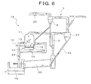
- a raw material heated by heat exchange with hot gas in a suspension preheater 7 is discharged from a lower-stage cyclone 8 of the suspension preheater 7, and a portion of the raw material is dispersively loaded into a rotary kiln exhaust gas duct 9, with the remaining portion of the raw material supplied to a raw material supply chute 12 of a fluidized calciner 11 as depicted in Figure 6 .
- high-pressure air is blown in through a fluidization air blowing port 13, an air chamber 13a, and an air dispersing plate 14 to form a fluidizing bed 15.
- the high-pressure air causes combustion of a portion of fuel supplied through a pulverized supply pipe 16, makes a calcination target raw material stagnant in the fluidizing bed 15 for a predetermined time, and then causes the raw material to fly up to a free board 17 located above the fluidizing bed 15.
- air from a hot clinker cooler 18 is sucked through a suction port 19 substantially in a tangential direction, and the fuel supplied through the pulverized coal supply pipe 16 is also combusted in the free board 17.
- the raw material loaded through the upper raw material supply chute 12 and the raw material flying up from a surface of the fluidizing bed 15 are efficiently and quickly calcined.
- calcined raw material is entrained by calciner exhaust gas and enters a separating cyclone 21.
- the raw material dispersively loaded into the rotary kiln exhaust gas duct 9 is also partly calcined by rotary kiln exhaust gas and enters the separating cyclone 21 along with the rotary kiln exhaust gas.
- a calcination raw material collected by the separating cyclone 21 is introduced into a rotary kiln 20 via a raw material chute 22.
- a solid fuel such as coal is generally used as fuel that allows a cement raw material to be calcined.
- bituminous coal which has high combustion quality, is micronized to fine powder for use.
- various types of fuel such as coal and oil coke, which have low combustion quality.
- Patent Literature 1 described below proposes a fluidized calciner for a cement raw material including: a tubular furnace body in which the axial direction of the tube is an up-down direction; an air dispersing plate provided substantially horizontally at a bottom portion of the furnace body and an air chamber below the air dispersing plate; a raw material supply chute located above the air dispersing plate and through which a raw material is supplied; a fuel supply nozzle located above the air dispersing plate and through which solid fuel is supplied to a fluidizing bed; a secondary air duct through which secondary air (extracted air) is supplied to above the air dispersing plate, in which the fuel supply nozzle is connected to the furnace body at a descending slope of 20° or more to a horizontal plane so as to be deflected toward a tangential side with respect to a centripetal direction.
- This conventional fluidized calciner for a cement raw material calcines a raw material by combusting fuel.
- the connection position of the fuel supply nozzle and the like are based on empirical values, and this technique fails to take into account, for example, the presence or absence of the distribution of a raw material concentration or a gas concentration (particularly O 2 ) in the fluidized calciner.
- pulverized coal of coal or coke which has low combustion quality, is used as fuel, there are disadvantages that sufficient calcination fails to be achieved and ducts may be occluded to hinder operation.
- Patent Literature 1 Japanese Patent Laid-Open No. H8-231254
- An object of the present invention is to provide a fluidized calciner that allows a reduction in the rate of unburned fuel at an outlet of a fluidized calciner to enable sufficient calcination while preventing possible occlusion in a preheater, even when pulverized coal of coal or coke, which has low combustion quality, is used as fuel.
- the invention recited in claim 1 provides a fluidized calciner, comprising a tubular furnace body in which an axial direction is an up-down direction, a pulverized coal blowing line through which fuel is blown into the furnace body, a raw material chute through which a cement raw material is loaded into the furnace body, at least one air introduction pipe through which introduced air is sucked, the pulverized coal blowing line, the raw material chute, and the air introduction pipe being connected to a side portion of the furnace body, and a fluidizing air blowing port disposed at a bottom portion of the furnace body and through which fluidizing air is blown into the furnace body, wherein a blowing port of the pulverized coal blowing line is disposed below a suction port of the air introduction pipe and above the fluidizing air blowing port.
- the invention recited in claim 2 provides the invention recited in claim 1, wherein a center of the blowing port of the pulverized coal blowing line is disposed at a position 200 mm away from the fluidizing air blowing port and at a position of 35 to 145° from a center of a loading port of the raw material chute with respect to a circumferential direction of the furnace body.
- the invention recited in claim 3 provides the invention recited in claim 1, wherein a center of the blowing port of the pulverized coal blowing line is disposed at a position at least 350 mm away from the fluidizing air blowing port and at a position of 90 to 145° from a center of a loading port of the raw material chute with respect to a circumferential direction of the furnace body.
- the invention recited in claim 4 provides the invention recited in claim 1, wherein a center of the blowing port of the pulverized coal blowing line is disposed at a position at least 200 mm away from the fluidizing air blowing port and at a position of 100 to 120° from a center of a loading port of the raw material chute with respect to a circumferential direction of the furnace body.
- the blowing port of the pulverized coal blowing line connected to the side portion of the tubular furnace body in which the axial direction is the up-down direction is disposed below the suction port of the air introduction pipe connected to the side portion of the furnace body and above the fluidizing air blowing port disposed at the bottom portion of the furnace body.
- the center of the blowing port of the pulverized coal blowing line is disposed at a position 200 mm away from the fluidizing air blowing port and at a position of 35 to 145° from the center of the loading port of the raw material chute with respect to the circumferential direction of the furnace body.
- a mean char reaction rate can be set to at least 60%
- a mean raw material decarbonation rate can be set to at least 50%.
- the center of the blowing port of the pulverized coal blowing line is disposed at a position at least 350 mm away from the fluidizing air blowing port and at a position of 90 to 145° from the center of the loading port of the raw material chute with respect to the circumferential direction of the furnace body.
- the mean char reaction rate can be set to at least 60%
- the mean raw material decarbonation rate can be set to at least 50%.
- the center of the blowing port of the pulverized coal blowing line is disposed at a position at least 200 mm away from the fluidizing air blowing port and at a position of 100 to 120° from the center of the loading port of the raw material chute with respect to the circumferential direction of the furnace body.
- Embodiment 1 of a fluidized calciner 1 of the present invention is roughly configured to include a tubular furnace body 2 in which an axial direction is an up-down direction, a pulverized coal blowing line 3 through which pulverized coal as fuel is blown into the furnace body 2, a raw material chute 4 through which a cement raw material is loaded into the furnace body 2, a plurality of (in the drawings, four) air introduction pipe 5 through which introduced air is sucked, the pulverized coal blowing line 3, the raw material chute 4, and the air introduction pipe 5 being connected to a side portion of the furnace body 2, and a fluidizing air blowing port 6 disposed at a bottom portion of the furnace body 2 and through which fluidizing air is blown into the furnace body.
- the furnace body 2 has an inner diameter of 4 to 6 m.
- the four air introduction pipe 5 are connected to the side portion of the furnace body 2 at a descending slope so that the centers of suction ports of the air introduction pipe 5 are disposed on the same circumference.
- the angle between the center line of the air introduction pipe 5 and a horizontal plane is set between 55 and 65°.
- a gas velocity in the air introduction pipe 5 is set to approximately 15 to 18 m/s.
- the center of the suction port of the air introduction pipe 5 is disposed at a height dimension of 1,500 to 2,500 mm above the fluidizing air blowing port 6.
- a plurality of (normally four as depicted in the drawings) air introduction pipes 5 are disposed at approximately equal intervals in a circumferential direction.
- the raw material chute 4 is connected to the furnace body 2 between the air introduction pipes 5 at a descending slope, and the angle between the raw material chute 4 and a horizontal plane is empirically determined based on the coefficient of friction and the angle of repose for raw material particles. For normal cement raw materials, the angle between the raw material chute 4 and the horizontal plane is set to approximately 50° to 70°. Furthermore, the diameter of the raw material chute 4 is designed to be suitable for the amount of raw material loaded. Thus, the center of a loading port of the raw material chute 4 is arranged at a height dimension within the range of approximately 1,500 to 3,000 mm above the fluidizing air blowing port 6, though the height dimension depends on the production capacity of the fluidized calciner.
- the fluidizing air blowing port 6 allows high-pressure air to be blown into the furnace body 2 through an air chamber 13a and an air dispersing plate 14, for example, as depicted in the conventional example in Figure 6 .
- the air dispersing plate 14 is disposed parallel to a radial direction of the furnace body 2, as the fluidizing air blowing port 6.
- the blowing velocity of fluidizing air through the fluidizing air blowing port 6 is determined depending on a raw material density and a particle size distribution and is set to 1.0 to 2.0 m/s for normal cement raw materials.
- the pulverized coal blowing line 3 through which pulverized coal as fuel, for example, coal or coke, is blown into the furnace body 2, is connected to the furnace body 2 below any one of the four air introduction pipes 5 and above the fluidizing air blowing port 6. Furthermore, the pulverized coal blowing line 3 is connected to the furnace body 2 perpendicularly to a shaft center line thereof so as to extend toward the center of the furnace body 2. Additionally, the center of the blowing port of the pulverized coal blowing line 3 is disposed in alignment with the center of the air introduction pipe 5 with respect to the vertical direction. In addition, a carrying air velocity in the pulverized coal blowing line is an adjustment item for operation. The range of the speed is normally set between 10 and 20 m/s.
- the height of the blowing port of the pulverized coal blowing line 3 from the fluidizing air blowing port 6 depends on the position of the raw material chute 4. For example, when the center of the blowing port of the pulverized coal blowing line 3 and the center of the loading port of the raw material chute 4 are disposed at positions within the range of 35 to 145° with respect to the circumferential direction of the furnace body 2, the blowing port is arranged at a height dimension of 200 mm.
- the blowing port of the pulverized coal blowing line 3 and the center of the loading port of the raw material chute 4 are disposed at positions within the range of 90 to 145° with respect to the circumferential direction of the furnace body 2, the blowing port is arranged at a height dimension of at least 350 mm.
- the fluidized calciner 1 with the above-described configuration has been configured based on the results of calculations executed by the inventors based on computational fluid dynamics (CFD); through the calculations, the inventors have found that a flow of pulverized coal blown in through the pulverized coal blowing line 3 is impacted by a flow of a raw material loaded through the raw material chute 4 and a flow of gas through the air introduction pipe 5, and found the height of the blowing port of the pulverized coal blowing line 3 from the fluidizing air blowing port 6 and a suitable positional relation between the pulverized coal blowing line 3 and the raw material chute 4 in the circumferential direction of the furnace body 2 as illustrated in Example 1 and Example 2 described below.
- CFD computational fluid dynamics
- the introduced air makes the same impact on a flow of pulverized coal regardless of whether the bleed air is blown or sucked through the air introduction pipe 5.
- the calculations in accordance with the computational fluid dynamics involve quantifying the actual shape of the fluidized calciner and operational conditions therefor and numerically calculating gas flow, particle migration, chemical reaction, and heat transfer using a computer in which an analysis program is installed, to make determination of the state of combustion and calcination in the fluidized calciner using computer graphics, the determination being otherwise difficult to make based on actual measurements.
- (2) to (13) are all general-purpose models widely used by those skilled in the art; (2) to (11) are used to perform numerical fluid analysis on a flow of gas or the like, (12) is used to perform combustion analysis, and (13) is used to analyze decarbonation of limestone.
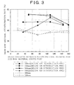
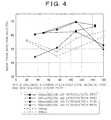
- Evaluation using the calculations in accordance with the computational fluid dynamics is performed by calculating the mean raw material decarbonation rate (%) with respect to the angles of the blowing port of the pulverized coal blowing line 3 and the loading port of the raw material chute 4 for a plurality of cases for the position of the pulverized coal blowing line 3 and a pulverized coal blowing height (h) of the pulverized coal blowing line 3, as depicted in Figure 3 , and similarly calculating the mean char reaction rate (%) with respect to the angle between the blowing port of the pulverized coal blowing line 3 and the loading port of the raw material chute 4 for a plurality of cases for the position of the pulverized coal blowing line 3 and the pulverized coal blowing height (h) of the pulverized coal blowing line 3, as depicted in Figure 4 .
- the mean raw material decarbonation rate (%) has been obtained by performing weighted averaging on the decarbonation rate for each raw material particle at the outlet of the calciner in accordance with the weight of the particle that has not been calcined.
- the mean char reaction rate (%) has been obtained by performing weighted averaging on the char reaction rate for each pulverized coal particle at the outlet of the calciner in accordance with the weight of char that has not reacted.
- the mean raw material decarbonation rate (%) of at least 50% is evaluated to correspond to high relevant performance.
- a mean char reaction rate (%) of at least 60% is evaluated to correspond to high relevant performance.
- the graph of the mean raw material decarbonation rate (%) in Figure 3 and the graph of the mean char reaction rate (%) in Figure 4 are related to Example 1 where each pulverized coal blowing line 3 is connected to the furnace body below the corresponding air introduction pipe 5 and where the center of the blowing port of the pulverized coal blowing line 3 is positioned at a height dimension of 200 mm from the fluidizing air blowing port 6,
- Example 2 where the center of the blowing port of the pulverized coal blowing line 3 is positioned at a height dimension of at least 350 mm (350 mm, 500 mm, and 850 mm) from the fluidizing air blowing port
- Comparative Example where each pulverized coal blowing line 3 is connected to the furnace body at a position other than the position below the corresponding air introduction pipe 5 and where the center of the blowing port of the pulverized coal blowing line 3 is positioned at height dimensions of 200 mm and 350 mm from the fluidizing air blowing port 6.
- Example 1 The composition of coal used in Example 1, Example 2, and Comparative Example illustrated below is as follows.
- the raw material chute 4 was arranged at a position (in the drawings, 75°) closer to the pulverized coal blowing line 3 connected to the furnace body below the air introduction pipe 5, based on the shape of the actual furnace, as depicted in Figure 1 and Figure 2A .
- the center of the loading port of the raw material chute 4 was arranged at a height dimension of 2,000 mm above the fluidizing air blowing port 6 and in alignment with the center of the suction port of the air introduction pipe 5 arranged in alignment with the fluidizing air blowing port 6 in the circumferential direction.
- the angle between the blowing port of the pulverized coal blowing line 3 and the loading port of the raw material chute 4 is as follows.
- Example 1 where the pulverized coal blowing line 3 was arranged below the air introduction pipe 5 and at a height dimension of 200 mm from the fluidizing air blowing port 6, it has been found that the mean raw material decarbonation rate (%) in Figure 3 and the mean char reaction rate (%) in Figure 4 are set to at least 50% and at least 60%, respectively, by arranging the pulverized coal blowing line 3 and the raw material chute 4 such that the angle between the blowing port of the pulverized coal blowing line 3 and the loading port of the raw material chute 4 is within the range of 35 to 145°.
- Example 2 like in Example 1, the raw material chute 4 was arranged at a position (in the drawings, 110°) further from the pulverized coal blowing line 3 connected to the furnace body below the air introduction pipe 5, based on the shape of the actual furnace, as depicted in Figure 1 and Figure 2B .
- the center of the loading port of the raw material chute 4 was arranged at a height dimension of 2,000 mm above the fluidizing air blowing port 6 and in alignment with the center of the blowing port of the air introduction pipe 5 arranged in alignment with the fluidizing air blowing port 6 in the circumferential direction.
- the angle between the blowing port of the pulverized coal blowing line 3 and the loading port of the raw material chute 4 for each height of the blowing port of the pulverized coal blowing line 3 is as follows.
- Example 2 where the pulverized coal blowing line 3 was arranged below the air introduction pipe 5 and at a height dimension of at least 350 mm from the fluidizing air blowing port 6, it has been found that the mean raw material decarbonation rate (%) in Figure 3 and the mean char reaction rate (%) in Figure 4 are set to at least 50% and at least 60%, respectively, by arranging the pulverized coal blowing line 3 and the raw material chute 4 such that the angle between the blowing port of the pulverized coal blowing line 3 and the loading port of the raw material chute 4 is within the range of 90 to 145°.
- the mean raw material decarbonation rate (%) is high and at least 50% but the gas temperature near the furnace wall in the furnace body 2 is high at a height position of 5 to 20 m when the pulverized coal blowing line 3 is attached closer to the raw material chute 4 below the air introduction pipe 5. This may cause burnout of bricks in the furnace body 2.
- the raw material chute 4 was arranged at a position (in the drawings, 75°) closer to the pulverized coal blowing line 3 connected to the furnace body at a position other than the position below the air introduction pipe 5, based on the shape of the actual furnace, as depicted in Figure 2C .
- the center of the loading port of the raw material chute 4 was arranged at a height dimension of 2,000 mm above the fluidizing air blowing port 6 and in alignment with the center of the blowing port of the air introduction pipe 5 arranged in alignment with the fluidizing air blowing port 6 in the circumferential direction.
- the angle between the blowing port of the pulverized coal blowing line 3 and the loading port of the raw material chute 4 for each height of the blowing port of the pulverized coal blowing line 3 is as follows.
- the results of the calculations in accordance with the computational fluid dynamics first indicate that, when the blowing port of the pulverized coal blowing line 3 is arranged below the air introduction pipe 5, the gas temperature at the bottom portion of the furnace body 2 is higher than when the blowing port of the pulverized coal blowing line 3 is not arranged below the air introduction pipe 5, as depicted in Figure 5 . This indicates that, when the blowing port of the pulverized coal blowing line 3 is arranged below the air introduction pipe 5, the pulverized coal is ignited quickly, leading to improved combustion quality.
- a supply position for pulverized coal can be optimized by arranging the pulverized coal blowing line 3 at a height of at least 200 mm from the fluidizing air blowing port 6.
- the pulverized coal blowing line 3 when the pulverized coal blowing line 3 is attached at a position close to the raw material chute 4 below the suction port of the air introduction pipe 5, at a height of 350 mm from the fluidizing air blowing port 6, the flow of pulverized coal is strongly impacted by the flow of the raw material and is displaced from an area with a low raw material concentration and a high O 2 concentration, leading to a low char reaction rate.
- the pulverized coal blowing line 3 when the pulverized coal blowing line 3 was arranged at a height of 200 mm from the fluidizing air blowing port 6, the impact of the flow of the raw material was reduced to allow the pulverized coal to be blown into the desired area, enabling the supply position for pulverized coal to be optimized.
- the blowing port of the pulverized coal blowing line 3 connected to the side portion of the tubular furnace body 2 in which the axial direction is the up-down direction is arranged below the suction port of the air introduction pipe 5 connected to the side portion of the furnace body 2 and above the fluidizing air blowing port 6 disposed at the bottom portion of the furnace body 2.
- the flow of fuel is strongly impacted by the flow of introduced air, allowing the fuel to be blown into the area with a low raw material concentration (which reduces the likelihood of heat absorption as a result of decarbonation) and a high O 2 concentration. Consequently, combustion can be improved.
- a mean char reaction rate can be set to at least 60%, and a mean raw material decarbonation rate can be set to at least 50%.
- the mean char reaction rate can be set to at least 60%, and the mean raw material decarbonation rate can be set to at least 50%. Even when pulverized coal of coal or coke, which has low combustion quality, is used as fuel, the rate of unburned fuel at the outlet of furnace body located at the upper portion thereof can be reduced to keep the temperature in the preheater low, preventing possible occlusion due to the generation of attachment in the cyclone or the raw material chute. Furthermore, wear on refractories can be reduced.
- the center of the blowing port of the pulverized coal blowing line 3 is disposed at a position at least 200 mm away from the fluidizing air blowing port 6 and at a position of 100 to 120° from the center of the loading port of the raw material chute 4 with respect to the circumferential direction of the furnace body 2.
- the rate of unburned fuel at the outlet of furnace body 2 located at the upper portion thereof can be reduced to keep the temperature in the preheater low, preventing possible occlusion due to the generation of attachment in the cyclone or the raw material chute.
- wear on refractories can be reduced.
- the present invention can be utilized for a tubular fluidized calciner in which the axial direction is the up-down direction.
Landscapes
- Engineering & Computer Science (AREA)
- Chemical & Material Sciences (AREA)
- Ceramic Engineering (AREA)
- Mechanical Engineering (AREA)
- General Engineering & Computer Science (AREA)
- Dispersion Chemistry (AREA)
- Thermal Sciences (AREA)
- Physics & Mathematics (AREA)
- Materials Engineering (AREA)
- Structural Engineering (AREA)
- Organic Chemistry (AREA)
- Crucibles And Fluidized-Bed Furnaces (AREA)
- Combustion & Propulsion (AREA)
- Furnace Details (AREA)
- Solid Fuels And Fuel-Associated Substances (AREA)
Abstract
Description
- The present invention relates to a fluidized calciner that enables the rate of unburned fuel at an outlet of a calciner to be reduced by optimizing a supply position for pulverized coal.
- Conventionally, in a
cement manufacturing facility 10 with a fluidized calciner, a raw material heated by heat exchange with hot gas in asuspension preheater 7 is discharged from a lower-stage cyclone 8 of thesuspension preheater 7, and a portion of the raw material is dispersively loaded into a rotary kiln exhaust gas duct 9, with the remaining portion of the raw material supplied to a rawmaterial supply chute 12 of afluidized calciner 11 as depicted inFigure 6 . - In the fluidized
calciner 11, high-pressure air is blown in through a fluidizationair blowing port 13, an air chamber 13a, and anair dispersing plate 14 to form a fluidizing bed 15. At this time, the high-pressure air causes combustion of a portion of fuel supplied through a pulverizedsupply pipe 16, makes a calcination target raw material stagnant in the fluidizing bed 15 for a predetermined time, and then causes the raw material to fly up to a free board 17 located above the fluidizing bed 15. Furthermore, air from ahot clinker cooler 18 is sucked through asuction port 19 substantially in a tangential direction, and the fuel supplied through the pulverizedcoal supply pipe 16 is also combusted in the free board 17. Thus, the raw material loaded through the upper rawmaterial supply chute 12 and the raw material flying up from a surface of the fluidizing bed 15 are efficiently and quickly calcined. - Then, all of the calcined raw material is entrained by calciner exhaust gas and enters a separating
cyclone 21. On the other hand, the raw material dispersively loaded into the rotary kiln exhaust gas duct 9 is also partly calcined by rotary kiln exhaust gas and enters the separatingcyclone 21 along with the rotary kiln exhaust gas. Moreover, a calcination raw material collected by the separatingcyclone 21 is introduced into arotary kiln 20 via araw material chute 22. - On the other hand, hot air generated in the
clinker cooler 18 is sucked into therotary kiln 20 and the fluidizedcalciner 11 by a suction force of aninduction fan 23. However, an excessive amount of hot air is sucked into therotary kiln 20, which offers a low draft resistance. Thus, a part of the rotary kiln exhaust gas duct 9 is reduced in cross-sectional area, and the amount of hot air sucked into the fluidizedcalciner 11 is adjusted by using adamper 24. - In the fluidized calciner, a solid fuel such as coal is generally used as fuel that allows a cement raw material to be calcined. In particular, bituminous coal, which has high combustion quality, is micronized to fine powder for use. However, for effective utilization of limited resources, there has been a demand for the use of various types of fuel such as coal and oil coke, which have low combustion quality.
- However, when pulverized coal of coal or coke, which has low combustion quality, is used as fuel, the rate of unburned fuel at an outlet of the fluidized calciner is high, and combustion occurs in the suspension preheater. As a result, the temperature in the preheater is elevated, and attachment is generated in the cyclone or the raw material chute. Thus, disadvantageously, occlusion frequently occurs in the preheater, hindering operation. Furthermore, in the fluidized calciner, the temperature and the concentration of dust are very high, making determination of a combustion state difficult.
- Thus,
Patent Literature 1 described below proposes a fluidized calciner for a cement raw material including: a tubular furnace body in which the axial direction of the tube is an up-down direction; an air dispersing plate provided substantially horizontally at a bottom portion of the furnace body and an air chamber below the air dispersing plate; a raw material supply chute located above the air dispersing plate and through which a raw material is supplied; a fuel supply nozzle located above the air dispersing plate and through which solid fuel is supplied to a fluidizing bed; a secondary air duct through which secondary air (extracted air) is supplied to above the air dispersing plate, in which the fuel supply nozzle is connected to the furnace body at a descending slope of 20° or more to a horizontal plane so as to be deflected toward a tangential side with respect to a centripetal direction. - This conventional fluidized calciner for a cement raw material calcines a raw material by combusting fuel. However, the connection position of the fuel supply nozzle and the like are based on empirical values, and this technique fails to take into account, for example, the presence or absence of the distribution of a raw material concentration or a gas concentration (particularly O2) in the fluidized calciner. Thus, when pulverized coal of coal or coke, which has low combustion quality, is used as fuel, there are disadvantages that sufficient calcination fails to be achieved and ducts may be occluded to hinder operation.
- Furthermore, for refractories such as a furnace body, excessively high combustion quality disadvantageously causes the temperature near a furnace wall to be locally excessively elevated, leading to a high possibility of burnout.
- Patent Literature 1: Japanese Patent Laid-Open No.
H8-231254 - The present invention has been developed in view of these circumstances. An object of the present invention is to provide a fluidized calciner that allows a reduction in the rate of unburned fuel at an outlet of a fluidized calciner to enable sufficient calcination while preventing possible occlusion in a preheater, even when pulverized coal of coal or coke, which has low combustion quality, is used as fuel.
- To accomplish the object, the invention recited in
claim 1 provides a fluidized calciner, comprising a tubular furnace body in which an axial direction is an up-down direction, a pulverized coal blowing line through which fuel is blown into the furnace body, a raw material chute through which a cement raw material is loaded into the furnace body, at least one air introduction pipe through which introduced air is sucked, the pulverized coal blowing line, the raw material chute, and the air introduction pipe being connected to a side portion of the furnace body, and a fluidizing air blowing port disposed at a bottom portion of the furnace body and through which fluidizing air is blown into the furnace body, wherein a blowing port of the pulverized coal blowing line is disposed below a suction port of the air introduction pipe and above the fluidizing air blowing port. - Furthermore, the invention recited in
claim 2 provides the invention recited inclaim 1, wherein a center of the blowing port of the pulverized coal blowing line is disposed at a position 200 mm away from the fluidizing air blowing port and at a position of 35 to 145° from a center of a loading port of the raw material chute with respect to a circumferential direction of the furnace body. - The invention recited in
claim 3 provides the invention recited inclaim 1, wherein a center of the blowing port of the pulverized coal blowing line is disposed at a position at least 350 mm away from the fluidizing air blowing port and at a position of 90 to 145° from a center of a loading port of the raw material chute with respect to a circumferential direction of the furnace body. - The invention recited in
claim 4 provides the invention recited inclaim 1, wherein a center of the blowing port of the pulverized coal blowing line is disposed at a position at least 200 mm away from the fluidizing air blowing port and at a position of 100 to 120° from a center of a loading port of the raw material chute with respect to a circumferential direction of the furnace body. - According to the invention recited in
claims 1 to 4, the blowing port of the pulverized coal blowing line connected to the side portion of the tubular furnace body in which the axial direction is the up-down direction is disposed below the suction port of the air introduction pipe connected to the side portion of the furnace body and above the fluidizing air blowing port disposed at the bottom portion of the furnace body. Thus, a flow of fuel is strongly impacted by a flow of introduced air, allowing the fuel to be blown into an area with a low raw material concentration (which reduces the likelihood of heat absorption as a result of decarbonation) and high O2 concentration. Consequently, combustion can be improved. This allows a reduction in the rate of unburned fuel at an outlet of the furnace body located at an upper portion thereof to keep the temperature in a preheater low, preventing occlusion in the preheater as a result of attachment generated in a cyclone or the raw material chute. Therefore, appropriate operation can be achieved. - According to the invention recited in
claim 2, the center of the blowing port of the pulverized coal blowing line is disposed at a position 200 mm away from the fluidizing air blowing port and at a position of 35 to 145° from the center of the loading port of the raw material chute with respect to the circumferential direction of the furnace body. Thus, a mean char reaction rate can be set to at least 60%, and a mean raw material decarbonation rate can be set to at least 50%. Even when pulverized coal of coal or coke, which has low combustion quality, is used as fuel, the rate of unburned fuel at the outlet of furnace body located at the upper portion thereof can be reduced to keep the temperature in the preheater low, preventing possible occlusion. Furthermore, wear on refractories can be reduced. - According to the invention recited in
claim 3, the center of the blowing port of the pulverized coal blowing line is disposed at a position at least 350 mm away from the fluidizing air blowing port and at a position of 90 to 145° from the center of the loading port of the raw material chute with respect to the circumferential direction of the furnace body. Thus, the mean char reaction rate can be set to at least 60%, and the mean raw material decarbonation rate can be set to at least 50%. Even when pulverized coal of coal or coke, which has low combustion quality, is used as fuel, the rate of unburned fuel at the outlet of furnace body located at the upper portion thereof can be reduced to keep the temperature in the preheater low, preventing possible occlusion. Furthermore, wear on refractories can be reduced. - According to the invention recited in
claim 4, the center of the blowing port of the pulverized coal blowing line is disposed at a position at least 200 mm away from the fluidizing air blowing port and at a position of 100 to 120° from the center of the loading port of the raw material chute with respect to the circumferential direction of the furnace body. Thus, even when pulverized coal of coal or coke, which has low combustion quality, is used as fuel, the rate of unburned fuel at the outlet of furnace body located at the upper portion thereof can be reduced to keep the temperature in the preheater low, preventing possible occlusion. Furthermore, wear on refractories can be reduced. -
- [
Figure 1] Figure 1 is a schematic diagram depicting an embodiment of a fluidized calciner according to the present invention. - [
Figure 2A] Figure 2A is a schematic diagram depicting a positional relation between a blowing port of a pulverized coal blowing line and a loading port of a raw material chute in a fluidized calciner of the present invention, in which the blowing port of the pulverized coal blowing line is disposed at a position below a suction port of an air introduction pipe, and the loading port of the raw material chute is disposed at a position of 75° with respect to a circumferential direction. - [
Figure 2B] Figure 2B is a schematic diagram depicting the positional relation between the blowing port of the pulverized coal blowing line and the loading port of the raw material chute in the fluidized calciner of the present invention, in which the blowing port of the pulverized coal blowing line is disposed at a position below the suction port of the air introduction pipe, and the loading port of the raw material chute is disposed at a position of 110° with respect to the circumferential direction. - [
Figure 2C] Figure 2C is a schematic diagram depicting the positional relation between the blowing port of the pulverized coal blowing line and the loading port of the raw material chute in the fluidized calciner of the present invention, in which the blowing port of the pulverized coal blowing line is disposed at a position other than the position below the suction port of the air introduction piper, and the loading port of the raw material chute is disposed at a position of 75° with respect to the circumferential direction. - [
Figure 3] Figure 3 is a line graph depicting the angle between the blowing port of the pulverized coal blowing line and the loading port of the raw material chute with respect to the circumferential direction and a mean raw material decarbonation rate (%) at a pulverized coal blowing height (h) of the pulverizedcoal blowing line 3. - [
Figure 4] Figure 4 is a line graph depicting the angle between the blowing port of the pulverized coal blowing line and the loading port of the raw material chute with respect to the circumferential direction and the mean char reaction rate (%) at a pulverized coal blowing height (h) of the pulverizedcoal blowing line 3. - [
Figure 5] Figure 5 is a computer graphic depicting results for the embodiment of the present invention and a variation in temperature distribution depending on a variation in the position of the blowing port of the pulverized coal blowing line. - [
Figure 6] Figure 6 is a schematic diagram of a conventional cement manufacturing facility. - As depicted in
Figure 1 ,Figure 2A, Figure 2B, and Figure 2C ,Embodiment 1 of a fluidizedcalciner 1 of the present invention is roughly configured to include atubular furnace body 2 in which an axial direction is an up-down direction, a pulverized coal blowingline 3 through which pulverized coal as fuel is blown into thefurnace body 2, araw material chute 4 through which a cement raw material is loaded into thefurnace body 2, a plurality of (in the drawings, four)air introduction pipe 5 through which introduced air is sucked, the pulverized coal blowingline 3, theraw material chute 4, and theair introduction pipe 5 being connected to a side portion of thefurnace body 2, and a fluidizingair blowing port 6 disposed at a bottom portion of thefurnace body 2 and through which fluidizing air is blown into the furnace body. Thefurnace body 2 has an inner diameter of 4 to 6 m. - In this regard, the four
air introduction pipe 5 are connected to the side portion of thefurnace body 2 at a descending slope so that the centers of suction ports of theair introduction pipe 5 are disposed on the same circumference. Specifically, the angle between the center line of theair introduction pipe 5 and a horizontal plane is set between 55 and 65°. Furthermore, a gas velocity in theair introduction pipe 5 is set to approximately 15 to 18 m/s. Moreover, the center of the suction port of theair introduction pipe 5 is disposed at a height dimension of 1,500 to 2,500 mm above the fluidizingair blowing port 6. In order to evenly supply air to the furnace bottom portion, a plurality of (normally four as depicted in the drawings)air introduction pipes 5 are disposed at approximately equal intervals in a circumferential direction. - The
raw material chute 4 is connected to thefurnace body 2 between theair introduction pipes 5 at a descending slope, and the angle between theraw material chute 4 and a horizontal plane is empirically determined based on the coefficient of friction and the angle of repose for raw material particles. For normal cement raw materials, the angle between theraw material chute 4 and the horizontal plane is set to approximately 50° to 70°. Furthermore, the diameter of theraw material chute 4 is designed to be suitable for the amount of raw material loaded. Thus, the center of a loading port of theraw material chute 4 is arranged at a height dimension within the range of approximately 1,500 to 3,000 mm above the fluidizingair blowing port 6, though the height dimension depends on the production capacity of the fluidized calciner. - Furthermore, the fluidizing
air blowing port 6 allows high-pressure air to be blown into thefurnace body 2 through an air chamber 13a and anair dispersing plate 14, for example, as depicted in the conventional example inFigure 6 . In the present embodiment, theair dispersing plate 14 is disposed parallel to a radial direction of thefurnace body 2, as the fluidizingair blowing port 6. In this regard, the blowing velocity of fluidizing air through the fluidizingair blowing port 6 is determined depending on a raw material density and a particle size distribution and is set to 1.0 to 2.0 m/s for normal cement raw materials. - The pulverized
coal blowing line 3, through which pulverized coal as fuel, for example, coal or coke, is blown into thefurnace body 2, is connected to thefurnace body 2 below any one of the fourair introduction pipes 5 and above the fluidizingair blowing port 6. Furthermore, the pulverizedcoal blowing line 3 is connected to thefurnace body 2 perpendicularly to a shaft center line thereof so as to extend toward the center of thefurnace body 2. Additionally, the center of the blowing port of the pulverizedcoal blowing line 3 is disposed in alignment with the center of theair introduction pipe 5 with respect to the vertical direction. In addition, a carrying air velocity in the pulverized coal blowing line is an adjustment item for operation. The range of the speed is normally set between 10 and 20 m/s. - The height of the blowing port of the pulverized
coal blowing line 3 from the fluidizingair blowing port 6 depends on the position of theraw material chute 4. For example, when the center of the blowing port of the pulverizedcoal blowing line 3 and the center of the loading port of theraw material chute 4 are disposed at positions within the range of 35 to 145° with respect to the circumferential direction of thefurnace body 2, the blowing port is arranged at a height dimension of 200 mm. - Furthermore, when the center of the blowing port of the pulverized
coal blowing line 3 and the center of the loading port of theraw material chute 4 are disposed at positions within the range of 90 to 145° with respect to the circumferential direction of thefurnace body 2, the blowing port is arranged at a height dimension of at least 350 mm. - The
fluidized calciner 1 with the above-described configuration has been configured based on the results of calculations executed by the inventors based on computational fluid dynamics (CFD); through the calculations, the inventors have found that a flow of pulverized coal blown in through the pulverizedcoal blowing line 3 is impacted by a flow of a raw material loaded through theraw material chute 4 and a flow of gas through theair introduction pipe 5, and found the height of the blowing port of the pulverizedcoal blowing line 3 from the fluidizingair blowing port 6 and a suitable positional relation between the pulverizedcoal blowing line 3 and theraw material chute 4 in the circumferential direction of thefurnace body 2 as illustrated in Example 1 and Example 2 described below. - The introduced air makes the same impact on a flow of pulverized coal regardless of whether the bleed air is blown or sucked through the
air introduction pipe 5. - The calculations in accordance with the computational fluid dynamics involve quantifying the actual shape of the fluidized calciner and operational conditions therefor and numerically calculating gas flow, particle migration, chemical reaction, and heat transfer using a computer in which an analysis program is installed, to make determination of the state of combustion and calcination in the fluidized calciner using computer graphics, the determination being otherwise difficult to make based on actual measurements.
- Methods and models for the calculations in accordance with the computational fluid dynamics are as follows:
- (1) Numerical fluid dynamics computation software (R-flow Corporation Ltd.)
- (2) Turbulence model: k-ε Model
- (3) Fluid: incompressible ideal gas
- (4) Pressure-speed coupling: SIMPLE
- (5) Discretization scheme: Finite Volume Method
- (6) Momentum: Second Order Upwind
- (7) Turbulent kinetic energy: First Order Upwind
- (8) Turbulent dissipation rate: First Order Upwind
- (9) Energy: Second Order Upwind
- (10) Particle analysis: Discrete Element Method
- (11) Particle fluid interaction: Two Way Coupling
- (12) Pulverized coal combustion: H2 + O2 - H2O, CH4 + O2 - H2O + CO2, CO + O2 - CO2, C + O2 - CO2
- (13) Raw material decarbonation model: CaCO3 - CaO + CO2, unreacted core model
- Of these methods and models, (2) to (13) are all general-purpose models widely used by those skilled in the art; (2) to (11) are used to perform numerical fluid analysis on a flow of gas or the like, (12) is used to perform combustion analysis, and (13) is used to analyze decarbonation of limestone.
- Evaluation using the calculations in accordance with the computational fluid dynamics is performed by calculating the mean raw material decarbonation rate (%) with respect to the angles of the blowing port of the pulverized
coal blowing line 3 and the loading port of theraw material chute 4 for a plurality of cases for the position of the pulverizedcoal blowing line 3 and a pulverized coal blowing height (h) of the pulverizedcoal blowing line 3, as depicted inFigure 3 , and similarly calculating the mean char reaction rate (%) with respect to the angle between the blowing port of the pulverizedcoal blowing line 3 and the loading port of theraw material chute 4 for a plurality of cases for the position of the pulverizedcoal blowing line 3 and the pulverized coal blowing height (h) of the pulverizedcoal blowing line 3, as depicted inFigure 4 . - Furthermore, the mean raw material decarbonation rate (%) has been obtained by performing weighted averaging on the decarbonation rate for each raw material particle at the outlet of the calciner in accordance with the weight of the particle that has not been calcined. The mean char reaction rate (%) has been obtained by performing weighted averaging on the char reaction rate for each pulverized coal particle at the outlet of the calciner in accordance with the weight of char that has not reacted. Moreover, the mean raw material decarbonation rate (%) of at least 50% is evaluated to correspond to high relevant performance. A mean char reaction rate (%) of at least 60% is evaluated to correspond to high relevant performance.
- Moreover, the graph of the mean raw material decarbonation rate (%) in
Figure 3 and the graph of the mean char reaction rate (%) inFigure 4 are related to Example 1 where each pulverizedcoal blowing line 3 is connected to the furnace body below the correspondingair introduction pipe 5 and where the center of the blowing port of the pulverizedcoal blowing line 3 is positioned at a height dimension of 200 mm from the fluidizingair blowing port 6, Example 2 where the center of the blowing port of the pulverizedcoal blowing line 3 is positioned at a height dimension of at least 350 mm (350 mm, 500 mm, and 850 mm) from the fluidizing air blowing port, and Comparative Example where each pulverizedcoal blowing line 3 is connected to the furnace body at a position other than the position below the correspondingair introduction pipe 5 and where the center of the blowing port of the pulverizedcoal blowing line 3 is positioned at height dimensions of 200 mm and 350 mm from the fluidizingair blowing port 6. - The composition of coal used in Example 1, Example 2, and Comparative Example illustrated below is as follows.
- Name: Bituminous coal
- Amount of heat generation (Kcal/Kg): 6700
- Volatile content (%): 34.3
- Fixed carbon (%): 49.4
- Water content (%): 6.8
- Ash content (%): 9.5
- When the type of pulverized coal was changed, not only the above-described industrial analytical values were changed but also the amount of pulverized coal fed was adjusted so as to maintain a constant total amount of heat generated by the pulverized coal loaded into the calciner.
- First, for the calculations in accordance with the computational fluid dynamics in Example 1, the
raw material chute 4 was arranged at a position (in the drawings, 75°) closer to the pulverizedcoal blowing line 3 connected to the furnace body below theair introduction pipe 5, based on the shape of the actual furnace, as depicted inFigure 1 andFigure 2A . At this time, the center of the loading port of theraw material chute 4 was arranged at a height dimension of 2,000 mm above the fluidizingair blowing port 6 and in alignment with the center of the suction port of theair introduction pipe 5 arranged in alignment with the fluidizingair blowing port 6 in the circumferential direction. - Furthermore, the calculations in accordance with the computational fluid dynamics were executed for the arrangement where the center of the blowing port of the pulverized
coal blowing line 3 arranged below theair introduction pipe 5 was arranged at a height dimension of 200 mm from the fluidizingair blowing port 6. - The angle between the blowing port of the pulverized
coal blowing line 3 and the loading port of theraw material chute 4 is as follows. - 200 mm: 35°, 75°, 110°, 145°
- Moreover, for operational conditions for the actual furnace such as the amount of cement raw material loaded, flow velocity, and temperature, the following data was used.
-
Furnace body 2- Furnace inner diameter = 4 m
- Furnace length = 25 m
- Pulverized
coal blowing line 3- Amount of pulverized coal fed = 7.4 t/h
- Carrying air flow velocity = 11 m/s
- Temperature = 50°C
-
Raw material chute 4- Cement raw material: 200 t/h
- Temperature = 740°C
- Carrying air flow velocity = 0.5 m/s
- Air introduction pipe 5 (arranged at four positions in the circumferential direction)
- Introduced air
- Temperature = 880°C
- Flow velocity = 15.8 m/s
- Fluidizing air blowing port
- Fluidizing air
- Temperature = 800°C
- Flow velocity = 1.64 m/s
- Then, the mean raw material decarbonation rate (%) and the mean char reaction rate (%) were computationally determined for each angle between the blowing port of the pulverized
coal blowing line 3 and the loading port of theraw material chute 4. The results are as depicted inFigure 3 andFigure 4 . - For Example 1 where the pulverized
coal blowing line 3 was arranged below theair introduction pipe 5 and at a height dimension of 200 mm from the fluidizingair blowing port 6, it has been found that the mean raw material decarbonation rate (%) inFigure 3 and the mean char reaction rate (%) inFigure 4 are set to at least 50% and at least 60%, respectively, by arranging the pulverizedcoal blowing line 3 and theraw material chute 4 such that the angle between the blowing port of the pulverizedcoal blowing line 3 and the loading port of theraw material chute 4 is within the range of 35 to 145°. - Then, in Example 2, like in Example 1, the
raw material chute 4 was arranged at a position (in the drawings, 110°) further from the pulverizedcoal blowing line 3 connected to the furnace body below theair introduction pipe 5, based on the shape of the actual furnace, as depicted inFigure 1 andFigure 2B . At this time, the center of the loading port of theraw material chute 4 was arranged at a height dimension of 2,000 mm above the fluidizingair blowing port 6 and in alignment with the center of the blowing port of theair introduction pipe 5 arranged in alignment with the fluidizingair blowing port 6 in the circumferential direction. - Furthermore, the calculations in accordance with the computational fluid dynamics were executed for the arrangement where the center of the blowing port of the pulverized
coal blowing line 3 arranged below theair introduction pipe 5 was arranged at least 350 mm above the fluidizingair blowing port 6, in Example 2, at three height dimensions of 350 mm, 500 mm, and 850 mm. - The angle between the blowing port of the pulverized
coal blowing line 3 and the loading port of theraw material chute 4 for each height of the blowing port of the pulverizedcoal blowing line 3 is as follows. - 350 mm: 35°, 75°, 110°, 145°
- 500 mm: 50°, 110°, 160°
- 850 mm: 50°, 110°, 160°
- Moreover, for the operational conditions for the actual furnace such as the amount of cement raw material loaded, the flow velocity, and the temperature, like in Example 1, the following data was used for example.
-
Furnace body 2- Furnace inner diameter = 4 m
- Furnace length = 25 m
- Pulverized
coal blowing line 3- Amount of pulverized coal fed = 7.4 t/h
- Carrying air flow velocity = 11 m/s
- Temperature = 50°C
-
Raw material chute 4- Cement raw material: 200 t/h
- Temperature = 740°C
- Carrying air flow velocity = 0.5 m/s
- Air introduction pipe 5 (arranged at four positions in the circumferential direction)
- Introduced air
- Temperature = 880°C
- Flow velocity = 15.8 m/s
- Fluidizing air blowing port
- Fluidizing air
- Temperature = 800°C
- Flow velocity = 1.64 m/s
- Then, for each height dimension of the blowing port of the pulverized
coal blowing line 3, the mean raw material decarbonation rate (%) and the mean char reaction rate (%) were computationally determined for each angle between the blowing port of the pulverizedcoal blowing line 3 and the loading port of theraw material chute 4. The results are as depicted inFigure 3 andFigure 4 . - For Example 2 where the pulverized
coal blowing line 3 was arranged below theair introduction pipe 5 and at a height dimension of at least 350 mm from the fluidizingair blowing port 6, it has been found that the mean raw material decarbonation rate (%) inFigure 3 and the mean char reaction rate (%) inFigure 4 are set to at least 50% and at least 60%, respectively, by arranging the pulverizedcoal blowing line 3 and theraw material chute 4 such that the angle between the blowing port of the pulverizedcoal blowing line 3 and the loading port of theraw material chute 4 is within the range of 90 to 145°. - It has been found that, when the pulverized
coal blowing line 3 is arranged below theair introduction pipe 5 and at a height dimension of at least 500 mm from the fluidizingair blowing port 6, the mean raw material decarbonation rate (%) is high and at least 50% but the gas temperature near the furnace wall in thefurnace body 2 is high at a height position of 5 to 20 m when the pulverizedcoal blowing line 3 is attached closer to theraw material chute 4 below theair introduction pipe 5. This may cause burnout of bricks in thefurnace body 2. - Moreover, in Comparative Example, like in Examples 1 and 2, the
raw material chute 4 was arranged at a position (in the drawings, 75°) closer to the pulverizedcoal blowing line 3 connected to the furnace body at a position other than the position below theair introduction pipe 5, based on the shape of the actual furnace, as depicted inFigure 2C . At this time, the center of the loading port of theraw material chute 4 was arranged at a height dimension of 2,000 mm above the fluidizingair blowing port 6 and in alignment with the center of the blowing port of theair introduction pipe 5 arranged in alignment with the fluidizingair blowing port 6 in the circumferential direction. - Furthermore, the calculations in accordance with the computational fluid dynamics were executed for the arrangement where the center of the blowing port of the pulverized
coal blowing line 3 arranged at the position other than the position below theair introduction pipe 5 was arranged at each of the two height dimensions of 200 mm and 350 mm from the fluidizingair blowing port 6. - The angle between the blowing port of the pulverized
coal blowing line 3 and the loading port of theraw material chute 4 for each height of the blowing port of the pulverizedcoal blowing line 3 is as follows. - 200 mm: 20°, 75°, 110°, 160°
- 350 mm: 20°, 75°, 110°, 160°
- Moreover, for the operational conditions for the actual furnace such as the amount of cement raw material loaded, the flow velocity, and the temperature, like in Examples 1 and 2, the following data was used for example.
-
Furnace body 2- Furnace inner diameter = 4 m
- Furnace length = 25 m
- Pulverized
coal blowing line 3- Amount of pulverized coal fed = 7.4 t/h
- Carrying air flow velocity = 11 m/s
- Temperature = 50°C
-
Raw material chute 4- Cement raw material: 200 t/h
- Temperature = 740°C
- Carrying air flow velocity = 0.5 m/s
- Air introduction pipe 5 (arranged at four positions in the circumferential direction)
- Introduced air
- Temperature = 880°C
- Flow velocity = 15.8 m/s
- Fluidizing air blowing port
- Fluidizing air
- Temperature = 800°C
- Flow velocity = 1.64 m/s
- Then, for each height dimension of the blowing port of the pulverized
coal blowing line 3, the mean raw material decarbonation rate (%) and the mean char reaction rate (%) were computationally determined for each angle between the blowing port of the pulverizedcoal blowing line 3 and the loading port of theraw material chute 4. The results are as depicted by dashed lines inFigure 3 andFigure 4 . - Thus, in Comparative Example where the pulverized
coal blowing line 3 was arranged at the position other than the position below theair introduction pipe 5 and at height dimensions of 200 mm and 350 mm from the fluidizing air blowing port, for the angle between the blowing port of the pulverizedcoal blowing line 3 and the loading port of theraw material chute 4, an appropriate angle failed to be obtained which contributed to high performance in which the mean raw material decarbonation rate (%) inFigure 3 is at least 50% and in which the mean char reaction rate inFigure 4 is at least 60%. - The results of the calculations in accordance with the computational fluid dynamics first indicate that, when the blowing port of the pulverized
coal blowing line 3 is arranged below theair introduction pipe 5, the gas temperature at the bottom portion of thefurnace body 2 is higher than when the blowing port of the pulverizedcoal blowing line 3 is not arranged below theair introduction pipe 5, as depicted inFigure 5 . This indicates that, when the blowing port of the pulverizedcoal blowing line 3 is arranged below theair introduction pipe 5, the pulverized coal is ignited quickly, leading to improved combustion quality. - Furthermore, as depicted in
Figure 3 andFigure 4 , when the pulverizedcoal blowing line 3 is attached to the furnace body at a position far from theraw material chute 4 below the suction port of theair introduction pipe 5, a supply position for pulverized coal can be optimized by arranging the pulverizedcoal blowing line 3 at a height of at least 200 mm from the fluidizingair blowing port 6. - Moreover, when the pulverized
coal blowing line 3 is attached at a position close to theraw material chute 4 below the suction port of theair introduction pipe 5, at a height of 350 mm from the fluidizingair blowing port 6, the flow of pulverized coal is strongly impacted by the flow of the raw material and is displaced from an area with a low raw material concentration and a high O2 concentration, leading to a low char reaction rate. Thus, it has been found that, when the pulverizedcoal blowing line 3 was arranged at a height of 200 mm from the fluidizingair blowing port 6, the impact of the flow of the raw material was reduced to allow the pulverized coal to be blown into the desired area, enabling the supply position for pulverized coal to be optimized. It has also been found that, when the pulverizedcoal blowing line 3 is arranged at a height of at least 500 mm from the fluidizingair blowing port 6, the flow of pulverized coal can be blown into the desired area but excessive combustion occurs locally, with the result that the temperature near the furnace wall becomes excessively high to increase the possibility of burnout. - Furthermore, it has been found that, when the pulverized
coal blowing line 3 is attached to a position other than the position below theair introduction pipe 5, the flow of pulverized coal is impacted only weakly by the flow of introduced air but strongly by the flow of the raw material, precluding the pulverized coal from being blown into the desired area, with the result that combustion is deteriorated regardless of from where the pulverized coal is blown in. - As seen in the results in Examples 1 and 2, in the fluidized calciner disclosed in the above-described embodiment, the blowing port of the pulverized
coal blowing line 3 connected to the side portion of thetubular furnace body 2 in which the axial direction is the up-down direction is arranged below the suction port of theair introduction pipe 5 connected to the side portion of thefurnace body 2 and above the fluidizingair blowing port 6 disposed at the bottom portion of thefurnace body 2. Thus, the flow of fuel is strongly impacted by the flow of introduced air, allowing the fuel to be blown into the area with a low raw material concentration (which reduces the likelihood of heat absorption as a result of decarbonation) and a high O2 concentration. Consequently, combustion can be improved. This allows a reduction in the rate of unburned fuel at the outlet of thefurnace body 2 located at the upper portion thereof to keep the temperature in a preheater low, preventing occlusion in the preheater as a result of attachment generated in a cyclone or the raw material chute. Therefore, appropriate operation can be achieved. - Furthermore, the center of the blowing port of the pulverized
coal blowing line 3 is disposed at a position 200 mm away from the fluidizingair blowing port 6 and at a position of 35 to 145° from the center of the loading port of theraw material chute 4 with respect to the circumferential direction of thefurnace body 2. Thus, a mean char reaction rate can be set to at least 60%, and a mean raw material decarbonation rate can be set to at least 50%. Even when pulverized coal of coal or coke, which has low combustion quality, is used as fuel, the rate of unburned fuel at the outlet offurnace body 2 located at the upper portion thereof can be reduced to keep the temperature in the preheater low, preventing possible occlusion due to the generation of attachment in the cyclone or the raw material chute. Furthermore, wear on refractories can be reduced. - When the center of the blowing port of the pulverized
coal blowing line 3 is disposed at a position at least 350 mm away from the fluidizingair blowing port 6 and at a position of 90 to 145° from the center of the loading port of theraw material chute 4 with respect to the circumferential direction of thefurnace body 2, the mean char reaction rate can be set to at least 60%, and the mean raw material decarbonation rate can be set to at least 50%. Even when pulverized coal of coal or coke, which has low combustion quality, is used as fuel, the rate of unburned fuel at the outlet of furnace body located at the upper portion thereof can be reduced to keep the temperature in the preheater low, preventing possible occlusion due to the generation of attachment in the cyclone or the raw material chute. Furthermore, wear on refractories can be reduced. - Moreover, when the center of the blowing port of the pulverized
coal blowing line 3 is disposed at a position at least 200 mm away from the fluidizingair blowing port 6 and at a position of 100 to 120° from the center of the loading port of theraw material chute 4 with respect to the circumferential direction of thefurnace body 2. Thus, even when pulverized coal of coal or coke, which has low combustion quality, is used as fuel, the rate of unburned fuel at the outlet offurnace body 2 located at the upper portion thereof can be reduced to keep the temperature in the preheater low, preventing possible occlusion due to the generation of attachment in the cyclone or the raw material chute. Furthermore, wear on refractories can be reduced. - The present invention can be utilized for a tubular fluidized calciner in which the axial direction is the up-down direction.
-
- 1
- Fluidized calciner
- 2
- Furnace body
- 3
- Pulverized coal blowing line
- 4
- Raw material chute
- 5
- Air introduction pipe
- 6
- Fluidizing air blowing port
Claims (4)
- A fluidized calciner comprising a tubular furnace body in which an axial direction thereof is an up-down direction, a pulverized coal blowing line through which fuel is blown into the furnace body, a raw material chute through which a cement raw material is loaded into the furnace body, at least one air introduction pipe through which introduced air is sucked, the pulverized coal blowing line, the raw material chute, and the air introduction pipe being connected to a side portion of the furnace body, and a fluidizing air blowing port disposed at a bottom portion of the furnace body and through which fluidizing air is blown into the furnace body,
wherein a blowing port of the pulverized coal blowing line is disposed below a suction port of the air introduction pipe and above the fluidizing air blowing port. - The fluidized calciner according to claim 1, wherein a center of the blowing port of the pulverized coal blowing line is disposed at a position 200 mm away from the fluidizing air blowing port and at a position of 35 to 145° from a center of a loading port of the raw material chute with respect to a circumferential direction of the furnace body.
- The fluidized calciner according to claim 1, wherein a center of the blowing port of the pulverized coal blowing line is disposed at a position at least 350 mm away from the fluidizing air blowing port and at a position of 90 to 145° from a center of a loading port of the raw material chute with respect to a circumferential direction of the furnace body.
- The fluidized calciner according to claim 1, wherein a center of the blowing port of the pulverized coal blowing line is disposed at a position at least 200 mm away from the fluidizing air blowing port and at a position of 100 to 120° from a center of a loading port of the raw material chute with respect to a circumferential direction of the furnace body.
Applications Claiming Priority (3)
| Application Number | Priority Date | Filing Date | Title |
|---|---|---|---|
| JP2012282646 | 2012-12-26 | ||
| JP2013260301A JP6393981B2 (en) | 2012-12-26 | 2013-12-17 | Fluid calciner |
| PCT/JP2013/007585 WO2014103302A1 (en) | 2012-12-26 | 2013-12-25 | Fluidized calcination furnace |
Publications (2)
| Publication Number | Publication Date |
|---|---|
| EP2939989A1 true EP2939989A1 (en) | 2015-11-04 |
| EP2939989A4 EP2939989A4 (en) | 2016-10-19 |
Family
ID=51020418
Family Applications (1)
| Application Number | Title | Priority Date | Filing Date |
|---|---|---|---|
| EP13867691.1A Withdrawn EP2939989A4 (en) | 2012-12-26 | 2013-12-25 | Fluidized calcination furnace |
Country Status (8)
| Country | Link |
|---|---|
| US (1) | US10280115B2 (en) |
| EP (1) | EP2939989A4 (en) |
| JP (1) | JP6393981B2 (en) |
| KR (1) | KR20150098632A (en) |
| CN (1) | CN104903268B (en) |
| IN (1) | IN2015DN04144A (en) |
| TW (1) | TW201441552A (en) |
| WO (1) | WO2014103302A1 (en) |
Families Citing this family (3)
| Publication number | Priority date | Publication date | Assignee | Title |
|---|---|---|---|---|
| JP6187315B2 (en) * | 2014-02-28 | 2017-08-30 | 三菱マテリアル株式会社 | Fluid calciner |
| JP2018118861A (en) * | 2017-01-23 | 2018-08-02 | 三菱マテリアル株式会社 | Cement manufacturing method |
| JP7077578B2 (en) | 2017-11-07 | 2022-05-31 | 三菱マテリアル株式会社 | Cement clinker manufacturing method and manufacturing equipment |
Family Cites Families (25)
| Publication number | Priority date | Publication date | Assignee | Title |
|---|---|---|---|---|
| DE1542307C3 (en) * | 1965-10-05 | 1974-03-14 | Metallgesellschaft Ag, 6000 Frankfurt | Process for temperature control and increasing the throughput of endothermic processes in a fluidized bed |
| US3925024A (en) * | 1971-09-10 | 1975-12-09 | Borden Inc | Grid burner system |
| DE2324519C3 (en) * | 1973-05-15 | 1982-07-08 | Krupp Polysius Ag, 4720 Beckum | Processes and devices for the heat treatment of fine-grained material |
| GB1463124A (en) * | 1974-06-18 | 1977-02-02 | Smidth & Co As F L | Calcination of pulverous material |
| US4372784A (en) * | 1981-08-21 | 1983-02-08 | Allis-Chalmers Corporation | Method for heat treating pulverous raw material calcining combustor therefor |
| JPS60112651A (en) * | 1983-11-24 | 1985-06-19 | 三菱重工業株式会社 | Calciner for cement raw material and lime raw material |
| JPS62230657A (en) * | 1986-04-01 | 1987-10-09 | 川崎重工業株式会社 | Plant for manufacturing cement clinker |
| CA1285761C (en) | 1986-04-01 | 1991-07-09 | Kawasaki Jukogyo Kabushiki Kaisha | Plant for manufacturing cement clinker |
| HU201230B (en) * | 1987-11-17 | 1990-10-28 | Eszakmagyar Vegyimuevek | Acaricides with synergetic effect and comprising thiophosphoryl glycineamide derivative as active ingredient |
| CN1036751A (en) * | 1989-03-18 | 1989-11-01 | 冯冶威 | Burning clinker of cement boiling decomposition technique and equipment |
| US5044942A (en) * | 1990-01-18 | 1991-09-03 | Gas Research Institute | Cement shaft suspension furnace and process |
| US4975046A (en) * | 1990-01-18 | 1990-12-04 | Gas Research Institute | Cement shaft suspension furnace and process |
| US5944513A (en) * | 1992-12-28 | 1999-08-31 | Kawasaki Jukogyo Kabushiki Kaisha | Apparatus for manufacturing cement clinker |
| JP2618836B2 (en) * | 1994-09-08 | 1997-06-11 | 川崎重工業株式会社 | Method and apparatus for firing cement clinker |
| US5788482A (en) | 1994-09-08 | 1998-08-04 | Kawasaki Jukogyo Kabushiki Kaisha | Sintering method of cement clinkers and sintering apparatus of the same |
| JPH08231254A (en) * | 1995-02-27 | 1996-09-10 | Mitsubishi Materials Corp | Cement raw material fluidized calciner |
| CN1117261C (en) * | 1999-03-04 | 2003-08-06 | 国家建筑材料工业局天津水泥工业设计研究院 | Decomposing furnace adaptable to low volatile coal calcination |
| AU3949601A (en) * | 2000-03-27 | 2001-10-08 | Alstom (Switzerland) Ltd | Method of producing steam and an alternate product in a power plant |
| US7297179B2 (en) | 2002-09-30 | 2007-11-20 | Fujifilm Corporation | Method of producing metal particles, and metal oxide obtained from the particles |
| JP4105517B2 (en) * | 2002-09-30 | 2008-06-25 | 富士フイルム株式会社 | Method for producing metal particles |
| US20070163476A1 (en) * | 2006-01-18 | 2007-07-19 | Comrie Douglas C | Apparatus for delivery of sorbent to a furnace during combustion |
| JP4747317B2 (en) | 2009-11-16 | 2011-08-17 | 三菱マテリアル株式会社 | Mixing calciner |
| WO2011058693A1 (en) | 2009-11-16 | 2011-05-19 | 三菱マテリアル株式会社 | Mixing/calcining furnace |
| CN202543077U (en) * | 2012-03-27 | 2012-11-21 | 安徽海螺建材设计研究院 | System for pre-decomposing cement clinker outside kiln |
| CN202532880U (en) * | 2012-03-27 | 2012-11-14 | 安徽海螺川崎装备制造有限公司 | Environmental protection C-KSV decomposition furnace |
-
2013
- 2013-12-17 JP JP2013260301A patent/JP6393981B2/en active Active
- 2013-12-24 TW TW102147977A patent/TW201441552A/en unknown
- 2013-12-25 KR KR1020157016776A patent/KR20150098632A/en not_active Ceased
- 2013-12-25 IN IN4144DEN2015 patent/IN2015DN04144A/en unknown
- 2013-12-25 US US14/441,353 patent/US10280115B2/en active Active
- 2013-12-25 CN CN201380068540.7A patent/CN104903268B/en not_active Expired - Fee Related
- 2013-12-25 EP EP13867691.1A patent/EP2939989A4/en not_active Withdrawn
- 2013-12-25 WO PCT/JP2013/007585 patent/WO2014103302A1/en not_active Ceased
Also Published As
| Publication number | Publication date |
|---|---|
| JP2014141396A (en) | 2014-08-07 |
| WO2014103302A1 (en) | 2014-07-03 |
| CN104903268A (en) | 2015-09-09 |
| US20150307396A1 (en) | 2015-10-29 |
| JP6393981B2 (en) | 2018-09-26 |
| CN104903268B (en) | 2019-06-18 |
| US10280115B2 (en) | 2019-05-07 |
| IN2015DN04144A (en) | 2015-10-16 |
| KR20150098632A (en) | 2015-08-28 |
| EP2939989A4 (en) | 2016-10-19 |
| TW201441552A (en) | 2014-11-01 |
Similar Documents
| Publication | Publication Date | Title |
|---|---|---|
| Boateng | Rotary kilns: transport phenomena and transport processes | |
| Huang et al. | Prediction of ash deposition on superheater tubes from pulverized coal combustion | |
| CN107750320B (en) | Control method for operation of combustion boiler | |
| US10209006B2 (en) | Fluidized calciner | |
| EP2056022B1 (en) | Low bed pressure drop circulating fluidized bed boiler and the combustion process | |
| US10280115B2 (en) | Fluidized calciner | |
| CN107324826A (en) | High heat conduction wearing composite material | |
| CN102425952A (en) | Material scattering device for efficiently dispersing powdery materials | |
| JP5549213B2 (en) | Furnace wall structure of fluidized bed boiler | |
| Ma et al. | Optimizing calculation of particle size distribution of feeding coal for circulating fluidized bed boiler | |
| JP6642059B2 (en) | Fluid calciner | |
| CN115828634A (en) | Prediction method of easily-worn target area of cyclone separator | |
| Bhad et al. | CFD Modeling of a cement Kiln with multi channel burner for optimization of flame profile | |
| Borsuk et al. | Modification of the inlet to the tertiary air duct in the cement kiln installation | |
| WO2016129523A1 (en) | Fluidized calciner | |
| Andrus | Alstom’s Chemical Looping Combustion Technology for CO2 Capture for New and Retrofit Coal-Fired Power Plants | |
| Klett et al. | Methods to reduce operating costs in circulating fluidized bed calcination | |
| Abbas et al. | Reducing pressure drop in pyro-processing | |
| Boerefijn et al. | Attrition in fluidised beds | |
| JP2020158326A (en) | Operation control method of cement firing device, cement firing device and its operating method | |
| Deng et al. | Design, construction and operation of a particle-driven CSP conveyance loop: attrition, erosion, and thermal performance aspects | |
| CN117968052A (en) | Method for cooperatively regulating and controlling circulation multiplying power and deslagging of biomass circulating fluidized bed | |
| Bertrand | Computational study of an alumina flash calciner | |
| Klett et al. | Outokumpu Technology’s State-of-the-Art CFB Calciners–A Review | |
| KR20140134318A (en) | Cement production device |
Legal Events
| Date | Code | Title | Description |
|---|---|---|---|
| PUAI | Public reference made under article 153(3) epc to a published international application that has entered the european phase |
Free format text: ORIGINAL CODE: 0009012 |
|
| 17P | Request for examination filed |
Effective date: 20150617 |
|
| AK | Designated contracting states |
Kind code of ref document: A1 Designated state(s): AL AT BE BG CH CY CZ DE DK EE ES FI FR GB GR HR HU IE IS IT LI LT LU LV MC MK MT NL NO PL PT RO RS SE SI SK SM TR |
|
| AX | Request for extension of the european patent |
Extension state: BA ME |
|
| DAX | Request for extension of the european patent (deleted) | ||
| A4 | Supplementary search report drawn up and despatched |
Effective date: 20160915 |
|
| RIC1 | Information provided on ipc code assigned before grant |
Ipc: F27B 15/14 20060101ALI20160909BHEP Ipc: C04B 7/45 20060101AFI20160909BHEP |
|
| 17Q | First examination report despatched |
Effective date: 20180305 |
|
| STAA | Information on the status of an ep patent application or granted ep patent |
Free format text: STATUS: THE APPLICATION HAS BEEN WITHDRAWN |
|
| 18W | Application withdrawn |
Effective date: 20180418 |