EP2939976A1 - Method for producing microchannel and microchannel - Google Patents
Method for producing microchannel and microchannel Download PDFInfo
- Publication number
- EP2939976A1 EP2939976A1 EP13867007.0A EP13867007A EP2939976A1 EP 2939976 A1 EP2939976 A1 EP 2939976A1 EP 13867007 A EP13867007 A EP 13867007A EP 2939976 A1 EP2939976 A1 EP 2939976A1
- Authority
- EP
- European Patent Office
- Prior art keywords
- curable resin
- liquid
- channel
- microchannel
- needle body
- Prior art date
- Legal status (The legal status is an assumption and is not a legal conclusion. Google has not performed a legal analysis and makes no representation as to the accuracy of the status listed.)
- Granted
Links
Images


Classifications
-
- B—PERFORMING OPERATIONS; TRANSPORTING
- B81—MICROSTRUCTURAL TECHNOLOGY
- B81C—PROCESSES OR APPARATUS SPECIALLY ADAPTED FOR THE MANUFACTURE OR TREATMENT OF MICROSTRUCTURAL DEVICES OR SYSTEMS
- B81C1/00—Manufacture or treatment of devices or systems in or on a substrate
- B81C1/00015—Manufacture or treatment of devices or systems in or on a substrate for manufacturing microsystems
- B81C1/00023—Manufacture or treatment of devices or systems in or on a substrate for manufacturing microsystems without movable or flexible elements
- B81C1/00055—Grooves
- B81C1/00071—Channels
-
- B—PERFORMING OPERATIONS; TRANSPORTING
- B01—PHYSICAL OR CHEMICAL PROCESSES OR APPARATUS IN GENERAL
- B01J—CHEMICAL OR PHYSICAL PROCESSES, e.g. CATALYSIS OR COLLOID CHEMISTRY; THEIR RELEVANT APPARATUS
- B01J19/00—Chemical, physical or physico-chemical processes in general; Their relevant apparatus
- B01J19/0093—Microreactors, e.g. miniaturised or microfabricated reactors
-
- B—PERFORMING OPERATIONS; TRANSPORTING
- B01—PHYSICAL OR CHEMICAL PROCESSES OR APPARATUS IN GENERAL
- B01L—CHEMICAL OR PHYSICAL LABORATORY APPARATUS FOR GENERAL USE
- B01L3/00—Containers or dishes for laboratory use, e.g. laboratory glassware; Droppers
- B01L3/50—Containers for the purpose of retaining a material to be analysed, e.g. test tubes
- B01L3/502—Containers for the purpose of retaining a material to be analysed, e.g. test tubes with fluid transport, e.g. in multi-compartment structures
- B01L3/5027—Containers for the purpose of retaining a material to be analysed, e.g. test tubes with fluid transport, e.g. in multi-compartment structures by integrated microfluidic structures, i.e. dimensions of channels and chambers are such that surface tension forces are important, e.g. lab-on-a-chip
- B01L3/502707—Containers for the purpose of retaining a material to be analysed, e.g. test tubes with fluid transport, e.g. in multi-compartment structures by integrated microfluidic structures, i.e. dimensions of channels and chambers are such that surface tension forces are important, e.g. lab-on-a-chip characterised by the manufacture of the container or its components
-
- B—PERFORMING OPERATIONS; TRANSPORTING
- B29—WORKING OF PLASTICS; WORKING OF SUBSTANCES IN A PLASTIC STATE IN GENERAL
- B29C—SHAPING OR JOINING OF PLASTICS; SHAPING OF MATERIAL IN A PLASTIC STATE, NOT OTHERWISE PROVIDED FOR; AFTER-TREATMENT OF THE SHAPED PRODUCTS, e.g. REPAIRING
- B29C67/00—Shaping techniques not covered by groups B29C39/00 - B29C65/00, B29C70/00 or B29C73/00
- B29C67/0048—Local deformation of formed objects
-
- B—PERFORMING OPERATIONS; TRANSPORTING
- B81—MICROSTRUCTURAL TECHNOLOGY
- B81B—MICROSTRUCTURAL DEVICES OR SYSTEMS, e.g. MICROMECHANICAL DEVICES
- B81B1/00—Devices without movable or flexible elements, e.g. microcapillary devices
-
- B—PERFORMING OPERATIONS; TRANSPORTING
- B81—MICROSTRUCTURAL TECHNOLOGY
- B81C—PROCESSES OR APPARATUS SPECIALLY ADAPTED FOR THE MANUFACTURE OR TREATMENT OF MICROSTRUCTURAL DEVICES OR SYSTEMS
- B81C1/00—Manufacture or treatment of devices or systems in or on a substrate
-
- C—CHEMISTRY; METALLURGY
- C12—BIOCHEMISTRY; BEER; SPIRITS; WINE; VINEGAR; MICROBIOLOGY; ENZYMOLOGY; MUTATION OR GENETIC ENGINEERING
- C12M—APPARATUS FOR ENZYMOLOGY OR MICROBIOLOGY; APPARATUS FOR CULTURING MICROORGANISMS FOR PRODUCING BIOMASS, FOR GROWING CELLS OR FOR OBTAINING FERMENTATION OR METABOLIC PRODUCTS, i.e. BIOREACTORS OR FERMENTERS
- C12M23/00—Constructional details, e.g. recesses, hinges
- C12M23/02—Form or structure of the vessel
- C12M23/16—Microfluidic devices; Capillary tubes
-
- G—PHYSICS
- G01—MEASURING; TESTING
- G01N—INVESTIGATING OR ANALYSING MATERIALS BY DETERMINING THEIR CHEMICAL OR PHYSICAL PROPERTIES
- G01N37/00—Details not covered by any other group of this subclass
-
- B—PERFORMING OPERATIONS; TRANSPORTING
- B01—PHYSICAL OR CHEMICAL PROCESSES OR APPARATUS IN GENERAL
- B01J—CHEMICAL OR PHYSICAL PROCESSES, e.g. CATALYSIS OR COLLOID CHEMISTRY; THEIR RELEVANT APPARATUS
- B01J2219/00—Chemical, physical or physico-chemical processes in general; Their relevant apparatus
- B01J2219/00781—Aspects relating to microreactors
- B01J2219/00783—Laminate assemblies, i.e. the reactor comprising a stack of plates
-
- B—PERFORMING OPERATIONS; TRANSPORTING
- B01—PHYSICAL OR CHEMICAL PROCESSES OR APPARATUS IN GENERAL
- B01J—CHEMICAL OR PHYSICAL PROCESSES, e.g. CATALYSIS OR COLLOID CHEMISTRY; THEIR RELEVANT APPARATUS
- B01J2219/00—Chemical, physical or physico-chemical processes in general; Their relevant apparatus
- B01J2219/00781—Aspects relating to microreactors
- B01J2219/00819—Materials of construction
- B01J2219/00833—Plastic
-
- B—PERFORMING OPERATIONS; TRANSPORTING
- B01—PHYSICAL OR CHEMICAL PROCESSES OR APPARATUS IN GENERAL
- B01J—CHEMICAL OR PHYSICAL PROCESSES, e.g. CATALYSIS OR COLLOID CHEMISTRY; THEIR RELEVANT APPARATUS
- B01J2219/00—Chemical, physical or physico-chemical processes in general; Their relevant apparatus
- B01J2219/00781—Aspects relating to microreactors
- B01J2219/00851—Additional features
- B01J2219/00858—Aspects relating to the size of the reactor
- B01J2219/0086—Dimensions of the flow channels
-
- B—PERFORMING OPERATIONS; TRANSPORTING
- B01—PHYSICAL OR CHEMICAL PROCESSES OR APPARATUS IN GENERAL
- B01L—CHEMICAL OR PHYSICAL LABORATORY APPARATUS FOR GENERAL USE
- B01L2300/00—Additional constructional details
- B01L2300/12—Specific details about materials
-
- B—PERFORMING OPERATIONS; TRANSPORTING
- B29—WORKING OF PLASTICS; WORKING OF SUBSTANCES IN A PLASTIC STATE IN GENERAL
- B29C—SHAPING OR JOINING OF PLASTICS; SHAPING OF MATERIAL IN A PLASTIC STATE, NOT OTHERWISE PROVIDED FOR; AFTER-TREATMENT OF THE SHAPED PRODUCTS, e.g. REPAIRING
- B29C35/00—Heating, cooling or curing, e.g. crosslinking or vulcanising; Apparatus therefor
- B29C35/02—Heating or curing, e.g. crosslinking or vulcanizing during moulding, e.g. in a mould
- B29C35/08—Heating or curing, e.g. crosslinking or vulcanizing during moulding, e.g. in a mould by wave energy or particle radiation
- B29C35/0805—Heating or curing, e.g. crosslinking or vulcanizing during moulding, e.g. in a mould by wave energy or particle radiation using electromagnetic radiation
- B29C2035/0827—Heating or curing, e.g. crosslinking or vulcanizing during moulding, e.g. in a mould by wave energy or particle radiation using electromagnetic radiation using UV radiation
-
- B—PERFORMING OPERATIONS; TRANSPORTING
- B81—MICROSTRUCTURAL TECHNOLOGY
- B81B—MICROSTRUCTURAL DEVICES OR SYSTEMS, e.g. MICROMECHANICAL DEVICES
- B81B2203/00—Basic microelectromechanical structures
- B81B2203/03—Static structures
- B81B2203/0323—Grooves
- B81B2203/0338—Channels
-
- Y—GENERAL TAGGING OF NEW TECHNOLOGICAL DEVELOPMENTS; GENERAL TAGGING OF CROSS-SECTIONAL TECHNOLOGIES SPANNING OVER SEVERAL SECTIONS OF THE IPC; TECHNICAL SUBJECTS COVERED BY FORMER USPC CROSS-REFERENCE ART COLLECTIONS [XRACs] AND DIGESTS
- Y10—TECHNICAL SUBJECTS COVERED BY FORMER USPC
- Y10T—TECHNICAL SUBJECTS COVERED BY FORMER US CLASSIFICATION
- Y10T428/00—Stock material or miscellaneous articles
- Y10T428/24—Structurally defined web or sheet [e.g., overall dimension, etc.]
- Y10T428/24744—Longitudinal or transverse tubular cavity or cell
Definitions
- the present invention relates to a method for producing a microchannel, and to a microchannel.
- Microfluidic devices in which liquids and the like are allowed to flow through microchannels having diameters of around several ⁇ m to several-hundred ⁇ m to effect biochemical reactions, to perform physicochemical separation manipulations, and the like have been known.
- a channel having a semicircular or circular cross section is needed.
- a method for producing a channel having a semicircular or circular cross section has been proposed.
- Patent Literature 1 describes a method for producing a microchannel device including a pair of half-divided bodies that have long plate shapes and include a groove formed on one face thereof and opened in a semicircular shape in one-end face, in which the half-divided bodies are joined.
- Non Patent Literature 1 describes a method for producing a channel having a circular cross section.
- a dispenser robot for automatically applying an adhesive or the like used when electronic equipment is produced, an ultraviolet-curable resin or the like is directly drawn in a channel pattern shape on a substrate to produce a mold.
- channels having semicircular cross sections are produced by performing molding with PDMS (polydimethylsiloxane) using the produced mold.
- a channel for a circular cross section is produced by affixing the channels with semicircular cross sections to each other.
- Non Patent Literature 2 describes a method for producing a circular PDMS microchannel which is suitable for visualization of micro-flow and simulates microvessels in vivo, such as confocus ⁇ PIV/PTV (Particle Image Velocimetry/Particle Tracking Velocimetry).
- a circular channel is formed by curing PDMS in a state in which a wire is embedded and then pulling the wire out.
- Non Patent Literature 3 describes a method for configuring a microvascular network having a circular cross section from a polystyrene sheet.
- a semicircular master with silicon is configured in an electroplating step and embossed on polystyrene sheets, and the two obtained sheets are joined to form a channel having a circular cross section.
- Patent Literature 1 Japanese Laid-open Patent Publication No. 2012-137325
- a production method in which plural channels with semicircular cross sections are formed and the channels are affixed to each other, includes a number of steps and is complicated. Additionally, since cavities are affixed to each other, it is difficult to form a channel while maintaining a circular shape.
- a circular channel is formed without affixing channels with semicircular cross sections to each other; however, since the method includes the step of pulling the wire out, it is impossible to form a channel without any inlet but it is possible to form only a channel with a simple structure with a straight line shape or the like. Additionally, in the method of Non Patent Literature 2, a step of injecting a liquid into the formed channel is needed for obtaining the channel into which the liquid is injected.
- an objective of the present invention is to provide a method for producing a microchannel including an approximately circular cross section with neither a joined surface nor an inlet in a smaller number of steps than has been conventional.
- a method for producing a microchannel including the steps of forming a layer of an uncured curable resin on a substrate, inserting into the curable resin a needle body that can inject a liquid, injecting a liquid in a tubular shape into the curable resin via the needle body while moving the needle body, extracting the needle body from the curable resin, and curing the curable resin to form a channel in a tubular region injected with the liquid.
- the channel is a channel comprising an approximately circular cross section without any joined surfaces.
- the above method further includes the step of removing a part of the cured curable resin to extract the liquid confined within the curable resin.
- the liquid is a liquid crystal.
- microchannel produced by any one of the above methods is provided.
- the present invention makes it possible to produce a microchannel including an approximately circular cross section with neither a joined surface nor an inlet in a smaller number of steps than has been conventional.
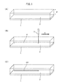
- Figure 1(A) to Figure 1(C) are schematic views for explaining a method for producing a microchannel.
- Figure 2 is a flowchart representing the method for producing a microchannel. Each step in the production method will be explained with reference to Figure 1(A) to Figure 2 .
- a substrate 1 is prepared, and an uncured layer of a curable resin 2 is formed on the substrate 1 (S1). Since the curable resin 2 in an uncured state has flowability, a frame (not illustrated) surrounding a perimeter is prepared, and the curable resin 2 is injected into the frame.
- the curable resin 2 for example, an ultraviolet cured resin such as an acrylic resin or an epoxy resin is used.
- the curable resin 2 may be a thermosetting resin such as a urea resin, a melamine resin, or a phenolic resin.
- the thickness d of the curable resin 2 may be around 1000 ⁇ m.
- a needle (needle body) 3 that can inject a liquid is inserted into the curable resin 2 (S2).
- the needle 3 has a hollow shape tapering down toward a tip thereof, such as the shape of an injection needle, and includes an opening (not illustrated) in the tip.
- a depth to which the needle 3 is inserted is set at, for example, around half of the thickness d of the curable resin 2.
- a needle in which the opening is disposed on a side in the vicinity of a tip of the needle may be used.
- a liquid 4 is injected in a tubular shape into the curable resin 2 via the needle 3 while moving the needle 3 (S3), as illustrated in Figure 1(B) .
- the needle 3 is moved in parallel along an X direction illustrated in Figure 1(B) .
- the liquid 4 is injected from the opening in the tip of the needle 3 into the layer of the curable resin 2 by pressurization from the upper portion of the needle 3 while moving the needle 3.
- the liquid 4 has an approximately circular cross section perpendicular to the X direction due to surface tension.
- liquid 4 examples include liquid crystal.
- liquid crystal is a substance that has flowability such as the flowability of a liquid and includes regular molecular orientation such as the molecular orientation of crystals.
- a liquid may also be used depending on the application of the formed channel.
- the injected liquid 4 may rise to a surface of the resin layer depending on the viscosity of the curable resin 2 or on a difference between the densities of the curable resin 2 and the liquid 4. Therefore, it is necessary to select, as the liquid 4, a liquid that can be injected in a tubular shape into the curable resin 2 depending on the relationship between the viscosity and the density.
- the needle 3 is extracted from the curable resin 2 (S4).
- the curable resin 2 is not yet cured, and therefore, a hole opened in the curable resin 2 by the needle 3 is closed by extracting the needle 3.
- the liquid 4 is confined within the curable resin 2 and placed in the tubular shape.
- the curable resin 2 is cured to confine the liquid 4 within the curable resin 2 to thereby form a portion, in which the liquid 4 is present, as a channel 4A for a liquid (S5).
- an ultraviolet cured resin is used as the curable resin 2
- the curable resin 2 is cured by irradiation with ultraviolet rays.
- a thermosetting resin is used as the curable resin 2
- the curable resin 2 is cured by heating.
- the channel 4A with an approximately circular cross section is formed in a tubular region injected with the liquid 4.
- the liquid 4 may penetrate through the resin layer and the channel 4A may become hollow when the curable resin 2 is cured. A part of the cured curable resin may be removed to extract the liquid 4 confined within the curable resin 2, if a hollow channel is needed when the liquid 4 remains in the channel 4A even after curing the curable resin 2. An as a result, the hollow channel is obtained.
- a channel with an approximately circular cross section is formed without affixing channels with semicircular cross sections to each other. Therefore, in the present production method, a circular channel that does not have any joined surface but has a smooth inner wall can be formed in fewer steps than those of a conventional production method that does not include the present configuration.
- the closed channel without any inlet can be formed since any opening is not present when the channel is formed.
- the liquid 4 injected into the layer of the curable resin 2 has an approximately circular cross section perpendicular to the direction of extension of the liquid 4 due to surface tension.
- the cross section of the finally obtained channel has an approximately circular shape with neither depression nor sharp portion.
- approximately circular shape refers to a shape without any sharp protruding portion, as included in a rectangular shape, in which the rate of a difference between maximum and minimum diameters to the maximum diameter is, for example, 10% or less.
- a circular channel having a structure similar to an actual biological structure is preferred for more accurately reproducing a behavior in an in vivo structure such as, for example, a blood vessel.
- the channel obtained in the present production method can also be utilized in such a bio-related system.
- a channel filled with a liquid When a channel filled with a liquid is needed, it is necessary to inject the liquid into a hollow channel after the channel is formed, in a production method that does not include the present configuration. In contrast, formation of a channel and filling of a liquid are performed in one step since the channel including the liquid therein is formed in the present production method. Therefore, in the present production method, a channel filled with a liquid can be formed in fewer steps than those of a production method that does not include the present configuration.
- an optional liquid can be filled into the formed channel regardless of the viscosity of the curable resin 2 and of a difference between the densities of the curable resin 2 and the liquid 4.
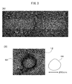
- FIG. 3(A) and Figure 3(B) are photographs representing the experimental results of the production method of Figure 2 .
- Figure 3(A) is a photograph for viewing, from above, the acrylic resins 12 injected (dispensed) with the two P-type liquid crystals 14 described above, respectively.
- Figure 3(B) is a photograph of a cross section of a channel 4A, taken after curing the acrylic resins 12 by irradiation with ultraviolet rays.
- each P-type liquid crystal 14 was dispensed in the form of two straight lines parallel to each other into each acrylic resin 12.
- FIG 4 is a schematic view for explaining the formation location and size of the formed channel 4A illustrated in Figure 3(B) .
- each acrylic resin 12 was formed in a layer shape with a thickness of 1000 ⁇ m, and a needle 3 was inserted to a depth of 500 ⁇ m in each acrylic resin 12.
- a dispensing pressure of 10 kPa was applied while moving the needle 3 at a speed of 20 mm/sec in straight line form along the surface direction of each acrylic resin 12, and each P-type liquid crystal 14 was dispensed so as to have a circular cross section with a diameter of 200 ⁇ m.
- the channel 4A having the cross section as illustrated in Figure 3(B) was obtained by extracting the needle 3 and then curing each acrylic resin 12 with ultraviolet rays.
- Figure 3(B) also illustrates the outline of the cross section of the channel 4A together.
- the difference between the maximum and minimum diameters of the cross section is around 20 ⁇ m, and the rate of the difference between the maximum and minimum diameters to the maximum diameter of the cross section is within around several percent. As described above, it has been confirmed that a channel 4A with an approximately circular cross section is formed by the present production method.
Landscapes
- Chemical & Material Sciences (AREA)
- Engineering & Computer Science (AREA)
- Health & Medical Sciences (AREA)
- Organic Chemistry (AREA)
- Manufacturing & Machinery (AREA)
- Analytical Chemistry (AREA)
- Life Sciences & Earth Sciences (AREA)
- General Health & Medical Sciences (AREA)
- Microelectronics & Electronic Packaging (AREA)
- Zoology (AREA)
- Clinical Laboratory Science (AREA)
- Dispersion Chemistry (AREA)
- Bioinformatics & Cheminformatics (AREA)
- Chemical Kinetics & Catalysis (AREA)
- Wood Science & Technology (AREA)
- Biochemistry (AREA)
- Genetics & Genomics (AREA)
- Biomedical Technology (AREA)
- General Engineering & Computer Science (AREA)
- Microbiology (AREA)
- Biotechnology (AREA)
- Hematology (AREA)
- Sustainable Development (AREA)
- Computer Hardware Design (AREA)
- Mechanical Engineering (AREA)
- Physics & Mathematics (AREA)
- General Physics & Mathematics (AREA)
- Immunology (AREA)
- Pathology (AREA)
- Micromachines (AREA)
- Physical Or Chemical Processes And Apparatus (AREA)
- Apparatus Associated With Microorganisms And Enzymes (AREA)
Abstract
Description
- The present invention relates to a method for producing a microchannel, and to a microchannel.
- Microfluidic devices in which liquids and the like are allowed to flow through microchannels having diameters of around several µm to several-hundred µm to effect biochemical reactions, to perform physicochemical separation manipulations, and the like have been known. In such a microfluidic device, a channel having a semicircular or circular cross section is needed. However, since a channel having a rectangular cross section has been often produced in a photolithography step widely used for producing a microfluidic device, a method for producing a channel having a semicircular or circular cross section has been proposed.
-
Patent Literature 1 describes a method for producing a microchannel device including a pair of half-divided bodies that have long plate shapes and include a groove formed on one face thereof and opened in a semicircular shape in one-end face, in which the half-divided bodies are joined. -
Non Patent Literature 1 describes a method for producing a channel having a circular cross section. In this method, using a dispenser robot for automatically applying an adhesive or the like used when electronic equipment is produced, an ultraviolet-curable resin or the like is directly drawn in a channel pattern shape on a substrate to produce a mold. Then, channels having semicircular cross sections are produced by performing molding with PDMS (polydimethylsiloxane) using the produced mold. In addition, a channel for a circular cross section is produced by affixing the channels with semicircular cross sections to each other. -
Non Patent Literature 2 describes a method for producing a circular PDMS microchannel which is suitable for visualization of micro-flow and simulates microvessels in vivo, such as confocus µPIV/PTV (Particle Image Velocimetry/Particle Tracking Velocimetry). In this method, a circular channel is formed by curing PDMS in a state in which a wire is embedded and then pulling the wire out. -
Non Patent Literature 3 describes a method for configuring a microvascular network having a circular cross section from a polystyrene sheet. In this method, a semicircular master with silicon is configured in an electroplating step and embossed on polystyrene sheets, and the two obtained sheets are joined to form a channel having a circular cross section. - Patent Literature 1: Japanese Laid-open Patent Publication No.
2012-137325 -
- Non Patent Literature 1: "Fabrication of semi-round microchannels using a fluid dispenser and its application to a flow regulator", Teruo Fujii Laboratory, Tokyo University, [online], [searched on December 17, 2012], the Internet <URL: http://www.microfluidics.iis.u-tokyo.ac.jp/r11016_j.html>
- Non Patent Literature 2: Rui Lima et al., "Axisymmetric PDMS microchannels for in vitro haemodynamic studies", Biofbrication, 2009, vol. 1
- Non Patent Literature 3: Jeffery T. Borenstain et al., "Functional endothelialized microvascular networks with circular cross-sections in a tissue culture substrate", Biomed Microdevices, 2010, vol. 12, p. 71-79
- However, a production method, in which plural channels with semicircular cross sections are formed and the channels are affixed to each other, includes a number of steps and is complicated. Additionally, since cavities are affixed to each other, it is difficult to form a channel while maintaining a circular shape.
- In the method of
Non Patent Literature 2, a circular channel is formed without affixing channels with semicircular cross sections to each other; however, since the method includes the step of pulling the wire out, it is impossible to form a channel without any inlet but it is possible to form only a channel with a simple structure with a straight line shape or the like. Additionally, in the method of NonPatent Literature 2, a step of injecting a liquid into the formed channel is needed for obtaining the channel into which the liquid is injected. - Thus, an objective of the present invention is to provide a method for producing a microchannel including an approximately circular cross section with neither a joined surface nor an inlet in a smaller number of steps than has been conventional.
- Provided is a method for producing a microchannel including the steps of forming a layer of an uncured curable resin on a substrate, inserting into the curable resin a needle body that can inject a liquid, injecting a liquid in a tubular shape into the curable resin via the needle body while moving the needle body, extracting the needle body from the curable resin, and curing the curable resin to form a channel in a tubular region injected with the liquid.
- Preferably, in the above method, the channel is a channel comprising an approximately circular cross section without any joined surfaces.
- Preferably, the above method further includes the step of removing a part of the cured curable resin to extract the liquid confined within the curable resin.
- Preferably, in the above method, the liquid is a liquid crystal.
- Additionally, a microchannel produced by any one of the above methods is provided.
- The present invention makes it possible to produce a microchannel including an approximately circular cross section with neither a joined surface nor an inlet in a smaller number of steps than has been conventional.
-
-
Figure 1(A) to (C) are schematic views for explaining a method for producing a microchannel; -
Figure 2 is a flowchart representing the method for producing a microchannel; -
Figure 3(A) and (B) are photographs representing the experimental results of the production method ofFigure 2 ; and -
Figure 4 is a schematic view for explaining the formation location and size of the formed channel illustrated inFigure 3(B) . - Hereinafter, with reference to the drawings, a method for producing a microchannel will be explained in detail. However, it should be noted that the technical scope of the present invention is not limited to embodiments thereof and includes the invention described in claims and equivalents thereof.
-
Figure 1(A) to Figure 1(C) are schematic views for explaining a method for producing a microchannel.Figure 2 is a flowchart representing the method for producing a microchannel. Each step in the production method will be explained with reference toFigure 1(A) to Figure 2 . - First, as illustrated in
Figure 1(A) , asubstrate 1 is prepared, and an uncured layer of acurable resin 2 is formed on the substrate 1 (S1). Since thecurable resin 2 in an uncured state has flowability, a frame (not illustrated) surrounding a perimeter is prepared, and thecurable resin 2 is injected into the frame. As thecurable resin 2, for example, an ultraviolet cured resin such as an acrylic resin or an epoxy resin is used. Alternatively, thecurable resin 2 may be a thermosetting resin such as a urea resin, a melamine resin, or a phenolic resin. When a microchannel with a diameter of around several-hundred µm is formed, the thickness d of thecurable resin 2 may be around 1000 µm. - Subsequently, a needle (needle body) 3 that can inject a liquid is inserted into the curable resin 2 (S2). The
needle 3 has a hollow shape tapering down toward a tip thereof, such as the shape of an injection needle, and includes an opening (not illustrated) in the tip. In this case, a depth to which theneedle 3 is inserted is set at, for example, around half of the thickness d of thecurable resin 2. Alternatively, a needle in which the opening is disposed on a side in the vicinity of a tip of the needle may be used. - Then, a
liquid 4 is injected in a tubular shape into thecurable resin 2 via theneedle 3 while moving the needle 3 (S3), as illustrated inFigure 1(B) . For example, in order to form a channel with a straight line shape, theneedle 3 is moved in parallel along an X direction illustrated inFigure 1(B) . In addition, theliquid 4 is injected from the opening in the tip of theneedle 3 into the layer of thecurable resin 2 by pressurization from the upper portion of theneedle 3 while moving theneedle 3. In the layer of thecurable resin 2, theliquid 4 has an approximately circular cross section perpendicular to the X direction due to surface tension. - Examples of the
liquid 4 include liquid crystal. As used herein, "liquid crystal" is a substance that has flowability such as the flowability of a liquid and includes regular molecular orientation such as the molecular orientation of crystals. In addition, as theliquid 4, a liquid may also be used depending on the application of the formed channel. However, the injectedliquid 4 may rise to a surface of the resin layer depending on the viscosity of thecurable resin 2 or on a difference between the densities of thecurable resin 2 and theliquid 4. Therefore, it is necessary to select, as theliquid 4, a liquid that can be injected in a tubular shape into thecurable resin 2 depending on the relationship between the viscosity and the density. - After the injection of the
liquid 4, theneedle 3 is extracted from the curable resin 2 (S4). In this case, thecurable resin 2 is not yet cured, and therefore, a hole opened in thecurable resin 2 by theneedle 3 is closed by extracting theneedle 3. As a result, theliquid 4 is confined within thecurable resin 2 and placed in the tubular shape. - As illustrated in
Figure 1(C) , thecurable resin 2 is cured to confine theliquid 4 within thecurable resin 2 to thereby form a portion, in which theliquid 4 is present, as achannel 4A for a liquid (S5). When an ultraviolet cured resin is used as thecurable resin 2, thecurable resin 2 is cured by irradiation with ultraviolet rays. When a thermosetting resin is used as thecurable resin 2, thecurable resin 2 is cured by heating. As a result, thechannel 4A with an approximately circular cross section is formed in a tubular region injected with theliquid 4. - Depending on the kind of the
liquid 4, theliquid 4 may penetrate through the resin layer and thechannel 4A may become hollow when thecurable resin 2 is cured. A part of the cured curable resin may be removed to extract theliquid 4 confined within thecurable resin 2, if a hollow channel is needed when the liquid 4 remains in thechannel 4A even after curing thecurable resin 2. An as a result, the hollow channel is obtained. - According to the present production method explained above, a channel with an approximately circular cross section is formed without affixing channels with semicircular cross sections to each other. Therefore, in the present production method, a circular channel that does not have any joined surface but has a smooth inner wall can be formed in fewer steps than those of a conventional production method that does not include the present configuration. In addition, the closed channel without any inlet can be formed since any opening is not present when the channel is formed.
- As described above, the
liquid 4 injected into the layer of thecurable resin 2 has an approximately circular cross section perpendicular to the direction of extension of theliquid 4 due to surface tension. As a result, the cross section of the finally obtained channel has an approximately circular shape with neither depression nor sharp portion. The term "approximately circular shape" mentioned above refers to a shape without any sharp protruding portion, as included in a rectangular shape, in which the rate of a difference between maximum and minimum diameters to the maximum diameter is, for example, 10% or less. - In a bio-related system such as a biosensor or µTAS (Total Analysis System), a circular channel having a structure similar to an actual biological structure is preferred for more accurately reproducing a behavior in an in vivo structure such as, for example, a blood vessel. The channel obtained in the present production method can also be utilized in such a bio-related system.
- When a channel filled with a liquid is needed, it is necessary to inject the liquid into a hollow channel after the channel is formed, in a production method that does not include the present configuration. In contrast, formation of a channel and filling of a liquid are performed in one step since the channel including the liquid therein is formed in the present production method. Therefore, in the present production method, a channel filled with a liquid can be formed in fewer steps than those of a production method that does not include the present configuration.
- Additionally, by allowing the liquid confined within the channel to flow out, a hollow channel can be formed, and another liquid can also be injected after allowing the liquid to flow out. Therefore, an optional liquid can be filled into the formed channel regardless of the viscosity of the
curable resin 2 and of a difference between the densities of thecurable resin 2 and theliquid 4. - An experiment for forming a channel was conducted by the production method of
Figure 2 using acrylic resins as curable resins and using, as liquids to be injected, MLC-7018 and MDA-003461 which were P-type liquid crystals manufactured by Merck.Figure 3(A) and Figure 3(B) are photographs representing the experimental results of the production method ofFigure 2 .Figure 3(A) is a photograph for viewing, from above, theacrylic resins 12 injected (dispensed) with the two P-type liquid crystals 14 described above, respectively.Figure 3(B) is a photograph of a cross section of achannel 4A, taken after curing theacrylic resins 12 by irradiation with ultraviolet rays. In this experiment, each P-type liquid crystal 14 was dispensed in the form of two straight lines parallel to each other into eachacrylic resin 12. -
Figure 4 is a schematic view for explaining the formation location and size of the formedchannel 4A illustrated inFigure 3(B) . In the experiment described above, eachacrylic resin 12 was formed in a layer shape with a thickness of 1000 µm, and aneedle 3 was inserted to a depth of 500 µm in eachacrylic resin 12. In addition, a dispensing pressure of 10 kPa was applied while moving theneedle 3 at a speed of 20 mm/sec in straight line form along the surface direction of eachacrylic resin 12, and each P-type liquid crystal 14 was dispensed so as to have a circular cross section with a diameter of 200 µm. - The
channel 4A having the cross section as illustrated inFigure 3(B) was obtained by extracting theneedle 3 and then curing eachacrylic resin 12 with ultraviolet rays.Figure 3(B) also illustrates the outline of the cross section of thechannel 4A together. The difference between the maximum and minimum diameters of the cross section is around 20 µm, and the rate of the difference between the maximum and minimum diameters to the maximum diameter of the cross section is within around several percent. As described above, it has been confirmed that achannel 4A with an approximately circular cross section is formed by the present production method. -
- 1
- substrate
- 2
- curable resin
- 3
- needle
- 4
- liquid
- 4A
- channel
Claims (5)
- A method for producing a microchannel, comprising the steps of:forming a layer of an uncured curable resin on a substrate;inserting into the curable resin a needle body that can inject a liquid;injecting a liquid in a tubular shape into the curable resin via the needle body while moving the needle body;extracting the needle body from the curable resin; andcuring the curable resin to form a channel in a tubular region injected with the liquid.
- The method according to claim 1, wherein the channel is a channel comprising an approximately circular cross section without any joined surfaces.
- The method according to claim 1 or 2, further comprising the step of removing a part of the cured curable resin to extract the liquid confined within the curable resin.
- The method according to any one of claims 1 to 3, wherein the liquid is a liquid crystal.
- A microchannel produced by the method according to any one of claims 1 to 4.
Applications Claiming Priority (2)
| Application Number | Priority Date | Filing Date | Title |
|---|---|---|---|
| JP2012288628 | 2012-12-28 | ||
| PCT/JP2013/083951 WO2014103842A1 (en) | 2012-12-28 | 2013-12-18 | Method for producing microchannel and microchannel |
Publications (3)
| Publication Number | Publication Date |
|---|---|
| EP2939976A1 true EP2939976A1 (en) | 2015-11-04 |
| EP2939976A4 EP2939976A4 (en) | 2016-10-12 |
| EP2939976B1 EP2939976B1 (en) | 2017-10-18 |
Family
ID=51020929
Family Applications (1)
| Application Number | Title | Priority Date | Filing Date |
|---|---|---|---|
| EP13867007.0A Not-in-force EP2939976B1 (en) | 2012-12-28 | 2013-12-18 | Method for producing microchannel and microchannel |
Country Status (5)
| Country | Link |
|---|---|
| US (1) | US9725307B2 (en) |
| EP (1) | EP2939976B1 (en) |
| JP (1) | JP6138159B2 (en) |
| CN (1) | CN104955768B (en) |
| WO (1) | WO2014103842A1 (en) |
Families Citing this family (5)
| Publication number | Priority date | Publication date | Assignee | Title |
|---|---|---|---|---|
| US8156273B2 (en) * | 2007-05-10 | 2012-04-10 | Freescale Semiconductor, Inc. | Method and system for controlling transmission and execution of commands in an integrated circuit device |
| GB2556270B (en) | 2015-07-27 | 2021-05-12 | Univ Pennsylvania | Lung disease models on a chip |
| USD838864S1 (en) * | 2016-09-07 | 2019-01-22 | EMULATE, Inc. | Opaque microfluidic chip without pressure features for use with a fluid perfusion module |
| CN112155828A (en) * | 2020-10-12 | 2021-01-01 | 吕修波 | Injection molding type fracture and limb fracture fixing device |
| KR102594790B1 (en) * | 2022-01-10 | 2023-10-30 | 동의대학교 산학협력단 | Bubble-assisted fabrication method for manufacturing three-dimensional micro channels of photocurable polymer materials |
Family Cites Families (8)
| Publication number | Priority date | Publication date | Assignee | Title |
|---|---|---|---|---|
| JP2003311697A (en) * | 2002-02-19 | 2003-11-05 | Sumitomo Bakelite Co Ltd | Hollow device, method for producing the same, and reactor having hollow device |
| TWI296711B (en) * | 2005-10-11 | 2008-05-11 | Ind Tech Res Inst | Biochip with microchannels |
| JP4696304B2 (en) * | 2006-02-14 | 2011-06-08 | 独立行政法人産業技術総合研究所 | How to make a mixer |
| CN100528736C (en) * | 2007-11-20 | 2009-08-19 | 东南大学 | Method for manufacturing wafer-level MEMS micro channel |
| US20110033348A1 (en) * | 2008-04-11 | 2011-02-10 | Hiroshi Hirayama | Microchip and Method for Manufacturing Microchip |
| JP2010228174A (en) * | 2009-03-26 | 2010-10-14 | Panasonic Electric Works Co Ltd | Manufacturing method of fine resin structure, fine resin structure manufactured by the manufacturing method, optical waveguide, microlens, microlens array, and microfluidic device |
| JP5565299B2 (en) | 2010-12-24 | 2014-08-06 | 住友ベークライト株式会社 | Manufacturing method of microchannel device |
| JP6038787B2 (en) * | 2011-06-27 | 2016-12-07 | 学校法人慶應義塾 | Manufacturing method of optical waveguide |
-
2013
- 2013-12-18 JP JP2014554362A patent/JP6138159B2/en not_active Expired - Fee Related
- 2013-12-18 EP EP13867007.0A patent/EP2939976B1/en not_active Not-in-force
- 2013-12-18 WO PCT/JP2013/083951 patent/WO2014103842A1/en not_active Ceased
- 2013-12-18 US US14/655,239 patent/US9725307B2/en not_active Expired - Fee Related
- 2013-12-18 CN CN201380068579.9A patent/CN104955768B/en not_active Expired - Fee Related
Also Published As
| Publication number | Publication date |
|---|---|
| JP6138159B2 (en) | 2017-05-31 |
| CN104955768B (en) | 2016-11-09 |
| EP2939976A4 (en) | 2016-10-12 |
| JPWO2014103842A1 (en) | 2017-01-12 |
| EP2939976B1 (en) | 2017-10-18 |
| US20150329354A1 (en) | 2015-11-19 |
| US9725307B2 (en) | 2017-08-08 |
| CN104955768A (en) | 2015-09-30 |
| WO2014103842A1 (en) | 2014-07-03 |
Similar Documents
| Publication | Publication Date | Title |
|---|---|---|
| EP2939976B1 (en) | Method for producing microchannel and microchannel | |
| AU2015311618B2 (en) | Microfluidic devices and fabrication | |
| DE112011104891B4 (en) | 3D microfluidic devices based on openwork thermoplastic elastomer membranes | |
| EP3023151B1 (en) | Method for generating a localised fluid flow circulation zone and corresponding pipette | |
| US10563246B2 (en) | Microfluidic device for production and collection of droplets of a fluid | |
| Azarmanesh et al. | Passive microinjection within high-throughput microfluidics for controlled actuation of droplets and cells | |
| CN108636464B (en) | A molding device and a method for preparing the same | |
| US9404914B2 (en) | Microfluidic system for controlling a concentration profile of molecules capable of stimulating a target | |
| CN101530775B (en) | Micro-fluidic apparatus integrated with PDMS film, manufacturing method and application thereof | |
| CN103285947A (en) | Droplet micro-fluidic chip and operation method thereof | |
| JP2016515214A (en) | High-speed on-demand microfluidic droplet generation and manipulation | |
| CN106215986A (en) | A kind of PDMS microfluidic chip structure and preparation method thereof | |
| Evens et al. | Producing hollow polymer microneedles using laser ablated molds in an injection molding process | |
| CN104998702A (en) | Preparation method of PDMS microfluidic chip based on liquid composite molding method | |
| Rahmanian et al. | Microscale patterning of thermoplastic polymer surfaces by selective solvent swelling | |
| JP6302187B2 (en) | Microchannel chip and manufacturing method thereof | |
| US20140112838A1 (en) | Liquid handling apparatus | |
| CN102033135A (en) | Integrated microfluidic chip interface, interface mould, and interface manufacturing and using methods | |
| US8518481B2 (en) | Interconnect for MEMS device including a viscoelastic septum | |
| JP2010540267A (en) | Mounting method of microfluidic channel | |
| US9162225B2 (en) | Microchip | |
| CN102205602B (en) | Integrated injection molding mold for polymer microfluidic chip substrate and cover sheet | |
| EP2769767A2 (en) | Non-planar moulded article, method for producing the same, its use, method for producing a micro framework and its use | |
| Tanagi et al. | Transparent SU-8 Micronozzle Array with Minimal Dead Volume for Parallel Liquid-to-Liquid Sample Ejection | |
| JP4696304B2 (en) | How to make a mixer |
Legal Events
| Date | Code | Title | Description |
|---|---|---|---|
| PUAI | Public reference made under article 153(3) epc to a published international application that has entered the european phase |
Free format text: ORIGINAL CODE: 0009012 |
|
| 17P | Request for examination filed |
Effective date: 20150616 |
|
| AK | Designated contracting states |
Kind code of ref document: A1 Designated state(s): AL AT BE BG CH CY CZ DE DK EE ES FI FR GB GR HR HU IE IS IT LI LT LU LV MC MK MT NL NO PL PT RO RS SE SI SK SM TR |
|
| AX | Request for extension of the european patent |
Extension state: BA ME |
|
| RIN1 | Information on inventor provided before grant (corrected) |
Inventor name: KATO, SEIKO Inventor name: NOZAKI, TAKAAKI Inventor name: SOMA, KAZUTOMO Inventor name: TAKEISHI, TAKAAKI Inventor name: IDE, MASAFUMI Inventor name: ISHIGURE, TAKAAKI |
|
| DAX | Request for extension of the european patent (deleted) | ||
| RIC1 | Information provided on ipc code assigned before grant |
Ipc: B81B 1/00 20060101ALI20160826BHEP Ipc: B01J 19/00 20060101ALI20160826BHEP Ipc: C12M 1/00 20060101ALI20160826BHEP Ipc: G01N 37/00 20060101ALI20160826BHEP Ipc: B81C 1/00 20060101AFI20160826BHEP |
|
| A4 | Supplementary search report drawn up and despatched |
Effective date: 20160909 |
|
| RIC1 | Information provided on ipc code assigned before grant |
Ipc: B81B 1/00 20060101ALI20160902BHEP Ipc: G01N 37/00 20060101ALI20160902BHEP Ipc: B01J 19/00 20060101ALI20160902BHEP Ipc: B81C 1/00 20060101AFI20160902BHEP Ipc: C12M 1/00 20060101ALI20160902BHEP |
|
| RAP1 | Party data changed (applicant data changed or rights of an application transferred) |
Owner name: KEIO UNIVERSITY Owner name: CITIZEN WATCH CO., LTD. |
|
| GRAP | Despatch of communication of intention to grant a patent |
Free format text: ORIGINAL CODE: EPIDOSNIGR1 |
|
| STAA | Information on the status of an ep patent application or granted ep patent |
Free format text: STATUS: GRANT OF PATENT IS INTENDED |
|
| INTG | Intention to grant announced |
Effective date: 20170509 |
|
| RIN1 | Information on inventor provided before grant (corrected) |
Inventor name: NOZAKI, TAKAAKI Inventor name: KATO, SEIKO Inventor name: TAKEISHI, TAKAAKI Inventor name: IDE, MASAFUMI Inventor name: ISHIGURE, TAKAAKI Inventor name: SOMA, KAZUTOMO |
|
| GRAS | Grant fee paid |
Free format text: ORIGINAL CODE: EPIDOSNIGR3 |
|
| GRAA | (expected) grant |
Free format text: ORIGINAL CODE: 0009210 |
|
| STAA | Information on the status of an ep patent application or granted ep patent |
Free format text: STATUS: THE PATENT HAS BEEN GRANTED |
|
| AK | Designated contracting states |
Kind code of ref document: B1 Designated state(s): AL AT BE BG CH CY CZ DE DK EE ES FI FR GB GR HR HU IE IS IT LI LT LU LV MC MK MT NL NO PL PT RO RS SE SI SK SM TR |
|
| REG | Reference to a national code |
Ref country code: GB Ref legal event code: FG4D |
|
| REG | Reference to a national code |
Ref country code: CH Ref legal event code: EP Ref country code: FR Ref legal event code: PLFP Year of fee payment: 5 |
|
| REG | Reference to a national code |
Ref country code: AT Ref legal event code: REF Ref document number: 937758 Country of ref document: AT Kind code of ref document: T Effective date: 20171115 Ref country code: IE Ref legal event code: FG4D |
|
| REG | Reference to a national code |
Ref country code: DE Ref legal event code: R096 Ref document number: 602013028255 Country of ref document: DE |
|
| REG | Reference to a national code |
Ref country code: NL Ref legal event code: MP Effective date: 20171018 |
|
| REG | Reference to a national code |
Ref country code: LT Ref legal event code: MG4D |
|
| REG | Reference to a national code |
Ref country code: AT Ref legal event code: MK05 Ref document number: 937758 Country of ref document: AT Kind code of ref document: T Effective date: 20171018 |
|
| PG25 | Lapsed in a contracting state [announced via postgrant information from national office to epo] |
Ref country code: NL Free format text: LAPSE BECAUSE OF FAILURE TO SUBMIT A TRANSLATION OF THE DESCRIPTION OR TO PAY THE FEE WITHIN THE PRESCRIBED TIME-LIMIT Effective date: 20171018 |
|
| PG25 | Lapsed in a contracting state [announced via postgrant information from national office to epo] |
Ref country code: NO Free format text: LAPSE BECAUSE OF FAILURE TO SUBMIT A TRANSLATION OF THE DESCRIPTION OR TO PAY THE FEE WITHIN THE PRESCRIBED TIME-LIMIT Effective date: 20180118 Ref country code: LT Free format text: LAPSE BECAUSE OF FAILURE TO SUBMIT A TRANSLATION OF THE DESCRIPTION OR TO PAY THE FEE WITHIN THE PRESCRIBED TIME-LIMIT Effective date: 20171018 Ref country code: SE Free format text: LAPSE BECAUSE OF FAILURE TO SUBMIT A TRANSLATION OF THE DESCRIPTION OR TO PAY THE FEE WITHIN THE PRESCRIBED TIME-LIMIT Effective date: 20171018 Ref country code: ES Free format text: LAPSE BECAUSE OF FAILURE TO SUBMIT A TRANSLATION OF THE DESCRIPTION OR TO PAY THE FEE WITHIN THE PRESCRIBED TIME-LIMIT Effective date: 20171018 Ref country code: FI Free format text: LAPSE BECAUSE OF FAILURE TO SUBMIT A TRANSLATION OF THE DESCRIPTION OR TO PAY THE FEE WITHIN THE PRESCRIBED TIME-LIMIT Effective date: 20171018 |
|
| PG25 | Lapsed in a contracting state [announced via postgrant information from national office to epo] |
Ref country code: LV Free format text: LAPSE BECAUSE OF FAILURE TO SUBMIT A TRANSLATION OF THE DESCRIPTION OR TO PAY THE FEE WITHIN THE PRESCRIBED TIME-LIMIT Effective date: 20171018 Ref country code: BG Free format text: LAPSE BECAUSE OF FAILURE TO SUBMIT A TRANSLATION OF THE DESCRIPTION OR TO PAY THE FEE WITHIN THE PRESCRIBED TIME-LIMIT Effective date: 20180118 Ref country code: GR Free format text: LAPSE BECAUSE OF FAILURE TO SUBMIT A TRANSLATION OF THE DESCRIPTION OR TO PAY THE FEE WITHIN THE PRESCRIBED TIME-LIMIT Effective date: 20180119 Ref country code: RS Free format text: LAPSE BECAUSE OF FAILURE TO SUBMIT A TRANSLATION OF THE DESCRIPTION OR TO PAY THE FEE WITHIN THE PRESCRIBED TIME-LIMIT Effective date: 20171018 Ref country code: AT Free format text: LAPSE BECAUSE OF FAILURE TO SUBMIT A TRANSLATION OF THE DESCRIPTION OR TO PAY THE FEE WITHIN THE PRESCRIBED TIME-LIMIT Effective date: 20171018 Ref country code: HR Free format text: LAPSE BECAUSE OF FAILURE TO SUBMIT A TRANSLATION OF THE DESCRIPTION OR TO PAY THE FEE WITHIN THE PRESCRIBED TIME-LIMIT Effective date: 20171018 Ref country code: IS Free format text: LAPSE BECAUSE OF FAILURE TO SUBMIT A TRANSLATION OF THE DESCRIPTION OR TO PAY THE FEE WITHIN THE PRESCRIBED TIME-LIMIT Effective date: 20180218 |
|
| REG | Reference to a national code |
Ref country code: DE Ref legal event code: R097 Ref document number: 602013028255 Country of ref document: DE |
|
| PG25 | Lapsed in a contracting state [announced via postgrant information from national office to epo] |
Ref country code: EE Free format text: LAPSE BECAUSE OF FAILURE TO SUBMIT A TRANSLATION OF THE DESCRIPTION OR TO PAY THE FEE WITHIN THE PRESCRIBED TIME-LIMIT Effective date: 20171018 Ref country code: SK Free format text: LAPSE BECAUSE OF FAILURE TO SUBMIT A TRANSLATION OF THE DESCRIPTION OR TO PAY THE FEE WITHIN THE PRESCRIBED TIME-LIMIT Effective date: 20171018 Ref country code: DK Free format text: LAPSE BECAUSE OF FAILURE TO SUBMIT A TRANSLATION OF THE DESCRIPTION OR TO PAY THE FEE WITHIN THE PRESCRIBED TIME-LIMIT Effective date: 20171018 Ref country code: CZ Free format text: LAPSE BECAUSE OF FAILURE TO SUBMIT A TRANSLATION OF THE DESCRIPTION OR TO PAY THE FEE WITHIN THE PRESCRIBED TIME-LIMIT Effective date: 20171018 |
|
| REG | Reference to a national code |
Ref country code: CH Ref legal event code: PL |
|
| PLBE | No opposition filed within time limit |
Free format text: ORIGINAL CODE: 0009261 |
|
| STAA | Information on the status of an ep patent application or granted ep patent |
Free format text: STATUS: NO OPPOSITION FILED WITHIN TIME LIMIT |
|
| PG25 | Lapsed in a contracting state [announced via postgrant information from national office to epo] |
Ref country code: PL Free format text: LAPSE BECAUSE OF FAILURE TO SUBMIT A TRANSLATION OF THE DESCRIPTION OR TO PAY THE FEE WITHIN THE PRESCRIBED TIME-LIMIT Effective date: 20171018 Ref country code: SM Free format text: LAPSE BECAUSE OF FAILURE TO SUBMIT A TRANSLATION OF THE DESCRIPTION OR TO PAY THE FEE WITHIN THE PRESCRIBED TIME-LIMIT Effective date: 20171018 Ref country code: IT Free format text: LAPSE BECAUSE OF FAILURE TO SUBMIT A TRANSLATION OF THE DESCRIPTION OR TO PAY THE FEE WITHIN THE PRESCRIBED TIME-LIMIT Effective date: 20171018 Ref country code: RO Free format text: LAPSE BECAUSE OF FAILURE TO SUBMIT A TRANSLATION OF THE DESCRIPTION OR TO PAY THE FEE WITHIN THE PRESCRIBED TIME-LIMIT Effective date: 20171018 |
|
| REG | Reference to a national code |
Ref country code: IE Ref legal event code: MM4A |
|
| 26N | No opposition filed |
Effective date: 20180719 |
|
| PG25 | Lapsed in a contracting state [announced via postgrant information from national office to epo] |
Ref country code: LU Free format text: LAPSE BECAUSE OF NON-PAYMENT OF DUE FEES Effective date: 20171218 Ref country code: MT Free format text: LAPSE BECAUSE OF NON-PAYMENT OF DUE FEES Effective date: 20171218 |
|
| REG | Reference to a national code |
Ref country code: BE Ref legal event code: MM Effective date: 20171231 |
|
| PG25 | Lapsed in a contracting state [announced via postgrant information from national office to epo] |
Ref country code: IE Free format text: LAPSE BECAUSE OF NON-PAYMENT OF DUE FEES Effective date: 20171218 |
|
| PG25 | Lapsed in a contracting state [announced via postgrant information from national office to epo] |
Ref country code: CH Free format text: LAPSE BECAUSE OF NON-PAYMENT OF DUE FEES Effective date: 20171231 Ref country code: BE Free format text: LAPSE BECAUSE OF NON-PAYMENT OF DUE FEES Effective date: 20171231 Ref country code: LI Free format text: LAPSE BECAUSE OF NON-PAYMENT OF DUE FEES Effective date: 20171231 Ref country code: SI Free format text: LAPSE BECAUSE OF FAILURE TO SUBMIT A TRANSLATION OF THE DESCRIPTION OR TO PAY THE FEE WITHIN THE PRESCRIBED TIME-LIMIT Effective date: 20171018 |
|
| PG25 | Lapsed in a contracting state [announced via postgrant information from national office to epo] |
Ref country code: HU Free format text: LAPSE BECAUSE OF FAILURE TO SUBMIT A TRANSLATION OF THE DESCRIPTION OR TO PAY THE FEE WITHIN THE PRESCRIBED TIME-LIMIT; INVALID AB INITIO Effective date: 20131218 Ref country code: MC Free format text: LAPSE BECAUSE OF FAILURE TO SUBMIT A TRANSLATION OF THE DESCRIPTION OR TO PAY THE FEE WITHIN THE PRESCRIBED TIME-LIMIT Effective date: 20171018 |
|
| PG25 | Lapsed in a contracting state [announced via postgrant information from national office to epo] |
Ref country code: CY Free format text: LAPSE BECAUSE OF FAILURE TO SUBMIT A TRANSLATION OF THE DESCRIPTION OR TO PAY THE FEE WITHIN THE PRESCRIBED TIME-LIMIT Effective date: 20171018 |
|
| PG25 | Lapsed in a contracting state [announced via postgrant information from national office to epo] |
Ref country code: MK Free format text: LAPSE BECAUSE OF FAILURE TO SUBMIT A TRANSLATION OF THE DESCRIPTION OR TO PAY THE FEE WITHIN THE PRESCRIBED TIME-LIMIT Effective date: 20171018 |
|
| PG25 | Lapsed in a contracting state [announced via postgrant information from national office to epo] |
Ref country code: TR Free format text: LAPSE BECAUSE OF FAILURE TO SUBMIT A TRANSLATION OF THE DESCRIPTION OR TO PAY THE FEE WITHIN THE PRESCRIBED TIME-LIMIT Effective date: 20171018 |
|
| PG25 | Lapsed in a contracting state [announced via postgrant information from national office to epo] |
Ref country code: PT Free format text: LAPSE BECAUSE OF FAILURE TO SUBMIT A TRANSLATION OF THE DESCRIPTION OR TO PAY THE FEE WITHIN THE PRESCRIBED TIME-LIMIT Effective date: 20171018 |
|
| PG25 | Lapsed in a contracting state [announced via postgrant information from national office to epo] |
Ref country code: AL Free format text: LAPSE BECAUSE OF FAILURE TO SUBMIT A TRANSLATION OF THE DESCRIPTION OR TO PAY THE FEE WITHIN THE PRESCRIBED TIME-LIMIT Effective date: 20171018 |
|
| PGFP | Annual fee paid to national office [announced via postgrant information from national office to epo] |
Ref country code: FR Payment date: 20201130 Year of fee payment: 8 Ref country code: GB Payment date: 20201027 Year of fee payment: 8 |
|
| PGFP | Annual fee paid to national office [announced via postgrant information from national office to epo] |
Ref country code: DE Payment date: 20201217 Year of fee payment: 8 |
|
| REG | Reference to a national code |
Ref country code: DE Ref legal event code: R119 Ref document number: 602013028255 Country of ref document: DE |
|
| GBPC | Gb: european patent ceased through non-payment of renewal fee |
Effective date: 20211218 |
|
| PG25 | Lapsed in a contracting state [announced via postgrant information from national office to epo] |
Ref country code: GB Free format text: LAPSE BECAUSE OF NON-PAYMENT OF DUE FEES Effective date: 20211218 Ref country code: DE Free format text: LAPSE BECAUSE OF NON-PAYMENT OF DUE FEES Effective date: 20220701 |
|
| PG25 | Lapsed in a contracting state [announced via postgrant information from national office to epo] |
Ref country code: FR Free format text: LAPSE BECAUSE OF NON-PAYMENT OF DUE FEES Effective date: 20211231 |