EP2939905A1 - Steering wheel device - Google Patents
Steering wheel device Download PDFInfo
- Publication number
- EP2939905A1 EP2939905A1 EP13867354.6A EP13867354A EP2939905A1 EP 2939905 A1 EP2939905 A1 EP 2939905A1 EP 13867354 A EP13867354 A EP 13867354A EP 2939905 A1 EP2939905 A1 EP 2939905A1
- Authority
- EP
- European Patent Office
- Prior art keywords
- steering wheel
- portions
- steering
- wheel device
- lower cover
- Prior art date
- Legal status (The legal status is an assumption and is not a legal conclusion. Google has not performed a legal analysis and makes no representation as to the accuracy of the status listed.)
- Granted
Links
Images



Classifications
-
- B—PERFORMING OPERATIONS; TRANSPORTING
- B62—LAND VEHICLES FOR TRAVELLING OTHERWISE THAN ON RAILS
- B62D—MOTOR VEHICLES; TRAILERS
- B62D1/00—Steering controls, i.e. means for initiating a change of direction of the vehicle
- B62D1/02—Steering controls, i.e. means for initiating a change of direction of the vehicle vehicle-mounted
- B62D1/04—Hand wheels
- B62D1/10—Hubs; Connecting hubs to steering columns, e.g. adjustable
-
- B—PERFORMING OPERATIONS; TRANSPORTING
- B62—LAND VEHICLES FOR TRAVELLING OTHERWISE THAN ON RAILS
- B62D—MOTOR VEHICLES; TRAILERS
- B62D1/00—Steering controls, i.e. means for initiating a change of direction of the vehicle
- B62D1/02—Steering controls, i.e. means for initiating a change of direction of the vehicle vehicle-mounted
- B62D1/04—Hand wheels
- B62D1/11—Hand wheels incorporating energy-absorbing arrangements, e.g. by being yieldable or collapsible
-
- Y—GENERAL TAGGING OF NEW TECHNOLOGICAL DEVELOPMENTS; GENERAL TAGGING OF CROSS-SECTIONAL TECHNOLOGIES SPANNING OVER SEVERAL SECTIONS OF THE IPC; TECHNICAL SUBJECTS COVERED BY FORMER USPC CROSS-REFERENCE ART COLLECTIONS [XRACs] AND DIGESTS
- Y10—TECHNICAL SUBJECTS COVERED BY FORMER USPC
- Y10T—TECHNICAL SUBJECTS COVERED BY FORMER US CLASSIFICATION
- Y10T74/00—Machine element or mechanism
- Y10T74/20—Control lever and linkage systems
- Y10T74/20576—Elements
- Y10T74/20732—Handles
- Y10T74/20834—Hand wheels
Definitions
- the present invention relates to a steering wheel device including a steering wheel connected to a steering column of a vehicle and a lower cover that covers a steering column side of the steering wheel.
- a steering wheel is a member that an occupant of a vehicle operates to change a traveling direction of the vehicle.
- a steering shaft that transfers operation force of the steering wheel to a steering gear (unit that changes an orientation of tires) is connected to a center of the steering wheel.
- the steering gear is operated through the steering shaft.
- a horn switch is disposed at the center on an occupant side of the steering wheel.
- an air bag module often functions as a horn switch.
- a rear side of the steering wheel namely on an instrument panel side is a lower cover. The rear side is connected to the steering column that cylindrically covers the steering shaft.
- Japanese Patent Application Laid-Open No. H9-76854 has a structure including a groove-shaped bottom breakable member formed on a bottom surface of the lower cover and edged breakable members on side surfaces of the lower cover so that these portion absorb a shock applied to the steering wheel, whereby when such a shock is applied the lower cover is broken to absorb the same.
- the shallow groove-shaped breakable members are formed in a wide area of the lower cover.
- the rigidity of the lower cover is likely to decrease.
- the shallow groove-shaped breakable members may vibrate and generate a noise.
- the steering wheel desirably has a structure that can absorb a shock while being subjected to deformation only at a limited scale.
- the present invention is made from the foregoing point of view and an object of the present invention is to provide a steering wheel device that can absorb a shock applied to the steering wheel device in case of emergency or the like since the steering device is subjected to deformation only at a limited scale.
- a steering wheel device typically includes: a steering wheel that is connected with a steering column of a vehicle; and a lower cover that covers a steering column side of the steering wheel, wherein the lower cover includes: a bottom member facing the steering column; an open portion which is formed at a center of the bottom member and through which a steering shaft extending from the steering column to the steering wheel passes; slit portions formed on both sides, in a vehicle width direction, of the open portion of the bottom member, with the slit portions being bent and curved in predetermined shapes; buffer portions formed in the bottom member and fringed by the slit portions, with these buffer portions each having a free end formed on a vehicle front side and a stationary end formed on a vehicle rear side; and bridge members that can be broken and bridge respective slit portions on the free end side of each of the buffer portions.
- the bridge members may be thinner than the bottom member. As a result, the bridge members that are effectively broken can be accomplished.
- the bridge members may each have a narrow width portion formed at a center thereof in a longitudinal direction, the narrow width portion being narrower than a neighboring portion of each of the bridge members.
- the bridge members may have a groove portion formed at the center thereof in the longitudinal direction, with the groove portion being formed to extend over a width of each of the bridge members.
- each of the buffer portions may be formed in an M-shape.
- the bridge members may bridge two tip portions of the M-shape of the free end. As a result, the bridge members that are effectively broken and the buffer portions that absorb a shock can be accomplished.
- each of the buffer portions may be formed in an arc shape. As a result, the buffer portions that absorb a shock can be accomplished.
- each of the buffer portions may be formed in a U-shape. As a result, the buffer portions that absorb a shock can be accomplished.
- a steering wheel device which can absorb a shock applied to the steering wheel device in case of emergency or the like since the steering device is subjected to deformation only at a limited scale.
- FIG. 1 is a schematic diagram exemplifying an outlined structure of a steering wheel device 100 according to an embodiment of the present invention.
- the steering wheel device 100 is mounted on a vehicle so that a direction that a steering column 102 (steering shaft 104) extends is a Z axis.
- a direction that a steering column 102 (steering shaft 104) extends is a Z axis.
- a direction from 9 o'clock to 3 o'clock is an X axis
- a direction from 6 o'clock to 12 o'clock is a Y axis.
- the steering wheel 101 is connected with a steering shaft 104 that passes through the steering column 102 and transfers operation force of an occupant to a steering gear (not illustrated) and so forth. Disposed at a center of the steering wheel 101 is an air bag module 106 that encloses a front air bag.
- a steering column 102 side of the steering wheel 101 is covered with a lower cover 108.
- the lower cover 108 is an exterior member that is made of a resin and that is mounted on the steering wheel 101.
- the steering wheel 101 is a member that an occupant most likely touches.
- the lower cover 108 is formed according to a unique design so as to absorb a shock applied to the steering wheel 101.
- FIGS. 2A and 2B are diagrams showing independently an example of the lower cover 108 illustrated in FIG. 1 .
- FIG. 2A is a bottom view illustrating an overall structure of the lower cover 108.
- a bottom member 110 is a member facing the steering column 102 illustrated in FIG. 1 .
- Formed at a center of the bottom member 110 is an open portion 112 through which the steering shaft 104 (refer to FIG. 1 ) passes.
- paddle switch enclosure holes 130a, 130b that enclose paddle switches represented by paddle shifts 132 (see FIG. 4C ) as examples of other open portions that enclose any units.
- slit portions 114a, 114b and buffer portions 116a, 116b that are original structures of the steering wheel device 100.
- FIG. 2B is an enlarged perspective view illustrating structures of the slit portion 114a and the buffer portion 116a illustrated in FIG. 2A .
- the slit portion 114a and the buffer portion 116a are structured to absorb a shock occurring on the lower cover 108 in case of emergency.
- the slit portion 114a is a slit that forms a buffer portion on the bottom member 110 that is bent and curved in an M-shape.
- the buffer portion 116a is fringed by the slit portion 114a and formed on the bottom member 110.
- the buffer portion 116a has a free end 118 on the vehicle's front side (on an upper left side of the figure) and a stationary end 120 on the vehicle's rear side (on a lower right side of the figure).
- the free end 118 of the buffer portion 116a is formed in the M-shape having two tip portions on both width sides of the free end 118.
- Bridge members 122a, 122b bridge the slit portion 114a at the two tip portions of the M-shaped free end 118.
- the bridge members 122a, 122b are members that bridge the slit portion 114a between the free end 118 of the buffer portion 116a and an opposite region to the free end 118 across the slit portion 114a.
- the bridge members 122a, 122b maintain the rigidity of the lower cover 108 and prevent the lower cover 108 from vibrating and generating a noise.
- FIGS. 3A and 3B are enlarged views illustrating a structure of the bridge member 122a illustrated in FIG. 2B .
- the bridge member 122a in FIG. 3A is broken in accordance with bending in the steering wheel 101.
- a narrow width portion 124 is formed at a center of a longitudinal direction of the bridge member 122a so that the bridge member 122a is effectively broken.
- the narrow width portion 124 is narrower than neighboring portions of the bridge member 122a so that the narrow width portion 124 is easily broken.
- FIG. 3B is a sectional view taken along line A - A of FIG. 3A .
- the bridge member 122a is thinner than the neighboring bottom member 110 and the neighboring buffer portion 116a.
- the bridge member 122a is effectively broken compared with the neighboring bottom member 110 and the neighboring buffer portion 116a.
- FIGS. 4A to 4D are schematic diagrams exemplifying deformation of the steering wheel 101 illustrated in FIG. 1 when a load is applied thereto.
- FIG. 4A exemplifies the steering wheel 101 mounted on a vehicle.
- the lower cover 108 is disposed between a main body (including members such as a rim 103 and the air bag module 106) of the steering wheel 101 and the steering column 102.
- FIG. 4B is a partial perspective sectional view illustrating a neighboring portion of the buffer portion 116a in the lower cover 108 illustrated in FIG. 4A.
- FIG. 4B exemplifies a state where a shock is not yet applied to the steering wheel 101, hence no change has not yet occurred in the buffer portion 116a.
- FIG. 4C exemplifies a state where a load is applied to a lower part of the steering wheel 101 illustrated in FIG. 4A .
- the state illustrated in FIG. 4C denotes that how a load is applied to the steering wheel 101 in case of emergency.
- an occupant inertially and almost downwardly touches any part (for example, a lower part 105) of the rim 103 from an occupant's front side, namely on the vehicle's rear side (on the right side of the figure) of the steering wheel 101.
- a shock applied to the steering wheel 101 by touching of the occupant is represented by an arrow S1.
- a paddle shift 132 is disposed as an example of a member that passes through the paddle switch enclosure hole 130b explained with reference to FIG. 2A .
- the lower cover 108 may be caused to deform and move, following the rim 103.
- the lower cover 108 may interfere with the paddle shift 132.
- the paddle shift 132 and the lower cover 108 may malfunction.
- the buffer portion 116a illustrated in FIG. 4B functions as a means to effectively solve such a problem.
- FIG. 4D exemplifies the buffer portion 116a in a state established when the steering column 102 is in a state as illustrated in FIG. 4C .
- FIG. 4D when the lower part 105 of the rim 103 (refer to FIG. 4C ) is pressed downwardly, a load is applied to the buffer portion 116a based on the principle of leverage so that the free end 118 is raised. As a result, the bridge members 122a, 122b are broken.
- the bridge members 122a, 122b are disposed at the tip portions of the M--shaped free end 118, a load can be effectively applied to the bridge members 122a, 122b.
- the bridge members 122a, 122b can be broken.
- the rim 103 causes a region below an extension line L1 that connects the ends of the slit portion 114a (refer to FIG. 2A ) as a bending line to be bent and deformed.
- This series of developments allows the lower cover 108 to absorb a shock (arrow S1 illustrated in FIG. 4C ).
- the rim 103 does not remarkably cause the region above the extension line L1 of the lower cover 108 to be largely deformed and moved. As a result, the lower cover 108 can be prevented from interfering with the paddle shift 132 exemplified in FIG. 4C .
- FIGS. 5A to 5C illustrate bridge members according to modifications of the bridge member 122a illustrated in FIGS. 3A and 3B .
- a groove portion 202 is formed at a center in a longitudinal direction of a bridge member 200 so that the groove portion 202 extends for a width of the bridge member 200.
- FIG. 5B is a sectional view taken along line B - B of FIG. 5A .
- the prove portion 202 may be provided in the form of a cut. Since the groove portion 202 allows a load to be concentrated thereto, the bridge member 200 can be effectively broken along the groove portion 202.
- FIG. 5C is a schematic diagram exemplifying a bridge member 300 according to another modification of the present invention. Unlike the bridge member 122a illustrated in FIG. 3A and FIG. 3B , the bridge member 300 is linearly formed. Since a narrow width portion 302 is formed at a center in a longitudinal direction of the bridge member 300, the bridge member 300 can be easily broken.
- FIGS. 6A and 6B are diagrams illustrating modifications of the slit portion 114a and the buffer portion 116a illustrated in FIGS. 2A and 2B .
- slit portions 400a, 400b and buffer portions 402a, 402b may be formed such that free ends 404a, 404b of the buffer portions 402a, 402b are formed in arc shapes.
- slit portions 500a, 500b and buffer portions 502a, 502b may be formed such that free ends 504a, 504b of the slit portion 500a are formed in U-shapes.
- the present invention can be applied to a steering wheel device including a steering wheel connected with a steering column of a vehicle and a lower cover that covers a steering column side of the steering wheel.
Landscapes
- Engineering & Computer Science (AREA)
- Chemical & Material Sciences (AREA)
- Combustion & Propulsion (AREA)
- Transportation (AREA)
- Mechanical Engineering (AREA)
- Steering Controls (AREA)
- Air Bags (AREA)
Abstract
Description
- The present invention relates to a steering wheel device including a steering wheel connected to a steering column of a vehicle and a lower cover that covers a steering column side of the steering wheel.
- A steering wheel is a member that an occupant of a vehicle operates to change a traveling direction of the vehicle. A steering shaft that transfers operation force of the steering wheel to a steering gear (unit that changes an orientation of tires) is connected to a center of the steering wheel. The steering gear is operated through the steering shaft.
- Generally, a horn switch is disposed at the center on an occupant side of the steering wheel. At present, an air bag module often functions as a horn switch. On the other hand, disposed on a rear side of the steering wheel, namely on an instrument panel side is a lower cover. The rear side is connected to the steering column that cylindrically covers the steering shaft.
- Since the steering wheel is located in front of the occupant, when a shock occurs in the vehicle, the steering wheel is also a member that the occupant most likely touches. When a front-end air bag is activated, a load is applied to the steering wheel to some extent. To solve such a problem, for example Japanese Patent Application Laid-Open
No. H9-76854 - However, in the structure disclosed in Japanese Patent Application Laid-Open No.
H9-76854 - The present invention is made from the foregoing point of view and an object of the present invention is to provide a steering wheel device that can absorb a shock applied to the steering wheel device in case of emergency or the like since the steering device is subjected to deformation only at a limited scale.
- To solve the foregoing problem, a steering wheel device according to the present invention typically includes: a steering wheel that is connected with a steering column of a vehicle; and a lower cover that covers a steering column side of the steering wheel, wherein the lower cover includes: a bottom member facing the steering column; an open portion which is formed at a center of the bottom member and through which a steering shaft extending from the steering column to the steering wheel passes; slit portions formed on both sides, in a vehicle width direction, of the open portion of the bottom member, with the slit portions being bent and curved in predetermined shapes; buffer portions formed in the bottom member and fringed by the slit portions, with these buffer portions each having a free end formed on a vehicle front side and a stationary end formed on a vehicle rear side; and bridge members that can be broken and bridge respective slit portions on the free end side of each of the buffer portions.
- When a deceleration or an acceleration occurs in a vehicle in case of emergency, an occupant of the vehicle is likely to inertially and downwardly touch any circumferential portion on an occupant's front side, namely a vehicle's rear side of the steering wheel. In such a case, an end of the portion is pushed downwardly. As a result, since force is applied to the lower cover, free ends of buffer portions are raised based on the principle of leverage. Thus, the lower cover breaks bridge members and thereby further bends. Through this series of developments, the lower cover can absorb a shock. In addition, only the bridge members are broken. The lower cover is regularly deformed as designed. An inner unit such as a paddle switch of the steering wheel passes through the lower cover. Thus, the inner unit of the steering wheel can be prevented from interfering with the lower cover. As a result, the steering wheel device according to the present invention is advantageous from a safety point of view.
- The bridge members may be thinner than the bottom member. As a result, the bridge members that are effectively broken can be accomplished.
- The bridge members may each have a narrow width portion formed at a center thereof in a longitudinal direction, the narrow width portion being narrower than a neighboring portion of each of the bridge members. As a result, the bridge members that are effectively broken can be accomplished.
- The bridge members may have a groove portion formed at the center thereof in the longitudinal direction, with the groove portion being formed to extend over a width of each of the bridge members. As a result, the bridge members that are effectively broken can be accomplished.
- The free end of each of the buffer portions may be formed in an M-shape. The bridge members may bridge two tip portions of the M-shape of the free end. As a result, the bridge members that are effectively broken and the buffer portions that absorb a shock can be accomplished.
- The free end of each of the buffer portions may be formed in an arc shape. As a result, the buffer portions that absorb a shock can be accomplished.
- The free end of each of the buffer portions may be formed in a U-shape. As a result, the buffer portions that absorb a shock can be accomplished.
- According to the present invention, a steering wheel device is provided, which can absorb a shock applied to the steering wheel device in case of emergency or the like since the steering device is subjected to deformation only at a limited scale.
-
-
FIG. 1 is a schematic diagram exemplifying an outlined structure of a steering wheel device according to an embodiment of the present invention; -
FIGS. 2A and 2B are schematic diagrams showing independently an example of a structure of a lower cover illustrated inFIG. 1 ; -
FIGS. 3A and 3B are enlarged views illustrating a structure of a bridge member illustrated inFIG. 2B ; -
FIGS. 4A to 4D are schematic diagrams exemplifying deformation of a steering wheel illustrated inFIG. 1 when a load is applied to the steering wheel; -
FIGS. 5A to 5C are diagrams illustrating a modification of the bridge member illustrated inFIGS. 3A and 3B ; and -
FIGS. 6A and 6B are diagrams illustrating modifications of the slit portion and the buffer portion illustrated inFIGS. 2A and 2B . - Next, with reference to accompanying drawings, preferred embodiments of the present invention will be described. Dimensions, materials, and other specific numerical values represented in the embodiments are described as examples for easier understanding of the present invention, but they do not limit the present invention unless otherwise specified. In addition, in the specification and drawings, elements that have substantially same functions and/or structures are denoted by similar reference numerals so as to omit redundant description. Moreover, elements out of the scope of the present invention are not illustrated in the drawings.
-
FIG. 1 is a schematic diagram exemplifying an outlined structure of asteering wheel device 100 according to an embodiment of the present invention. In the following drawings includingFIG. 1 , thesteering wheel device 100 is mounted on a vehicle so that a direction that a steering column 102 (steering shaft 104) extends is a Z axis. Assuming that asteering wheel 101 is located at 12 o'clock of a 12-hour clock on a plane that intersects at right angles with the Z axis and that the 12 o'clock side is a vehicle's front side, a direction from 9 o'clock to 3 o'clock is an X axis and a direction from 6 o'clock to 12 o'clock is a Y axis. - The
steering wheel 101 is connected with asteering shaft 104 that passes through thesteering column 102 and transfers operation force of an occupant to a steering gear (not illustrated) and so forth. Disposed at a center of thesteering wheel 101 is anair bag module 106 that encloses a front air bag. - A
steering column 102 side of thesteering wheel 101 is covered with alower cover 108. Thelower cover 108 is an exterior member that is made of a resin and that is mounted on thesteering wheel 101. In case of emergency, thesteering wheel 101 is a member that an occupant most likely touches. When the front air bag is activated, thesteering wheel 101 is subject to a load. According to the present embodiment, thelower cover 108 is formed according to a unique design so as to absorb a shock applied to thesteering wheel 101. -
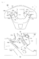
FIGS. 2A and 2B are diagrams showing independently an example of thelower cover 108 illustrated inFIG. 1 .FIG. 2A is a bottom view illustrating an overall structure of thelower cover 108. Abottom member 110 is a member facing thesteering column 102 illustrated inFIG. 1 . Formed at a center of thebottom member 110 is anopen portion 112 through which the steering shaft 104 (refer toFIG. 1 ) passes. In addition, formed on both sides of a vehicle's width direction (that nearly matches the X axis direction) are paddleswitch enclosure holes FIG. 4C ) as examples of other open portions that enclose any units. In addition, formed below the paddleswitch enclosure holes open portion 112 are slitportions buffer portions steering wheel device 100. - In the following description, the
slit portion 114a and thebuffer portion 116a as representatives of the twoslit portions buffer portions FIG. 2B is an enlarged perspective view illustrating structures of theslit portion 114a and thebuffer portion 116a illustrated inFIG. 2A . Theslit portion 114a and thebuffer portion 116a are structured to absorb a shock occurring on thelower cover 108 in case of emergency. Theslit portion 114a is a slit that forms a buffer portion on thebottom member 110 that is bent and curved in an M-shape. Thebuffer portion 116a is fringed by theslit portion 114a and formed on thebottom member 110. In addition, thebuffer portion 116a has afree end 118 on the vehicle's front side (on an upper left side of the figure) and astationary end 120 on the vehicle's rear side (on a lower right side of the figure). - According to the present embodiment, the
free end 118 of thebuffer portion 116a is formed in the M-shape having two tip portions on both width sides of thefree end 118.Bridge members slit portion 114a at the two tip portions of the M-shapedfree end 118. Thebridge members slit portion 114a between thefree end 118 of thebuffer portion 116a and an opposite region to thefree end 118 across theslit portion 114a. In a normal operation of the vehicle, thebridge members lower cover 108 and prevent thelower cover 108 from vibrating and generating a noise. -
FIGS. 3A and 3B are enlarged views illustrating a structure of thebridge member 122a illustrated inFIG. 2B . In case of emergency, when a shock is applied to the steering wheel 101 (refer toFIG. 1 ), thebridge member 122a inFIG. 3A is broken in accordance with bending in thesteering wheel 101. According to the present embodiment, anarrow width portion 124 is formed at a center of a longitudinal direction of thebridge member 122a so that thebridge member 122a is effectively broken. Thenarrow width portion 124 is narrower than neighboring portions of thebridge member 122a so that thenarrow width portion 124 is easily broken. -
FIG. 3B is a sectional view taken along line A - A ofFIG. 3A . As exemplified inFIG. 3B , according to the present embodiment, thebridge member 122a is thinner than the neighboringbottom member 110 and the neighboringbuffer portion 116a. Thus, thebridge member 122a is effectively broken compared with the neighboringbottom member 110 and the neighboringbuffer portion 116a. -
FIGS. 4A to 4D are schematic diagrams exemplifying deformation of thesteering wheel 101 illustrated inFIG. 1 when a load is applied thereto.FIG. 4A exemplifies thesteering wheel 101 mounted on a vehicle. As exemplified inFIG. 4A , thelower cover 108 is disposed between a main body (including members such as arim 103 and the air bag module 106) of thesteering wheel 101 and thesteering column 102.FIG. 4B is a partial perspective sectional view illustrating a neighboring portion of thebuffer portion 116a in thelower cover 108 illustrated inFIG. 4A. FIG. 4B exemplifies a state where a shock is not yet applied to thesteering wheel 101, hence no change has not yet occurred in thebuffer portion 116a. -
FIG. 4C exemplifies a state where a load is applied to a lower part of thesteering wheel 101 illustrated inFIG. 4A . In other words, the state illustrated inFIG. 4C denotes that how a load is applied to thesteering wheel 101 in case of emergency. When a deceleration or an acceleration occurs in a vehicle in case of emergency, an occupant inertially and almost downwardly touches any part (for example, a lower part 105) of therim 103 from an occupant's front side, namely on the vehicle's rear side (on the right side of the figure) of thesteering wheel 101. InFIG. 4C , a shock applied to thesteering wheel 101 by touching of the occupant is represented by an arrow S1. - In
FIG. 4C , apaddle shift 132 is disposed as an example of a member that passes through the paddleswitch enclosure hole 130b explained with reference toFIG. 2A . When there is a unit such as thepaddle shift 132 that passes through thelower cover 108, in a case where a load such as the shock S1 is applied, thelower cover 108 may be caused to deform and move, following therim 103. As a result, thelower cover 108 may interfere with thepaddle shift 132. Thus, thepaddle shift 132 and thelower cover 108 may malfunction. However, when thesteering wheel device 100 is used, thebuffer portion 116a illustrated inFIG. 4B functions as a means to effectively solve such a problem. -
FIG. 4D exemplifies thebuffer portion 116a in a state established when thesteering column 102 is in a state as illustrated inFIG. 4C . As exemplified inFIG. 4D , when thelower part 105 of the rim 103 (refer toFIG. 4C ) is pressed downwardly, a load is applied to thebuffer portion 116a based on the principle of leverage so that thefree end 118 is raised. As a result, thebridge members bridge members free end 118, a load can be effectively applied to thebridge members bridge members rim 103 causes a region below an extension line L1 that connects the ends of theslit portion 114a (refer toFIG. 2A ) as a bending line to be bent and deformed. This series of developments allows thelower cover 108 to absorb a shock (arrow S1 illustrated inFIG. 4C ). On the other hand, therim 103 does not remarkably cause the region above the extension line L1 of thelower cover 108 to be largely deformed and moved. As a result, thelower cover 108 can be prevented from interfering with thepaddle shift 132 exemplified inFIG. 4C . - If an occupant touches the
steering wheel 101 according to the present embodiment, a reaction exerted on the occupant from thesteering wheel 101. In addition, only thebridge members bridge members lower cover 108 can be regularly deformed as designed. Thus, when thelower cover 108 is deformed, it can be prevented from interfering with thepaddle shift 132 and other inner structures of thesteering wheel 101. In addition, since only thebridge members lower cover 108 are prevented, scattering of broken pieces is inhibited. Thus, thesteering wheel 101 is advantageous from a safety point of view. -
FIGS. 5A to 5C illustrate bridge members according to modifications of thebridge member 122a illustrated inFIGS. 3A and 3B . As exemplified inFIG. 5A , agroove portion 202 is formed at a center in a longitudinal direction of abridge member 200 so that thegroove portion 202 extends for a width of thebridge member 200.FIG. 5B is a sectional view taken along line B - B ofFIG. 5A . As shown inFIG. 5B , the proveportion 202 may be provided in the form of a cut. Since thegroove portion 202 allows a load to be concentrated thereto, thebridge member 200 can be effectively broken along thegroove portion 202. -
FIG. 5C is a schematic diagram exemplifying abridge member 300 according to another modification of the present invention. Unlike thebridge member 122a illustrated inFIG. 3A and FIG. 3B , thebridge member 300 is linearly formed. Since anarrow width portion 302 is formed at a center in a longitudinal direction of thebridge member 300, thebridge member 300 can be easily broken. -
FIGS. 6A and 6B are diagrams illustrating modifications of theslit portion 114a and thebuffer portion 116a illustrated inFIGS. 2A and 2B . As exemplified inFIG. 6A , slitportions buffer portions buffer portions FIG. 6B , slitportions buffer portions slit portion 500a are formed in U-shapes. When shocks are applied to these structures, since thebridge members lower cover 108 is bent, the shocks can be absorbed. - With reference to the accompanying drawings, preferred embodiments of the present invention have been described. The foregoing embodiments are preferred embodiments of the present invention. Thus, other embodiments can be implemented or accomplished based on various methods. The present invention is not limited by shapes, dimensions, structures, arrangements, and so forth of members and portions illustrated in the accompanying drawings unless otherwise described in the specification of the present application. Expression and terms used in the specification of the present application intend to describe the present invention, but not limited thereto unless otherwise described therein.
- Thus, it is clear that those skilled in the art can contemplate various modifications or corrections of the present invention without departing from the scope of claims. Those skilled in the art know that these modifications or corrections of the present invention belong to the technical scope of the present invention.
- The present invention can be applied to a steering wheel device including a steering wheel connected with a steering column of a vehicle and a lower cover that covers a steering column side of the steering wheel.
Claims (7)
- A steering wheel device comprising:a steering wheel that is connected with a steering column of a vehicle; anda lower cover that covers a steering column side of the steering wheel, whereinthe lower cover includes:a bottom member facing the steering column;an open portion which is formed at a center of the bottom member and through which a steering shaft extending from the steering column to the steering wheel passes;slit portions formed on both sides, in a vehicle width direction, of the open portion of the bottom member, with the slit portions being bent and curved in predetermined shapes;buffer portions formed in the bottom member and fringed by the slit portions, with these buffer portions each having a free end formed on a vehicle front side and a stationary end formed on a vehicle rear side; andbridge members that can be broken and bridge respective slit portions on the free end side of each of the buffer portions.
- The steering wheel device according to claim 1,
wherein the bridge members are thinner than the bottom member. - The steering wheel device according to claim 1 or 2,
wherein the bridge members each have a narrow width portion formed at a center thereof in a longitudinal direction, the narrow width portion being narrower than a neighboring portion of each of the bridge members. - The steering wheel device according to any one of claims 1 to 3,
wherein the bridge members each have a slit portion formed at the center thereof in the longitudinal direction, with the groove portion being formed to extend over a width of each of the bridge members. - The steering wheel device according to any one of claims 1 to 4, wherein
the free end of each of the buffer portions is formed in an M shape, and
the bridge members bridge two tip portions of the M-shape of the free end. - The steering wheel device according to any one of claims 1 to 4,
wherein the free end of each of the buffer portions is formed in an arc shape. - The steering wheel device according to any one of claim 1 to 4,
wherein the free end of each of the buffer portions is formed in a U-shape.
Applications Claiming Priority (2)
| Application Number | Priority Date | Filing Date | Title |
|---|---|---|---|
| JP2012287553 | 2012-12-28 | ||
| PCT/JP2013/083472 WO2014103752A1 (en) | 2012-12-28 | 2013-12-13 | Steering wheel device |
Publications (3)
| Publication Number | Publication Date |
|---|---|
| EP2939905A1 true EP2939905A1 (en) | 2015-11-04 |
| EP2939905A4 EP2939905A4 (en) | 2016-08-17 |
| EP2939905B1 EP2939905B1 (en) | 2017-10-11 |
Family
ID=51020840
Family Applications (1)
| Application Number | Title | Priority Date | Filing Date |
|---|---|---|---|
| EP13867354.6A Active EP2939905B1 (en) | 2012-12-28 | 2013-12-13 | Steering wheel device |
Country Status (5)
| Country | Link |
|---|---|
| US (1) | US10239551B2 (en) |
| EP (1) | EP2939905B1 (en) |
| JP (1) | JP5933036B2 (en) |
| CN (1) | CN104884332B (en) |
| WO (1) | WO2014103752A1 (en) |
Family Cites Families (21)
| Publication number | Priority date | Publication date | Assignee | Title |
|---|---|---|---|---|
| DE2530594C3 (en) * | 1975-07-09 | 1979-02-08 | Volkswagenwerk Ag, 3180 Wolfsburg | steering wheel |
| US4116087A (en) * | 1975-08-08 | 1978-09-26 | Firma Petri Ag | Energy absorbing structure for the steering column of a motor vehicle |
| DE2614041A1 (en) * | 1976-04-01 | 1977-10-06 | Petri Ag | ENERGY ABSORPTION ELEMENT |
| FR2463708A1 (en) * | 1979-08-20 | 1981-02-27 | Brun Jean | Shock absorber assembly for car steering wheel - has deformable barrel with slits placed between wheel and column |
| JPH0326052Y2 (en) * | 1985-12-13 | 1991-06-05 | ||
| JPH04224463A (en) * | 1990-12-25 | 1992-08-13 | Tokyo Seat Kk | Steering wheel for vehicle |
| US5356178A (en) * | 1992-04-20 | 1994-10-18 | Ryusaku Numata | Energy absorbing steering wheel |
| JP3313951B2 (en) * | 1995-09-11 | 2002-08-12 | 株式会社東海理化電機製作所 | Steering device |
| JPH107002A (en) * | 1996-06-18 | 1998-01-13 | Toyoda Gosei Co Ltd | Steering wheel |
| DE10144143C1 (en) * | 2001-09-10 | 2002-08-14 | Kostal Leopold Gmbh & Co Kg | Torsion module for a torque detection device |
| DE202004006494U1 (en) * | 2004-04-21 | 2004-07-22 | Takata-Petri Ag | Energy absorbing steering wheel |
| KR100634604B1 (en) * | 2004-08-11 | 2006-10-13 | 현대자동차주식회사 | Engine output torque measuring device for automatic transmission vehicle |
| CN2892617Y (en) * | 2006-03-03 | 2007-04-25 | 上海通用汽车有限公司 | Automobile steering wheel with protection device |
| US8505410B2 (en) * | 2006-08-31 | 2013-08-13 | Autoliv Asp, Inc. | Two-piece steering wheel back-cover for improved safety performance |
| JP5230867B2 (en) * | 2008-08-29 | 2013-07-10 | 日本プラスト株式会社 | Vehicle steering wheel |
| JP2010125990A (en) * | 2008-11-27 | 2010-06-10 | Nippon Plast Co Ltd | Steering wheel |
| JP2010152664A (en) | 2008-12-25 | 2010-07-08 | Nissei Corp | Sensorless motor-driven robot using image |
| DE102009057809A1 (en) * | 2009-12-10 | 2011-06-16 | Leopold Kostal Gmbh & Co. Kg | torsion |
| DE102010017851B4 (en) * | 2010-04-22 | 2023-12-07 | Kostal Automobil Elektrik Gmbh & Co. Kg | Torsion module |
| JP5327164B2 (en) * | 2010-08-24 | 2013-10-30 | 日本精工株式会社 | Shock absorbing steering device with electric power steering device |
| JP5327165B2 (en) * | 2010-08-26 | 2013-10-30 | 日本精工株式会社 | Shock absorbing steering device with electric power steering device |
-
2013
- 2013-12-13 WO PCT/JP2013/083472 patent/WO2014103752A1/en not_active Ceased
- 2013-12-13 JP JP2014554317A patent/JP5933036B2/en active Active
- 2013-12-13 CN CN201380068160.3A patent/CN104884332B/en active Active
- 2013-12-13 US US14/758,355 patent/US10239551B2/en active Active
- 2013-12-13 EP EP13867354.6A patent/EP2939905B1/en active Active
Also Published As
| Publication number | Publication date |
|---|---|
| EP2939905A4 (en) | 2016-08-17 |
| US10239551B2 (en) | 2019-03-26 |
| CN104884332B (en) | 2017-09-29 |
| JP5933036B2 (en) | 2016-06-08 |
| JPWO2014103752A1 (en) | 2017-01-12 |
| WO2014103752A1 (en) | 2014-07-03 |
| CN104884332A (en) | 2015-09-02 |
| US20150353120A1 (en) | 2015-12-10 |
| EP2939905B1 (en) | 2017-10-11 |
Similar Documents
| Publication | Publication Date | Title |
|---|---|---|
| JP5318720B2 (en) | Electronic control unit | |
| JP4645247B2 (en) | Fuel tank structure | |
| WO2014007403A1 (en) | Vehicle body front portion structure | |
| JP2007137336A (en) | Collision detection device and protection device | |
| KR102523182B1 (en) | steering wheel | |
| JP4798459B2 (en) | Vehicle collision detection device | |
| JP2010132202A (en) | Sensor device and vehicle with the same | |
| JP5170140B2 (en) | Vehicle collision detection device | |
| JP2005138819A (en) | Mounting structure of steering column for automobile | |
| WO2013080753A1 (en) | Steering wheel | |
| EP2939905B1 (en) | Steering wheel device | |
| JP7698974B2 (en) | Control device | |
| JP2010047110A (en) | Collision detection device for vehicle | |
| KR101405848B1 (en) | Knee-bolster for vehicle | |
| JP2018144611A (en) | Vehicle front part structure | |
| JP5230867B2 (en) | Vehicle steering wheel | |
| JP2019059424A (en) | Vehicle body front part structure | |
| JP2009248737A (en) | Glove box | |
| JP2014101025A (en) | Steering wheel | |
| CN224090159U (en) | Airbag securing structure and airbag securing system for vehicles | |
| KR100309032B1 (en) | Nibolster device of automobile | |
| US20100154737A1 (en) | Vehicle air cleaner mounting structure | |
| JP5111768B2 (en) | Steering wheel core metal structure | |
| JPH06234343A (en) | Occupant protecting device for automobile | |
| JP2010125990A (en) | Steering wheel |
Legal Events
| Date | Code | Title | Description |
|---|---|---|---|
| PUAI | Public reference made under article 153(3) epc to a published international application that has entered the european phase |
Free format text: ORIGINAL CODE: 0009012 |
|
| 17P | Request for examination filed |
Effective date: 20150629 |
|
| AK | Designated contracting states |
Kind code of ref document: A1 Designated state(s): AL AT BE BG CH CY CZ DE DK EE ES FI FR GB GR HR HU IE IS IT LI LT LU LV MC MK MT NL NO PL PT RO RS SE SI SK SM TR |
|
| AX | Request for extension of the european patent |
Extension state: BA ME |
|
| DAX | Request for extension of the european patent (deleted) | ||
| A4 | Supplementary search report drawn up and despatched |
Effective date: 20160715 |
|
| RIC1 | Information provided on ipc code assigned before grant |
Ipc: B62D 1/11 20060101AFI20160712BHEP Ipc: F16F 7/12 20060101ALI20160712BHEP Ipc: F16F 7/00 20060101ALI20160712BHEP |
|
| GRAP | Despatch of communication of intention to grant a patent |
Free format text: ORIGINAL CODE: EPIDOSNIGR1 |
|
| INTG | Intention to grant announced |
Effective date: 20170511 |
|
| GRAS | Grant fee paid |
Free format text: ORIGINAL CODE: EPIDOSNIGR3 |
|
| GRAA | (expected) grant |
Free format text: ORIGINAL CODE: 0009210 |
|
| AK | Designated contracting states |
Kind code of ref document: B1 Designated state(s): AL AT BE BG CH CY CZ DE DK EE ES FI FR GB GR HR HU IE IS IT LI LT LU LV MC MK MT NL NO PL PT RO RS SE SI SK SM TR |
|
| REG | Reference to a national code |
Ref country code: GB Ref legal event code: FG4D |
|
| REG | Reference to a national code |
Ref country code: CH Ref legal event code: EP |
|
| REG | Reference to a national code |
Ref country code: IE Ref legal event code: FG4D |
|
| REG | Reference to a national code |
Ref country code: AT Ref legal event code: REF Ref document number: 935744 Country of ref document: AT Kind code of ref document: T Effective date: 20171115 |
|
| REG | Reference to a national code |
Ref country code: DE Ref legal event code: R096 Ref document number: 602013027964 Country of ref document: DE |
|
| REG | Reference to a national code |
Ref country code: FR Ref legal event code: PLFP Year of fee payment: 5 |
|
| REG | Reference to a national code |
Ref country code: NL Ref legal event code: MP Effective date: 20171011 |
|
| REG | Reference to a national code |
Ref country code: LT Ref legal event code: MG4D |
|
| REG | Reference to a national code |
Ref country code: AT Ref legal event code: MK05 Ref document number: 935744 Country of ref document: AT Kind code of ref document: T Effective date: 20171011 |
|
| PG25 | Lapsed in a contracting state [announced via postgrant information from national office to epo] |
Ref country code: NL Free format text: LAPSE BECAUSE OF FAILURE TO SUBMIT A TRANSLATION OF THE DESCRIPTION OR TO PAY THE FEE WITHIN THE PRESCRIBED TIME-LIMIT Effective date: 20171011 |
|
| PG25 | Lapsed in a contracting state [announced via postgrant information from national office to epo] |
Ref country code: FI Free format text: LAPSE BECAUSE OF FAILURE TO SUBMIT A TRANSLATION OF THE DESCRIPTION OR TO PAY THE FEE WITHIN THE PRESCRIBED TIME-LIMIT Effective date: 20171011 Ref country code: LT Free format text: LAPSE BECAUSE OF FAILURE TO SUBMIT A TRANSLATION OF THE DESCRIPTION OR TO PAY THE FEE WITHIN THE PRESCRIBED TIME-LIMIT Effective date: 20171011 Ref country code: SE Free format text: LAPSE BECAUSE OF FAILURE TO SUBMIT A TRANSLATION OF THE DESCRIPTION OR TO PAY THE FEE WITHIN THE PRESCRIBED TIME-LIMIT Effective date: 20171011 Ref country code: ES Free format text: LAPSE BECAUSE OF FAILURE TO SUBMIT A TRANSLATION OF THE DESCRIPTION OR TO PAY THE FEE WITHIN THE PRESCRIBED TIME-LIMIT Effective date: 20171011 Ref country code: NO Free format text: LAPSE BECAUSE OF FAILURE TO SUBMIT A TRANSLATION OF THE DESCRIPTION OR TO PAY THE FEE WITHIN THE PRESCRIBED TIME-LIMIT Effective date: 20180111 |
|
| PG25 | Lapsed in a contracting state [announced via postgrant information from national office to epo] |
Ref country code: BG Free format text: LAPSE BECAUSE OF FAILURE TO SUBMIT A TRANSLATION OF THE DESCRIPTION OR TO PAY THE FEE WITHIN THE PRESCRIBED TIME-LIMIT Effective date: 20180111 Ref country code: LV Free format text: LAPSE BECAUSE OF FAILURE TO SUBMIT A TRANSLATION OF THE DESCRIPTION OR TO PAY THE FEE WITHIN THE PRESCRIBED TIME-LIMIT Effective date: 20171011 Ref country code: IS Free format text: LAPSE BECAUSE OF FAILURE TO SUBMIT A TRANSLATION OF THE DESCRIPTION OR TO PAY THE FEE WITHIN THE PRESCRIBED TIME-LIMIT Effective date: 20180211 Ref country code: HR Free format text: LAPSE BECAUSE OF FAILURE TO SUBMIT A TRANSLATION OF THE DESCRIPTION OR TO PAY THE FEE WITHIN THE PRESCRIBED TIME-LIMIT Effective date: 20171011 Ref country code: GR Free format text: LAPSE BECAUSE OF FAILURE TO SUBMIT A TRANSLATION OF THE DESCRIPTION OR TO PAY THE FEE WITHIN THE PRESCRIBED TIME-LIMIT Effective date: 20180112 Ref country code: RS Free format text: LAPSE BECAUSE OF FAILURE TO SUBMIT A TRANSLATION OF THE DESCRIPTION OR TO PAY THE FEE WITHIN THE PRESCRIBED TIME-LIMIT Effective date: 20171011 Ref country code: AT Free format text: LAPSE BECAUSE OF FAILURE TO SUBMIT A TRANSLATION OF THE DESCRIPTION OR TO PAY THE FEE WITHIN THE PRESCRIBED TIME-LIMIT Effective date: 20171011 |
|
| REG | Reference to a national code |
Ref country code: DE Ref legal event code: R097 Ref document number: 602013027964 Country of ref document: DE |
|
| PG25 | Lapsed in a contracting state [announced via postgrant information from national office to epo] |
Ref country code: CZ Free format text: LAPSE BECAUSE OF FAILURE TO SUBMIT A TRANSLATION OF THE DESCRIPTION OR TO PAY THE FEE WITHIN THE PRESCRIBED TIME-LIMIT Effective date: 20171011 Ref country code: EE Free format text: LAPSE BECAUSE OF FAILURE TO SUBMIT A TRANSLATION OF THE DESCRIPTION OR TO PAY THE FEE WITHIN THE PRESCRIBED TIME-LIMIT Effective date: 20171011 Ref country code: DK Free format text: LAPSE BECAUSE OF FAILURE TO SUBMIT A TRANSLATION OF THE DESCRIPTION OR TO PAY THE FEE WITHIN THE PRESCRIBED TIME-LIMIT Effective date: 20171011 Ref country code: SK Free format text: LAPSE BECAUSE OF FAILURE TO SUBMIT A TRANSLATION OF THE DESCRIPTION OR TO PAY THE FEE WITHIN THE PRESCRIBED TIME-LIMIT Effective date: 20171011 |
|
| REG | Reference to a national code |
Ref country code: CH Ref legal event code: PL |
|
| PLBE | No opposition filed within time limit |
Free format text: ORIGINAL CODE: 0009261 |
|
| STAA | Information on the status of an ep patent application or granted ep patent |
Free format text: STATUS: NO OPPOSITION FILED WITHIN TIME LIMIT |
|
| PG25 | Lapsed in a contracting state [announced via postgrant information from national office to epo] |
Ref country code: IT Free format text: LAPSE BECAUSE OF FAILURE TO SUBMIT A TRANSLATION OF THE DESCRIPTION OR TO PAY THE FEE WITHIN THE PRESCRIBED TIME-LIMIT Effective date: 20171011 Ref country code: RO Free format text: LAPSE BECAUSE OF FAILURE TO SUBMIT A TRANSLATION OF THE DESCRIPTION OR TO PAY THE FEE WITHIN THE PRESCRIBED TIME-LIMIT Effective date: 20171011 Ref country code: SM Free format text: LAPSE BECAUSE OF FAILURE TO SUBMIT A TRANSLATION OF THE DESCRIPTION OR TO PAY THE FEE WITHIN THE PRESCRIBED TIME-LIMIT Effective date: 20171011 Ref country code: PL Free format text: LAPSE BECAUSE OF FAILURE TO SUBMIT A TRANSLATION OF THE DESCRIPTION OR TO PAY THE FEE WITHIN THE PRESCRIBED TIME-LIMIT Effective date: 20171011 |
|
| 26N | No opposition filed |
Effective date: 20180712 |
|
| REG | Reference to a national code |
Ref country code: IE Ref legal event code: MM4A |
|
| PG25 | Lapsed in a contracting state [announced via postgrant information from national office to epo] |
Ref country code: LU Free format text: LAPSE BECAUSE OF NON-PAYMENT OF DUE FEES Effective date: 20171213 Ref country code: MT Free format text: LAPSE BECAUSE OF NON-PAYMENT OF DUE FEES Effective date: 20171213 |
|
| REG | Reference to a national code |
Ref country code: BE Ref legal event code: MM Effective date: 20171231 |
|
| PG25 | Lapsed in a contracting state [announced via postgrant information from national office to epo] |
Ref country code: IE Free format text: LAPSE BECAUSE OF NON-PAYMENT OF DUE FEES Effective date: 20171213 |
|
| PG25 | Lapsed in a contracting state [announced via postgrant information from national office to epo] |
Ref country code: CH Free format text: LAPSE BECAUSE OF NON-PAYMENT OF DUE FEES Effective date: 20171231 Ref country code: BE Free format text: LAPSE BECAUSE OF NON-PAYMENT OF DUE FEES Effective date: 20171231 Ref country code: SI Free format text: LAPSE BECAUSE OF FAILURE TO SUBMIT A TRANSLATION OF THE DESCRIPTION OR TO PAY THE FEE WITHIN THE PRESCRIBED TIME-LIMIT Effective date: 20171011 Ref country code: LI Free format text: LAPSE BECAUSE OF NON-PAYMENT OF DUE FEES Effective date: 20171231 |
|
| PGFP | Annual fee paid to national office [announced via postgrant information from national office to epo] |
Ref country code: TR Payment date: 20181106 Year of fee payment: 9 |
|
| PG25 | Lapsed in a contracting state [announced via postgrant information from national office to epo] |
Ref country code: HU Free format text: LAPSE BECAUSE OF FAILURE TO SUBMIT A TRANSLATION OF THE DESCRIPTION OR TO PAY THE FEE WITHIN THE PRESCRIBED TIME-LIMIT; INVALID AB INITIO Effective date: 20131213 Ref country code: MC Free format text: LAPSE BECAUSE OF FAILURE TO SUBMIT A TRANSLATION OF THE DESCRIPTION OR TO PAY THE FEE WITHIN THE PRESCRIBED TIME-LIMIT Effective date: 20171011 |
|
| PG25 | Lapsed in a contracting state [announced via postgrant information from national office to epo] |
Ref country code: CY Free format text: LAPSE BECAUSE OF FAILURE TO SUBMIT A TRANSLATION OF THE DESCRIPTION OR TO PAY THE FEE WITHIN THE PRESCRIBED TIME-LIMIT Effective date: 20171011 |
|
| PG25 | Lapsed in a contracting state [announced via postgrant information from national office to epo] |
Ref country code: MK Free format text: LAPSE BECAUSE OF FAILURE TO SUBMIT A TRANSLATION OF THE DESCRIPTION OR TO PAY THE FEE WITHIN THE PRESCRIBED TIME-LIMIT Effective date: 20171011 |
|
| PG25 | Lapsed in a contracting state [announced via postgrant information from national office to epo] |
Ref country code: TR Free format text: LAPSE BECAUSE OF FAILURE TO SUBMIT A TRANSLATION OF THE DESCRIPTION OR TO PAY THE FEE WITHIN THE PRESCRIBED TIME-LIMIT Effective date: 20171011 |
|
| PG25 | Lapsed in a contracting state [announced via postgrant information from national office to epo] |
Ref country code: PT Free format text: LAPSE BECAUSE OF FAILURE TO SUBMIT A TRANSLATION OF THE DESCRIPTION OR TO PAY THE FEE WITHIN THE PRESCRIBED TIME-LIMIT Effective date: 20171011 |
|
| PG25 | Lapsed in a contracting state [announced via postgrant information from national office to epo] |
Ref country code: AL Free format text: LAPSE BECAUSE OF FAILURE TO SUBMIT A TRANSLATION OF THE DESCRIPTION OR TO PAY THE FEE WITHIN THE PRESCRIBED TIME-LIMIT Effective date: 20171011 |
|
| GBPC | Gb: european patent ceased through non-payment of renewal fee |
Effective date: 20191213 |
|
| PG25 | Lapsed in a contracting state [announced via postgrant information from national office to epo] |
Ref country code: GB Free format text: LAPSE BECAUSE OF NON-PAYMENT OF DUE FEES Effective date: 20191213 |
|
| P01 | Opt-out of the competence of the unified patent court (upc) registered |
Effective date: 20230507 |
|
| PGFP | Annual fee paid to national office [announced via postgrant information from national office to epo] |
Ref country code: FR Payment date: 20251223 Year of fee payment: 13 |
|
| PGFP | Annual fee paid to national office [announced via postgrant information from national office to epo] |
Ref country code: DE Payment date: 20251229 Year of fee payment: 13 |