EP2939872A1 - Power seat with complete manual walk-in system - Google Patents
Power seat with complete manual walk-in system Download PDFInfo
- Publication number
- EP2939872A1 EP2939872A1 EP14199243.8A EP14199243A EP2939872A1 EP 2939872 A1 EP2939872 A1 EP 2939872A1 EP 14199243 A EP14199243 A EP 14199243A EP 2939872 A1 EP2939872 A1 EP 2939872A1
- Authority
- EP
- European Patent Office
- Prior art keywords
- seat
- lock lever
- seat back
- walk
- lead screw
- Prior art date
- Legal status (The legal status is an assumption and is not a legal conclusion. Google has not performed a legal analysis and makes no representation as to the accuracy of the status listed.)
- Granted
Links
- 230000007246 mechanism Effects 0.000 claims abstract description 25
- 230000004044 response Effects 0.000 claims description 4
- 238000013461 design Methods 0.000 description 10
- 238000000034 method Methods 0.000 description 3
- 230000007935 neutral effect Effects 0.000 description 3
- 238000013459 approach Methods 0.000 description 1
- 230000000712 assembly Effects 0.000 description 1
- 238000000429 assembly Methods 0.000 description 1
- 230000000694 effects Effects 0.000 description 1
- 238000012986 modification Methods 0.000 description 1
- 230000004048 modification Effects 0.000 description 1
- 238000004806 packaging method and process Methods 0.000 description 1
Images


Classifications
-
- B—PERFORMING OPERATIONS; TRANSPORTING
- B60—VEHICLES IN GENERAL
- B60N—SEATS SPECIALLY ADAPTED FOR VEHICLES; VEHICLE PASSENGER ACCOMMODATION NOT OTHERWISE PROVIDED FOR
- B60N2/00—Seats specially adapted for vehicles; Arrangement or mounting of seats in vehicles
- B60N2/02—Seats specially adapted for vehicles; Arrangement or mounting of seats in vehicles the seat or part thereof being movable, e.g. adjustable
- B60N2/22—Seats specially adapted for vehicles; Arrangement or mounting of seats in vehicles the seat or part thereof being movable, e.g. adjustable the back-rest being adjustable
- B60N2/2227—Seats specially adapted for vehicles; Arrangement or mounting of seats in vehicles the seat or part thereof being movable, e.g. adjustable the back-rest being adjustable and provided with braking systems
-
- B—PERFORMING OPERATIONS; TRANSPORTING
- B60—VEHICLES IN GENERAL
- B60N—SEATS SPECIALLY ADAPTED FOR VEHICLES; VEHICLE PASSENGER ACCOMMODATION NOT OTHERWISE PROVIDED FOR
- B60N2/00—Seats specially adapted for vehicles; Arrangement or mounting of seats in vehicles
- B60N2/02—Seats specially adapted for vehicles; Arrangement or mounting of seats in vehicles the seat or part thereof being movable, e.g. adjustable
- B60N2/04—Seats specially adapted for vehicles; Arrangement or mounting of seats in vehicles the seat or part thereof being movable, e.g. adjustable the whole seat being movable
- B60N2/06—Seats specially adapted for vehicles; Arrangement or mounting of seats in vehicles the seat or part thereof being movable, e.g. adjustable the whole seat being movable slidable
- B60N2/067—Seats specially adapted for vehicles; Arrangement or mounting of seats in vehicles the seat or part thereof being movable, e.g. adjustable the whole seat being movable slidable by linear actuators, e.g. linear screw mechanisms
-
- B—PERFORMING OPERATIONS; TRANSPORTING
- B60—VEHICLES IN GENERAL
- B60N—SEATS SPECIALLY ADAPTED FOR VEHICLES; VEHICLE PASSENGER ACCOMMODATION NOT OTHERWISE PROVIDED FOR
- B60N2/00—Seats specially adapted for vehicles; Arrangement or mounting of seats in vehicles
- B60N2/02—Seats specially adapted for vehicles; Arrangement or mounting of seats in vehicles the seat or part thereof being movable, e.g. adjustable
- B60N2/04—Seats specially adapted for vehicles; Arrangement or mounting of seats in vehicles the seat or part thereof being movable, e.g. adjustable the whole seat being movable
- B60N2/06—Seats specially adapted for vehicles; Arrangement or mounting of seats in vehicles the seat or part thereof being movable, e.g. adjustable the whole seat being movable slidable
- B60N2/07—Slide construction
- B60N2/0722—Constructive details
-
- B—PERFORMING OPERATIONS; TRANSPORTING
- B60—VEHICLES IN GENERAL
- B60N—SEATS SPECIALLY ADAPTED FOR VEHICLES; VEHICLE PASSENGER ACCOMMODATION NOT OTHERWISE PROVIDED FOR
- B60N2/00—Seats specially adapted for vehicles; Arrangement or mounting of seats in vehicles
- B60N2/02—Seats specially adapted for vehicles; Arrangement or mounting of seats in vehicles the seat or part thereof being movable, e.g. adjustable
- B60N2/04—Seats specially adapted for vehicles; Arrangement or mounting of seats in vehicles the seat or part thereof being movable, e.g. adjustable the whole seat being movable
- B60N2/12—Seats specially adapted for vehicles; Arrangement or mounting of seats in vehicles the seat or part thereof being movable, e.g. adjustable the whole seat being movable slidable and tiltable
- B60N2/123—Seats specially adapted for vehicles; Arrangement or mounting of seats in vehicles the seat or part thereof being movable, e.g. adjustable the whole seat being movable slidable and tiltable and provided with memory locks
Definitions
- Exemplary aspects of the present invention relate to a manually operated walk-in system of a powered vehicle seat.
- Seats of a vehicle such as an automobile may be provided with a reclining mechanism that allows the seat back to pivot at a base portion thereof. These seats may also be provided with a sliding mechanism that allows the seat to travel in the fore-aft direction of the vehicle. Both the reclining mechanism and the sliding mechanism may be operated using individual manual levers, typically located on the vehicle seat. Also the reclining mechanism and the sliding mechanism may be replaced by a powered actuator that performs the sliding and reclining functions without additional effort from the user. Seats equipped with these features are typically called power seats or power assisted seats.
- Seats may also include a walk-in feature that assists the egress and ingress of the vehicle.
- the walk-in feature allows one to more easily enter a space behind the seat by moving the seat forward and by rotating the seatback forward. Therefore, the walk-in feature has a recliner function and/or a slide function. These walk-in functions can be powered or manually actuated.
- the sliding mechanism is locked in order to prevent the seat from traveling in the fore-aft direction of the vehicle.
- the sliding mechanism is locked by the connection between a lock lever fixed to the vehicle and a lead screw nut fixed to the seat.
- interdigitated teeth are used to connect the lock lever to the lead screw.
- recesses in the lead screw nut correspond to raised teeth from the lock lever, whereby the teeth of the lock lever occupy the recesses in the lead screw nut and prevent motion in the fore-aft direction. If the teeth are retracted from the recesses in the lead screw nut, then motion in the fore-aft direction is allowed.
- U.S. patent No. 5,516,071 illustrates a conventional walk-in mechanism.
- interdigitated teeth design One challenge with the interdigitated teeth design is that during a crash, extreme force on the teeth may cause the teeth bend resulting in the failure of the lock and the seat sliding the fore-aft direction.
- a second challenge is that the interdigitated teeth design occupies significant space due to the way in which the lock lever teeth are retracted from the recesses in the lead screw nut.
- the invention aims at solving at least partly one or more of the problems referenced above.
- the invention concerns a seat including a seat back, a walk-in lever that releases the seat back so that the seat back may rotate, a slide mechanism having an upper rail and lower rail, whereby the seat moves in the fore-aft direction due to motion of the upper rail relative to the lower rail, a connection device between the seat back and a slide mechanism that releases the slide mechanism, wherein rotation of the seat back by a predetermined amount releases the slide mechanism so that the seat may slide in a fore-aft direction.
- the seat preferably includes a lock lever that rotates in response to rotation of the seat back, and a lead screw nut provided that is locked in place by the lock lever.
- the lock lever In a locked position, the lock lever is preferably configured to be in direct contact with the lower rail such that forward force on the seat is transferred directly from the lock lever to the lower rail at the point of contact between the lock lever and the lower rail.
- a vehicle refers to a land vehicle exemplified by an automobile.
- the present disclosure is also applicable to any similar type vehicle, such as but not limited to, a sport utility vehicle, a pickup truck, a commercial vehicle, a boat an airplane or the like.
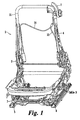
- Figure 1 illustrates a seat 1 including a frame 11 provided with power recliners 2 on each side of the seat 1 and a power seat slide 3 located at the bottom of the frame 11.
- the power recliners 2 rotate the seat back in around an axis in a generally fore-aft direction.
- the power seat slide 3 moves the seat in the fore-aft direction by sliding the seat 1 on the respective inner rail 5 and outer rail 6. Both the inner rail 5 and the outer rail 6 are lower rails.
- Figure 1 also illustrates a walk-in lever 7 found at a top portion of the seat frame 11.
- the walk-in lever 7 here is illustrated in a shoulder area of the seat 1.
- Cable A which has a first leg 14 and a second leg 15, is attached to the walk-in lever 7. When the handle 8 is operated, the cable A is moved in response.
- Cable A is an example of a connection device, but other means such as a linkage, lever, chain, or the like may also be used.
- the respective legs 14 and 15 of Cable A extend to the inner and outer power recliners 2.
- the legs 14 and 15 of the cable A are arranged so that the operation of the walk-in lever 7 will effect actuation simultaneously at each of the inner and outer power recliners 2.
- the power recliner 2 releases its manual walk-in system. Thereafter, the seat back 4 is able to rotate forward to operate a walk-in procedure.
- a spring bias is provided which urges the seat back 4 forward once the manual walk-in system is released by the movement of the cable A.
- Cable B is arranged so that the forward rotation of the seat back 4 causes cable B to move in response.
- cable B is connected to a wire clamp 17 that is connected to a lock lever 18.
- Cable B is an example of a connection device, but other means such as a linkage, lever, chain, or the like may also be used.
- Figure 4 the movement of the lock lever 18 and the wire clamp 17 is shown in a dashed line.
- the lock lever 18 rotates downward. If the wire clamp 17 is moved a sufficient distance, then the lock lever 18 rotates down and out of contact with the lead screw nut 19, thereby allowing the seat track to move forward.
- the lead screw nut 19 is provided a lead screw 23, the nut including a through-hole through which the lead screw 23 penetrates.
- the lead screw nut includes a recess on a bottom portion thereof, the recess interacting with an edge of the lock lever 18. This recess can be seen for example in Figure 2 and orthogonally at Figure 6 .
- the lead screw nut also contacts a bracket 25 which is connected to outer rail 26. The bracket 25 restricts the lead screw nut from moving rearward along the lead screw 23.
- the lock lever 18 includes a cam surface at a first end, this cam surface interacting with the lead screw nut 19.
- the lock lever 18 includes a through-hole at a second end, which allows the lock lever 18 to rotate around a rail that penetrates the through-hole, the rail extending from connecting rod 21.
- the lock lever 18 is able to rotate around this rail so that the cam surface can engage and disengage with the recess of the lead screw nut 19.
- Figure 3 illustrates the movement of the seat track in the forward direction after the lock lever 18 releases the lead screw nut 19.
- the lower rail, where the lead screw nut 19 slides, is flat with no caulking pins which allows the track to slide to a forward most position.
- Movement of the seat back 4 rearward causes the reverse of the movement described above.
- the movement of the seat back 4 rearward causes the cable B wire pull lever 16 to move in the opposite direction. This causes the cable B to move leftward toward the original position shown in Figure 2 .
- the lock lever 18 returns to the locked position due to a bias force.
- Figure 4 illustrates the track sliding rearward and the lead screw nut 19 is approaching the lock lever 18.
- the lock lever 18 can pivot in the clockwise direction, but is prevented from rotating in the counterclockwise direction due to the presence of the outer rail 6.
- the lock lever 18 rotates in a counterclockwise direction allowing the lead screw nut 19 to pass over the lock lever 18, should the lock lever 18 be in the locked position due to the movement of the seat back 4.
- the lead screw nut 19 would force the lock lever 18 down and counterclockwise temporarily against a biasing force that holds the lock lever 18 up in the locked position.
- the rotating lock lever 18 has several advantages over alternative designs.
- First, the rotating lock lever design has a low profile under the rail allowing for improved packaging. That is, a distance in the vertical direction below the lower rail is reduced compared to a conventional arrangement.
- Second, the rotating lock lever design has greater strength than alternative designs because it transfers the load of a forward force directly to the lower rail, as shown in Figure 5 .
- first contact point 31 is formed by the cam surface of the lock lever 18 and the recess of the lead screw nut 19.
- the forward force will be transferred through the lead screw nut 19 to the lock lever 18 at the first contact point 31.
- the forward force will then be transferred through the lock lever 18 directly to the outer rail 6 at a second contact point 32.
- the lock lever 18 is connected by a rail to bracket 27 attached to or part of the outer rail 6. Because the forward force is transferred directly to the outer rail 6 at the second contact point 32, this lock lever is a high strength design than alternative designs with interdigitated teeth thus reducing risk of failure of the lock lever during a crash.
- Both the inner and outer seat tracks (5 and 6) may have the same components including lock levers and lead screw nuts.
- a connecting rod 21, shown in Figure 5 is provided between the respective sides so that the movement of one side also actuates the opposite side.
- Figure 5 provides a view of the one of the assemblies and the connecting rod 21.
- the mechanism described in detail above can provide a quick, manual walk-in system for a power seat with a powered slide and recliner function.
- the seat is able to slide to a forward-most position giving entry to the rear seat as large as possible.
- the mechanism uses a single manual walk-in lever to release the recliner and then both seat tracks at the same time.
Landscapes
- Engineering & Computer Science (AREA)
- Aviation & Aerospace Engineering (AREA)
- Transportation (AREA)
- Mechanical Engineering (AREA)
- Seats For Vehicles (AREA)
Abstract

Description
- Exemplary aspects of the present invention relate to a manually operated walk-in system of a powered vehicle seat.
- Seats of a vehicle such as an automobile may be provided with a reclining mechanism that allows the seat back to pivot at a base portion thereof. These seats may also be provided with a sliding mechanism that allows the seat to travel in the fore-aft direction of the vehicle. Both the reclining mechanism and the sliding mechanism may be operated using individual manual levers, typically located on the vehicle seat. Also the reclining mechanism and the sliding mechanism may be replaced by a powered actuator that performs the sliding and reclining functions without additional effort from the user. Seats equipped with these features are typically called power seats or power assisted seats.
- Seats may also include a walk-in feature that assists the egress and ingress of the vehicle. Typically, the walk-in feature allows one to more easily enter a space behind the seat by moving the seat forward and by rotating the seatback forward. Therefore, the walk-in feature has a recliner function and/or a slide function. These walk-in functions can be powered or manually actuated.
- When the walk-in function is not in use, the sliding mechanism is locked in order to prevent the seat from traveling in the fore-aft direction of the vehicle. The sliding mechanism is locked by the connection between a lock lever fixed to the vehicle and a lead screw nut fixed to the seat. In some designs, interdigitated teeth are used to connect the lock lever to the lead screw. In the interdigitated teeth designs, recesses in the lead screw nut correspond to raised teeth from the lock lever, whereby the teeth of the lock lever occupy the recesses in the lead screw nut and prevent motion in the fore-aft direction. If the teeth are retracted from the recesses in the lead screw nut, then motion in the fore-aft direction is allowed.
U.S. patent No. 5,516,071 illustrates a conventional walk-in mechanism. - One challenge with the interdigitated teeth design is that during a crash, extreme force on the teeth may cause the teeth bend resulting in the failure of the lock and the seat sliding the fore-aft direction. A second challenge is that the interdigitated teeth design occupies significant space due to the way in which the lock lever teeth are retracted from the recesses in the lead screw nut.
- The invention aims at solving at least partly one or more of the problems referenced above.
- The invention concerns a seat including a seat back, a walk-in lever that releases the seat back so that the seat back may rotate, a slide mechanism having an upper rail and lower rail, whereby the seat moves in the fore-aft direction due to motion of the upper rail relative to the lower rail, a connection device between the seat back and a slide mechanism that releases the slide mechanism, wherein rotation of the seat back by a predetermined amount releases the slide mechanism so that the seat may slide in a fore-aft direction.
- The seat preferably includes a lock lever that rotates in response to rotation of the seat back, and a lead screw nut provided that is locked in place by the lock lever..
- In a locked position, the lock lever is preferably configured to be in direct contact with the lower rail such that forward force on the seat is transferred directly from the lock lever to the lower rail at the point of contact between the lock lever and the lower rail.
- Other preferred features of the invention are mentioned in claims 4 to 6.
- A more complete appreciation of the invention and many of the attendant advantages thereof will be readily obtained as the same becomes better understood by reference to the following detailed description when considered in connection with the accompanying drawings, wherein:
-
Figure 1 is a view of an embodiment of the present disclosure; -
Figure 2 is a view of an embodiment of the present disclosure; -
Figure 3 is a view of an embodiment of the present disclosure; -
Figure 4 is a view of an embodiment of the present disclosure; -
Figure 5 is a view of an embodiment of the present disclosure; and -
Figure 6 is a view of an embodiment of the present disclosure. - Referring now to the drawings, wherein like reference numerals designate identical or corresponding parts throughout the several views. Further, as used herein, the words "a," "an" and the like generally carry a meaning of "one or more," unless stated otherwise.
- The figures depict various aspects of a power seat with a manual walk-in feature. (also referred to as a quick walk-in). Here a vehicle refers to a land vehicle exemplified by an automobile. However, the present disclosure is also applicable to any similar type vehicle, such as but not limited to, a sport utility vehicle, a pickup truck, a commercial vehicle, a boat an airplane or the like.
-
Figure 1 illustrates a seat 1 including aframe 11 provided with power recliners 2 on each side of the seat 1 and a power seat slide 3 located at the bottom of theframe 11. The power recliners 2 rotate the seat back in around an axis in a generally fore-aft direction. The power seat slide 3 moves the seat in the fore-aft direction by sliding the seat 1 on the respective inner rail 5 andouter rail 6. Both the inner rail 5 and theouter rail 6 are lower rails. -
Figure 1 also illustrates a walk-in lever 7 found at a top portion of theseat frame 11. The walk-in lever 7 here is illustrated in a shoulder area of the seat 1. Cable A, which has afirst leg 14 and asecond leg 15, is attached to the walk-in lever 7. When the handle 8 is operated, the cable A is moved in response. Cable A is an example of a connection device, but other means such as a linkage, lever, chain, or the like may also be used. - The
respective legs legs - When the cable A is pulled a sufficient amount by the walk-in lever 7, the power recliner 2 releases its manual walk-in system. Thereafter, the seat back 4 is able to rotate forward to operate a walk-in procedure. A spring bias is provided which urges the seat back 4 forward once the manual walk-in system is released by the movement of the cable A.
- As the seat back 4 rotates forward after the manual recline walk-in is released, Cable B is arranged so that the forward rotation of the seat back 4 causes cable B to move in response. At one end cable B is connected to a
wire clamp 17 that is connected to alock lever 18. Cable B is an example of a connection device, but other means such as a linkage, lever, chain, or the like may also be used. - Movement of the cable B pulls the
wire clamp 17 rightward as shown inFigure 2 . As shown inFigure 4 , the movement of thelock lever 18 and thewire clamp 17 is shown in a dashed line. When the movement of the cable B moves thewire clamp 17 rightward, thelock lever 18 rotates downward. If thewire clamp 17 is moved a sufficient distance, then thelock lever 18 rotates down and out of contact with thelead screw nut 19, thereby allowing the seat track to move forward. - Shown in the figures, the
lead screw nut 19 is provided alead screw 23, the nut including a through-hole through which thelead screw 23 penetrates. The lead screw nut includes a recess on a bottom portion thereof, the recess interacting with an edge of thelock lever 18. This recess can be seen for example inFigure 2 and orthogonally atFigure 6 . The lead screw nut also contacts abracket 25 which is connected to outer rail 26. Thebracket 25 restricts the lead screw nut from moving rearward along thelead screw 23. - The
lock lever 18 includes a cam surface at a first end, this cam surface interacting with thelead screw nut 19. Thelock lever 18 includes a through-hole at a second end, which allows thelock lever 18 to rotate around a rail that penetrates the through-hole, the rail extending from connectingrod 21. Thelock lever 18 is able to rotate around this rail so that the cam surface can engage and disengage with the recess of thelead screw nut 19. -
Figure 3 illustrates the movement of the seat track in the forward direction after thelock lever 18 releases thelead screw nut 19. The lower rail, where thelead screw nut 19 slides, is flat with no caulking pins which allows the track to slide to a forward most position. - With the seat 1 at its forward most slide position and the seat back 4 rotated to its forward most position, the walk-in operation is completed. The reverse of the walk-in will be now described.
- Movement of the seat back 4 rearward causes the reverse of the movement described above. In particular, the movement of the seat back 4 rearward causes the cable B wire pull lever 16 to move in the opposite direction. This causes the cable B to move leftward toward the original position shown in
Figure 2 . As the seat back 4 approaches a neutral upright position thelock lever 18 returns to the locked position due to a bias force. -
Figure 4 illustrates the track sliding rearward and thelead screw nut 19 is approaching thelock lever 18. InFigure 4 , from the neutral position, thelock lever 18 can pivot in the clockwise direction, but is prevented from rotating in the counterclockwise direction due to the presence of theouter rail 6. As thelead screw nut 19 slides over thelock lever 18, thelock lever 18 rotates in a counterclockwise direction allowing thelead screw nut 19 to pass over thelock lever 18, should thelock lever 18 be in the locked position due to the movement of the seat back 4. Here, thelead screw nut 19 would force thelock lever 18 down and counterclockwise temporarily against a biasing force that holds thelock lever 18 up in the locked position. Once thelead screw nut 19 has cleared thelock lever 18, thelock lever 18 would return to the locked position and secure thelead screw nut 19. Once thelead screw nut 19 is locked by thelock lever 18 and the seat back 4 is in the neutral upright position, then the return walk-in procedure is complete. - The
rotating lock lever 18 has several advantages over alternative designs. First, the rotating lock lever design has a low profile under the rail allowing for improved packaging. That is, a distance in the vertical direction below the lower rail is reduced compared to a conventional arrangement. Second, the rotating lock lever design has greater strength than alternative designs because it transfers the load of a forward force directly to the lower rail, as shown inFigure 5 . - When the lock lever is in the locked position and force is applied to move the seat toward the forward position, the interface between the
lock lever 18 and thelead screw nut 19 at afirst contact point 31, shown inFigure 5 , will prevent motion of the seat in the forward direction. Thisfirst contact point 31 is formed by the cam surface of thelock lever 18 and the recess of thelead screw nut 19. The forward force will be transferred through thelead screw nut 19 to thelock lever 18 at thefirst contact point 31. The forward force will then be transferred through thelock lever 18 directly to theouter rail 6 at asecond contact point 32. Shown, for example inFigure 6 , thelock lever 18 is connected by a rail tobracket 27 attached to or part of theouter rail 6. Because the forward force is transferred directly to theouter rail 6 at thesecond contact point 32, this lock lever is a high strength design than alternative designs with interdigitated teeth thus reducing risk of failure of the lock lever during a crash. - The above walk-in procedure was described with regard to a
single lock lever 18 andlead screw nut 19. Both the inner and outer seat tracks (5 and 6) may have the same components including lock levers and lead screw nuts. A connectingrod 21, shown inFigure 5 , is provided between the respective sides so that the movement of one side also actuates the opposite side.Figure 5 provides a view of the one of the assemblies and the connectingrod 21. - When the lock lever is in the locked position, a force pushing the seat in the fore direction is resisted by the normal force at the
second contact point 32 between the lock lever and the lead screw nut. This force is transferred to the lower rail either indirectly through the connecting rod to the lower bracket and into the lower rail or directly at thefirst contact point 31 between the lock lever and the lower rail. For the lead screw, the vertical component of the normal force is transferred to the upper bracket. - Accordingly, the mechanism described in detail above can provide a quick, manual walk-in system for a power seat with a powered slide and recliner function. During the walk-in the seat is able to slide to a forward-most position giving entry to the rear seat as large as possible. The mechanism uses a single manual walk-in lever to release the recliner and then both seat tracks at the same time.
- Obviously, numerous modifications and variations of the present invention are possible in light of the above teachings. It is therefore to be understood that within the scope of the appended claims, the invention may be practiced otherwise than as specifically described herein.
Claims (6)
- A seat (1) comprising:a seat back (4);a walk-in lever (7) that is configured to release the seat back (4) so that the seat back (4) may rotate;a slide mechanism having an upper rail and lower rail, whereby the seat (1) moves in the fore-aft direction due to motion of the upper rail relative to the lower rail; anda connection device between the seat back (4) and the slide mechanism that is configured to release the slide mechanism;wherein rotation of the seat back (4) by a predetermined amount releases the slide mechanism so that the seat (1) may slide in a fore-aft direction.
- The seat (1) of claim 1, further comprising:a lock lever (18) that rotates in response to rotation of the seat back (4) via the connection device; anda lead screw nut (19) provided that is locked in place by the lock lever (18).
- The seat (1) of claim 2, wherein in a locked position the lock lever (18) directly contacts the lower rail such that force on the seat (1) in the forward direction is directly transferred from the lock lever (18) to the lower rail through the direct contact between the lock lever (18) and the lower rail.
- The seat (1) of claim 2, further comprising:a clamp device (17) rotated by the connection device,wherein the lock lever (18) integrally rotates with the clamp device (17).
- The seat (1) of claim 2, wherein the lock lever (18) includes a cam surface and the cam surface interacts with the slide mechanism.
- The seat (1) of claim 5, further comprising:a seat bottom that slides by the slide mechanism,wherein the lock lever (18) and the clamp device (17) are mounted toward a the seat bottom.
Applications Claiming Priority (1)
| Application Number | Priority Date | Filing Date | Title |
|---|---|---|---|
| US14/267,599 US9415705B2 (en) | 2014-05-01 | 2014-05-01 | Power seat with complete manual walk-in system |
Publications (2)
| Publication Number | Publication Date |
|---|---|
| EP2939872A1 true EP2939872A1 (en) | 2015-11-04 |
| EP2939872B1 EP2939872B1 (en) | 2018-11-14 |
Family
ID=52292653
Family Applications (1)
| Application Number | Title | Priority Date | Filing Date |
|---|---|---|---|
| EP14199243.8A Not-in-force EP2939872B1 (en) | 2014-05-01 | 2014-12-19 | Power seat with complete manual walk-in system |
Country Status (3)
| Country | Link |
|---|---|
| US (1) | US9415705B2 (en) |
| EP (1) | EP2939872B1 (en) |
| JP (1) | JP6001047B2 (en) |
Cited By (4)
| Publication number | Priority date | Publication date | Assignee | Title |
|---|---|---|---|---|
| CN105547689A (en) * | 2016-03-03 | 2016-05-04 | 雄华机械(苏州)有限公司 | Measuring machine for unlocking handle assembly of automobile seat |
| CN105571852A (en) * | 2016-03-03 | 2016-05-11 | 雄华机械(苏州)有限公司 | Detection equipment for handle assembly used for unlocking automobile seat |
| CN105588722A (en) * | 2016-03-03 | 2016-05-18 | 雄华机械(苏州)有限公司 | Measuring device for detecting handle assembly in vehicle seat |
| CN110487561A (en) * | 2019-08-12 | 2019-11-22 | 东风柳州汽车有限公司 | Drive the seat mounting seat of verifying rack |
Families Citing this family (6)
| Publication number | Priority date | Publication date | Assignee | Title |
|---|---|---|---|---|
| US9840167B2 (en) * | 2015-06-30 | 2017-12-12 | AISIN Technical Center of America, Inc. | Power seat with complete walk-in system |
| JP6596749B2 (en) | 2015-10-28 | 2019-10-30 | 三菱日立パワーシステムズ株式会社 | Rotating machine and control method of rotating machine |
| CA2982922C (en) | 2016-10-18 | 2022-03-01 | Magna Seating Inc. | Power return for seat adjuster with easy-entry |
| US10857910B2 (en) * | 2018-12-17 | 2020-12-08 | Lear Corporation | Vehicle seating system |
| US11104249B2 (en) | 2019-05-20 | 2021-08-31 | Fca Us Llc | Seat and a release and slide assembly for a seat |
| US11214180B1 (en) | 2019-09-23 | 2022-01-04 | Apple Inc. | Vehicle seat with reclining mechanism |
Citations (4)
| Publication number | Priority date | Publication date | Assignee | Title |
|---|---|---|---|---|
| US5516071A (en) | 1993-04-27 | 1996-05-14 | Ikeda Bussan Co., Ltd. | Seat slide device with walk-in mechanism |
| EP0800952A1 (en) * | 1996-04-05 | 1997-10-15 | Bertrand Faure Equipements S.A. | Forwardly displaceable automotive vehicle seat, to access the rear space |
| US5727768A (en) * | 1994-06-20 | 1998-03-17 | Delta Kogyo Co., Ltd. | Vehicle seat lock mechanism |
| US20090200849A1 (en) * | 2004-08-06 | 2009-08-13 | Uwe Schmale | Memory mechanism |
Family Cites Families (15)
| Publication number | Priority date | Publication date | Assignee | Title |
|---|---|---|---|---|
| EP1309466B1 (en) * | 2000-08-14 | 2004-10-20 | Intier Automotive Inc. | Easy entry seat adjuster with mid position memory |
| JP4459124B2 (en) * | 2005-07-14 | 2010-04-28 | 本田技研工業株式会社 | Folding vehicle seat |
| FR2910394B1 (en) * | 2006-12-20 | 2009-03-06 | Faurecia Sieges Automobile | SLIDER AND SEAT WITH A LATCHING SYSTEM |
| JP5170104B2 (en) * | 2007-11-29 | 2013-03-27 | トヨタ紡織株式会社 | Vehicle seat |
| WO2011063521A1 (en) * | 2009-11-26 | 2011-06-03 | Magna Seating Inc. | Seat track easy-entry actuation mechanism |
| JP5509977B2 (en) * | 2010-03-25 | 2014-06-04 | アイシン精機株式会社 | Vehicle seat slide device |
| DE102010051337B4 (en) * | 2010-11-13 | 2014-11-20 | Faurecia Autositze Gmbh | Manually longitudinally adjustable motor vehicle seat |
| CA2819063C (en) * | 2010-12-03 | 2018-06-19 | Magna Seating Inc. | Full memory seat track mechanism |
| JP2013001176A (en) * | 2011-06-14 | 2013-01-07 | Toyota Boshoku Corp | Vehicle seat |
| EP2729324B1 (en) * | 2011-07-07 | 2017-04-19 | Johnson Controls Metals and Mechanisms GmbH & Co. KG | Vehicle seat that can be moved forwards in its longitudinal guide and having a folding backrest |
| DE102012201274A1 (en) * | 2012-01-30 | 2013-08-01 | Lear Corporation | Seat track mechanism |
| DE102012015343B4 (en) * | 2012-06-26 | 2025-02-27 | Keiper Seating Mechanisms Co., Ltd. | Longitudinal adjuster for a vehicle seat and vehicle seat |
| JP6089759B2 (en) * | 2013-02-19 | 2017-03-08 | アイシン精機株式会社 | Vehicle seat slide device |
| JP6079305B2 (en) * | 2013-02-28 | 2017-02-15 | アイシン精機株式会社 | Vehicle seat slide device |
| US9156377B2 (en) * | 2013-05-14 | 2015-10-13 | AISIN Technical Center of America, Inc. | Power seat with complete manual walk-in system |
-
2014
- 2014-05-01 US US14/267,599 patent/US9415705B2/en active Active
- 2014-12-19 EP EP14199243.8A patent/EP2939872B1/en not_active Not-in-force
- 2014-12-26 JP JP2014265195A patent/JP6001047B2/en not_active Expired - Fee Related
Patent Citations (4)
| Publication number | Priority date | Publication date | Assignee | Title |
|---|---|---|---|---|
| US5516071A (en) | 1993-04-27 | 1996-05-14 | Ikeda Bussan Co., Ltd. | Seat slide device with walk-in mechanism |
| US5727768A (en) * | 1994-06-20 | 1998-03-17 | Delta Kogyo Co., Ltd. | Vehicle seat lock mechanism |
| EP0800952A1 (en) * | 1996-04-05 | 1997-10-15 | Bertrand Faure Equipements S.A. | Forwardly displaceable automotive vehicle seat, to access the rear space |
| US20090200849A1 (en) * | 2004-08-06 | 2009-08-13 | Uwe Schmale | Memory mechanism |
Cited By (7)
| Publication number | Priority date | Publication date | Assignee | Title |
|---|---|---|---|---|
| CN105547689A (en) * | 2016-03-03 | 2016-05-04 | 雄华机械(苏州)有限公司 | Measuring machine for unlocking handle assembly of automobile seat |
| CN105571852A (en) * | 2016-03-03 | 2016-05-11 | 雄华机械(苏州)有限公司 | Detection equipment for handle assembly used for unlocking automobile seat |
| CN105588722A (en) * | 2016-03-03 | 2016-05-18 | 雄华机械(苏州)有限公司 | Measuring device for detecting handle assembly in vehicle seat |
| CN105571852B (en) * | 2016-03-03 | 2018-01-16 | 雄华机械(苏州)有限公司 | The sensing equipment of the handle assembly of a set of unblock automotive seat |
| CN105547689B (en) * | 2016-03-03 | 2018-01-16 | 雄华机械(苏州)有限公司 | A kind of measuring machine for the handle assembly for unlocking automotive seat |
| CN105588722B (en) * | 2016-03-03 | 2018-01-16 | 雄华机械(苏州)有限公司 | A kind of measuring machine for being used to detect automotive seat up knob component |
| CN110487561A (en) * | 2019-08-12 | 2019-11-22 | 东风柳州汽车有限公司 | Drive the seat mounting seat of verifying rack |
Also Published As
| Publication number | Publication date |
|---|---|
| US20150314710A1 (en) | 2015-11-05 |
| JP6001047B2 (en) | 2016-10-05 |
| US9415705B2 (en) | 2016-08-16 |
| EP2939872B1 (en) | 2018-11-14 |
| JP2015212134A (en) | 2015-11-26 |
Similar Documents
| Publication | Publication Date | Title |
|---|---|---|
| EP2939872B1 (en) | Power seat with complete manual walk-in system | |
| US9010712B2 (en) | Sliding easy entry release mechanism with rest in full rear position | |
| US6827404B2 (en) | Fold flat vehicle seat coincident with rearward travel | |
| US8517328B2 (en) | Single point easy entry seat latch for a vehicle seat | |
| US9315128B2 (en) | Vehicle seat and commercial vehicle with at least one vehicle seat | |
| US20120228913A1 (en) | Recliner Assembly Walk-In Actuator | |
| US8746795B2 (en) | Manually longitudinally adjustable motor vehicle seat | |
| US9623775B2 (en) | Vehicle seat | |
| CN107087405A (en) | Quick regulation power conditioner | |
| US9156377B2 (en) | Power seat with complete manual walk-in system | |
| US9061606B2 (en) | Electric release manual seat | |
| CA2360699C (en) | Vehicle seat slide | |
| EP2815915B1 (en) | Vehicle seat apparatus with middle return slide walk in | |
| US9290272B1 (en) | Decoupled aircraft seat actuator | |
| US10640016B2 (en) | Seat adjuster for vehicle seat | |
| JP7143777B2 (en) | vehicle seat | |
| US10183593B2 (en) | Vehicle seat having an easy-entry module | |
| EP2829435B1 (en) | Seat with complete manual walk-in system | |
| US11235691B2 (en) | Actuating rear center head restraint | |
| CN106660466B (en) | Seat for motor vehicle and installation method | |
| EP3186105B1 (en) | Seat depth adjustment mechanism | |
| JP6929002B2 (en) | Vehicle structure |
Legal Events
| Date | Code | Title | Description |
|---|---|---|---|
| PUAI | Public reference made under article 153(3) epc to a published international application that has entered the european phase |
Free format text: ORIGINAL CODE: 0009012 |
|
| 17P | Request for examination filed |
Effective date: 20141219 |
|
| AK | Designated contracting states |
Kind code of ref document: A1 Designated state(s): AL AT BE BG CH CY CZ DE DK EE ES FI FR GB GR HR HU IE IS IT LI LT LU LV MC MK MT NL NO PL PT RO RS SE SI SK SM TR |
|
| AX | Request for extension of the european patent |
Extension state: BA ME |
|
| RBV | Designated contracting states (corrected) |
Designated state(s): AL AT BE BG CH CY CZ DE DK EE ES FI FR GB GR HR HU IE IS IT LI LT LU LV MC MK MT NL NO PL PT RO RS SE SI SK SM TR |
|
| STAA | Information on the status of an ep patent application or granted ep patent |
Free format text: STATUS: EXAMINATION IS IN PROGRESS |
|
| 17Q | First examination report despatched |
Effective date: 20161124 |
|
| GRAP | Despatch of communication of intention to grant a patent |
Free format text: ORIGINAL CODE: EPIDOSNIGR1 |
|
| STAA | Information on the status of an ep patent application or granted ep patent |
Free format text: STATUS: GRANT OF PATENT IS INTENDED |
|
| RIC1 | Information provided on ipc code assigned before grant |
Ipc: B60N 2/12 20060101AFI20180424BHEP Ipc: B60N 2/07 20060101ALI20180424BHEP Ipc: B60N 2/06 20060101ALI20180424BHEP |
|
| INTG | Intention to grant announced |
Effective date: 20180525 |
|
| GRAS | Grant fee paid |
Free format text: ORIGINAL CODE: EPIDOSNIGR3 |
|
| GRAA | (expected) grant |
Free format text: ORIGINAL CODE: 0009210 |
|
| STAA | Information on the status of an ep patent application or granted ep patent |
Free format text: STATUS: THE PATENT HAS BEEN GRANTED |
|
| AK | Designated contracting states |
Kind code of ref document: B1 Designated state(s): AL AT BE BG CH CY CZ DE DK EE ES FI FR GB GR HR HU IE IS IT LI LT LU LV MC MK MT NL NO PL PT RO RS SE SI SK SM TR |
|
| REG | Reference to a national code |
Ref country code: CH Ref legal event code: EP Ref country code: AT Ref legal event code: REF Ref document number: 1064398 Country of ref document: AT Kind code of ref document: T Effective date: 20181115 |
|
| REG | Reference to a national code |
Ref country code: DE Ref legal event code: R096 Ref document number: 602014035933 Country of ref document: DE |
|
| REG | Reference to a national code |
Ref country code: IE Ref legal event code: FG4D |
|
| PGFP | Annual fee paid to national office [announced via postgrant information from national office to epo] |
Ref country code: DE Payment date: 20181218 Year of fee payment: 5 |
|
| REG | Reference to a national code |
Ref country code: NL Ref legal event code: MP Effective date: 20181114 |
|
| REG | Reference to a national code |
Ref country code: LT Ref legal event code: MG4D |
|
| REG | Reference to a national code |
Ref country code: AT Ref legal event code: MK05 Ref document number: 1064398 Country of ref document: AT Kind code of ref document: T Effective date: 20181114 |
|
| PG25 | Lapsed in a contracting state [announced via postgrant information from national office to epo] |
Ref country code: ES Free format text: LAPSE BECAUSE OF FAILURE TO SUBMIT A TRANSLATION OF THE DESCRIPTION OR TO PAY THE FEE WITHIN THE PRESCRIBED TIME-LIMIT Effective date: 20181114 Ref country code: LV Free format text: LAPSE BECAUSE OF FAILURE TO SUBMIT A TRANSLATION OF THE DESCRIPTION OR TO PAY THE FEE WITHIN THE PRESCRIBED TIME-LIMIT Effective date: 20181114 Ref country code: BG Free format text: LAPSE BECAUSE OF FAILURE TO SUBMIT A TRANSLATION OF THE DESCRIPTION OR TO PAY THE FEE WITHIN THE PRESCRIBED TIME-LIMIT Effective date: 20190214 Ref country code: HR Free format text: LAPSE BECAUSE OF FAILURE TO SUBMIT A TRANSLATION OF THE DESCRIPTION OR TO PAY THE FEE WITHIN THE PRESCRIBED TIME-LIMIT Effective date: 20181114 Ref country code: NO Free format text: LAPSE BECAUSE OF FAILURE TO SUBMIT A TRANSLATION OF THE DESCRIPTION OR TO PAY THE FEE WITHIN THE PRESCRIBED TIME-LIMIT Effective date: 20190214 Ref country code: LT Free format text: LAPSE BECAUSE OF FAILURE TO SUBMIT A TRANSLATION OF THE DESCRIPTION OR TO PAY THE FEE WITHIN THE PRESCRIBED TIME-LIMIT Effective date: 20181114 Ref country code: FI Free format text: LAPSE BECAUSE OF FAILURE TO SUBMIT A TRANSLATION OF THE DESCRIPTION OR TO PAY THE FEE WITHIN THE PRESCRIBED TIME-LIMIT Effective date: 20181114 Ref country code: IS Free format text: LAPSE BECAUSE OF FAILURE TO SUBMIT A TRANSLATION OF THE DESCRIPTION OR TO PAY THE FEE WITHIN THE PRESCRIBED TIME-LIMIT Effective date: 20190314 Ref country code: AT Free format text: LAPSE BECAUSE OF FAILURE TO SUBMIT A TRANSLATION OF THE DESCRIPTION OR TO PAY THE FEE WITHIN THE PRESCRIBED TIME-LIMIT Effective date: 20181114 |
|
| PG25 | Lapsed in a contracting state [announced via postgrant information from national office to epo] |
Ref country code: SE Free format text: LAPSE BECAUSE OF FAILURE TO SUBMIT A TRANSLATION OF THE DESCRIPTION OR TO PAY THE FEE WITHIN THE PRESCRIBED TIME-LIMIT Effective date: 20181114 Ref country code: PT Free format text: LAPSE BECAUSE OF FAILURE TO SUBMIT A TRANSLATION OF THE DESCRIPTION OR TO PAY THE FEE WITHIN THE PRESCRIBED TIME-LIMIT Effective date: 20190314 Ref country code: AL Free format text: LAPSE BECAUSE OF FAILURE TO SUBMIT A TRANSLATION OF THE DESCRIPTION OR TO PAY THE FEE WITHIN THE PRESCRIBED TIME-LIMIT Effective date: 20181114 Ref country code: NL Free format text: LAPSE BECAUSE OF FAILURE TO SUBMIT A TRANSLATION OF THE DESCRIPTION OR TO PAY THE FEE WITHIN THE PRESCRIBED TIME-LIMIT Effective date: 20181114 Ref country code: RS Free format text: LAPSE BECAUSE OF FAILURE TO SUBMIT A TRANSLATION OF THE DESCRIPTION OR TO PAY THE FEE WITHIN THE PRESCRIBED TIME-LIMIT Effective date: 20181114 Ref country code: GR Free format text: LAPSE BECAUSE OF FAILURE TO SUBMIT A TRANSLATION OF THE DESCRIPTION OR TO PAY THE FEE WITHIN THE PRESCRIBED TIME-LIMIT Effective date: 20190215 |
|
| PG25 | Lapsed in a contracting state [announced via postgrant information from national office to epo] |
Ref country code: CZ Free format text: LAPSE BECAUSE OF FAILURE TO SUBMIT A TRANSLATION OF THE DESCRIPTION OR TO PAY THE FEE WITHIN THE PRESCRIBED TIME-LIMIT Effective date: 20181114 Ref country code: IT Free format text: LAPSE BECAUSE OF FAILURE TO SUBMIT A TRANSLATION OF THE DESCRIPTION OR TO PAY THE FEE WITHIN THE PRESCRIBED TIME-LIMIT Effective date: 20181114 Ref country code: PL Free format text: LAPSE BECAUSE OF FAILURE TO SUBMIT A TRANSLATION OF THE DESCRIPTION OR TO PAY THE FEE WITHIN THE PRESCRIBED TIME-LIMIT Effective date: 20181114 Ref country code: DK Free format text: LAPSE BECAUSE OF FAILURE TO SUBMIT A TRANSLATION OF THE DESCRIPTION OR TO PAY THE FEE WITHIN THE PRESCRIBED TIME-LIMIT Effective date: 20181114 |
|
| REG | Reference to a national code |
Ref country code: CH Ref legal event code: PL |
|
| REG | Reference to a national code |
Ref country code: DE Ref legal event code: R097 Ref document number: 602014035933 Country of ref document: DE |
|
| PG25 | Lapsed in a contracting state [announced via postgrant information from national office to epo] |
Ref country code: SM Free format text: LAPSE BECAUSE OF FAILURE TO SUBMIT A TRANSLATION OF THE DESCRIPTION OR TO PAY THE FEE WITHIN THE PRESCRIBED TIME-LIMIT Effective date: 20181114 Ref country code: EE Free format text: LAPSE BECAUSE OF FAILURE TO SUBMIT A TRANSLATION OF THE DESCRIPTION OR TO PAY THE FEE WITHIN THE PRESCRIBED TIME-LIMIT Effective date: 20181114 Ref country code: LU Free format text: LAPSE BECAUSE OF NON-PAYMENT OF DUE FEES Effective date: 20181219 Ref country code: SK Free format text: LAPSE BECAUSE OF FAILURE TO SUBMIT A TRANSLATION OF THE DESCRIPTION OR TO PAY THE FEE WITHIN THE PRESCRIBED TIME-LIMIT Effective date: 20181114 Ref country code: MC Free format text: LAPSE BECAUSE OF FAILURE TO SUBMIT A TRANSLATION OF THE DESCRIPTION OR TO PAY THE FEE WITHIN THE PRESCRIBED TIME-LIMIT Effective date: 20181114 Ref country code: RO Free format text: LAPSE BECAUSE OF FAILURE TO SUBMIT A TRANSLATION OF THE DESCRIPTION OR TO PAY THE FEE WITHIN THE PRESCRIBED TIME-LIMIT Effective date: 20181114 |
|
| REG | Reference to a national code |
Ref country code: IE Ref legal event code: MM4A |
|
| PLBE | No opposition filed within time limit |
Free format text: ORIGINAL CODE: 0009261 |
|
| STAA | Information on the status of an ep patent application or granted ep patent |
Free format text: STATUS: NO OPPOSITION FILED WITHIN TIME LIMIT |
|
| REG | Reference to a national code |
Ref country code: BE Ref legal event code: MM Effective date: 20181231 |
|
| 26N | No opposition filed |
Effective date: 20190815 |
|
| GBPC | Gb: european patent ceased through non-payment of renewal fee |
Effective date: 20190214 |
|
| PG25 | Lapsed in a contracting state [announced via postgrant information from national office to epo] |
Ref country code: IE Free format text: LAPSE BECAUSE OF NON-PAYMENT OF DUE FEES Effective date: 20181219 Ref country code: SI Free format text: LAPSE BECAUSE OF FAILURE TO SUBMIT A TRANSLATION OF THE DESCRIPTION OR TO PAY THE FEE WITHIN THE PRESCRIBED TIME-LIMIT Effective date: 20181114 Ref country code: FR Free format text: LAPSE BECAUSE OF NON-PAYMENT OF DUE FEES Effective date: 20190114 |
|
| PG25 | Lapsed in a contracting state [announced via postgrant information from national office to epo] |
Ref country code: BE Free format text: LAPSE BECAUSE OF NON-PAYMENT OF DUE FEES Effective date: 20181231 |
|
| PG25 | Lapsed in a contracting state [announced via postgrant information from national office to epo] |
Ref country code: CH Free format text: LAPSE BECAUSE OF NON-PAYMENT OF DUE FEES Effective date: 20181231 Ref country code: LI Free format text: LAPSE BECAUSE OF NON-PAYMENT OF DUE FEES Effective date: 20181231 |
|
| PG25 | Lapsed in a contracting state [announced via postgrant information from national office to epo] |
Ref country code: MT Free format text: LAPSE BECAUSE OF NON-PAYMENT OF DUE FEES Effective date: 20181219 Ref country code: GB Free format text: LAPSE BECAUSE OF NON-PAYMENT OF DUE FEES Effective date: 20190214 |
|
| PG25 | Lapsed in a contracting state [announced via postgrant information from national office to epo] |
Ref country code: TR Free format text: LAPSE BECAUSE OF FAILURE TO SUBMIT A TRANSLATION OF THE DESCRIPTION OR TO PAY THE FEE WITHIN THE PRESCRIBED TIME-LIMIT Effective date: 20181114 |
|
| PG25 | Lapsed in a contracting state [announced via postgrant information from national office to epo] |
Ref country code: CY Free format text: LAPSE BECAUSE OF FAILURE TO SUBMIT A TRANSLATION OF THE DESCRIPTION OR TO PAY THE FEE WITHIN THE PRESCRIBED TIME-LIMIT Effective date: 20181114 Ref country code: MK Free format text: LAPSE BECAUSE OF NON-PAYMENT OF DUE FEES Effective date: 20181114 Ref country code: HU Free format text: LAPSE BECAUSE OF FAILURE TO SUBMIT A TRANSLATION OF THE DESCRIPTION OR TO PAY THE FEE WITHIN THE PRESCRIBED TIME-LIMIT; INVALID AB INITIO Effective date: 20141219 |
|
| REG | Reference to a national code |
Ref country code: DE Ref legal event code: R119 Ref document number: 602014035933 Country of ref document: DE |
|
| PG25 | Lapsed in a contracting state [announced via postgrant information from national office to epo] |
Ref country code: DE Free format text: LAPSE BECAUSE OF NON-PAYMENT OF DUE FEES Effective date: 20200701 |