EP2939788A1 - Universal abrasive disc - Google Patents
Universal abrasive disc Download PDFInfo
- Publication number
- EP2939788A1 EP2939788A1 EP15165665.9A EP15165665A EP2939788A1 EP 2939788 A1 EP2939788 A1 EP 2939788A1 EP 15165665 A EP15165665 A EP 15165665A EP 2939788 A1 EP2939788 A1 EP 2939788A1
- Authority
- EP
- European Patent Office
- Prior art keywords
- apertures
- abrasive disc
- center
- disc
- sander
- Prior art date
- Legal status (The legal status is an assumption and is not a legal conclusion. Google has not performed a legal analysis and makes no representation as to the accuracy of the status listed.)
- Withdrawn
Links
Images

Classifications
-
- B—PERFORMING OPERATIONS; TRANSPORTING
- B24—GRINDING; POLISHING
- B24D—TOOLS FOR GRINDING, BUFFING OR SHARPENING
- B24D11/00—Constructional features of flexible abrasive materials; Special features in the manufacture of such materials
Definitions
- the present invention relates to abrasive discs, and more particularly to a universal abrasive disc for use with orbital sanders having different numbers of exhaust holes.
- Many orbital or random orbit sanders include a vacuum extraction system, which may be integrally or detachably mounted to the sander.
- a flat surface of the sander units are often provided with a number of exhaust holes that are connected to the vacuum extraction system. The vacuum extraction system sucks in dust and debris through these exhaust holes while the sander unit is in use.
- Most sander units are provided with either five or eight exhaust holes.
- Conventional abrasive disc that are attached to the flat surface of the sander unit are also provided with either five or eight apertures that can be aligned with the exhaust holes of the sander unit. Accordingly, different types of abrasive discs are required to meet the number of holes provided on the sander unit. What is needed is a universal abrasive disc compatible with different sander unites having different numbers of exhaust holes.
- a universal abrasive disc that can be mounted on a surface of an orbital sander having either five or eight dust extraction holes.
- the abrasive disc includes apertures arrangeable to at least partially overlap each of the five or eight dust extraction holes of the orbital sander.
- the abrasive disc includes at least one aperture having two elongated portions connected to each other at one end, the elongated portions extending along two axes forming an angle of curvature ⁇ of between 90° to 150°.
- the aperture is arranged such that the angle ⁇ is facing the center of the abrasive disc. In other words, the center of the abrasive disc is inside the angle ⁇ .
- the disc may also include one or more substantially circular-shaped aperture and one or more elongated aperture that are elongated along a single axis (i.e., include no angle of curvature).
- the elongated apertures may be arranged in symmetry along a vertical axis of symmetry intersecting the center of the abrasive disc.
- the substantially circular-shaped apertures may be arranged in symmetry along a horizontal axis of symmetry intersecting the center of the abrasive disc.
- the apertures of the disc are disposed within a first ring and a second ring, where the two rings have the same center as the abrasive disc and each have a width equal to a diameter of the apertures.
- the rings are arranged such that an outer circumference of the first ring substantially overlaps an inner circumference of the second ring.
- an equal number of apertures are disposed equidistantly within the first and the second rings respectively.
- each aperture within the first ring has the same distance from its two closest apertures within the second ring, and vice versa.
- the apertures of the disc include a first group of apertures arranged at a first distance from the center of the abrasive disc, a second group of apertures arranged at a second distance from the center of the abrasive disc, and a third aperture arranged at a third distance from the center of the abrasive disc.
- Each of the first and second apertures is arranged symmetrically with respect to a corresponding aperture along a first axis of symmetry that intersects the center of the third aperture and the center of the abrasive disc.
- none of the first and second apertures is arranged symmetrically with respect to a corresponding aperture along a second axis located perpendicularly to the first axis of symmetry through the center of the abrasive disc.
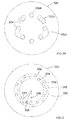
- the abrasive disc 100 is a universal abrasive disc that may be utilized with sander units having different numbers of exhaust holes, in particular sander units having either five or eight exhaust holes.
- the abrasive disc 100 includes a plurality of exhaust apertures.
- the abrasive disc 100 includes one or two substantially circular apertures 102a, at least two apertures 102b elongated along a single axis 112, and at least two boomerang-shaped apertures 102c elongated along two axes 114, 116 arranged at an angle ⁇ .
- apertures 102c each include two elongated portions connected to each other at an angle ⁇ .
- the arrangement of the apertures 102 allows for the abrasive disc 100 to be used with sander units having either five or eight exhaust holes.
- the circular apertures 102a are symmetrically arranged with respect to the axis of symmetry 122.
- the elongated apertures 102b and the boomerang-shaped apertures 102c are symmetrically arranged with respect to the axis of symmetry 120.
- Figs. 2A and 2B depict the arrangements of the abrasive disc 100 over a flat surface of sander units having five and eight holes, respectively.
- the apertures 102 of the abrasive disc 100 at least partially overlap the exhaust holes 202 of a five-hole sander unit.
- the apertures 102 of the abrasive disc 100 at least partially overlap the exhaust holes 204 of an eight-hole sander unit.
- Other annular arrangements of the abrasive disc 100 over the flat surface of the sanding unit are possible to achieve sufficient exposure of the exhaust holes.
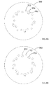
- Fig. 3 depicts an abrasive disc 300 according to an alternative embodiment of the invention.
- the abrasive disc 300 includes a first annular ring of apertures 302 and a second annular ring of apertures 304.
- the first and second annular rings shown by dotted lines in this figure are not actual patterns visible on the disc and are only used in these figures to illustrate the relative positions of the apertures 302 and 403 within the abrasive disc 300.
- the apertures 302 of the first annular ring are arranged such that the inner circumference 316 and outer circumference 318 of the first annular ring are respectively disposed within distances 306 and 308 from the center of the abrasive disc 300.
- the apertures 304 of the second annular ring are arranged such that the inner circumference 318 and outer circumference 320 of the second annular ring are respectively disposed within distances 308 and 310 from the center of the abrasive disc 300.
- the outer circumference of the inner annular ring and the inner circumference of the second annular substantially overlap.
- the same number of apertures 302, 304 may be arranged within each of the first and second annular rings, although other variations of the number of apertures within each annular ring are within the scope of the invention.
- nine apertures 302 and nine apertures 304 are provided within the first and second annular rings, respectively.
- the apertures 302, 304 within each ring are equidistance, although in alternative embodiments the distance between respective apertures may vary to optimize the area of the sander unit holes covered by the abrasive disc 300 apertures 302, 304.
- additional rings of apertures may be provided in parallel to the first and second annular rings.
- a third annular ring of apertures may be provided outside the second ring.
- the third annular ring includes apertures of equal size as apertures 302, 304, although in some embodiments the third annular ring may include larger or smaller apertures.
- the inner circumference of the third ring may overlap the outer circumference of the second annular ring, although in some embodiments the third annular ring may be disposed farther from the center of the disc.
- Figs. 4A and 4B depict the arrangements of the abrasive disc 300 over a flat surface of sander units having five and eight holes, respectively.
- the apertures 302 and 304 of the abrasive disc 300 at least partially overlap the exhaust holes 402 of a five-hole sander unit.
- the apertures 302 and 304 of the abrasive disc 300 at least partially overlap exhaust holes 404 of an eight-hole sander unit.
- the abrasive disc 300 it is possible to arrange the abrasive disc 300 over the flat surface of the sander unit in different annular orientations so as to provide adequate alignment between the apertures 302, 304 of the abrasive disc and the exhaust holes 402, 404 of the sanding unit.
- the annular arrangement of the abrasive disc 300 is not completely independent of the location of the exhaust holes (i.e., in some annular arrangement, one or more holes may not be partially exposed), it provides the user with many a lot of flexibility for placing the disc on the sander in a way that a substantial portion of the exhaust holes 402, 404 are exposed through the apertures 302, 304.
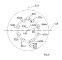
- Fig. 5 depicts an abrasive disc 500 according to a third embodiment of the invention.
- the abrasive disc 500 includes multiple circular apertures arranged at different distances from the center 520 of the disc 500.
- four apertures 502a-d are positioned on a first circle 542 having a radius 532 (i.e., at a distance 532 from the center 520), four apertures 504a-d on a second circle 544 having a radius 534 (i.e., at a distance 534 from the center), and a single aperture 506 on a third circle 546 (i.e., at a distance 536 from the center 520).
- Apertures 502a-d and 504a-d are alternatively arranged around the center 520.
- the disc is symmetric around the axis of symmetry 522 through the aperture 506.
- apertures 502a and 502d, apertures 502b and 502c, apertures 504a and 504d, and apertures 504b and 504c are arranged in symmetry around the axis of symmetry 522.
- the aforementioned apertures are not in symmetry around the axis 524.
- abrasive disc of this invention can be adapted for use with sanding units and dust extraction systems having different numbers and configurations of exhaust holes.
- Other size mounting surfaces are also available on the market which may also provide the need for universal abrasive discs.
Landscapes
- Engineering & Computer Science (AREA)
- Mechanical Engineering (AREA)
- Polishing Bodies And Polishing Tools (AREA)
- Grinding-Machine Dressing And Accessory Apparatuses (AREA)
Abstract
Description
- This application claims the benefit of prior filed co-pending
U.S. Provisional Application No. 61/389,921, filed October 5, 2010 - The present invention relates to abrasive discs, and more particularly to a universal abrasive disc for use with orbital sanders having different numbers of exhaust holes.
- Many orbital or random orbit sanders include a vacuum extraction system, which may be integrally or detachably mounted to the sander. A flat surface of the sander units are often provided with a number of exhaust holes that are connected to the vacuum extraction system. The vacuum extraction system sucks in dust and debris through these exhaust holes while the sander unit is in use. Most sander units are provided with either five or eight exhaust holes. Conventional abrasive disc that are attached to the flat surface of the sander unit are also provided with either five or eight apertures that can be aligned with the exhaust holes of the sander unit. Accordingly, different types of abrasive discs are required to meet the number of holes provided on the sander unit. What is needed is a universal abrasive disc compatible with different sander unites having different numbers of exhaust holes.
- In order to overcome these and other objective, a universal abrasive disc is provided that can be mounted on a surface of an orbital sander having either five or eight dust extraction holes. The abrasive disc includes apertures arrangeable to at least partially overlap each of the five or eight dust extraction holes of the orbital sander.
- In one embodiment, the abrasive disc includes at least one aperture having two elongated portions connected to each other at one end, the elongated portions extending along two axes forming an angle of curvature θ of between 90° to 150°. The aperture is arranged such that the angle θ is facing the center of the abrasive disc. In other words, the center of the abrasive disc is inside the angle θ. The disc may also include one or more substantially circular-shaped aperture and one or more elongated aperture that are elongated along a single axis (i.e., include no angle of curvature). The elongated apertures may be arranged in symmetry along a vertical axis of symmetry intersecting the center of the abrasive disc. The substantially circular-shaped apertures may be arranged in symmetry along a horizontal axis of symmetry intersecting the center of the abrasive disc.
- In an alternative embodiment, the apertures of the disc are disposed within a first ring and a second ring, where the two rings have the same center as the abrasive disc and each have a width equal to a diameter of the apertures. The rings are arranged such that an outer circumference of the first ring substantially overlaps an inner circumference of the second ring. In an embodiment, an equal number of apertures are disposed equidistantly within the first and the second rings respectively. Also, in an embodiment, each aperture within the first ring has the same distance from its two closest apertures within the second ring, and vice versa.
- In yet another embodiment, the apertures of the disc include a first group of apertures arranged at a first distance from the center of the abrasive disc, a second group of apertures arranged at a second distance from the center of the abrasive disc, and a third aperture arranged at a third distance from the center of the abrasive disc. Each of the first and second apertures is arranged symmetrically with respect to a corresponding aperture along a first axis of symmetry that intersects the center of the third aperture and the center of the abrasive disc. However, in an embodiment, none of the first and second apertures is arranged symmetrically with respect to a corresponding aperture along a second axis located perpendicularly to the first axis of symmetry through the center of the abrasive disc.
- For a more complete understanding of the invention, its objects and advantages, reference may be had to the following specification and to the accompanying drawings.
- The drawings described herein are for illustration purposes only and are not intended to limit the scope of this disclosure in any way:
-
FIG. 1 depicts a perspective view of an abrasive disc, according to a first embodiment of this disclosure; -
FIGS. 2A and2B depict perspective views of the abrasive disc of the first embodiment as used with a five hole and an eight hole sander unit, according to an embodiment of the invention; -
FIG. 3 depicts a perspective view of an abrasive disc, according to a second embodiment of this disclosure; -
FIGS. 4A and 4B depict perspective views of the abrasive disc of the second embodiment as used with a five hole and an eight hole sander unit, according to an embodiment of the invention; and -
FIG. 5 depicts a perspective view of an abrasive disc, according to a third embodiment of this disclosure. - With reference to the
Fig. 1 , anabrasive disc 100 according to a first embodiment of the invention is depicted. Theabrasive disc 100 is a universal abrasive disc that may be utilized with sander units having different numbers of exhaust holes, in particular sander units having either five or eight exhaust holes. - As shown in
Fig. 1 , theabrasive disc 100 includes a plurality of exhaust apertures. In the exemplary embodiment, theabrasive disc 100 includes one or two substantiallycircular apertures 102a, at least twoapertures 102b elongated along asingle axis 112, and at least two boomerang-shaped apertures 102c elongated along twoaxes apertures 102c each include two elongated portions connected to each other at an angle θ. The arrangement of the apertures 102 allows for theabrasive disc 100 to be used with sander units having either five or eight exhaust holes. Thecircular apertures 102a are symmetrically arranged with respect to the axis ofsymmetry 122. Theelongated apertures 102b and the boomerang-shaped apertures 102c are symmetrically arranged with respect to the axis ofsymmetry 120. -
Figs. 2A and2B depict the arrangements of theabrasive disc 100 over a flat surface of sander units having five and eight holes, respectively. As shown inFig. 2A , the apertures 102 of theabrasive disc 100 at least partially overlap theexhaust holes 202 of a five-hole sander unit. Similarly, as shown inFig. 2B , the apertures 102 of theabrasive disc 100 at least partially overlap theexhaust holes 204 of an eight-hole sander unit. Other annular arrangements of theabrasive disc 100 over the flat surface of the sanding unit are possible to achieve sufficient exposure of the exhaust holes. -
Fig. 3 depicts anabrasive disc 300 according to an alternative embodiment of the invention. As shown inFig. 3 , theabrasive disc 300 includes a first annular ring ofapertures 302 and a second annular ring ofapertures 304. The first and second annular rings shown by dotted lines in this figure are not actual patterns visible on the disc and are only used in these figures to illustrate the relative positions of theapertures 302 and 403 within theabrasive disc 300. Theapertures 302 of the first annular ring are arranged such that theinner circumference 316 andouter circumference 318 of the first annular ring are respectively disposed withindistances abrasive disc 300. Theapertures 304 of the second annular ring are arranged such that theinner circumference 318 andouter circumference 320 of the second annular ring are respectively disposed withindistances abrasive disc 300. Thus, the outer circumference of the inner annular ring and the inner circumference of the second annular substantially overlap. - In an exemplary embodiment, the same number of
apertures Fig. 3 , nineapertures 302 and nineapertures 304 are provided within the first and second annular rings, respectively. Furthermore, in the exemplary embodiment, theapertures abrasive disc 300apertures - In addition, in some embodiments, additional rings of apertures may be provided in parallel to the first and second annular rings. For example, a third annular ring of apertures may be provided outside the second ring. The third annular ring includes apertures of equal size as
apertures -
Figs. 4A and 4B depict the arrangements of theabrasive disc 300 over a flat surface of sander units having five and eight holes, respectively. As shown inFig. 4A , theapertures abrasive disc 300 at least partially overlap theexhaust holes 402 of a five-hole sander unit. Similarly, as shown inFig. 4B , theapertures abrasive disc 300 at least partially overlapexhaust holes 404 of an eight-hole sander unit. As can be seen in these figures, it is possible to arrange theabrasive disc 300 over the flat surface of the sander unit in different annular orientations so as to provide adequate alignment between theapertures abrasive disc 300 is not completely independent of the location of the exhaust holes (i.e., in some annular arrangement, one or more holes may not be partially exposed), it provides the user with many a lot of flexibility for placing the disc on the sander in a way that a substantial portion of the exhaust holes 402, 404 are exposed through theapertures -
Fig. 5 depicts an abrasive disc 500 according to a third embodiment of the invention. As shown inFig. 5 , the abrasive disc 500 includes multiple circular apertures arranged at different distances from thecenter 520 of the disc 500. In the exemplary embodiment, fourapertures 502a-d are positioned on afirst circle 542 having a radius 532 (i.e., at adistance 532 from the center 520), fourapertures 504a-d on asecond circle 544 having a radius 534 (i.e., at adistance 534 from the center), and asingle aperture 506 on a third circle 546 (i.e., at adistance 536 from the center 520).Apertures 502a-d and 504a-d are alternatively arranged around thecenter 520. The disc is symmetric around the axis ofsymmetry 522 through theaperture 506. Specifically,apertures apertures apertures apertures symmetry 522. In an embodiment, the aforementioned apertures are not in symmetry around theaxis 524. - While the this invention is illustrated using conventional five and eight hole sander units, it is readily understood that the abrasive disc of this invention can be adapted for use with sanding units and dust extraction systems having different numbers and configurations of exhaust holes. Other size mounting surfaces are also available on the market which may also provide the need for universal abrasive discs.
- Although this invention has been described with reference to preferred embodiments, workers skilled in the art will recognize that changes may be made in form and detail without departing from the spirit and scope of the invention. In addition, the invention is not to be taken as limited to all of the details thereof as modifications and variations thereof may be made without departing from the spirit or scope of the invention.
Claims (13)
- An abrasive disc adapted to mount on a surface of a sander having either five or eight dust extraction holes, the disc comprising a plurality of equally-sized apertures arrangeable to at least partially overlap each of the five or eight dust extraction holes of the sander, the plurality of apertures comprising a first plurality of apertures disposed within a first annular ring and a second plurality of apertures disposed within a second annular ring, the first and the second annular rings each having the same center as the abrasive disc and each having a width equal to a diameter of each aperture, wherein an outer circumference of the first annular ring substantially overlaps an inner circumference of the second annular ring.
- The abrasive disc of claim 1, wherein each of the first and second plurality of apertures is disposed equidistantly within the first and the second annular rings, respectively.
- The abrasive disc of claim 2, wherein each of the first plurality of apertures is disposed within the same distance of the two nearest apertures of the second plurality of apertures.
- The abrasive disc of claim 1, wherein an equal number of apertures are disposed within the first and the second annular rings.
- The abrasive disc of claim 1, wherein at least nine apertures are disposed within each of the first and the second annular rings.
- The abrasive disc of claim 1, further comprising a third plurality of apertures disposed within a third annular ring having the same center as the abrasive disc and having a width equal to the diameter of the third apertures.
- An abrasive disc adapted to mount on a surface of a sander having either five or eight dust extraction holes, the disc comprising a plurality of apertures arrangeable to at least partially overlap each of the five or eight dust extraction holes of the sander, the plurality of apertures comprising a first plurality of apertures arranged at a first distance from the center of the abrasive disc, a second plurality of apertures arranged at a second distance from the center of the abrasive disc, and a third aperture arranged at a third distance from the center of the abrasive disc, wherein each of the first and second apertures is arranged symmetrically with respect to a corresponding aperture along a first axis of symmetry that intersects the center of the third aperture and the center of the abrasive disc.
- The abrasive disc of claim 7, wherein none of the first and second plurality of apertures is arranged symmetrically with respect to a corresponding aperture along a second axis located perpendicularly to the first axis of symmetry through the center of the abrasive disc.
- The abrasive disc of claim 7, wherein each of the first and second plurality of apertures comprises four apertures.
- The abrasive disc of claim 7, wherein each of the first and second plurality of apertures and the third aperture is substantially circular-shaped.
- The abrasive disc of claim 7, wherein two apertures of the first plurality of apertures are arranged in close proximity to the third aperture.
- The abrasive disc of claim 7, wherein the first and second plurality of apertures are alternatively arranged around the center of the abrasive disc.
- The abrasive disc of claim 7, wherein the plurality of apertures are equally-sized.
Applications Claiming Priority (2)
| Application Number | Priority Date | Filing Date | Title |
|---|---|---|---|
| US38992110P | 2010-10-05 | 2010-10-05 | |
| EP11184013.8A EP2439019A3 (en) | 2010-10-05 | 2011-10-05 | Universal Abrasive Disc |
Related Parent Applications (1)
| Application Number | Title | Priority Date | Filing Date |
|---|---|---|---|
| EP11184013.8A Division EP2439019A3 (en) | 2010-10-05 | 2011-10-05 | Universal Abrasive Disc |
Publications (1)
| Publication Number | Publication Date |
|---|---|
| EP2939788A1 true EP2939788A1 (en) | 2015-11-04 |
Family
ID=44993471
Family Applications (2)
| Application Number | Title | Priority Date | Filing Date |
|---|---|---|---|
| EP11184013.8A Withdrawn EP2439019A3 (en) | 2010-10-05 | 2011-10-05 | Universal Abrasive Disc |
| EP15165665.9A Withdrawn EP2939788A1 (en) | 2010-10-05 | 2011-10-05 | Universal abrasive disc |
Family Applications Before (1)
| Application Number | Title | Priority Date | Filing Date |
|---|---|---|---|
| EP11184013.8A Withdrawn EP2439019A3 (en) | 2010-10-05 | 2011-10-05 | Universal Abrasive Disc |
Country Status (2)
| Country | Link |
|---|---|
| US (1) | US20120083193A1 (en) |
| EP (2) | EP2439019A3 (en) |
Families Citing this family (2)
| Publication number | Priority date | Publication date | Assignee | Title |
|---|---|---|---|---|
| US20150202743A1 (en) * | 2014-01-21 | 2015-07-23 | Cherif Morcos | Universal fit sanding pad for random orbital sanders |
| CN113442028B (en) * | 2021-06-29 | 2023-03-14 | 中国农业科学院兰州畜牧与兽药研究所 | A grinding device for yak horns |
Citations (9)
| Publication number | Priority date | Publication date | Assignee | Title |
|---|---|---|---|---|
| US5020283A (en) * | 1990-01-22 | 1991-06-04 | Micron Technology, Inc. | Polishing pad with uniform abrasion |
| US5989112A (en) * | 1998-05-11 | 1999-11-23 | Norton Company | Universal abrasive disc |
| US20030032383A1 (en) * | 2001-08-10 | 2003-02-13 | Nelson Eric W. | Abrasive article with universal hole pattern |
| US20070077867A1 (en) * | 2005-10-03 | 2007-04-05 | Masaomi Nakahata | Polishing pad and polishing apparatus |
| US20070243803A1 (en) * | 2006-04-14 | 2007-10-18 | 3M Innovative Properties Company | Abrasive tool for collecting dust |
| WO2007143400A2 (en) * | 2006-05-30 | 2007-12-13 | 3M Innovative Properties Company | Abrading article comprising a slotted abrasive disc and a back-up pad |
| US20080081546A1 (en) * | 2006-09-29 | 2008-04-03 | 3M Innovative Properties Company | Dust vacuuming abrasive tool |
| WO2008115663A1 (en) * | 2007-03-20 | 2008-09-25 | 3M Innovative Properties Company | Abrasive article and method of making and using the same |
| WO2009088772A2 (en) * | 2007-12-31 | 2009-07-16 | Saint-Gobain Abrasives, Inc. | Interface pad for use between an abrasive article and a support tool |
Family Cites Families (8)
| Publication number | Priority date | Publication date | Assignee | Title |
|---|---|---|---|---|
| US3204371A (en) * | 1963-02-04 | 1965-09-07 | Bay State Abrasive Products Co | Mounting insert for resinoid cup grinding wheels |
| US3827194A (en) * | 1972-08-21 | 1974-08-06 | A Hutchins | Piercing of suction holes in sanding discs |
| US4287685A (en) * | 1978-12-08 | 1981-09-08 | Miksa Marton | Pad assembly for vacuum rotary sander |
| US5115796A (en) * | 1987-11-09 | 1992-05-26 | Schweickhardt Karl B | Diamond abrasive saw blade and method of dry sawing concrete |
| FR2750354B1 (en) * | 1996-06-28 | 1998-08-07 | Lam Plan Sa | POLISHING DISC HOLDER AND POLISHING METHOD |
| DE19707445A1 (en) * | 1997-02-25 | 1998-08-27 | Hilti Ag | Cup-shaped grinding wheel |
| DE10047543A1 (en) * | 2000-09-22 | 2002-04-11 | Bosch Gmbh Robert | Abrasives and abrasives for an electrical grinding tool and electrical grinding tool |
| DE10352501A1 (en) * | 2003-11-11 | 2005-06-02 | Robert Bosch Gmbh | Sanding plate holder for a hand-held electric grinding tool |
-
2011
- 2011-10-05 EP EP11184013.8A patent/EP2439019A3/en not_active Withdrawn
- 2011-10-05 US US13/253,334 patent/US20120083193A1/en not_active Abandoned
- 2011-10-05 EP EP15165665.9A patent/EP2939788A1/en not_active Withdrawn
Patent Citations (9)
| Publication number | Priority date | Publication date | Assignee | Title |
|---|---|---|---|---|
| US5020283A (en) * | 1990-01-22 | 1991-06-04 | Micron Technology, Inc. | Polishing pad with uniform abrasion |
| US5989112A (en) * | 1998-05-11 | 1999-11-23 | Norton Company | Universal abrasive disc |
| US20030032383A1 (en) * | 2001-08-10 | 2003-02-13 | Nelson Eric W. | Abrasive article with universal hole pattern |
| US20070077867A1 (en) * | 2005-10-03 | 2007-04-05 | Masaomi Nakahata | Polishing pad and polishing apparatus |
| US20070243803A1 (en) * | 2006-04-14 | 2007-10-18 | 3M Innovative Properties Company | Abrasive tool for collecting dust |
| WO2007143400A2 (en) * | 2006-05-30 | 2007-12-13 | 3M Innovative Properties Company | Abrading article comprising a slotted abrasive disc and a back-up pad |
| US20080081546A1 (en) * | 2006-09-29 | 2008-04-03 | 3M Innovative Properties Company | Dust vacuuming abrasive tool |
| WO2008115663A1 (en) * | 2007-03-20 | 2008-09-25 | 3M Innovative Properties Company | Abrasive article and method of making and using the same |
| WO2009088772A2 (en) * | 2007-12-31 | 2009-07-16 | Saint-Gobain Abrasives, Inc. | Interface pad for use between an abrasive article and a support tool |
Also Published As
| Publication number | Publication date |
|---|---|
| EP2439019A3 (en) | 2014-06-18 |
| US20120083193A1 (en) | 2012-04-05 |
| EP2439019A2 (en) | 2012-04-11 |
Similar Documents
| Publication | Publication Date | Title |
|---|---|---|
| US8960339B2 (en) | Mecanum wheel | |
| US10335917B2 (en) | Pad for supporting abrasive disc | |
| US9676231B2 (en) | Aircraft wheel rim with removable flange | |
| RU2007117362A (en) | FAN GRINDING CIRCLE | |
| JP2010509080A5 (en) | ||
| EP2439019A2 (en) | Universal Abrasive Disc | |
| US8627741B2 (en) | Process turning disc, a robot arm comprising a process turning disc, a robot and a use of a process turning disc | |
| US8087855B1 (en) | Multi-function drill press system | |
| US11167361B2 (en) | Cutting insert and cutting tool | |
| JP2005118987A5 (en) | ||
| US20140338790A1 (en) | Stump Cutting Apparatus | |
| JP5722367B2 (en) | Centrifugal blower | |
| CN206765702U (en) | Omni-directional wheel and the robot with the omni-directional wheel | |
| US20120122384A1 (en) | Abrasive disc with universal hole pattern | |
| JP6184032B2 (en) | Polishing body for screw shaft and its segment | |
| CN109689296A (en) | Supporting mass for grinding tool | |
| JP2019203884A5 (en) | ||
| CN210363186U (en) | Omnidirectional wheel | |
| US9457617B2 (en) | Vehicular wheel | |
| CN211859896U (en) | Anti-wire-jumping winding template for automobile driving motor | |
| TWI573665B (en) | Grinding stone and grinding equipment | |
| CN207064310U (en) | A kind of motor of fan and its application | |
| JP2015128515A (en) | Variable pipe device for game media distribution pipe | |
| CN108916359B (en) | Modularized flexible rack | |
| JPH056063Y2 (en) |
Legal Events
| Date | Code | Title | Description |
|---|---|---|---|
| PUAI | Public reference made under article 153(3) epc to a published international application that has entered the european phase |
Free format text: ORIGINAL CODE: 0009012 |
|
| 17P | Request for examination filed |
Effective date: 20150429 |
|
| AC | Divisional application: reference to earlier application |
Ref document number: 2439019 Country of ref document: EP Kind code of ref document: P |
|
| AK | Designated contracting states |
Kind code of ref document: A1 Designated state(s): AL AT BE BG CH CY CZ DE DK EE ES FI FR GB GR HR HU IE IS IT LI LT LU LV MC MK MT NL NO PL PT RO RS SE SI SK SM TR |
|
| STAA | Information on the status of an ep patent application or granted ep patent |
Free format text: STATUS: EXAMINATION IS IN PROGRESS |
|
| 17Q | First examination report despatched |
Effective date: 20170322 |
|
| STAA | Information on the status of an ep patent application or granted ep patent |
Free format text: STATUS: THE APPLICATION IS DEEMED TO BE WITHDRAWN |
|
| 18D | Application deemed to be withdrawn |
Effective date: 20171003 |