EP2939707A1 - Medical apparatus - Google Patents
Medical apparatus Download PDFInfo
- Publication number
- EP2939707A1 EP2939707A1 EP15165014.0A EP15165014A EP2939707A1 EP 2939707 A1 EP2939707 A1 EP 2939707A1 EP 15165014 A EP15165014 A EP 15165014A EP 2939707 A1 EP2939707 A1 EP 2939707A1
- Authority
- EP
- European Patent Office
- Prior art keywords
- control unit
- unit
- power supply
- monitoring
- medical apparatus
- Prior art date
- Legal status (The legal status is an assumption and is not a legal conclusion. Google has not performed a legal analysis and makes no representation as to the accuracy of the status listed.)
- Granted
Links
Images



Classifications
-
- A—HUMAN NECESSITIES
- A61—MEDICAL OR VETERINARY SCIENCE; HYGIENE
- A61N—ELECTROTHERAPY; MAGNETOTHERAPY; RADIATION THERAPY; ULTRASOUND THERAPY
- A61N1/00—Electrotherapy; Circuits therefor
- A61N1/18—Applying electric currents by contact electrodes
- A61N1/32—Applying electric currents by contact electrodes alternating or intermittent currents
- A61N1/38—Applying electric currents by contact electrodes alternating or intermittent currents for producing shock effects
- A61N1/39—Heart defibrillators
- A61N1/3925—Monitoring; Protecting
- A61N1/3931—Protecting, e.g. back-up systems
-
- A—HUMAN NECESSITIES
- A61—MEDICAL OR VETERINARY SCIENCE; HYGIENE
- A61N—ELECTROTHERAPY; MAGNETOTHERAPY; RADIATION THERAPY; ULTRASOUND THERAPY
- A61N1/00—Electrotherapy; Circuits therefor
- A61N1/18—Applying electric currents by contact electrodes
- A61N1/32—Applying electric currents by contact electrodes alternating or intermittent currents
- A61N1/38—Applying electric currents by contact electrodes alternating or intermittent currents for producing shock effects
- A61N1/39—Heart defibrillators
- A61N1/3975—Power supply
Definitions
- the present invention relates to a medical apparatus and, more particularly, to a medical apparatus having an abnormality monitoring mechanism.
- an AED Automatic External Defibrillator
- An AED applies a strong electric shock to the heart that has stopped due to ventricular fibrillation to remove the spasm of the heart muscle. Since the operation of an AED is fatal to a rescuee, a failure that occurs in an AED needs to be recognized immediately.
- a general AED is provided with a status indicator on the surface of the cabinet. Upon detecting an abnormality (failure) internally, the AED indicates an abnormal state on the status indicator.
- PTL 1 discloses the related art having an advanced failure detection technique.
- the defibrillator disclosed in PTL 1 incorporates a self-test system.
- This automatic self-test system automatically carries out a function test and calibration verification inspection in response to a test signal to be generated periodically. Then, the self-test system outputs the test result visually and audibly. Accordingly, the state of the defibrillation can be determined and reported automatically without user intervention.
- an AED has a self-check function and, when detecting an abnormality, indicates it on the status indicator.
- An indicator control unit processing unit for changing the indication of the status indicator
- the indicator control unit may not control the status indicator appropriately. Accordingly, the failure cannot be reported to the user. That is, the abnormality monitoring function of a conventional medical apparatus is insufficient and an abnormal state may not be reported to the user appropriately.
- the above problem is not limited to an AED and common to various types of medical apparatuses having a status indicator (display unit).
- the invention addresses the above problems with a main object of providing a medical apparatus that appropriately indicates an abnormal state to the user.
- a medical apparatus includes an output unit outputting whether the medical apparatus is in an abnormal state, a first control unit controlling the medical apparatus, and a monitoring unit detecting an operation abnormality in the first control unit, in which the first control unit performs operation monitoring of the monitoring unit and, when detecting an operation abnormality, causes the output unit to output an abnormal state and the monitoring unit performs operation monitoring of the first control unit and, when detecting an operation abnormality, causes the output unit to output an abnormal state.
- the first control unit and the monitoring unit monitor the operation each other and, when detecting an operation abnormality, cause the output unit to output the abnormality. Since the first control unit and the monitoring unit monitor the operation each other, an operation abnormality can be detected more accurately as compared with a configuration in which one-way operation monitoring is performed. Since an operation abnormality can be detected accurately, an abnormal state can be reported immediately to the user of the medical apparatus.
- a medical apparatus capable of appropriately reporting an abnormal state of an apparatus to the user.
- a medical apparatus will be described with reference to the drawings.
- a medical apparatus including batteries (first battery and second battery) capable of continuously supplying power and an attachable and detachable battery (removal battery) is mainly assumed.
- this medical apparatus is assumed to be an AED (Automated External Defibrillator).
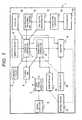
- Fig. 1 is a block diagram illustrating the structure of an AED 1 (medical apparatus) according to the embodiment.
- the AED 1 includes a plurality of batteries: an internal battery 16 (first battery), an internal battery 17 (second battery), and a power supply unit 2 (removable battery).
- the AED 1 includes the power supply unit 2 (removable battery), a DC/DC power supply unit 3, a storage unit 4, a communication unit 5, a manipulating unit 6, an operation control unit 7 (second control unit), a power supply control unit 8 (first control unit), an indicator 9 (which is a display unit and also an aspect of the output unit), a voice unit 10, an electrocardiogram signal amplifying unit 11, a high voltage generating unit 12, a high voltage capacitor 13, a pad connector 14, a monitoring unit 15, the internal battery 16 (first battery), and the internal battery 17 (second battery) .
- the power supply unit 2 (removable battery) is a battery attachable to or detachable from the AED 1 and, for example, a lithium primary battery.
- the power supply unit 2 is a battery that has a larger capacity and a larger energy density than the internal battery 16 (first battery) and the internal battery 17 (second battery), which will be described later.
- the power supply unit 2 is preferably operable for several years without being replaced.
- the power supply unit 2 supplies power to processing units in the AED 1 via the DC/DC power supply unit 3.
- the DC/DC power supply unit 3 converts a power voltage supplied from the power supply unit 2 to voltages necessary for circuits in the AED 1 and supplies the converted voltages to the circuits.
- the DC/DC power supply unit 3 performs voltage conversion using a technique of a switching regulator or series regulator.
- the storage unit 4 stores programs necessary for operation of the AED 1, voice data, adjustment values specific to the medical apparatus, electrocardiogram data during rescue, and so on.
- the storage unit 4 is a secondary storage device such as, for example, a hard disk drive.
- the communication unit 5 is a communication interface for transmitting electrocardiogram data during rescue and so on stored in the storage unit 4 to any computers.
- the manipulating unit 6 is an operation interface including a power button and shock button provided on a surface of the cabinet of the AED 1. The rescuer applies an electric shock to the rescuee by manipulating the manipulating unit 6.
- the operation control unit 7 controls the medical apparatus (that is, the AED 1). More specifically, the operation control unit 7 performs various types of operation control such as control of energy charging and discharging, sequence control, electrocardiogram analysis, and voice output control.
- the operation control unit 7 includes a CPU (Central Processing Unit), a gate array, an analog-to-digital converter, and so on.
- the operation control unit 7 also performs the operation monitoring of the power supply control unit 8 which will be described later and, when detecting an operation abnormality of the power supply control unit 8, performs control so that the indicator 9 indicates an abnormal state. Details on the operation monitoring will be described later with reference to Fig. 3 and other drawings.
- the power supply control unit 8 (first control unit) is operable by receiving power from the internal battery 16 (which is not detachable from the AED 1 and capable of continuously supplying power).
- the power supply control unit 8 may be operated by receiving power from the power supply unit 2 instead of the internal battery 16. This enables the power supply control unit 8 to be operated by receiving power from a stable power supply source (power supply unit 2) with larger capacity.
- the power supply control unit 8 controls the medical apparatus (that is, the AED 1). More specifically, the power supply control unit 8 controls power supplied from the power supply unit 2, which is used as the main battery during a periodical inspection or the like. In addition, the power supply control unit 8 performs the operation monitoring of the operation control unit 7 and, when detecting an operation abnormality, switches the indication of the indicator 9. In addition, the power supply control unit 8 performs the operation monitoring of the monitoring unit 15 and, when detecting an operation abnormality, switches the indication of the indicator 9. The operation monitoring by the power supply control unit 8 will be described later with reference to Figs. 3 to 5 .
- Each of the operation control unit 7 (second control unit) and the power supply control unit 8 (first control unit) has a CPU (Central Processing Unit) and reads various types of programs from the storage unit 4 to execute them.
- CPU Central Processing Unit
- the indicator 9 (which is a display unit and also an aspect of the output unit) indicates the operating state of the AED 1.
- the indicator 9 reports, to the operator, the operating state of the AED 1 by, for example, the colors of lamps.
- the indicator 9 operates by receiving power from the power supply unit 2.
- the power supply unit 2 cannot supply power (for example, the power supply unit 2 is removed from the AED 1), the indicator 9 operates by receiving power from the internal battery 16 or the internal battery 17.
- the voice unit 10 outputs a voice (an instruction for the operator or a buzzer sound during detection of an abnormality) depending on control by the operation control unit 7.
- the electrocardiogram signal amplifying unit 11 filters and amplifies an electrocardiogram signal captured through a defibrillation pad (not illustrated) connected to the pad connector 14.
- the high voltage generating unit 12 charges or discharges energy used for defibrillation based on control by the operation control unit 7.
- the energy for defibrillation is charged in the high voltage capacitor 13.
- the pad connector 14 is an interface to the defibrillation pad (not illustrated) that makes contact with the body of the rescuee.
- the monitoring unit 15 performs the operation monitoring of the power supply control unit 8 and, when detecting an operation abnormality, performs control so that the indicator 9 indicates an abnormality notification.
- the method for detecting an operation abnormality will be described later with reference to Fig. 4 .
- the monitoring unit 15 When the power supply unit 2 with a large capacity can supply power, the monitoring unit 15 operates by receiving power from the power supply unit 2. When the power supply unit 2 cannot supply power (for example, the power supply unit 2 is removed from the AED 1), the monitoring unit 15 operates by receiving power from the internal battery 17.
- the internal battery 16 is a battery (not removed from the AED 1) in the AED 1 capable of continuously supplying power.
- the internal battery 16 supplies power to the power supply control unit 8 and the indicator 9.
- the internal battery 17 is a battery (not removed from the AED 1) in the AED 1 capable of continuously supplying power.
- the internal battery 17 supplies power to the indicator 9 and the monitoring unit 15. That is, in the embodiment, the internal battery 16 and the internal battery 17 constitute a continuous power supply system.
- the communication unit 5, the voice unit 10, and the indicator 9 described above can be considered as output units that output an abnormal state within the AED 1.
- the communication unit 5 may report occurrence of an abnormality by email (illustrated in Fig. 2 , for example) to a predetermined address during detection of the abnormality.
- the destination address or the like only needs to be stored in the storage unit 4.
- the voice unit 10 may report an abnormal state using a voice output during detection of an abnormality.
- the indicator 9 reports an abnormal state using indication of lamps or the like on the cabinet when detecting an abnormality.
- These output units may operate at the same time to report an abnormal state.
- the voice unit 10 may perform a voice output indicating an abnormal state as soon as the indication of the indicator 9 is switched to an abnormal state.
- the indicator 9 can be operated by receiving power from the internal battery 16 or the internal battery 17, even when an abnormal state is detected at a timing at which power is not supplied from the power supply unit 2, an appropriate report can be issued. In the following description, the indicator 9 is assumed to output an abnormal state.
- the power supply unit 2 supplies power to the monitoring unit 15, the power supply control unit 8, and the operation control unit 7.
- the internal battery 16 supplies power to the power supply control unit 8.
- the internal battery 17 supplies power to the monitoring unit 15.
- the indicator 9 receives power from the internal battery 16 or the internal battery 17. This makes the monitoring unit 15, the power supply control unit 8, and the indicator 9 operable at all times.
- the monitoring unit 15 and the power supply control unit 8 monitor an operation abnormality each other and, when detecting an operation abnormality, switch the indication of the indicator 9.
- the power supply control unit 8 and the operation control unit 7 monitor an operation abnormality each other and, when detecting an operation abnormality, switch the indication of the indicator 9. Accordingly, when any of processing units is put in an abnormal state, the indicator 9 indicates the abnormal state. That is, in the AED 1, the processing units centering on the power supply control unit 8 monitor an operation abnormality each other and, when detecting an abnormality in any of them, the indicator 9 indicates the abnormality.
- the monitoring unit 15 periodically transmits a survival signal to the power supply control unit 8.
- the survival signal is a signal, having a small amount (number of bits) of information, that can be operated sufficiently in a power saving mode.
- the power supply control unit 8 determines that the monitoring unit 15 is normal. When not receiving the survival signal periodically from the monitoring unit 15 (that is, when not receiving the survival signal from the monitoring unit 15 again within a predetermined time after the previous reception of the survival signal), the power supply control unit 8 determines that the operation of the monitoring unit 15 is abnormal.
- the monitoring unit 15 determines that the power supply control unit 8 is normal.
- the monitoring unit 15 determines that the operation of the power supply control unit 8 is abnormal.
- the intervals at which the monitoring unit 15 and the power supply control unit 8 transmit the survival signal only need to be, for example, one second.
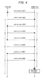
- the power supply control unit 8 Since the power supply control unit 8 has received survival signals S11, S13, S15, and S17 in the example in Fig. 4 , the power supply control unit 8 determines that the monitoring unit 15 is normal in this period. Similarly, the monitoring unit 15 has received survival signal S12, S14, S16, and S18, the monitoring unit 15 determines that the power supply control unit 8 is normal in this period. The power supply control unit 8 has not received the survival signal within a predetermined time (for example, one second) after reception of the survival signal S17. Accordingly, the power supply control unit 8 determines that an operation abnormality has occurred in the monitoring unit 15. Upon detecting an operation abnormality, the power supply control unit 8 switches the indication of the indicator 9 to an abnormal state.
- a predetermined time for example, one second
- the monitoring unit 15 and the power supply control unit 8 may be operated by the internal battery 16 or the internal battery 17 with a small power supply capacity. Since the capacity of the internal battery 16 or the internal battery 17 is limited generally, high power consumption use is not preferable. On the other hand, operation monitoring between the monitoring unit 15 and the power supply control unit 8 is performed only by reception acknowledgement of a survival signal having a small amount (number of bits) of information. In other wards, the monitoring unit 15 and the power supply control unit 8 detect an operation abnormality without performing communication requiring many interactions such as so-called ACK (acknowledgement) or NACK (negative acknowledgement). Accordingly, the power consumption of the internal battery 16 can be suppressed and the life of the entire apparatus can be increased.
- ACK acknowledgement
- NACK negative acknowledgement
- the power supply control unit 8 transmits response request information to the operation control unit 7.
- Response request information may include various types of information such as, for example, a serial number and requests of various computation results.
- the operation control unit 7 receives this response request information and transmits response information corresponding to the response request information to the power supply control unit 8.
- the power supply control unit 8 determines that an operation abnormality has occurred in the operation control unit 7.
- the operation control unit 7 detects an operation abnormality in the power supply control unit 8 using a similar method (transmission and reception of response request information and response information). Upon detecting an abnormality, the operation control unit 7 switches the indication of the indicator 9.
- the power supply control unit 8 has not received response information from the operation control unit 7 within a predetermined time after transmitting the response request information S25. Accordingly, the power supply control unit 8 determines that an operation abnormality has occurred in the operation control unit 7. When determining that an operation abnormality has occurred, the power supply control unit 8 switches the indication of the indicator 9 to an abnormal state.
- the operation control unit 7 is operated by receiving power from the power supply unit 2.
- the power supply control unit 8 is also operated by receiving power from the power supply unit 2 when the power supply unit 2 can supply power. That is, when abnormality detection is performed between these two processing units, it is expected that power is supplied from the power supply unit 2.
- operation abnormality detection can be performed in more detail. That is, the operation control unit 7 and the power supply control unit 8 can detect an operation abnormality based on not only whether transmission and reception have been performed, but also whether appropriate calculation or the like can be performed.
- the power supply control unit 8 (first control unit) and the monitoring unit 15 monitor the operation each other and, when detecting an operation abnormality, makes control so that the indicator 9 (aspect of the output unit performing abnormality output) performs an indication of an abnormality. Since the power supply control unit 8 and the monitoring unit 15 monitor the operation each other, an operation abnormality can be detected more accurately as compared with a configuration in which one-way operation monitoring is performed. Since an operation abnormality can be detected accurately, an abnormal state can be reported immediately to the user of the AED 1. This can reduce cases in which the AED 1 is left unrepaired even though the AED 1 has an abnormality internally.
- the power supply control unit 8, the indicator 9, and the monitoring unit 15 are operable by receiving power from the internal battery 16 and 17 capable of continuously supplying power. Accordingly, even when the power supply unit 2 is removed, the operation of the power supply control unit 8 can be monitored and, when an operation abnormality occurs, the indicator 9 can indicate the abnormality.
- the operation control unit 7 (second control unit) and the power supply control unit 8 (first control unit) also perform operation monitoring each other in the configuration. That is, the three processing units centering on the power supply control unit 8 perform monitoring each other ( Fig. 3 ), so that an operation abnormality can be detected and indicated
- the power supply control unit 8, the indicator 9, and the monitoring unit 15 are operable by the internal battery 16 (first battery) or the internal battery 17 (second battery) in the configuration. However, when the power supply unit 2 (removable battery) is available, the power supply control unit 8, the indicator 9, and the monitoring unit 15 are operated by receiving power from the power supply unit 2. When both the internal batteries 16 and 17 and the power supply unit 2 can be used, the power supply unit 2 with a larger capacity is used preferentially to prolong the battery life of the entire apparatus.
- operation monitoring between the power supply control unit 8 and the monitoring unit 15 is performed preferably based on whether a survival signal with a small amount of information (number of bits) has been received ( Fig. 4 ).
- the invention can be considered as follows.
- the AED 1 according to the embodiment has the monitoring unit 15 that is not present in the conventional configuration.
- the monitoring unit 15 is operated by a continuous power supply system and monitors the power supply control unit 8. That is, the AED 1 according to the embodiment has, in the continuous power supply system, a mechanism (monitoring unit 15) for monitoring an operation abnormality. Accordingly, even when the power supply unit 2 is removed, an operation abnormality can be detected.
- the power supply control unit 8 monitors an operation abnormality in monitoring unit 15, abnormality detection can be performed more accurately. This can reduce cases in which the AED 1 is left unrepaired even though the AED 1 has an abnormality internally.
- the monitoring unit 15 and the power supply control unit 8 can also receive power from the power supply unit 2, but each of these processing units may receive power from only one power supply source.
- the indicator 9 may indicate an abnormal state using characters instead of lamps.
- the power supply control unit 8 and the operation control unit 7 perform operation monitoring each other. However, even when at least one of the control units monitors the other, more sufficient effects can be expected than in the conventional configuration.
- both the power supply control unit 8 and the monitoring unit 15 can use both the power supply unit 2 and the internal battery 16, but the invention is not limited to the configuration and sufficient effects can be expected even when at least one of the power supply control unit 8 and the monitoring unit 15 can use both a detachable power supply system and the continuous power supply system.
- the power supply control unit 8 and the monitoring unit 15 preferably use different internal batteries for stable operation, but the power supply control unit 8 and the monitoring unit 15 may theoretically use the same internal battery.
Landscapes
- Health & Medical Sciences (AREA)
- Cardiology (AREA)
- Heart & Thoracic Surgery (AREA)
- Engineering & Computer Science (AREA)
- Biomedical Technology (AREA)
- Nuclear Medicine, Radiotherapy & Molecular Imaging (AREA)
- Radiology & Medical Imaging (AREA)
- Life Sciences & Earth Sciences (AREA)
- Animal Behavior & Ethology (AREA)
- General Health & Medical Sciences (AREA)
- Public Health (AREA)
- Veterinary Medicine (AREA)
- Electrotherapy Devices (AREA)
Abstract
Description
- The present invention relates to a medical apparatus and, more particularly, to a medical apparatus having an abnormality monitoring mechanism.
- In recent years, an AED (Automatic External Defibrillator), which analyzes a rescuee during occurrence of ventricular fibrillation and restores the function of the heart by applying an electric shock as necessary, has been widely used. An AED applies a strong electric shock to the heart that has stopped due to ventricular fibrillation to remove the spasm of the heart muscle. Since the operation of an AED is fatal to a rescuee, a failure that occurs in an AED needs to be recognized immediately.
- A general AED is provided with a status indicator on the surface of the cabinet. Upon detecting an abnormality (failure) internally, the AED indicates an abnormal state on the status indicator.
- For example,
PTL 1 discloses the related art having an advanced failure detection technique. The defibrillator disclosed inPTL 1 incorporates a self-test system. This automatic self-test system automatically carries out a function test and calibration verification inspection in response to a test signal to be generated periodically. Then, the self-test system outputs the test result visually and audibly. Accordingly, the state of the defibrillation can be determined and reported automatically without user intervention. - PTL 1:
JP-A-9-500798 - As described above, an AED has a self-check function and, when detecting an abnormality, indicates it on the status indicator. An indicator control unit (processing unit for changing the indication of the status indicator) performs the operation monitoring another control unit and, when detecting an operation abnormality, changes the indication of the status indicator. However, when the indicator control unit fails, the indicator control unit may not control the status indicator appropriately. Accordingly, the failure cannot be reported to the user. That is, the abnormality monitoring function of a conventional medical apparatus is insufficient and an abnormal state may not be reported to the user appropriately.
- The above problem is not limited to an AED and common to various types of medical apparatuses having a status indicator (display unit).
- The invention addresses the above problems with a main object of providing a medical apparatus that appropriately indicates an abnormal state to the user.
- A medical apparatus according to an aspect of the invention includes an output unit outputting whether the medical apparatus is in an abnormal state, a first control unit controlling the medical apparatus, and a monitoring unit detecting an operation abnormality in the first control unit, in which the first control unit performs operation monitoring of the monitoring unit and, when detecting an operation abnormality, causes the output unit to output an abnormal state and the monitoring unit performs operation monitoring of the first control unit and, when detecting an operation abnormality, causes the output unit to output an abnormal state.
- In the medical apparatus according to the present embodiment, the first control unit and the monitoring unit monitor the operation each other and, when detecting an operation abnormality, cause the output unit to output the abnormality. Since the first control unit and the monitoring unit monitor the operation each other, an operation abnormality can be detected more accurately as compared with a configuration in which one-way operation monitoring is performed. Since an operation abnormality can be detected accurately, an abnormal state can be reported immediately to the user of the medical apparatus.
- According to the invention, there is provided a medical apparatus capable of appropriately reporting an abnormal state of an apparatus to the user.
-
- [
Fig. 1] Fig. 1 is a block diagram illustrating the structure of an AED 1 (medical apparatus) according toembodiment 1. - [
Fig. 2] Fig. 2 is a specific example of email transmitted by acommunication unit 5 according toembodiment 1. - [
Fig. 3] Fig. 3 is a block diagram illustrating the structure of the AED (medical apparatus) 1 according toembodiment 1. - [
Fig. 4] Fig. 4 is a timing chart illustrating the monitoring of an operation abnormality performed by amonitoring unit 15 and a powersupply control unit 8 according toembodiment 1 each other. - [
Fig. 5] Fig. 5 is a timing chart illustrating the monitoring of an operation abnormality performed by anoperation control unit 7 and the powersupply control unit 8 according toembodiment 1 each other. -
- 1
- AED(Automated External Defibrillator)
- 2
- power supply unit
- 3
- DC/DC power supply unit
- 4
- storage unit
- 5
- communication unit
- 6
- manipulating unit
- 7
- operation control unit
- 8
- power supply control unit
- 9
- indicator
- 10
- voice unit
- 11
- electrocardiogram signal amplifying unit
- 12
- high voltage generating unit
- 13
- high voltage capacitor
- 14
- pad connector
- 15
- monitoring unit
- 16
- internal battery
- 17
- internal battery
- A medical apparatus according to
embodiment 1 will be described with reference to the drawings. As a medical apparatus according to the invention, a medical apparatus including batteries (first battery and second battery) capable of continuously supplying power and an attachable and detachable battery (removal battery) is mainly assumed. In the following description, this medical apparatus is assumed to be an AED (Automated External Defibrillator). -
Fig. 1 is a block diagram illustrating the structure of an AED 1 (medical apparatus) according to the embodiment. TheAED 1 includes a plurality of batteries: an internal battery 16 (first battery), an internal battery 17 (second battery), and a power supply unit 2 (removable battery). More specifically, theAED 1 includes the power supply unit 2 (removable battery), a DC/DCpower supply unit 3, astorage unit 4, acommunication unit 5, a manipulatingunit 6, an operation control unit 7 (second control unit), a power supply control unit 8 (first control unit), an indicator 9 (which is a display unit and also an aspect of the output unit), avoice unit 10, an electrocardiogramsignal amplifying unit 11, a highvoltage generating unit 12, ahigh voltage capacitor 13, apad connector 14, amonitoring unit 15, the internal battery 16 (first battery), and the internal battery 17 (second battery) . - The power supply unit 2 (removable battery) is a battery attachable to or detachable from the
AED 1 and, for example, a lithium primary battery. Thepower supply unit 2 is a battery that has a larger capacity and a larger energy density than the internal battery 16 (first battery) and the internal battery 17 (second battery), which will be described later. Thepower supply unit 2 is preferably operable for several years without being replaced. Thepower supply unit 2 supplies power to processing units in theAED 1 via the DC/DCpower supply unit 3. - The DC/DC
power supply unit 3 converts a power voltage supplied from thepower supply unit 2 to voltages necessary for circuits in theAED 1 and supplies the converted voltages to the circuits. The DC/DCpower supply unit 3 performs voltage conversion using a technique of a switching regulator or series regulator. - The
storage unit 4 stores programs necessary for operation of theAED 1, voice data, adjustment values specific to the medical apparatus, electrocardiogram data during rescue, and so on. Thestorage unit 4 is a secondary storage device such as, for example, a hard disk drive. - The
communication unit 5 is a communication interface for transmitting electrocardiogram data during rescue and so on stored in thestorage unit 4 to any computers. The manipulatingunit 6 is an operation interface including a power button and shock button provided on a surface of the cabinet of theAED 1. The rescuer applies an electric shock to the rescuee by manipulating the manipulatingunit 6. - The operation control unit 7 (second control unit) controls the medical apparatus (that is, the AED 1). More specifically, the
operation control unit 7 performs various types of operation control such as control of energy charging and discharging, sequence control, electrocardiogram analysis, and voice output control. Theoperation control unit 7 includes a CPU (Central Processing Unit), a gate array, an analog-to-digital converter, and so on. Theoperation control unit 7 also performs the operation monitoring of the powersupply control unit 8 which will be described later and, when detecting an operation abnormality of the powersupply control unit 8, performs control so that theindicator 9 indicates an abnormal state. Details on the operation monitoring will be described later with reference toFig. 3 and other drawings. - The power supply control unit 8 (first control unit) is operable by receiving power from the internal battery 16 (which is not detachable from the
AED 1 and capable of continuously supplying power). When power can be supplied from thepower supply unit 2, the powersupply control unit 8 may be operated by receiving power from thepower supply unit 2 instead of theinternal battery 16. This enables the powersupply control unit 8 to be operated by receiving power from a stable power supply source (power supply unit 2) with larger capacity. - The power
supply control unit 8 controls the medical apparatus (that is, the AED 1). More specifically, the powersupply control unit 8 controls power supplied from thepower supply unit 2, which is used as the main battery during a periodical inspection or the like. In addition, the powersupply control unit 8 performs the operation monitoring of theoperation control unit 7 and, when detecting an operation abnormality, switches the indication of theindicator 9. In addition, the powersupply control unit 8 performs the operation monitoring of themonitoring unit 15 and, when detecting an operation abnormality, switches the indication of theindicator 9. The operation monitoring by the powersupply control unit 8 will be described later with reference toFigs. 3 to 5 . - Each of the operation control unit 7 (second control unit) and the power supply control unit 8 (first control unit) has a CPU (Central Processing Unit) and reads various types of programs from the
storage unit 4 to execute them. - The indicator 9 (which is a display unit and also an aspect of the output unit) indicates the operating state of the
AED 1. Theindicator 9 reports, to the operator, the operating state of theAED 1 by, for example, the colors of lamps. When thepower supply unit 2 with a large capacity can supply power, theindicator 9 operates by receiving power from thepower supply unit 2. When thepower supply unit 2 cannot supply power (for example, thepower supply unit 2 is removed from the AED 1), theindicator 9 operates by receiving power from theinternal battery 16 or theinternal battery 17. - The
voice unit 10 outputs a voice (an instruction for the operator or a buzzer sound during detection of an abnormality) depending on control by theoperation control unit 7. The electrocardiogramsignal amplifying unit 11 filters and amplifies an electrocardiogram signal captured through a defibrillation pad (not illustrated) connected to thepad connector 14. The highvoltage generating unit 12 charges or discharges energy used for defibrillation based on control by theoperation control unit 7. The energy for defibrillation is charged in thehigh voltage capacitor 13. Thepad connector 14 is an interface to the defibrillation pad (not illustrated) that makes contact with the body of the rescuee. - The
monitoring unit 15 performs the operation monitoring of the powersupply control unit 8 and, when detecting an operation abnormality, performs control so that theindicator 9 indicates an abnormality notification. The method for detecting an operation abnormality will be described later with reference toFig. 4 . - When the
power supply unit 2 with a large capacity can supply power, themonitoring unit 15 operates by receiving power from thepower supply unit 2. When thepower supply unit 2 cannot supply power (for example, thepower supply unit 2 is removed from the AED 1), themonitoring unit 15 operates by receiving power from theinternal battery 17. - The
internal battery 16 is a battery (not removed from the AED 1) in theAED 1 capable of continuously supplying power. Theinternal battery 16 supplies power to the powersupply control unit 8 and theindicator 9. Similarly, theinternal battery 17 is a battery (not removed from the AED 1) in theAED 1 capable of continuously supplying power. Theinternal battery 17 supplies power to theindicator 9 and themonitoring unit 15. That is, in the embodiment, theinternal battery 16 and theinternal battery 17 constitute a continuous power supply system. - The
communication unit 5, thevoice unit 10, and theindicator 9 described above can be considered as output units that output an abnormal state within theAED 1. When thestorage unit 4 is readable, thecommunication unit 5 may report occurrence of an abnormality by email (illustrated inFig. 2 , for example) to a predetermined address during detection of the abnormality. The destination address or the like only needs to be stored in thestorage unit 4. - Alternatively, the
voice unit 10 may report an abnormal state using a voice output during detection of an abnormality. As described above, theindicator 9 reports an abnormal state using indication of lamps or the like on the cabinet when detecting an abnormality. These output units may operate at the same time to report an abnormal state. For example, thevoice unit 10 may perform a voice output indicating an abnormal state as soon as the indication of theindicator 9 is switched to an abnormal state. - Since the
indicator 9 can be operated by receiving power from theinternal battery 16 or theinternal battery 17, even when an abnormal state is detected at a timing at which power is not supplied from thepower supply unit 2, an appropriate report can be issued. In the following description, theindicator 9 is assumed to output an abnormal state. - Next, the relationship between the processing units concerning operation abnormality monitoring will be further described with reference to
Fig. 3 . Thepower supply unit 2 supplies power to themonitoring unit 15, the powersupply control unit 8, and theoperation control unit 7. When thepower supply unit 2 cannot supply power, theinternal battery 16 supplies power to the powersupply control unit 8. When thepower supply unit 2 cannot supply power, theinternal battery 17 supplies power to themonitoring unit 15. Even when thepower supply unit 2 does not operate, theindicator 9 receives power from theinternal battery 16 or theinternal battery 17. This makes themonitoring unit 15, the powersupply control unit 8, and theindicator 9 operable at all times. - The
monitoring unit 15 and the powersupply control unit 8 monitor an operation abnormality each other and, when detecting an operation abnormality, switch the indication of theindicator 9. The powersupply control unit 8 and theoperation control unit 7 monitor an operation abnormality each other and, when detecting an operation abnormality, switch the indication of theindicator 9. Accordingly, when any of processing units is put in an abnormal state, theindicator 9 indicates the abnormal state. That is, in theAED 1, the processing units centering on the powersupply control unit 8 monitor an operation abnormality each other and, when detecting an abnormality in any of them, theindicator 9 indicates the abnormality. - Next, the monitoring of an operation abnormality between the monitoring
unit 15 and the powersupply control unit 8 will be described in detail with reference toFig. 4 . Themonitoring unit 15 periodically transmits a survival signal to the powersupply control unit 8. The survival signal is a signal, having a small amount (number of bits) of information, that can be operated sufficiently in a power saving mode. - When receiving the survival signal periodically from the
monitoring unit 15, the powersupply control unit 8 determines that themonitoring unit 15 is normal. When not receiving the survival signal periodically from the monitoring unit 15 (that is, when not receiving the survival signal from themonitoring unit 15 again within a predetermined time after the previous reception of the survival signal), the powersupply control unit 8 determines that the operation of themonitoring unit 15 is abnormal. - Similarly, when receiving the survival signal periodically from the power
supply control unit 8, themonitoring unit 15 determines that the powersupply control unit 8 is normal. When not receiving the survival signal periodically from the power supply control unit 8 (that is, when not receiving the survival signal from the powersupply control unit 8 again within a predetermined time after the previous reception of the survival signal), themonitoring unit 15 determines that the operation of the powersupply control unit 8 is abnormal. The intervals at which themonitoring unit 15 and the powersupply control unit 8 transmit the survival signal only need to be, for example, one second. - Since the power
supply control unit 8 has received survival signals S11, S13, S15, and S17 in the example inFig. 4 , the powersupply control unit 8 determines that themonitoring unit 15 is normal in this period. Similarly, themonitoring unit 15 has received survival signal S12, S14, S16, and S18, themonitoring unit 15 determines that the powersupply control unit 8 is normal in this period. The powersupply control unit 8 has not received the survival signal within a predetermined time (for example, one second) after reception of the survival signal S17. Accordingly, the powersupply control unit 8 determines that an operation abnormality has occurred in themonitoring unit 15. Upon detecting an operation abnormality, the powersupply control unit 8 switches the indication of theindicator 9 to an abnormal state. - The
monitoring unit 15 and the powersupply control unit 8 may be operated by theinternal battery 16 or theinternal battery 17 with a small power supply capacity. Since the capacity of theinternal battery 16 or theinternal battery 17 is limited generally, high power consumption use is not preferable. On the other hand, operation monitoring between the monitoringunit 15 and the powersupply control unit 8 is performed only by reception acknowledgement of a survival signal having a small amount (number of bits) of information. In other wards, themonitoring unit 15 and the powersupply control unit 8 detect an operation abnormality without performing communication requiring many interactions such as so-called ACK (acknowledgement) or NACK (negative acknowledgement). Accordingly, the power consumption of theinternal battery 16 can be suppressed and the life of the entire apparatus can be increased. - Next, operation monitoring between the
operation control unit 7 and the powersupply control unit 8 will be described with reference toFig. 5 . The powersupply control unit 8 transmits response request information to theoperation control unit 7. Response request information may include various types of information such as, for example, a serial number and requests of various computation results. Theoperation control unit 7 receives this response request information and transmits response information corresponding to the response request information to the powersupply control unit 8. When the powersupply control unit 8 does not receive response information within a predetermined time after transmitting the response request information or when the response request information does not correspond to the response information (for example, there is a mismatch in the serial number between the response request information and the response information or the calculation result is not the desired one), the powersupply control unit 8 determines that an operation abnormality has occurred in theoperation control unit 7. - The
operation control unit 7 detects an operation abnormality in the powersupply control unit 8 using a similar method (transmission and reception of response request information and response information). Upon detecting an abnormality, theoperation control unit 7 switches the indication of theindicator 9. - In the example in
Fig. 5 , the powersupply control unit 8 has not received response information from theoperation control unit 7 within a predetermined time after transmitting the response request information S25. Accordingly, the powersupply control unit 8 determines that an operation abnormality has occurred in theoperation control unit 7. When determining that an operation abnormality has occurred, the powersupply control unit 8 switches the indication of theindicator 9 to an abnormal state. - As described above, the
operation control unit 7 is operated by receiving power from thepower supply unit 2. The powersupply control unit 8 is also operated by receiving power from thepower supply unit 2 when thepower supply unit 2 can supply power. That is, when abnormality detection is performed between these two processing units, it is expected that power is supplied from thepower supply unit 2. By performing abnormality detection through transmission and reception of response request information and response information as described above in this situation, operation abnormality detection can be performed in more detail. That is, theoperation control unit 7 and the powersupply control unit 8 can detect an operation abnormality based on not only whether transmission and reception have been performed, but also whether appropriate calculation or the like can be performed. - Next, effects of the AED 1 (medical apparatus) according to the embodiment will be described. In the
AED 1 according to the embodiment, the power supply control unit 8 (first control unit) and themonitoring unit 15 monitor the operation each other and, when detecting an operation abnormality, makes control so that the indicator 9 (aspect of the output unit performing abnormality output) performs an indication of an abnormality. Since the powersupply control unit 8 and themonitoring unit 15 monitor the operation each other, an operation abnormality can be detected more accurately as compared with a configuration in which one-way operation monitoring is performed. Since an operation abnormality can be detected accurately, an abnormal state can be reported immediately to the user of theAED 1. This can reduce cases in which theAED 1 is left unrepaired even though theAED 1 has an abnormality internally. - Particularly, in the above configuration, the power
supply control unit 8, theindicator 9, and themonitoring unit 15 are operable by receiving power from theinternal battery power supply unit 2 is removed, the operation of the powersupply control unit 8 can be monitored and, when an operation abnormality occurs, theindicator 9 can indicate the abnormality. - The operation control unit 7 (second control unit) and the power supply control unit 8 (first control unit) also perform operation monitoring each other in the configuration. That is, the three processing units centering on the power
supply control unit 8 perform monitoring each other (Fig. 3 ), so that an operation abnormality can be detected and indicated - (output) more accurately.
- The power
supply control unit 8, theindicator 9, and themonitoring unit 15 are operable by the internal battery 16 (first battery) or the internal battery 17 (second battery) in the configuration. However, when the power supply unit 2 (removable battery) is available, the powersupply control unit 8, theindicator 9, and themonitoring unit 15 are operated by receiving power from thepower supply unit 2. When both theinternal batteries power supply unit 2 can be used, thepower supply unit 2 with a larger capacity is used preferentially to prolong the battery life of the entire apparatus. - As described above, operation monitoring between the power
supply control unit 8 and themonitoring unit 15 is performed preferably based on whether a survival signal with a small amount of information (number of bits) has been received (Fig. 4 ). By performing an operation check using only reception confirmation of the minimum amount of data, the power consumption of theinternal battery - The invention can be considered as follows. The
AED 1 according to the embodiment has themonitoring unit 15 that is not present in the conventional configuration. Themonitoring unit 15 is operated by a continuous power supply system and monitors the powersupply control unit 8. That is, theAED 1 according to the embodiment has, in the continuous power supply system, a mechanism (monitoring unit 15) for monitoring an operation abnormality. Accordingly, even when thepower supply unit 2 is removed, an operation abnormality can be detected. In addition, since the powersupply control unit 8 monitors an operation abnormality inmonitoring unit 15, abnormality detection can be performed more accurately. This can reduce cases in which theAED 1 is left unrepaired even though theAED 1 has an abnormality internally. - Although the invention devised by the inventor has been described specifically above based on the embodiment, the invention is not limited to the embodiment described above and it will be appreciated that various changes may be made without departing from the spirit of the invention.
- For example, in the description of the configuration in
Fig. 3 , themonitoring unit 15 and the powersupply control unit 8 can also receive power from thepower supply unit 2, but each of these processing units may receive power from only one power supply source. In addition, theindicator 9 may indicate an abnormal state using characters instead of lamps. - In addition, in the description of the configuration, the power
supply control unit 8 and theoperation control unit 7 perform operation monitoring each other. However, even when at least one of the control units monitors the other, more sufficient effects can be expected than in the conventional configuration. Similarly, in the above description of the configuration, both the powersupply control unit 8 and themonitoring unit 15 can use both thepower supply unit 2 and theinternal battery 16, but the invention is not limited to the configuration and sufficient effects can be expected even when at least one of the powersupply control unit 8 and themonitoring unit 15 can use both a detachable power supply system and the continuous power supply system. In addition, the powersupply control unit 8 and themonitoring unit 15 preferably use different internal batteries for stable operation, but the powersupply control unit 8 and themonitoring unit 15 may theoretically use the same internal battery.
Claims (8)
- A medical apparatus (1) characterized by comprising:an output unit (9) outputting whether the medical apparatus (1) is in an abnormal state;a first control unit (8) controlling the medical apparatus (1); anda monitoring unit (15) detecting an operation abnormality in the first control unit (8);wherein the first control unit (8) performs operation monitoring of the monitoring unit (15) and, when detecting an operation abnormality, causes the output unit (9) to output an abnormal state andthe monitoring unit (15) performs operation monitoring of the first control unit (8) and, when detecting an operation abnormality, causes the output unit (9) to output an abnormal state.
- The medical apparatus according to claim 1, wherein the first control unit (8), the monitoring unit (15), and the output unit (9) are processing units operable by a power supply system capable of continuously supplying power.
- The medical apparatus according to claim 2, wherein the first control unit (8) is the processing unit operated by a first battery (16) capable of continuously supplying power or an attachable and detachable removable battery (2) and
the monitoring unit (15) is the processing unit operated by a second battery (17) capable of continuously supplying power or the removable battery (2). - The medical apparatus according to claim 3, wherein the output unit (9) is operated by the first battery (16), the second battery (17), or the removable battery (2).
- The medical apparatus (1) according to claim 3 or 4, further comprising:a second control unit (7) operated by the removable battery (2), the second control unit (7) controlling the medical apparatus (1),wherein at least one of the first control unit (8) and the second control unit (7) performs operation monitoring of the other control unit and, when detecting an operation abnormality, causes the output unit (9) to output an abnormal state.
- The medical apparatus (1) according to any one of claims 3 to 5,
wherein the first control unit (8) is operated by the removable battery (2) instead of the first battery (16) when the removable battery (2) is available. - The medical apparatus (1) according to any one of claims 1 to 6,
wherein at least one of the first control unit (8) and the monitoring unit (15) determines that an operation abnormality has occurred in the other unit when not receiving a periodical survival signal from the other unit. - The medical apparatus (1) according to claim 5,
wherein the first control unit (8) transmits response request information to the second control unit (7) and, when not receiving appropriate response information corresponding to the response request information from the second control unit (7) at a predetermined timing, determines that an operation abnormality has occurred in the second control unit (7).
Applications Claiming Priority (1)
| Application Number | Priority Date | Filing Date | Title |
|---|---|---|---|
| JP2014092576A JP6317172B2 (en) | 2014-04-28 | 2014-04-28 | Medical equipment |
Publications (2)
| Publication Number | Publication Date |
|---|---|
| EP2939707A1 true EP2939707A1 (en) | 2015-11-04 |
| EP2939707B1 EP2939707B1 (en) | 2018-06-06 |
Family
ID=53039262
Family Applications (1)
| Application Number | Title | Priority Date | Filing Date |
|---|---|---|---|
| EP15165014.0A Active EP2939707B1 (en) | 2014-04-28 | 2015-04-24 | Medical apparatus |
Country Status (2)
| Country | Link |
|---|---|
| EP (1) | EP2939707B1 (en) |
| JP (1) | JP6317172B2 (en) |
Cited By (2)
| Publication number | Priority date | Publication date | Assignee | Title |
|---|---|---|---|---|
| CN108883288A (en) * | 2016-03-21 | 2018-11-23 | 皇家飞利浦有限公司 | For automated external defibrillator(AED)The ready monitor in outside in fault identification logic |
| CN115697474A (en) * | 2020-06-05 | 2023-02-03 | 日本光电工业株式会社 | Automatic external defibrillator and method for notifying abnormality of automatic external defibrillator |
Citations (4)
| Publication number | Priority date | Publication date | Assignee | Title |
|---|---|---|---|---|
| JPH09500798A (en) | 1993-05-18 | 1997-01-28 | ハートストリーム,インコーポレイテッド | Defibrillator with self-testing features |
| EP0757912A2 (en) * | 1995-08-08 | 1997-02-12 | Survivalink Corporation | Automated external defibrillator with self-test system |
| JP2001154928A (en) * | 1999-11-30 | 2001-06-08 | Mitsubishi Electric Corp | Controller abnormality detection method and slave unit in master-slave type control system |
| US20040133244A1 (en) * | 2001-09-21 | 2004-07-08 | Vaisnys Gintaras A. | Automatic external defibrillator with active status indicator |
Family Cites Families (4)
| Publication number | Priority date | Publication date | Assignee | Title |
|---|---|---|---|---|
| JP2004532664A (en) * | 2000-12-21 | 2004-10-28 | インシュレット コーポレイション | Medical device remote control device and method |
| JP2010097385A (en) * | 2008-10-16 | 2010-04-30 | Fujitsu Ltd | Data management program, storage device diagnostic program, and multi-node storage system |
| JP5432767B2 (en) * | 2010-02-25 | 2014-03-05 | 日本光電工業株式会社 | Remote maintenance system and relay unit |
| JP6041569B2 (en) * | 2012-07-31 | 2016-12-07 | フクダ電子株式会社 | Extracorporeal pacemaker device |
-
2014
- 2014-04-28 JP JP2014092576A patent/JP6317172B2/en active Active
-
2015
- 2015-04-24 EP EP15165014.0A patent/EP2939707B1/en active Active
Patent Citations (4)
| Publication number | Priority date | Publication date | Assignee | Title |
|---|---|---|---|---|
| JPH09500798A (en) | 1993-05-18 | 1997-01-28 | ハートストリーム,インコーポレイテッド | Defibrillator with self-testing features |
| EP0757912A2 (en) * | 1995-08-08 | 1997-02-12 | Survivalink Corporation | Automated external defibrillator with self-test system |
| JP2001154928A (en) * | 1999-11-30 | 2001-06-08 | Mitsubishi Electric Corp | Controller abnormality detection method and slave unit in master-slave type control system |
| US20040133244A1 (en) * | 2001-09-21 | 2004-07-08 | Vaisnys Gintaras A. | Automatic external defibrillator with active status indicator |
Cited By (3)
| Publication number | Priority date | Publication date | Assignee | Title |
|---|---|---|---|---|
| CN108883288A (en) * | 2016-03-21 | 2018-11-23 | 皇家飞利浦有限公司 | For automated external defibrillator(AED)The ready monitor in outside in fault identification logic |
| CN108883288B (en) * | 2016-03-21 | 2022-10-21 | 皇家飞利浦有限公司 | Fault identification logic in external ready monitors for Automatic External Defibrillators (AEDs) |
| CN115697474A (en) * | 2020-06-05 | 2023-02-03 | 日本光电工业株式会社 | Automatic external defibrillator and method for notifying abnormality of automatic external defibrillator |
Also Published As
| Publication number | Publication date |
|---|---|
| JP6317172B2 (en) | 2018-04-25 |
| JP2015208526A (en) | 2015-11-24 |
| EP2939707B1 (en) | 2018-06-06 |
Similar Documents
| Publication | Publication Date | Title |
|---|---|---|
| EP0923961B1 (en) | Battery management apparatus for portable electronic devices | |
| US20210093505A1 (en) | Modular components for medical devices | |
| US10908224B2 (en) | Deterioration suppression device for secondary battery and individual deterioration suppression device | |
| CN104853804A (en) | Adaptive self-testing and stress analysis of medical devices | |
| CA2311873A1 (en) | Battery management apparatus for portable electronic devices | |
| EP4294507B1 (en) | Automated external defibrillator and power supply adapted for non-clinical use | |
| US20190232068A1 (en) | Single use detector for an automated external defibrillator (aed) | |
| US20240390692A1 (en) | Battery Management for Medical Device | |
| CN101873032B (en) | Power supply switching device and method thereof, power supply system and medical device | |
| EP2939707B1 (en) | Medical apparatus | |
| JP2016036561A (en) | Defibrillator and control method of defibrillator | |
| JP6369800B2 (en) | Power storage system and method for controlling power storage system | |
| US20250099774A1 (en) | Defibrillator and defibrillator management system | |
| KR101505122B1 (en) | Remote controllable atomated external defibrillator and method of controlling the same | |
| JP7045832B2 (en) | Biometric information measuring device | |
| KR101622762B1 (en) | Automated extermal defibrillator system | |
| KR101258556B1 (en) | Battery Restoring System for implementing real time diagnosis and Method for operating the same | |
| KR101631010B1 (en) | Low-power operating system of AED | |
| US20230285763A1 (en) | Automated external defibrillator and method for notification about abnormality of automated external defibrillator | |
| CN114515388A (en) | Control method of defibrillation apparatus, defibrillation apparatus and storage medium | |
| JP2019193767A (en) | Electrocardiographic device | |
| JP7314727B2 (en) | Medical equipment | |
| US20250345618A1 (en) | Defibrillator electrode pad and relay self-tests | |
| CN118892616A (en) | Automatic external defibrillator device and power supply method thereof | |
| JP2020145857A (en) | Power supply apparatus, power supply system, power supply method, and program |
Legal Events
| Date | Code | Title | Description |
|---|---|---|---|
| PUAI | Public reference made under article 153(3) epc to a published international application that has entered the european phase |
Free format text: ORIGINAL CODE: 0009012 |
|
| AK | Designated contracting states |
Kind code of ref document: A1 Designated state(s): AL AT BE BG CH CY CZ DE DK EE ES FI FR GB GR HR HU IE IS IT LI LT LU LV MC MK MT NL NO PL PT RO RS SE SI SK SM TR |
|
| AX | Request for extension of the european patent |
Extension state: BA ME |
|
| 17P | Request for examination filed |
Effective date: 20160211 |
|
| RBV | Designated contracting states (corrected) |
Designated state(s): AL AT BE BG CH CY CZ DE DK EE ES FI FR GB GR HR HU IE IS IT LI LT LU LV MC MK MT NL NO PL PT RO RS SE SI SK SM TR |
|
| 17Q | First examination report despatched |
Effective date: 20160927 |
|
| STAA | Information on the status of an ep patent application or granted ep patent |
Free format text: STATUS: EXAMINATION IS IN PROGRESS |
|
| GRAP | Despatch of communication of intention to grant a patent |
Free format text: ORIGINAL CODE: EPIDOSNIGR1 |
|
| STAA | Information on the status of an ep patent application or granted ep patent |
Free format text: STATUS: GRANT OF PATENT IS INTENDED |
|
| INTG | Intention to grant announced |
Effective date: 20180213 |
|
| GRAS | Grant fee paid |
Free format text: ORIGINAL CODE: EPIDOSNIGR3 |
|
| GRAA | (expected) grant |
Free format text: ORIGINAL CODE: 0009210 |
|
| STAA | Information on the status of an ep patent application or granted ep patent |
Free format text: STATUS: THE PATENT HAS BEEN GRANTED |
|
| AK | Designated contracting states |
Kind code of ref document: B1 Designated state(s): AL AT BE BG CH CY CZ DE DK EE ES FI FR GB GR HR HU IE IS IT LI LT LU LV MC MK MT NL NO PL PT RO RS SE SI SK SM TR |
|
| REG | Reference to a national code |
Ref country code: GB Ref legal event code: FG4D |
|
| REG | Reference to a national code |
Ref country code: CH Ref legal event code: EP Ref country code: AT Ref legal event code: REF Ref document number: 1005379 Country of ref document: AT Kind code of ref document: T Effective date: 20180615 |
|
| REG | Reference to a national code |
Ref country code: IE Ref legal event code: FG4D |
|
| REG | Reference to a national code |
Ref country code: DE Ref legal event code: R096 Ref document number: 602015011610 Country of ref document: DE |
|
| REG | Reference to a national code |
Ref country code: NL Ref legal event code: MP Effective date: 20180606 |
|
| REG | Reference to a national code |
Ref country code: LT Ref legal event code: MG4D |
|
| PG25 | Lapsed in a contracting state [announced via postgrant information from national office to epo] |
Ref country code: ES Free format text: LAPSE BECAUSE OF FAILURE TO SUBMIT A TRANSLATION OF THE DESCRIPTION OR TO PAY THE FEE WITHIN THE PRESCRIBED TIME-LIMIT Effective date: 20180606 Ref country code: SE Free format text: LAPSE BECAUSE OF FAILURE TO SUBMIT A TRANSLATION OF THE DESCRIPTION OR TO PAY THE FEE WITHIN THE PRESCRIBED TIME-LIMIT Effective date: 20180606 Ref country code: LT Free format text: LAPSE BECAUSE OF FAILURE TO SUBMIT A TRANSLATION OF THE DESCRIPTION OR TO PAY THE FEE WITHIN THE PRESCRIBED TIME-LIMIT Effective date: 20180606 Ref country code: BG Free format text: LAPSE BECAUSE OF FAILURE TO SUBMIT A TRANSLATION OF THE DESCRIPTION OR TO PAY THE FEE WITHIN THE PRESCRIBED TIME-LIMIT Effective date: 20180906 Ref country code: NO Free format text: LAPSE BECAUSE OF FAILURE TO SUBMIT A TRANSLATION OF THE DESCRIPTION OR TO PAY THE FEE WITHIN THE PRESCRIBED TIME-LIMIT Effective date: 20180906 Ref country code: FI Free format text: LAPSE BECAUSE OF FAILURE TO SUBMIT A TRANSLATION OF THE DESCRIPTION OR TO PAY THE FEE WITHIN THE PRESCRIBED TIME-LIMIT Effective date: 20180606 Ref country code: CY Free format text: LAPSE BECAUSE OF FAILURE TO SUBMIT A TRANSLATION OF THE DESCRIPTION OR TO PAY THE FEE WITHIN THE PRESCRIBED TIME-LIMIT Effective date: 20180606 |
|
| PG25 | Lapsed in a contracting state [announced via postgrant information from national office to epo] |
Ref country code: LV Free format text: LAPSE BECAUSE OF FAILURE TO SUBMIT A TRANSLATION OF THE DESCRIPTION OR TO PAY THE FEE WITHIN THE PRESCRIBED TIME-LIMIT Effective date: 20180606 Ref country code: RS Free format text: LAPSE BECAUSE OF FAILURE TO SUBMIT A TRANSLATION OF THE DESCRIPTION OR TO PAY THE FEE WITHIN THE PRESCRIBED TIME-LIMIT Effective date: 20180606 Ref country code: GR Free format text: LAPSE BECAUSE OF FAILURE TO SUBMIT A TRANSLATION OF THE DESCRIPTION OR TO PAY THE FEE WITHIN THE PRESCRIBED TIME-LIMIT Effective date: 20180907 Ref country code: HR Free format text: LAPSE BECAUSE OF FAILURE TO SUBMIT A TRANSLATION OF THE DESCRIPTION OR TO PAY THE FEE WITHIN THE PRESCRIBED TIME-LIMIT Effective date: 20180606 |
|
| REG | Reference to a national code |
Ref country code: AT Ref legal event code: MK05 Ref document number: 1005379 Country of ref document: AT Kind code of ref document: T Effective date: 20180606 |
|
| PG25 | Lapsed in a contracting state [announced via postgrant information from national office to epo] |
Ref country code: NL Free format text: LAPSE BECAUSE OF FAILURE TO SUBMIT A TRANSLATION OF THE DESCRIPTION OR TO PAY THE FEE WITHIN THE PRESCRIBED TIME-LIMIT Effective date: 20180606 |
|
| PG25 | Lapsed in a contracting state [announced via postgrant information from national office to epo] |
Ref country code: SK Free format text: LAPSE BECAUSE OF FAILURE TO SUBMIT A TRANSLATION OF THE DESCRIPTION OR TO PAY THE FEE WITHIN THE PRESCRIBED TIME-LIMIT Effective date: 20180606 Ref country code: EE Free format text: LAPSE BECAUSE OF FAILURE TO SUBMIT A TRANSLATION OF THE DESCRIPTION OR TO PAY THE FEE WITHIN THE PRESCRIBED TIME-LIMIT Effective date: 20180606 Ref country code: PL Free format text: LAPSE BECAUSE OF FAILURE TO SUBMIT A TRANSLATION OF THE DESCRIPTION OR TO PAY THE FEE WITHIN THE PRESCRIBED TIME-LIMIT Effective date: 20180606 Ref country code: IS Free format text: LAPSE BECAUSE OF FAILURE TO SUBMIT A TRANSLATION OF THE DESCRIPTION OR TO PAY THE FEE WITHIN THE PRESCRIBED TIME-LIMIT Effective date: 20181006 Ref country code: AT Free format text: LAPSE BECAUSE OF FAILURE TO SUBMIT A TRANSLATION OF THE DESCRIPTION OR TO PAY THE FEE WITHIN THE PRESCRIBED TIME-LIMIT Effective date: 20180606 Ref country code: RO Free format text: LAPSE BECAUSE OF FAILURE TO SUBMIT A TRANSLATION OF THE DESCRIPTION OR TO PAY THE FEE WITHIN THE PRESCRIBED TIME-LIMIT Effective date: 20180606 Ref country code: CZ Free format text: LAPSE BECAUSE OF FAILURE TO SUBMIT A TRANSLATION OF THE DESCRIPTION OR TO PAY THE FEE WITHIN THE PRESCRIBED TIME-LIMIT Effective date: 20180606 |
|
| PG25 | Lapsed in a contracting state [announced via postgrant information from national office to epo] |
Ref country code: SM Free format text: LAPSE BECAUSE OF FAILURE TO SUBMIT A TRANSLATION OF THE DESCRIPTION OR TO PAY THE FEE WITHIN THE PRESCRIBED TIME-LIMIT Effective date: 20180606 Ref country code: IT Free format text: LAPSE BECAUSE OF FAILURE TO SUBMIT A TRANSLATION OF THE DESCRIPTION OR TO PAY THE FEE WITHIN THE PRESCRIBED TIME-LIMIT Effective date: 20180606 |
|
| REG | Reference to a national code |
Ref country code: DE Ref legal event code: R097 Ref document number: 602015011610 Country of ref document: DE |
|
| PLBE | No opposition filed within time limit |
Free format text: ORIGINAL CODE: 0009261 |
|
| STAA | Information on the status of an ep patent application or granted ep patent |
Free format text: STATUS: NO OPPOSITION FILED WITHIN TIME LIMIT |
|
| 26N | No opposition filed |
Effective date: 20190307 |
|
| PG25 | Lapsed in a contracting state [announced via postgrant information from national office to epo] |
Ref country code: DK Free format text: LAPSE BECAUSE OF FAILURE TO SUBMIT A TRANSLATION OF THE DESCRIPTION OR TO PAY THE FEE WITHIN THE PRESCRIBED TIME-LIMIT Effective date: 20180606 Ref country code: SI Free format text: LAPSE BECAUSE OF FAILURE TO SUBMIT A TRANSLATION OF THE DESCRIPTION OR TO PAY THE FEE WITHIN THE PRESCRIBED TIME-LIMIT Effective date: 20180606 |
|
| PG25 | Lapsed in a contracting state [announced via postgrant information from national office to epo] |
Ref country code: AL Free format text: LAPSE BECAUSE OF FAILURE TO SUBMIT A TRANSLATION OF THE DESCRIPTION OR TO PAY THE FEE WITHIN THE PRESCRIBED TIME-LIMIT Effective date: 20180606 |
|
| REG | Reference to a national code |
Ref country code: CH Ref legal event code: PL |
|
| REG | Reference to a national code |
Ref country code: BE Ref legal event code: MM Effective date: 20190430 |
|
| PG25 | Lapsed in a contracting state [announced via postgrant information from national office to epo] |
Ref country code: LU Free format text: LAPSE BECAUSE OF NON-PAYMENT OF DUE FEES Effective date: 20190424 Ref country code: MC Free format text: LAPSE BECAUSE OF FAILURE TO SUBMIT A TRANSLATION OF THE DESCRIPTION OR TO PAY THE FEE WITHIN THE PRESCRIBED TIME-LIMIT Effective date: 20180606 |
|
| PG25 | Lapsed in a contracting state [announced via postgrant information from national office to epo] |
Ref country code: LI Free format text: LAPSE BECAUSE OF NON-PAYMENT OF DUE FEES Effective date: 20190430 Ref country code: CH Free format text: LAPSE BECAUSE OF NON-PAYMENT OF DUE FEES Effective date: 20190430 |
|
| PG25 | Lapsed in a contracting state [announced via postgrant information from national office to epo] |
Ref country code: BE Free format text: LAPSE BECAUSE OF NON-PAYMENT OF DUE FEES Effective date: 20190430 |
|
| PG25 | Lapsed in a contracting state [announced via postgrant information from national office to epo] |
Ref country code: TR Free format text: LAPSE BECAUSE OF FAILURE TO SUBMIT A TRANSLATION OF THE DESCRIPTION OR TO PAY THE FEE WITHIN THE PRESCRIBED TIME-LIMIT Effective date: 20180606 |
|
| PG25 | Lapsed in a contracting state [announced via postgrant information from national office to epo] |
Ref country code: IE Free format text: LAPSE BECAUSE OF NON-PAYMENT OF DUE FEES Effective date: 20190424 |
|
| PG25 | Lapsed in a contracting state [announced via postgrant information from national office to epo] |
Ref country code: PT Free format text: LAPSE BECAUSE OF FAILURE TO SUBMIT A TRANSLATION OF THE DESCRIPTION OR TO PAY THE FEE WITHIN THE PRESCRIBED TIME-LIMIT Effective date: 20181008 |
|
| PG25 | Lapsed in a contracting state [announced via postgrant information from national office to epo] |
Ref country code: MT Free format text: LAPSE BECAUSE OF FAILURE TO SUBMIT A TRANSLATION OF THE DESCRIPTION OR TO PAY THE FEE WITHIN THE PRESCRIBED TIME-LIMIT Effective date: 20180606 Ref country code: HU Free format text: LAPSE BECAUSE OF FAILURE TO SUBMIT A TRANSLATION OF THE DESCRIPTION OR TO PAY THE FEE WITHIN THE PRESCRIBED TIME-LIMIT; INVALID AB INITIO Effective date: 20150424 |
|
| PG25 | Lapsed in a contracting state [announced via postgrant information from national office to epo] |
Ref country code: MK Free format text: LAPSE BECAUSE OF FAILURE TO SUBMIT A TRANSLATION OF THE DESCRIPTION OR TO PAY THE FEE WITHIN THE PRESCRIBED TIME-LIMIT Effective date: 20180606 |
|
| PGFP | Annual fee paid to national office [announced via postgrant information from national office to epo] |
Ref country code: DE Payment date: 20250305 Year of fee payment: 11 |
|
| PGFP | Annual fee paid to national office [announced via postgrant information from national office to epo] |
Ref country code: GB Payment date: 20260316 Year of fee payment: 12 |
|
| PGFP | Annual fee paid to national office [announced via postgrant information from national office to epo] |
Ref country code: FR Payment date: 20260309 Year of fee payment: 12 |