EP2939293B1 - Lithium ion battery modules with overmolded heat sinks - Google Patents
Lithium ion battery modules with overmolded heat sinks Download PDFInfo
- Publication number
- EP2939293B1 EP2939293B1 EP13821414.3A EP13821414A EP2939293B1 EP 2939293 B1 EP2939293 B1 EP 2939293B1 EP 13821414 A EP13821414 A EP 13821414A EP 2939293 B1 EP2939293 B1 EP 2939293B1
- Authority
- EP
- European Patent Office
- Prior art keywords
- container
- battery module
- ion battery
- ion
- housing
- Prior art date
- Legal status (The legal status is an assumption and is not a legal conclusion. Google has not performed a legal analysis and makes no representation as to the accuracy of the status listed.)
- Active
Links
- 229910001416 lithium ion Inorganic materials 0.000 title claims description 104
- HBBGRARXTFLTSG-UHFFFAOYSA-N Lithium ion Chemical compound [Li+] HBBGRARXTFLTSG-UHFFFAOYSA-N 0.000 title claims description 10
- 239000000463 material Substances 0.000 claims description 68
- 238000000034 method Methods 0.000 claims description 40
- 239000003792 electrolyte Substances 0.000 claims description 24
- 238000005192 partition Methods 0.000 claims description 24
- 229910052751 metal Inorganic materials 0.000 claims description 20
- 239000002184 metal Substances 0.000 claims description 20
- 239000002086 nanomaterial Substances 0.000 claims description 19
- 238000004519 manufacturing process Methods 0.000 claims description 13
- 238000000576 coating method Methods 0.000 claims description 7
- 230000000717 retained effect Effects 0.000 claims description 7
- 239000012530 fluid Substances 0.000 claims description 6
- 229920005601 base polymer Polymers 0.000 claims description 5
- 239000011248 coating agent Substances 0.000 claims description 5
- 229920002959 polymer blend Polymers 0.000 claims description 4
- 239000012298 atmosphere Substances 0.000 claims description 2
- 238000012546 transfer Methods 0.000 claims description 2
- 229920000642 polymer Polymers 0.000 description 39
- 239000003981 vehicle Substances 0.000 description 39
- 238000003466 welding Methods 0.000 description 32
- 239000004033 plastic Substances 0.000 description 30
- 229920003023 plastic Polymers 0.000 description 30
- 239000000654 additive Substances 0.000 description 28
- 230000035699 permeability Effects 0.000 description 27
- 239000010410 layer Substances 0.000 description 25
- 239000002131 composite material Substances 0.000 description 14
- 238000002485 combustion reaction Methods 0.000 description 13
- 239000004734 Polyphenylene sulfide Substances 0.000 description 10
- 229920000069 polyphenylene sulfide Polymers 0.000 description 10
- 229910052782 aluminium Inorganic materials 0.000 description 8
- XAGFODPZIPBFFR-UHFFFAOYSA-N aluminium Chemical compound [Al] XAGFODPZIPBFFR-UHFFFAOYSA-N 0.000 description 8
- 238000013508 migration Methods 0.000 description 7
- 230000005012 migration Effects 0.000 description 7
- OKTJSMMVPCPJKN-UHFFFAOYSA-N Carbon Chemical compound [C] OKTJSMMVPCPJKN-UHFFFAOYSA-N 0.000 description 6
- 238000002347 injection Methods 0.000 description 6
- 239000007924 injection Substances 0.000 description 6
- -1 polypropylene Polymers 0.000 description 6
- 239000004743 Polypropylene Substances 0.000 description 5
- 230000008901 benefit Effects 0.000 description 5
- 239000007789 gas Substances 0.000 description 5
- 239000007788 liquid Substances 0.000 description 5
- 229920001155 polypropylene Polymers 0.000 description 5
- QVGXLLKOCUKJST-UHFFFAOYSA-N atomic oxygen Chemical compound [O] QVGXLLKOCUKJST-UHFFFAOYSA-N 0.000 description 4
- 239000011521 glass Substances 0.000 description 4
- TWNQGVIAIRXVLR-UHFFFAOYSA-N oxo(oxoalumanyloxy)alumane Chemical compound O=[Al]O[Al]=O TWNQGVIAIRXVLR-UHFFFAOYSA-N 0.000 description 4
- 229910052760 oxygen Inorganic materials 0.000 description 4
- 239000001301 oxygen Substances 0.000 description 4
- 238000007789 sealing Methods 0.000 description 4
- 239000013589 supplement Substances 0.000 description 4
- 239000004642 Polyimide Substances 0.000 description 3
- 230000000996 additive effect Effects 0.000 description 3
- 230000004888 barrier function Effects 0.000 description 3
- 229910052799 carbon Inorganic materials 0.000 description 3
- 238000001816 cooling Methods 0.000 description 3
- 238000013461 design Methods 0.000 description 3
- 238000001746 injection moulding Methods 0.000 description 3
- 229910001092 metal group alloy Inorganic materials 0.000 description 3
- 239000007769 metal material Substances 0.000 description 3
- 229910044991 metal oxide Inorganic materials 0.000 description 3
- 150000004706 metal oxides Chemical class 0.000 description 3
- 150000002739 metals Chemical class 0.000 description 3
- 150000004767 nitrides Chemical class 0.000 description 3
- 229920001721 polyimide Polymers 0.000 description 3
- 239000002861 polymer material Substances 0.000 description 3
- 239000010409 thin film Substances 0.000 description 3
- XLYOFNOQVPJJNP-UHFFFAOYSA-N water Substances O XLYOFNOQVPJJNP-UHFFFAOYSA-N 0.000 description 3
- VTYYLEPIZMXCLO-UHFFFAOYSA-L Calcium carbonate Chemical compound [Ca+2].[O-]C([O-])=O VTYYLEPIZMXCLO-UHFFFAOYSA-L 0.000 description 2
- 239000004215 Carbon black (E152) Substances 0.000 description 2
- PXHVJJICTQNCMI-UHFFFAOYSA-N Nickel Chemical compound [Ni] PXHVJJICTQNCMI-UHFFFAOYSA-N 0.000 description 2
- 239000004698 Polyethylene Substances 0.000 description 2
- 238000011161 development Methods 0.000 description 2
- 238000000605 extraction Methods 0.000 description 2
- 239000000835 fiber Substances 0.000 description 2
- 239000002828 fuel tank Substances 0.000 description 2
- 239000003502 gasoline Substances 0.000 description 2
- 239000010439 graphite Substances 0.000 description 2
- 229910002804 graphite Inorganic materials 0.000 description 2
- 229930195733 hydrocarbon Natural products 0.000 description 2
- 150000002430 hydrocarbons Chemical class 0.000 description 2
- 235000015110 jellies Nutrition 0.000 description 2
- 239000008274 jelly Substances 0.000 description 2
- 239000000155 melt Substances 0.000 description 2
- 238000002844 melting Methods 0.000 description 2
- 230000008018 melting Effects 0.000 description 2
- 238000001465 metallisation Methods 0.000 description 2
- 239000000203 mixture Substances 0.000 description 2
- 238000012986 modification Methods 0.000 description 2
- 230000004048 modification Effects 0.000 description 2
- 239000002114 nanocomposite Substances 0.000 description 2
- 150000005677 organic carbonates Chemical class 0.000 description 2
- 229920000573 polyethylene Polymers 0.000 description 2
- 238000012545 processing Methods 0.000 description 2
- 238000004544 sputter deposition Methods 0.000 description 2
- 239000007858 starting material Substances 0.000 description 2
- 229910000838 Al alloy Inorganic materials 0.000 description 1
- 229910001369 Brass Inorganic materials 0.000 description 1
- RYGMFSIKBFXOCR-UHFFFAOYSA-N Copper Chemical compound [Cu] RYGMFSIKBFXOCR-UHFFFAOYSA-N 0.000 description 1
- BPQQTUXANYXVAA-UHFFFAOYSA-N Orthosilicate Chemical compound [O-][Si]([O-])([O-])[O-] BPQQTUXANYXVAA-UHFFFAOYSA-N 0.000 description 1
- 239000004952 Polyamide Substances 0.000 description 1
- 229910000831 Steel Inorganic materials 0.000 description 1
- 230000001133 acceleration Effects 0.000 description 1
- 239000006230 acetylene black Substances 0.000 description 1
- 239000002253 acid Substances 0.000 description 1
- 238000004378 air conditioning Methods 0.000 description 1
- PNEYBMLMFCGWSK-UHFFFAOYSA-N aluminium oxide Inorganic materials [O-2].[O-2].[O-2].[Al+3].[Al+3] PNEYBMLMFCGWSK-UHFFFAOYSA-N 0.000 description 1
- 238000013459 approach Methods 0.000 description 1
- 230000005540 biological transmission Effects 0.000 description 1
- 239000010951 brass Substances 0.000 description 1
- 229910000019 calcium carbonate Inorganic materials 0.000 description 1
- 238000006243 chemical reaction Methods 0.000 description 1
- 239000003086 colorant Substances 0.000 description 1
- 239000002322 conducting polymer Substances 0.000 description 1
- 239000002482 conductive additive Substances 0.000 description 1
- 229920001940 conductive polymer Polymers 0.000 description 1
- 239000002826 coolant Substances 0.000 description 1
- 239000012809 cooling fluid Substances 0.000 description 1
- 229910052802 copper Inorganic materials 0.000 description 1
- 239000010949 copper Substances 0.000 description 1
- PMHQVHHXPFUNSP-UHFFFAOYSA-M copper(1+);methylsulfanylmethane;bromide Chemical compound Br[Cu].CSC PMHQVHHXPFUNSP-UHFFFAOYSA-M 0.000 description 1
- GUJOJGAPFQRJSV-UHFFFAOYSA-N dialuminum;dioxosilane;oxygen(2-);hydrate Chemical compound O.[O-2].[O-2].[O-2].[Al+3].[Al+3].O=[Si]=O.O=[Si]=O.O=[Si]=O.O=[Si]=O GUJOJGAPFQRJSV-UHFFFAOYSA-N 0.000 description 1
- 230000009977 dual effect Effects 0.000 description 1
- 239000002355 dual-layer Substances 0.000 description 1
- 230000005611 electricity Effects 0.000 description 1
- 238000004146 energy storage Methods 0.000 description 1
- 238000005516 engineering process Methods 0.000 description 1
- 230000002708 enhancing effect Effects 0.000 description 1
- 239000003344 environmental pollutant Substances 0.000 description 1
- 239000000284 extract Substances 0.000 description 1
- 239000000945 filler Substances 0.000 description 1
- 239000010408 film Substances 0.000 description 1
- 238000009472 formulation Methods 0.000 description 1
- 239000000446 fuel Substances 0.000 description 1
- 230000001788 irregular Effects 0.000 description 1
- CPLXHLVBOLITMK-UHFFFAOYSA-N magnesium oxide Inorganic materials [Mg]=O CPLXHLVBOLITMK-UHFFFAOYSA-N 0.000 description 1
- 239000000395 magnesium oxide Substances 0.000 description 1
- AXZKOIWUVFPNLO-UHFFFAOYSA-N magnesium;oxygen(2-) Chemical compound [O-2].[Mg+2] AXZKOIWUVFPNLO-UHFFFAOYSA-N 0.000 description 1
- 238000005259 measurement Methods 0.000 description 1
- 229910052987 metal hydride Inorganic materials 0.000 description 1
- 239000004005 microsphere Substances 0.000 description 1
- 238000000465 moulding Methods 0.000 description 1
- 229910052759 nickel Inorganic materials 0.000 description 1
- 231100000719 pollutant Toxicity 0.000 description 1
- 229920002647 polyamide Polymers 0.000 description 1
- 239000000843 powder Substances 0.000 description 1
- 230000008569 process Effects 0.000 description 1
- 239000000047 product Substances 0.000 description 1
- 238000009738 saturating Methods 0.000 description 1
- 230000035945 sensitivity Effects 0.000 description 1
- 238000000638 solvent extraction Methods 0.000 description 1
- 238000005507 spraying Methods 0.000 description 1
- 239000010935 stainless steel Substances 0.000 description 1
- 229910001220 stainless steel Inorganic materials 0.000 description 1
- 239000010959 steel Substances 0.000 description 1
- 238000003860 storage Methods 0.000 description 1
- 239000000126 substance Substances 0.000 description 1
- 230000000153 supplemental effect Effects 0.000 description 1
- 239000002470 thermal conductor Substances 0.000 description 1
Images


Classifications
-
- H—ELECTRICITY
- H01—ELECTRIC ELEMENTS
- H01M—PROCESSES OR MEANS, e.g. BATTERIES, FOR THE DIRECT CONVERSION OF CHEMICAL ENERGY INTO ELECTRICAL ENERGY
- H01M10/00—Secondary cells; Manufacture thereof
- H01M10/04—Construction or manufacture in general
- H01M10/0413—Large-sized flat cells or batteries for motive or stationary systems with plate-like electrodes
-
- H—ELECTRICITY
- H01—ELECTRIC ELEMENTS
- H01M—PROCESSES OR MEANS, e.g. BATTERIES, FOR THE DIRECT CONVERSION OF CHEMICAL ENERGY INTO ELECTRICAL ENERGY
- H01M10/00—Secondary cells; Manufacture thereof
- H01M10/60—Heating or cooling; Temperature control
- H01M10/61—Types of temperature control
- H01M10/613—Cooling or keeping cold
-
- B—PERFORMING OPERATIONS; TRANSPORTING
- B29—WORKING OF PLASTICS; WORKING OF SUBSTANCES IN A PLASTIC STATE IN GENERAL
- B29C—SHAPING OR JOINING OF PLASTICS; SHAPING OF MATERIAL IN A PLASTIC STATE, NOT OTHERWISE PROVIDED FOR; AFTER-TREATMENT OF THE SHAPED PRODUCTS, e.g. REPAIRING
- B29C65/00—Joining or sealing of preformed parts, e.g. welding of plastics materials; Apparatus therefor
-
- H—ELECTRICITY
- H01—ELECTRIC ELEMENTS
- H01M—PROCESSES OR MEANS, e.g. BATTERIES, FOR THE DIRECT CONVERSION OF CHEMICAL ENERGY INTO ELECTRICAL ENERGY
- H01M10/00—Secondary cells; Manufacture thereof
- H01M10/04—Construction or manufacture in general
- H01M10/0431—Cells with wound or folded electrodes
-
- H—ELECTRICITY
- H01—ELECTRIC ELEMENTS
- H01M—PROCESSES OR MEANS, e.g. BATTERIES, FOR THE DIRECT CONVERSION OF CHEMICAL ENERGY INTO ELECTRICAL ENERGY
- H01M10/00—Secondary cells; Manufacture thereof
- H01M10/60—Heating or cooling; Temperature control
- H01M10/62—Heating or cooling; Temperature control specially adapted for specific applications
- H01M10/625—Vehicles
-
- H—ELECTRICITY
- H01—ELECTRIC ELEMENTS
- H01M—PROCESSES OR MEANS, e.g. BATTERIES, FOR THE DIRECT CONVERSION OF CHEMICAL ENERGY INTO ELECTRICAL ENERGY
- H01M10/00—Secondary cells; Manufacture thereof
- H01M10/60—Heating or cooling; Temperature control
- H01M10/64—Heating or cooling; Temperature control characterised by the shape of the cells
- H01M10/647—Prismatic or flat cells, e.g. pouch cells
-
- H—ELECTRICITY
- H01—ELECTRIC ELEMENTS
- H01M—PROCESSES OR MEANS, e.g. BATTERIES, FOR THE DIRECT CONVERSION OF CHEMICAL ENERGY INTO ELECTRICAL ENERGY
- H01M10/00—Secondary cells; Manufacture thereof
- H01M10/60—Heating or cooling; Temperature control
- H01M10/65—Means for temperature control structurally associated with the cells
- H01M10/655—Solid structures for heat exchange or heat conduction
- H01M10/6551—Surfaces specially adapted for heat dissipation or radiation, e.g. fins or coatings
-
- H—ELECTRICITY
- H01—ELECTRIC ELEMENTS
- H01M—PROCESSES OR MEANS, e.g. BATTERIES, FOR THE DIRECT CONVERSION OF CHEMICAL ENERGY INTO ELECTRICAL ENERGY
- H01M10/00—Secondary cells; Manufacture thereof
- H01M10/60—Heating or cooling; Temperature control
- H01M10/65—Means for temperature control structurally associated with the cells
- H01M10/655—Solid structures for heat exchange or heat conduction
- H01M10/6554—Rods or plates
-
- H—ELECTRICITY
- H01—ELECTRIC ELEMENTS
- H01M—PROCESSES OR MEANS, e.g. BATTERIES, FOR THE DIRECT CONVERSION OF CHEMICAL ENERGY INTO ELECTRICAL ENERGY
- H01M50/00—Constructional details or processes of manufacture of the non-active parts of electrochemical cells other than fuel cells, e.g. hybrid cells
- H01M50/10—Primary casings, jackets or wrappings of a single cell or a single battery
- H01M50/102—Primary casings, jackets or wrappings of a single cell or a single battery characterised by their shape or physical structure
- H01M50/103—Primary casings, jackets or wrappings of a single cell or a single battery characterised by their shape or physical structure prismatic or rectangular
-
- H—ELECTRICITY
- H01—ELECTRIC ELEMENTS
- H01M—PROCESSES OR MEANS, e.g. BATTERIES, FOR THE DIRECT CONVERSION OF CHEMICAL ENERGY INTO ELECTRICAL ENERGY
- H01M50/00—Constructional details or processes of manufacture of the non-active parts of electrochemical cells other than fuel cells, e.g. hybrid cells
- H01M50/10—Primary casings, jackets or wrappings of a single cell or a single battery
- H01M50/102—Primary casings, jackets or wrappings of a single cell or a single battery characterised by their shape or physical structure
- H01M50/112—Monobloc comprising multiple compartments
-
- H—ELECTRICITY
- H01—ELECTRIC ELEMENTS
- H01M—PROCESSES OR MEANS, e.g. BATTERIES, FOR THE DIRECT CONVERSION OF CHEMICAL ENERGY INTO ELECTRICAL ENERGY
- H01M50/00—Constructional details or processes of manufacture of the non-active parts of electrochemical cells other than fuel cells, e.g. hybrid cells
- H01M50/10—Primary casings, jackets or wrappings of a single cell or a single battery
- H01M50/116—Primary casings, jackets or wrappings of a single cell or a single battery characterised by the material
- H01M50/117—Inorganic material
- H01M50/119—Metals
-
- H—ELECTRICITY
- H01—ELECTRIC ELEMENTS
- H01M—PROCESSES OR MEANS, e.g. BATTERIES, FOR THE DIRECT CONVERSION OF CHEMICAL ENERGY INTO ELECTRICAL ENERGY
- H01M50/00—Constructional details or processes of manufacture of the non-active parts of electrochemical cells other than fuel cells, e.g. hybrid cells
- H01M50/10—Primary casings, jackets or wrappings of a single cell or a single battery
- H01M50/116—Primary casings, jackets or wrappings of a single cell or a single battery characterised by the material
- H01M50/121—Organic material
-
- H—ELECTRICITY
- H01—ELECTRIC ELEMENTS
- H01M—PROCESSES OR MEANS, e.g. BATTERIES, FOR THE DIRECT CONVERSION OF CHEMICAL ENERGY INTO ELECTRICAL ENERGY
- H01M50/00—Constructional details or processes of manufacture of the non-active parts of electrochemical cells other than fuel cells, e.g. hybrid cells
- H01M50/10—Primary casings, jackets or wrappings of a single cell or a single battery
- H01M50/116—Primary casings, jackets or wrappings of a single cell or a single battery characterised by the material
- H01M50/124—Primary casings, jackets or wrappings of a single cell or a single battery characterised by the material having a layered structure
- H01M50/126—Primary casings, jackets or wrappings of a single cell or a single battery characterised by the material having a layered structure comprising three or more layers
- H01M50/128—Primary casings, jackets or wrappings of a single cell or a single battery characterised by the material having a layered structure comprising three or more layers with two or more layers of only inorganic material
-
- H—ELECTRICITY
- H01—ELECTRIC ELEMENTS
- H01M—PROCESSES OR MEANS, e.g. BATTERIES, FOR THE DIRECT CONVERSION OF CHEMICAL ENERGY INTO ELECTRICAL ENERGY
- H01M50/00—Constructional details or processes of manufacture of the non-active parts of electrochemical cells other than fuel cells, e.g. hybrid cells
- H01M50/10—Primary casings, jackets or wrappings of a single cell or a single battery
- H01M50/14—Primary casings, jackets or wrappings of a single cell or a single battery for protecting against damage caused by external factors
- H01M50/141—Primary casings, jackets or wrappings of a single cell or a single battery for protecting against damage caused by external factors for protecting against humidity
-
- H—ELECTRICITY
- H01—ELECTRIC ELEMENTS
- H01M—PROCESSES OR MEANS, e.g. BATTERIES, FOR THE DIRECT CONVERSION OF CHEMICAL ENERGY INTO ELECTRICAL ENERGY
- H01M50/00—Constructional details or processes of manufacture of the non-active parts of electrochemical cells other than fuel cells, e.g. hybrid cells
- H01M50/20—Mountings; Secondary casings or frames; Racks, modules or packs; Suspension devices; Shock absorbers; Transport or carrying devices; Holders
- H01M50/258—Modular batteries; Casings provided with means for assembling
- H01M50/26—Assemblies sealed to each other in a non-detachable manner
-
- B—PERFORMING OPERATIONS; TRANSPORTING
- B29—WORKING OF PLASTICS; WORKING OF SUBSTANCES IN A PLASTIC STATE IN GENERAL
- B29C—SHAPING OR JOINING OF PLASTICS; SHAPING OF MATERIAL IN A PLASTIC STATE, NOT OTHERWISE PROVIDED FOR; AFTER-TREATMENT OF THE SHAPED PRODUCTS, e.g. REPAIRING
- B29C65/00—Joining or sealing of preformed parts, e.g. welding of plastics materials; Apparatus therefor
- B29C65/02—Joining or sealing of preformed parts, e.g. welding of plastics materials; Apparatus therefor by heating, with or without pressure
- B29C65/08—Joining or sealing of preformed parts, e.g. welding of plastics materials; Apparatus therefor by heating, with or without pressure using ultrasonic vibrations
-
- B—PERFORMING OPERATIONS; TRANSPORTING
- B29—WORKING OF PLASTICS; WORKING OF SUBSTANCES IN A PLASTIC STATE IN GENERAL
- B29C—SHAPING OR JOINING OF PLASTICS; SHAPING OF MATERIAL IN A PLASTIC STATE, NOT OTHERWISE PROVIDED FOR; AFTER-TREATMENT OF THE SHAPED PRODUCTS, e.g. REPAIRING
- B29C65/00—Joining or sealing of preformed parts, e.g. welding of plastics materials; Apparatus therefor
- B29C65/02—Joining or sealing of preformed parts, e.g. welding of plastics materials; Apparatus therefor by heating, with or without pressure
- B29C65/14—Joining or sealing of preformed parts, e.g. welding of plastics materials; Apparatus therefor by heating, with or without pressure using wave energy, i.e. electromagnetic radiation, or particle radiation
- B29C65/16—Laser beams
- B29C65/1629—Laser beams characterised by the way of heating the interface
- B29C65/1635—Laser beams characterised by the way of heating the interface at least passing through one of the parts to be joined, i.e. laser transmission welding
-
- B—PERFORMING OPERATIONS; TRANSPORTING
- B29—WORKING OF PLASTICS; WORKING OF SUBSTANCES IN A PLASTIC STATE IN GENERAL
- B29C—SHAPING OR JOINING OF PLASTICS; SHAPING OF MATERIAL IN A PLASTIC STATE, NOT OTHERWISE PROVIDED FOR; AFTER-TREATMENT OF THE SHAPED PRODUCTS, e.g. REPAIRING
- B29C66/00—General aspects of processes or apparatus for joining preformed parts
- B29C66/01—General aspects dealing with the joint area or with the area to be joined
- B29C66/05—Particular design of joint configurations
- B29C66/10—Particular design of joint configurations particular design of the joint cross-sections
- B29C66/12—Joint cross-sections combining only two joint-segments; Tongue and groove joints; Tenon and mortise joints; Stepped joint cross-sections
- B29C66/122—Joint cross-sections combining only two joint-segments, i.e. one of the parts to be joined comprising only two joint-segments in the joint cross-section
- B29C66/1222—Joint cross-sections combining only two joint-segments, i.e. one of the parts to be joined comprising only two joint-segments in the joint cross-section comprising at least a lapped joint-segment
-
- B—PERFORMING OPERATIONS; TRANSPORTING
- B29—WORKING OF PLASTICS; WORKING OF SUBSTANCES IN A PLASTIC STATE IN GENERAL
- B29C—SHAPING OR JOINING OF PLASTICS; SHAPING OF MATERIAL IN A PLASTIC STATE, NOT OTHERWISE PROVIDED FOR; AFTER-TREATMENT OF THE SHAPED PRODUCTS, e.g. REPAIRING
- B29C66/00—General aspects of processes or apparatus for joining preformed parts
- B29C66/01—General aspects dealing with the joint area or with the area to be joined
- B29C66/05—Particular design of joint configurations
- B29C66/10—Particular design of joint configurations particular design of the joint cross-sections
- B29C66/12—Joint cross-sections combining only two joint-segments; Tongue and groove joints; Tenon and mortise joints; Stepped joint cross-sections
- B29C66/122—Joint cross-sections combining only two joint-segments, i.e. one of the parts to be joined comprising only two joint-segments in the joint cross-section
- B29C66/1224—Joint cross-sections combining only two joint-segments, i.e. one of the parts to be joined comprising only two joint-segments in the joint cross-section comprising at least a butt joint-segment
-
- B—PERFORMING OPERATIONS; TRANSPORTING
- B29—WORKING OF PLASTICS; WORKING OF SUBSTANCES IN A PLASTIC STATE IN GENERAL
- B29C—SHAPING OR JOINING OF PLASTICS; SHAPING OF MATERIAL IN A PLASTIC STATE, NOT OTHERWISE PROVIDED FOR; AFTER-TREATMENT OF THE SHAPED PRODUCTS, e.g. REPAIRING
- B29C66/00—General aspects of processes or apparatus for joining preformed parts
- B29C66/50—General aspects of joining tubular articles; General aspects of joining long products, i.e. bars or profiled elements; General aspects of joining single elements to tubular articles, hollow articles or bars; General aspects of joining several hollow-preforms to form hollow or tubular articles
- B29C66/51—Joining tubular articles, profiled elements or bars; Joining single elements to tubular articles, hollow articles or bars; Joining several hollow-preforms to form hollow or tubular articles
- B29C66/54—Joining several hollow-preforms, e.g. half-shells, to form hollow articles, e.g. for making balls, containers; Joining several hollow-preforms, e.g. half-cylinders, to form tubular articles
-
- B—PERFORMING OPERATIONS; TRANSPORTING
- B29—WORKING OF PLASTICS; WORKING OF SUBSTANCES IN A PLASTIC STATE IN GENERAL
- B29L—INDEXING SCHEME ASSOCIATED WITH SUBCLASS B29C, RELATING TO PARTICULAR ARTICLES
- B29L2031/00—Other particular articles
- B29L2031/712—Containers; Packaging elements or accessories, Packages
- B29L2031/7146—Battery-cases
-
- H—ELECTRICITY
- H01—ELECTRIC ELEMENTS
- H01M—PROCESSES OR MEANS, e.g. BATTERIES, FOR THE DIRECT CONVERSION OF CHEMICAL ENERGY INTO ELECTRICAL ENERGY
- H01M50/00—Constructional details or processes of manufacture of the non-active parts of electrochemical cells other than fuel cells, e.g. hybrid cells
- H01M50/10—Primary casings, jackets or wrappings of a single cell or a single battery
- H01M50/102—Primary casings, jackets or wrappings of a single cell or a single battery characterised by their shape or physical structure
- H01M50/107—Primary casings, jackets or wrappings of a single cell or a single battery characterised by their shape or physical structure having curved cross-section, e.g. round or elliptic
-
- H—ELECTRICITY
- H01—ELECTRIC ELEMENTS
- H01M—PROCESSES OR MEANS, e.g. BATTERIES, FOR THE DIRECT CONVERSION OF CHEMICAL ENERGY INTO ELECTRICAL ENERGY
- H01M50/00—Constructional details or processes of manufacture of the non-active parts of electrochemical cells other than fuel cells, e.g. hybrid cells
- H01M50/10—Primary casings, jackets or wrappings of a single cell or a single battery
- H01M50/147—Lids or covers
- H01M50/155—Lids or covers characterised by the material
- H01M50/16—Organic material
-
- H—ELECTRICITY
- H01—ELECTRIC ELEMENTS
- H01M—PROCESSES OR MEANS, e.g. BATTERIES, FOR THE DIRECT CONVERSION OF CHEMICAL ENERGY INTO ELECTRICAL ENERGY
- H01M50/00—Constructional details or processes of manufacture of the non-active parts of electrochemical cells other than fuel cells, e.g. hybrid cells
- H01M50/10—Primary casings, jackets or wrappings of a single cell or a single battery
- H01M50/147—Lids or covers
- H01M50/166—Lids or covers characterised by the methods of assembling casings with lids
- H01M50/169—Lids or covers characterised by the methods of assembling casings with lids by welding, brazing or soldering
-
- H—ELECTRICITY
- H01—ELECTRIC ELEMENTS
- H01M—PROCESSES OR MEANS, e.g. BATTERIES, FOR THE DIRECT CONVERSION OF CHEMICAL ENERGY INTO ELECTRICAL ENERGY
- H01M50/00—Constructional details or processes of manufacture of the non-active parts of electrochemical cells other than fuel cells, e.g. hybrid cells
- H01M50/20—Mountings; Secondary casings or frames; Racks, modules or packs; Suspension devices; Shock absorbers; Transport or carrying devices; Holders
- H01M50/204—Racks, modules or packs for multiple batteries or multiple cells
- H01M50/207—Racks, modules or packs for multiple batteries or multiple cells characterised by their shape
- H01M50/209—Racks, modules or packs for multiple batteries or multiple cells characterised by their shape adapted for prismatic or rectangular cells
-
- Y—GENERAL TAGGING OF NEW TECHNOLOGICAL DEVELOPMENTS; GENERAL TAGGING OF CROSS-SECTIONAL TECHNOLOGIES SPANNING OVER SEVERAL SECTIONS OF THE IPC; TECHNICAL SUBJECTS COVERED BY FORMER USPC CROSS-REFERENCE ART COLLECTIONS [XRACs] AND DIGESTS
- Y02—TECHNOLOGIES OR APPLICATIONS FOR MITIGATION OR ADAPTATION AGAINST CLIMATE CHANGE
- Y02E—REDUCTION OF GREENHOUSE GAS [GHG] EMISSIONS, RELATED TO ENERGY GENERATION, TRANSMISSION OR DISTRIBUTION
- Y02E60/00—Enabling technologies; Technologies with a potential or indirect contribution to GHG emissions mitigation
- Y02E60/10—Energy storage using batteries
-
- Y—GENERAL TAGGING OF NEW TECHNOLOGICAL DEVELOPMENTS; GENERAL TAGGING OF CROSS-SECTIONAL TECHNOLOGIES SPANNING OVER SEVERAL SECTIONS OF THE IPC; TECHNICAL SUBJECTS COVERED BY FORMER USPC CROSS-REFERENCE ART COLLECTIONS [XRACs] AND DIGESTS
- Y02—TECHNOLOGIES OR APPLICATIONS FOR MITIGATION OR ADAPTATION AGAINST CLIMATE CHANGE
- Y02P—CLIMATE CHANGE MITIGATION TECHNOLOGIES IN THE PRODUCTION OR PROCESSING OF GOODS
- Y02P70/00—Climate change mitigation technologies in the production process for final industrial or consumer products
- Y02P70/50—Manufacturing or production processes characterised by the final manufactured product
-
- Y—GENERAL TAGGING OF NEW TECHNOLOGICAL DEVELOPMENTS; GENERAL TAGGING OF CROSS-SECTIONAL TECHNOLOGIES SPANNING OVER SEVERAL SECTIONS OF THE IPC; TECHNICAL SUBJECTS COVERED BY FORMER USPC CROSS-REFERENCE ART COLLECTIONS [XRACs] AND DIGESTS
- Y10—TECHNICAL SUBJECTS COVERED BY FORMER USPC
- Y10T—TECHNICAL SUBJECTS COVERED BY FORMER US CLASSIFICATION
- Y10T29/00—Metal working
- Y10T29/49—Method of mechanical manufacture
- Y10T29/49002—Electrical device making
- Y10T29/49108—Electric battery cell making
- Y10T29/4911—Electric battery cell making including sealing
-
- Y—GENERAL TAGGING OF NEW TECHNOLOGICAL DEVELOPMENTS; GENERAL TAGGING OF CROSS-SECTIONAL TECHNOLOGIES SPANNING OVER SEVERAL SECTIONS OF THE IPC; TECHNICAL SUBJECTS COVERED BY FORMER USPC CROSS-REFERENCE ART COLLECTIONS [XRACs] AND DIGESTS
- Y10—TECHNICAL SUBJECTS COVERED BY FORMER USPC
- Y10T—TECHNICAL SUBJECTS COVERED BY FORMER US CLASSIFICATION
- Y10T29/00—Metal working
- Y10T29/49—Method of mechanical manufacture
- Y10T29/49002—Electrical device making
- Y10T29/49108—Electric battery cell making
- Y10T29/49115—Electric battery cell making including coating or impregnating
Definitions
- the disclosure relates generally to the field of batteries and battery modules. More specifically, the present disclosure relates to polymerized (e.g., plastic) lithium ion battery modules.
- a vehicle that uses one or more battery systems for providing all or a portion of the motive power for the vehicle can be referred to as an xEV, where the term "xEV” is defined herein to include all of the following vehicles, or any variations or combinations thereof, that use electric power for all or a portion of their vehicular motive force.
- hybrid electric vehicles HEVs
- HEV hybrid electric vehicles
- FHEVs full hybrid systems
- FHEVs full hybrid systems
- mild hybrid systems disable the internal combustion engine when the vehicle is idling and utilize a battery system to continue powering the air conditioning unit, radio, or other electronics, as well as to restart the engine when propulsion is desired.
- the mild hybrid system may also apply some level of power assist, during acceleration for example, to supplement the internal combustion engine.
- Mild hybrids are typically 96V to 130V and recover braking energy through a belt or crank integrated starter generator.
- a micro-hybrid electric vehicle also uses a "Stop-Start" system similar to the mild hybrids, but the micro-hybrid systems of a mHEV may or may not supply power assist to the internal combustion engine and typically operate at a voltage below 60V.
- mHEVs typically do not technically use electric power provided directly to the crankshaft or transmission for any portion of the motive force of the vehicle, but an mHEV may still be considered as an xEV since it does use electric power to supplement a vehicle's power needs when the vehicle is idling with internal combustion engine disabled and may recover braking energy through an integrated starter generator.
- a plug-in electric vehicle is any vehicle that can be charged from an external source of electricity, such as wall sockets, and the energy stored in the rechargeable battery packs drives or contributes to drive the wheels.
- PEVs are a subcategory of electric vehicles that include all-electric or battery electric vehicles (BEVs), plug-in hybrid electric vehicles (PHEVs), and electric vehicle conversions of hybrid electric vehicles and conventional internal combustion engine vehicles.
- Vehicles using electric power for all or a portion of their motive power may provide numerous advantages as compared to traditional vehicles powered by internal combustion engines. For example, vehicles using electric power may produce fewer pollutants and may exhibit greater fuel efficiency. In some cases, vehicles using electric power may eliminate the use of gasoline entirely and derive the entirety of their motive force from electric power. As technology continues to evolve, there is a need to provide improved power sources, particularly battery modules, for such vehicles.
- Vehicles using electric power for at least a portion of their motive force may derive their electric power from multiple individual battery cells, which may be packaged into battery modules.
- multiple lithium ion battery cells or cell elements may be packaged into battery modules.
- Lithium ion battery cells or cell elements and their associated battery module(s) may operate at elevated temperatures (e.g., between 0 and 85° C) compared to traditional lead acid batteries, so they are typically packaged in a material that facilitates cooling.
- lithium ion cell elements are particularly susceptible to oxygen or moisture, so they are typically packaged in a hermetically sealed metal housing.
- form factors are similarly limited. Accordingly, there is a need for addressing thermal management and permeability concerns described above in a cost effective manner that enables efficient production methods and techniques.
- EP1278263 discloses a prismatic battery cell comprising a housing made of an electrically nonconductive polymeric material and an aluminum plate integrally embedded by insert molding in the sidewalls of the housing and exposed along the bottom portion of the housing.
- the battery cell is a nickel-metal hydride type battery.
- the present disclosure is directed to a lithium ion (Li-ion) battery module including a container with one or more partitions extending from a bottom portion of the container to define compartments within the container. Each of the compartments is configured to receive and hold a prismatic Li-ion electrochemical element.
- the container includes an electrically nonconductive polymeric material. Additionally, a plurality of heat sinks disposed adjacent to one another and overmolded by the polymeric material of the container such that each heat sink is retained in one of the partitions of the container or in a side wall of the container and is exposed along the bottom portion of the container.
- Present embodiments of the disclosure are also directed to a method for manufacturing a lithium ion (Li-ion) battery module.
- the method includes overmolding a heat sink with an electrically nonconductive polymeric (e.g., plastic) material to form a container.
- an electrically nonconductive polymeric (e.g., plastic) material to form a container.
- the battery systems described herein may be used to provide power to various types of electric vehicles and other high voltage energy storage/expending applications (e.g., electrical grid power storage systems).
- Such battery systems may include one or more battery modules, each battery module having a number of battery cells (e.g., lithium ion (herein "Li-ion”) electrochemical cells) containing cell elements arranged to provide particular voltages and/or currents useful to power, for example, one or more components of an xEV.
- battery cells e.g., lithium ion (herein "Lion”) electrochemical cells
- polymeric (e.g., plastic) materials may be used for a portion of each battery module (e.g., a container formed by the battery module) and/or a portion of each Li-ion electrochemical cell (e.g., a housing of the Li-ion electrochemical cell surrounding the cell element).
- battery module e.g., a container formed by the battery module
- Li-ion electrochemical cell e.g., a housing of the Li-ion electrochemical cell surrounding the cell element.
- plastic housings and containers enable lower piece price, lower tooling costs, shorter lead times, reduced part quantities, and greater processing flexibility and efficiency.
- a traditional metal housing for a cell element may include a non-conducting sleeve around the metal housing to prevent electrical shorts.
- Processing the traditional metal housing and sleeve separately may lengthen the manufacturing process and increase the number of parts for the battery module, both of which may increase production cost.
- Using polymeric materials for the housing may reduce production cost and time. Additionally, polymeric materials enable injection molding around non-polymeric materials, such as to address thermal control issues. Certain polymeric formulations and/or coatings may be used to address permeability issues and/or thermal conductivity.
- the Li-ion electrochemical cells (or cell elements) of each battery module may generate heat, which may cause the battery modules to operate at an elevated temperature.
- battery modules of the present disclosure may operate at temperatures up to 85° Celsius.
- Traditional molded polymers may be poor thermal conductors. Additionally, traditional molded polymers may be susceptible to water, oxygen, hydrocarbon/organic carbonate, and/or electrolyte migration or permeability that may negatively affect the Li-ion electrochemical cells. Accordingly, there is a need for improved thermal management and permeability management of battery systems with polymer based housings and/or battery modules (e.g., containers), in order to produce the battery modules at reduced costs and with greater efficiency.
- each Li-ion electrochemical cell may include features that address thermal management and permeability management concerns.
- the battery module and its associated elements e.g., the container formed by the battery module
- each Li-ion electrochemical cell and the battery module may both include features that address thermal management and permeability management concerns.
- thermal management and/or permeability management concerns may be addressed at the cell and/or module level by using polymeric cell housings and/or module containers with nanomaterial additives, using thermally enhanced polymeric composite housings and/or containers, metalizing the outside and/or inside of housings and/or containers (e.g., metalizing with aluminum), and/or using polymeric housings and/or containers with molded-in heat sink plates.
- Nanomaterial additives, metalized surfaces, and molded in heat sinks enable sufficient thermal management and permeability management that may arise from concerns associated with using plastic materials.
- laser welding and/or ultrasonic welding techniques may be adapted to enhance and enable impermeability of cells and battery modules that include a polymer (e.g., plastic) base material with additives, nanosupplements, and/or metalized layers.
- a polymer e.g., plastic
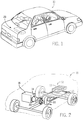
- FIG. 1 is a perspective view of an xEV 10 in the form of an automobile (e.g., a car) having a battery system (e.g., a Li-ion battery system 12) in accordance with present embodiments for providing a portion of the motive power for the vehicle 10, as described above.
- a battery system e.g., a Li-ion battery system 12
- the xEV 10 may be any of the types of xEVs described above, by specific example, the xEV 10 may be a mHEV, including an internal combustion engine equipped with a microhybrid system which includes a start-stop system that may utilize the Li-ion battery system 12 to power at least one or more accessories (e.g., AC, lights, consoles, etc.), as well as the ignition of the internal combustion engine, during start-stop cycles.
- accessories e.g., AC, lights, consoles, etc.
- the xEV 10 is illustrated as a car in FIG. 1 , the type of vehicle may differ in other embodiments, all of which are intended to fall within the scope of the present disclosure.
- the xEV 10 may be representative of a vehicle including a truck, bus, industrial vehicle, motorcycle, recreational vehicle, boat, or any other type of vehicle that may benefit from the use of electric power.
- the battery system 12 is illustrated in FIG. 1 as being positioned in the trunk or rear of the vehicle, according to other embodiments, the location of the battery system 12 may differ.
- the position of the battery system 12 may be selected based on the available space within a vehicle, the desired weight balance of the vehicle, the location of other components used with the battery system 12 (e.g., battery control units, measurement electronics, etc.), and a variety of other considerations.
- the xEV 10 may be an HEV having the battery system 12, which includes one or more battery modules 13, as illustrated in FIG. 2 .
- the battery system 12 illustrated in FIG. 2 is disposed toward the rear of the vehicle 10 proximate a fuel tank 14.
- the battery system 12 may be provided immediately adjacent the fuel tank 14, provided in a separate compartment in the rear of the vehicle 10 (e.g., a trunk), or provided in another suitable location in the HEV 10.
- the HEV 10 includes an internal combustion engine 16 for times when the HEV 10 utilizes gasoline power to propel the vehicle 10.
- the HEV 10 also includes an electric motor 18, a power split device 20, and a generator 22 as part of the drive system.
- the HEV 10 illustrated in FIG. 2 may be powered or driven by the battery system 12 alone, by the combustion engine 16 alone, or by both the battery system 12 and the combustion engine 16. It should be noted that, in other embodiments of the present approach, other types of vehicles and configurations for the vehicle drive system may be utilized, and that the schematic illustration of FIG. 2 should not be considered to limit the scope of the subject matter described in the present application. According to various embodiments, the size, shape, and location of the battery system 12 and the type of vehicle, among other features, may differ from those shown or described.
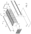
- the battery module 13 includes a plurality of Li-ion battery cells 24 that are contained within a battery module shell 26.
- the cells include at least one terminal, such as a positive terminal 28 and/or a negative terminal 30.
- the Li-ion battery cells 24 in the illustrated embodiment are provided side-by-side one another such that a face of the first Li-ion battery cell 24 is adjacent a face of the Li-ion second battery cell 24 (e.g., the cells face one another).
- the Li-ion cells 24 are stacked in an alternating fashion such that the positive terminal 28 of the first cell is provided adjacent the negative terminal 30 of the second cell.
- the negative terminal 30 of the first cell 24 is provided adjacent a positive terminal 28 of the second cell 24.
- Such an arrangement allows for efficient connection of the Li-ion battery cells 24 in series via bus bars.
- the Li-ion battery cells 24 may be otherwise arranged and/or connected (e.g., in parallel, or in a combination of series and parallel) in other embodiments.
- the battery module shell 26 for the battery module 13 includes a first side bracket 34 and a second side bracket 36.
- the shell 26 further includes a first end cap 38 and a second end cap 40.
- the end caps 38 and 40 are secured to the side brackets 34 and 36, respectively.
- the Li-ion battery cells 24 may be generally prismatic lithium-ion cells, as shown in the illustrated embodiment. According to other embodiments, the Li-ion battery cells 24 may have other physical configurations (e.g., oval, cylindrical, polygonal, etc.). Additionally, in some embodiments, the capacity, size, design, and other features of the Li-ion battery cells 24 may differ from those shown.
- Each Li-ion battery cell 24 includes a housing 44 (e.g., a can or container) through which the battery terminals 28 and 30 extend. Accordingly, it should be noted that each Li-ion battery cell 24 refers to a complete battery cell with a Li-ion battery cell element 45 contained within the housing 44. In certain embodiments of the present disclosure, each Li-ion battery cell element 45 may be contained within the battery module 13 without the housing 44. In such embodiments, elements of the battery module 13 (e.g., partitioning elements) may be utilized to electrically isolate portions of each Li-ion battery cell elements 45 from one another.
- elements of the battery module 13 e.g., partitioning elements
- Li-ion battery cell 24 referred to forthwith relates to a complete battery cell including the housing 44
- Li-ion battery cell element 45 or “cell element 45” refers to the jelly-roll shaped cell element 45 (e.g., wound or stacked electrodes) that may be placed within the housing 44 to form the complete Li-ion battery cell 24 (which may in turn be used in the battery module 13), or may be included directly in the battery module 13 without the housing 44.
- each Li-ion battery cell 24 includes a fill hole 46 through the housing 44 for introducing electrolyte into the battery cell 24, such that the battery cell element 45 of the battery cell 24 is immersed in electrolyte.
- the housing 44 may be a polymeric (e.g., plastic) housing 44 formed via an injection molding process.
- the housing 44 may be an electrically non-conductive polymeric housing 44.
- the battery module 13 may include fewer or more Li-ion battery cell elements 45 than shown in FIG. 3 . Additionally, in some embodiments, each battery cell element 45 may be placed directly into the battery module 13, without the housing 45 around each battery cell element 45. For example, in FIG. 4 , a partially exploded perspective view of an embodiment of the battery module 13 is shown with two Li-ion battery cell elements 45. However, the features of the battery module 13 shown in FIG. 4 may apply to a battery module 13 having more than two Li-ion battery cell elements 45.
- the battery module 13 includes a container 60 with two cell elements 45 separated by a partition 62.
- the battery module 13 also includes a lid 64 (or cover) with two terminals 66, 68. These terminals 66, 68 may be coupled to end terminals 28, 30 of the Li-ion battery cell elements 45 coupled together in series and/or in parallel within the container 60.
- the lid 64 also includes electrolyte fill holes 46, one over each Li-ion battery cell element 45, such that electrolyte may be introduced into the container 60 and each cell element 45 is immersed in electrolyte. Additionally, each cell element 45 in the illustrated embodiment is exposed within the container 60. In other words, the cell elements 45 do not include individual housings (e.g., housings 44 in FIG. 3 ).
- each cell element 45 forms a jelly roll shape (e.g., wound or stacked electrodes), and each cell element 45 fits into an individual compartment 72 in the battery module 13, where the compartments 72 are separated by the partition 62.
- the container 60 of the battery module 13 may include multiple partitions 62, such that the container 60 includes three or more compartments 72 for three or more cell elements 45.
- Each partition 62 electrically isolates the cell elements 45, except for an electrical connection between the cell elements 45 via electrical connectors 74.
- each cell element 45 may include electrical connectors 74 on either end. The electrical connectors 74 are configured to electrically couple the cell elements 45 in parallel or in series.
- the electrical connectors 74 may extend from the terminal 28 of one cell element 45 to the terminal 30 of another cell element 45 by extending over the partition 62 and under the lid 64, over the partition and through the lid 64 (e.g., partially embedded within the lid 64), or through an aperture in the partition 62. Additionally, each compartment 72 may contain electrolyte introduced into the container 60 through the electrolyte fill holes, as previously described. Once filled with electrolyte, sealed, and isolated, the two cell elements 45 form two Li-ion battery cells 24 in the module 13.
- the container 60 of the battery module 13 may not include the partition 62.
- each individual cell element 45 may include the housing 44 to form the Li-ion battery cell 24, as previously described with reference to FIG. 3 .
- the housing 44 is configured to electrically isolate the cell element 45 from other cell elements 45.
- the partition 62 may be included to electrically isolate cell elements 45.
- the container 60 may not include the partition 62, but each cell element 45 may include the housing 44 to electrically isolate each cell element 45 from one another.
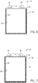
- FIG. 5 is a cross-sectional view an embodiment of the battery module 13 including the container 60 configured to retain Li-ion battery cells 24.
- the battery module 13 includes the container 60 and the cover 64, and the cover 64 includes the electrolyte fill holes 46 configured to align with electrolyte fill holes 46 of the cells 24.
- the electrolyte fill holes 46 may or may not be included in the container 60, as each Li-ion battery cell 24 may have electrolyte introduced into the cell 24 through fill holes 46 in the housing 44 before being placed in the container 60.
- the illustrated embodiment of the container 60 is configured to hold two Li-ion battery cells 24, other containers 60 in accordance with the present embodiment may include three or more Li-ion battery cells 24. It should be noted that features of the container 60 described below (with reference to FIGS. 5-7 ) may apply to the container 60 without the partition 62 (e.g., as shown in the illustrated embodiments) and to the container 60 with the partition 62.
- the container 60 with the cover 64 is formed by an electrically nonconductive polymeric (e.g., plastic) material.
- a moldable polymer e.g., plastic
- the container 60 may be injection molded into its final shape and may serve to electrically isolate the Li-ion battery cells 24 held therein.
- the polymer may be a moldable, heat sealable material that exhibits resistance to water migration, resistance to oxygen migration, resistance to hydrocarbon/organic carbonate migration, resistance to electrolyte migration, or two or more of these.
- polypropylene or polyphenylene sulfide (PPS) may be used as a water and/or chemical permeability barrier.
- polypropylene, PPS, and other polymers may not be sufficiently effective in preventing oxygen and certain fluid migration over the life time of the Li-ion battery cell 24 housed within the container 60, and thus may be reinforced with supplemental additives configured to prevent such migration.
- nanomaterials may be used to supplement polymer based containers 60 of the battery modules 13 in accordance with the present disclosure.
- materials such as silicate nanocomposites (e.g., exfoliated montmorillonite clay), nanocellulosic fibers, or individual or mixed nanometallic oxides may be blended with the polymer to form a composite 76, where the composite 76 is injection molded to form the container 60.
- the nanomaterial(s) may be coated onto the polymer and co-extruded in dual or multiple layers.
- the nanomaterial may be layered (e.g., by spraying the nanomaterial) over a polymer sheet or between two polymer sheets to form a multi-layer sheet, where the multi-layer sheet is injection molded and/or formed into the shape of the container 60.
- the nanomaterial e.g., nanosupplements
- the container 60 may be formed first, and the nanomaterial may be sprayed onto the container 60 after the container 60 is formed.
- the container 60 may be cheaper and more easily manufactured than it would be using traditional metal can configurations.
- the polymer material is cheaper than most metals, and enables the container 60 to be injection molded into its final shape for a more efficient production method.
- the container 60 may be injection molded around or integrally with other elements, such as a metal heat sink plate for thermal management, which will be described in detail with reference to later figures.
- the container 60 may exhibit enhanced impermeability properties relative to polypropylene, PPS, or other polymers alone.
- the composite 76 material may also be formed by a polymer base with additives used for enhanced thermal management.
- certain components of the Li-ion cells 24 operate best at temperatures between approximately 0 and 50° C.
- the Li-ion cells 24 may and their associated battery module 13 may reach temperatures of up to approximately 85° C.
- additives blended with the polymer base may enable increased thermal management of the Li-ion cells 24 and battery module 13.
- the additives may be materials that have higher thermal conductivities than the base polymer alone.
- the additive(s) may increase the overall thermal conductivity of the container 60.
- the composite container 60 may more easily transfer heat away from heat-sensitive components of the battery module 13 and toward a heat sink or other cooling system of the battery module 13.
- the composite 76 in the illustrated embodiment may include thermally conductive additives such as alumina (e.g., aluminum oxide), aluminum, brass, graphite, magnesium oxide, stainless steel, calcium carbonate, acetylene black, and/or glass.
- the additives may include flakes, fibers, powder, and/or microspheres added to the polymer (e.g., plastic) base.
- Thermal conductivity values for certain additives are in Table 1 shown below: Table 1 Composite Material Thermal Conductivity at Room Temperature Unfilled plastic polymers 0.17 - 0.35 W/mK Polyimide + 40% graphite 1.7 W/mK Rubber + Aluminum Oxide (Al 2 O 3 ) 0.6 W/mK Rubber + Aluminum flakes 1.0 W/mK
- certain commercially available products that include electrically non-conducting polymer plastics may also offer desirable thermal conductivity.
- certain COOLPOLY ® D-series dielectric plastics generally include additives to enhance thermal conductivity and may offer up to 10 W/mk thermal conductivity.
- certain COOLPOLY ® D-series dielectric plastics may be polymer blends or composites and may be used alone or may include additional additives described above.
- COOLPOLY ® D-series dielectric plastics (e.g., polymer blends or composites) may offer up to 10 W/mk or approximately 5-100 times the thermal conductivity of an unfilled plastic polymer.
- These dielectric plastics, other composite materials shown in Table 1, or other thermally conductive and electrically isolative polymers may be used to enhance the thermal conductivity of the housing 44 or the battery module 13 with the container 60.
- the container 60 may be formed using a moldable polymer material, as previously described, but in conjunction with a metallized coating on an inside of the battery module 13 for enhanced thermal management and/or permeability management.
- the metalized coating may include a pure metal, a metal alloy, a metal oxide, or a metal nitride.
- the metalized coating may be an aluminized layer.
- the aluminized layer may be pure aluminum, an aluminum alloy, aluminum oxide, or aluminum nitride.
- Other metals e.g. in the form of pure metals, metal alloys, metal oxides, or metal nitrides
- copper, steel, and nickel include copper, steel, and nickel.
- FIG. 6 is a cross-sectional view of an embodiment of the battery module 13 having the container 60, where the container 60 is made with a polymeric material, such as polypropylene, PPS, or some other plastic.
- the container 60 is coated on an inner wall 80 of the container 60 with an aluminized layer 82.
- the aluminized layer 82 may be added by sputtering a thin film onto the inner wall 80 of the container 60.
- the container 60 with the aluminized layer 82 may exhibit both enhanced thermal management properties and enhanced permeability properties.
- the aluminized layer 82 in the illustrated embodiment serves to extract heat from cell element 45 as well as block gasses and liquid from egress out of or ingress into the container 60.
- the aluminized layer 82 may extract heat from each cell element 45, and the heat may be spread evenly throughout the container 60 of the battery module 13. Thus, particular areas of the container 60 (e.g., particular cell elements 45 in the container 60) may not experience heat differentials relative to other areas of the container (e.g., other cell elements 45 in the container). Additionally, the aluminized layer 82 may block the electrolyte inside the container 60 from permeating the container 60.
- some other metal e.g., pure metal, metal alloy, metal oxide, or metal nitride
- metal capable of being added by sputtering a thin film or coating a thin film or layer on an inside of the container 60 may also be used for permeability and/or thermal management, as described above.
- FIG. 7 an embodiment of the battery module 13 in accordance with the present disclosure is shown in a cross-sectional illustration.
- the container 60 is formed with a composite 76 including a polymer base (e.g., polypropylene, PPS, or polyimide).
- the composite 76 may also include a nanomaterial to address permeability concerns (e.g., to combat ingress and egress of gases and/or liquids), as described with reference to FIG. 5 , an additive for generating a thermally enhanced polymer, as described with reference to FIG. 5 , or a combination of both.
- the container 60 may include an aluminum (or some other metal) layer 82 that may be coated on the inside surface 80 of the container 60, as described with reference to FIG. 6 .
- the composite 76 may make the container impermeable to undesired liquids and gases, while the aluminum layer 82 may enhance thermal management and/or provide additional permeability control.
- the composite 76 may enhance thermal management and the aluminum layer 82 may make the container impermeable to undesired liquids and gases.
- the resulting battery module 13 may include a moldable base polymer material that exhibits enhanced thermal management and enhanced permeability management at a reduced cost and with more flexible production methods (e.g., injection molding) than configurations that utilize an expensive metal material for the container 60.
- the container 60 of the battery module 13 may include cost-effective features that enable enhanced thermal management and permeability management of a polymer based battery system 12.
- the Li-ion battery cells 24 may include cost-effective features that enable enhanced thermal management and permeability management of the polymer (e.g., plastic) based battery system 12 as well.
- the polymer e.g., plastic
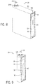
- FIG. 8 an embodiment of an individual, prismatic Li-ion battery cell 24 is shown in a cutaway perspective view in FIG. 8 .
- the individual Li-ion battery cell 24 includes a jelly roll shaped Li-ion electrochemical element 45 enclosed by a polymer (e.g., plastic) based housing 44.
- the polymer based housing 44 may be used instead of metal because it is cheaper and electrically insulates the Li-ion battery cell 24 from a surrounding environment 90.
- the polymer alone may not exhibit sufficient thermal management and/or permeability management properties. Accordingly, nanomaterials, additives, and other techniques and/or features described above may be applied to the housing 44 of the Li-ion battery cell 24.
- the polymer based housing 44 of the Li-ion battery cell 24 may be metalized on an external surface 92 of the housing 44, as shown in the illustrated embodiment.
- the polymer based housing 44 of the Li-ion battery cell 24 may be metalized on an internal surface 94 of the housing 44.
- the metallization enables a metalized layer 96 to control permeability of the individual Li-ion battery cell 24.
- the metalized layer 96 on the external surface 92 of the housing 44 may block ingress of moisture, gases, and/or other fluids or liquids through the polymer based housing 44 into the Li-ion battery cell 24.
- the metalized layer 96 on the internal surface 94 of the housing 44 may block egress of electrolyte through the polymer based housing 44 to the surrounding environment 90.
- the polymeric material of the housing 44 is protected from fluids saturating and/or negatively affecting the housing 44, and fluids are isolated from entering or exiting from inside the Li-ion battery cell 24.
- the housing may include the metalized layer 96 on the internal surface 94 of the housing 44 and the metalized layer 96 on the external surface 92 of the housing 44 to block both egress of electrolyte and ingress of moisture, gases, and/or other fluids.
- the Li-ion battery cell 24 may include one or more terminals 28 extending through an opening in the housing 44 and the metalized layer 96.
- a plastic seal ring 100 may be disposed around each terminal 28.
- the plastic seal ring 100 may extend from the housing 44 and through the metalized layer 96, such that the plastic seal ring 100 electrically isolates the terminal 28 from the metalized layer 96.
- the plastic seal ring 100 may also serve to seal the opening in the housing 44 through which the terminal 28 extends.
- the plastic seal ring 100 may be thermally shrink fit or crimped around the terminal 28, welded to the terminal 28 via laser or ultrasonic welding, or coupled to the terminal 28 in some other manner.
- the above described techniques may also apply to a Li-ion battery cell 24 that is not prismatic.
- a Li-ion battery cell 24 that is not prismatic.
- an embodiment of a cylindrical Li-ion battery cell 24 is shown in a cutaway perspective view in FIG. 9 .
- the metalized layer 96 is disposed on the external surface 92 of the housing 44, but may be disposed on the internal surface 94 of the housing 44 in other embodiments.
- the housing 44 may include a polymer (e.g., plastic) base with nanomaterial supplements and/or other thermally enhancing additives.
- the metallization surface 96 may serve as a permeability barrier and/or thermal management surface.
- the metalized layer 96 may be applied to both the external surface 92 and the internal surface 94 of the housing 44.
- welding techniques may be used to seal elements of the housing 44 of the Li-ion battery cell 24 or the container 60.
- an embodiment of the individual Li-ion battery cell 24 with the prismatic shape is shown in a cross-sectional view in FIG. 10 .
- the housing 44 of the Li-ion battery cell 24 may be enhanced by nanomaterials or other additives, as described above. Additionally, the housing 44 may have the metalized surface 96.
- the Li-ion battery cell 24 includes the cover 64 disposed in an opening of the housing 44 opposite a top 106 of the housing 44.
- the cover 64 may form a bottom 108 of the housing 44.
- an outer wall 109 e.g., a side wall
- the outer wall 109 may extend in an ovular or curved manner around the cell element 45, between the top 106 and the bottom 108 (e.g., the cover 64) of the housing 44.
- the cover 64 is made from a transmissive material (e.g., relative to heat and/or light) and the outer wall 109 of the housing 44 is made of an absorptive material (e.g., relative to heat and/or light).
- the transmissive material generally refers to a material configured to allow light and/or heat from a heat source to pass through it, while the absorptive material generally refers to a material configured to absorb heat from the heat source.
- the transmissive material may be substantially an unfilled grade of PPS, while the absorptive material may PPS based with glass and carbon additives.
- components formed by the absorptive material are configured to absorb heat and melt into the transmissive material.
- a laser welding tool 110 may transmit light and/or heat via a laser through the transmissive material of the cover 64 to the absorptive material of the outer wall 109.
- the outer wall 109 absorbs heat from the laser welding tool 100 and melts into the cover 64, thereby welding the cover 64 to the housing 44.
- the cover 64 may be made of the absorptive material and the outer wall 109 may be made of the transmissive material.
- the laser welding tool 110 may apply heat directly to the cover 64, such that the cover 64 absorbs heat from the laser welding tool 110 and melts into the outer wall 109.
- the cover 64 Upon melting into the outer wall 109, the cover 64 seals the bottom 108 of the housing to block ingress of moisture into the housing 44 and block egress of electrolyte out of the housing 44.
- the laser welding tool 110 may be positioned adjacent to the outer wall 109.
- an embodiment of the Li-ion battery cell 24 in accordance with the present disclosure is illustrated in a cross-sectional view in FIG. 11 .
- the outer wall 109 may be made from a transmissive material while the cover 64 is made from an absorptive material.
- the laser welding tool 110 is positioned such that the laser is directed through the outer wall 109.
- a lip 120 that extends around a perimeter of the cover 64 is configured to fit inside the outer wall 109 of the housing 44.
- the laser welding tool directs the heat from the laser through the transmissive material of the outer wall 109 to the lip 120 of the cover 64, melting the lip 120 into the outer wall 109.
- the outer wall 109 may be the absorptive material and the cover 64 may be the transmissive material. Accordingly, the outer wall 109 may absorb heat from the laser welding tool 110 and melt directly into the lip 120 of the cover 64.
- the transmissive and absorptive materials may include a polymer (e.g., plastic) base, as previously described. Additionally, the absorptive material may include glass and carbon additives. For example, the absorptive material may include approximately 20% glass and approximately 0.5% carbon additive.
- the transmissive material may be substantially an unfilled grade of PPS. Thus, it may be desirable to include a transmissive material for the cover 64, such that fillers and/or additives may be added to the housing 44 (which generally includes a greater volume than the cover 64) for enhanced thermal management and permeability management, as previously described. However, in another embodiment, both the housing 44 and the cover 64 may include additives for enhanced thermal management and permeability management.
- a portion of the cover 64 or housing 44 that serves as a welding surface may not include additives.
- the cover 64 may be graded such that the lip 120 does not include additives while all other portions of the cover 64 do include additives.
- the lip 120 may be an unfilled grade of PPS or some other polymer, such that the lip 120 includes the transmissive material, as described above.
- the housing 44 and the cover 64 together offer thermal and/or permeability management around the entirety of the cell 24.
- materials for material selection for the cover 64 and the housing 44 may be limited compared to materials for material selection for elements in other battery systems. Indeed, material selection for any of the above described features and/or techniques regarding the battery module 13 forming the container 60 and the individual Li-ion battery cells 24 is constrained by the electrolyte composition used in lithium ion applications. Accordingly, the material selection described above may enable the laser welding techniques described above, and the materials and techniques of the present disclosure may be tailored for use in Li-ion battery cell 24 and Li-ion battery system applications.
- Ultrasonic welding techniques may also be used for sealing the cover 64 to the outer wall 109 of the housing 44.
- the outer wall 109 includes a ridge 126 that contacts the cover 64.
- the ridge 126 may extend with the outer wall 109 around the Li-ion battery cell 24.
- the ridge 126 may be disposed over small ridges 128 of the cover 64.
- the small ridges 128 of the cover may extend between the lip 120 of the cover 64 and an outermost perimeter 130 of the cover 64.
- the small ridges 128 of the cover 64 may be disposed such that they are oriented substantially perpendicular to the ridge 126 of the outer wall 109.
- the small ridges 128 and the ridge 126 may be energy directors for an ultrasonic welding tool 132.
- the ultrasonic welding tool 132 may be a torsional ultrasonic welding tool 132.
- the ultrasonic welding tool 132 may be positioned adjacent to and/or in contact with the cover 64.
- the ultrasonic welding tool 132 may emit highfrequency ultrasonic acoustic vibrations that are locally applied while the cover 64 and the outer wall 109 of the housing 44 are pressed together. The vibrations may cause a solid-state weld to form between the outer wall 109 and the cover 64.
- the energy directors may focus energy at the edges of the small ridges 128 and the ridge 126 to urge the outer wall 109 and the cover 64 to join together, where the edges may form a 60-90° angle.
- the ridges may melt down such that the cover 64 and the outer wall 109 are joined and sealed without major crevices or irregular protrusions.
- the cover 64 might not include the small ridges 128, but rather a smooth surface.
- the materials of the outer wall 109 and the cover 64 may be the same as those used in the laser welding techniques described above, or the materials may be different.
- the materials may include additives and/or nanomaterials as previously described with reference to previous embodiments.
- the ridge 126 may be disposed on the cover 64 and the small ridges 128 may be disposed on the outer wall 109.
- the welding techniques discussed above may apply to welding of the cover 64 to the container 60 of the battery module 13.
- the welding techniques may apply to sealing the individual Li-ion electrochemical cells 24, the welding techniques may apply to sealing the container 60, or the welding techniques may apply to sealing the individual electrochemical cells 24 and the container 60.
- the welding techniques may generate a weld configured to block moisture from ingressing into the battery module 13 and/or configured to block electrolyte from egressing out of the battery module 13.
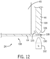
- FIG. 13 is a cross-sectional view of an embodiment of the battery module 13 having a U-shaped heat sink 140 molded into the container 60 of the battery module 13.
- the U-shaped heat sink 140 may have a U-shaped cross-sectional profile including a first leg 142, a second leg 144, and a connecting base member 146.
- the first leg 142 and the second leg 144 may extend into portions of the container 60 of the battery module 13 and the connecting base member 146 may be exposed to atmosphere (e.g., the environment 90).
- the container 60 includes a polymer (e.g., plastic) base material, as previously described, and may have any of the additives and/or nanosupplements described above.
- the container 60 may have the partition 62 configured to electrically isolate the cell elements 45.
- the cell elements 45 may, however, be electrically connected in series or parallel via the electrical connectors 74, as previously described.
- the container 60 in the illustrated embodiment may have the U-shaped heat sink 140 molded into the walls of the container 60, which may be enabled by the previously described material selection of the container 60.
- the molded in U-shaped heat sink 140 may be configured to extract heat from the cell elements 45 and/or the container 60 holding the cell elements 45 and the container 60.
- the U-shaped heat sink 140 in the illustrated embodiment spans two cell elements 45. In another embodiment, the U-shaped heat sink 140 may span one cell element 45, three cell elements 45, or more than three cell elements 45, depending on a desired thermal management of the battery module 13.
- U-shaped heat sinks 140 may be used in a single battery module 13, and the U-shaped heat sinks 140 may be integrally formed together such that one leg of a first U-shaped heat sink 140 makes up one leg of a second U-shaped heat sink 140.
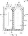
- FIG. 14 is a cross-sectional view of an embodiment of the battery module 13 having the container 60 with L-shaped heat sinks 150.
- each L-shaped heat sink 150 spans one cell element 45.
- each L-shaped heat sink 150 may span two or more cell elements 45.
- a vertical heat sink element 152 may be disposed at an end of the battery module 13 forming the container 60 such that each cell element 45 has an equal surface area adjacent to the heat sinks. In other words, the vertical heat sink element 152 ensures that the outermost cell element 45 has a heat sink element adjacent to its outermost surface.
- the battery module 13 may include L-shaped heat sinks 150 across each of the cell elements 45 except for the cell element 45 farthest to the right (e.g., from the perspective of the illustrated embodiment).
- the furthest cell element 45 to the right may include a U-shaped heat sink 140, as previously described, such that it has equal heat sink coverage as the other cell element(s) 45, without needing the vertical heat sink element 152 as previously described.
- the U-shaped heat sinks 140 and the L-shaped heat sinks 152 may be descriptive of the cross-sectional views in FIGS. 13 and 14 , but that the U-shaped heat sinks 140 and the L-shaped heat sinks 152 may actually extend around the container 60 of the battery module 13.
- the U-shaped heat sinks 140 together and the L-shaped heat sinks 152 together may extend into and out of the presently illustrated cross-sectional views to form an open prismatic container (e.g., open at a top of the heat sinks) that is molded into the container 60.
- an open prismatic container e.g., open at a top of the heat sinks
- a greater surface area of the Li-ion battery cells 24 is adjacent to the heat sinks 140, 150 for greater heat extraction.
- a bottom 154 of the U-shaped heat sink 140 (e.g., the connecting base member 146) and/or the L-shaped heat sink 150 in each respective embodiment may be exposed to the environment 90 such that an active cooling agent may pass over the bottom 154 for active cooling.
- an active cooling agent may pass over the bottom 154 for active cooling.
- a fan may blow air or a pump may pump cooling fluid over the bottom 154 for enhanced heat extraction.
- polymeric e.g., plastic
- production costs and part costs are reduced compared to configurations utilizing metal materials.
- Thermal management and permeability concerns may be addressed by including nanosupplements and additives, as well as metalized and/or aluminized surfaces, as described above.
- polymeric materials may be over molded or injection molded with a heat sink for additional thermal management.
Description
- The disclosure relates generally to the field of batteries and battery modules. More specifically, the present disclosure relates to polymerized (e.g., plastic) lithium ion battery modules.
- A vehicle that uses one or more battery systems for providing all or a portion of the motive power for the vehicle can be referred to as an xEV, where the term "xEV" is defined herein to include all of the following vehicles, or any variations or combinations thereof, that use electric power for all or a portion of their vehicular motive force. As will be appreciated by those skilled in the art, hybrid electric vehicles (HEVs) combine an internal combustion engine propulsion system and a battery-powered electric propulsion system, such as 48 volt or 130 volt systems. The term HEV may include any variation of a hybrid electric vehicle. For example, full hybrid systems (FHEVs) may provide motive and other electrical power to the vehicle using one or more electric motors, using only an internal combustion engine, or using both. In contrast, mild hybrid systems (MHEVs) disable the internal combustion engine when the vehicle is idling and utilize a battery system to continue powering the air conditioning unit, radio, or other electronics, as well as to restart the engine when propulsion is desired. The mild hybrid system may also apply some level of power assist, during acceleration for example, to supplement the internal combustion engine. Mild hybrids are typically 96V to 130V and recover braking energy through a belt or crank integrated starter generator. Further, a micro-hybrid electric vehicle (mHEV) also uses a "Stop-Start" system similar to the mild hybrids, but the micro-hybrid systems of a mHEV may or may not supply power assist to the internal combustion engine and typically operate at a voltage below 60V. For the purposes of the present discussion, it should be noted that mHEVs typically do not technically use electric power provided directly to the crankshaft or transmission for any portion of the motive force of the vehicle, but an mHEV may still be considered as an xEV since it does use electric power to supplement a vehicle's power needs when the vehicle is idling with internal combustion engine disabled and may recover braking energy through an integrated starter generator. In addition, a plug-in electric vehicle (PEV) is any vehicle that can be charged from an external source of electricity, such as wall sockets, and the energy stored in the rechargeable battery packs drives or contributes to drive the wheels. PEVs are a subcategory of electric vehicles that include all-electric or battery electric vehicles (BEVs), plug-in hybrid electric vehicles (PHEVs), and electric vehicle conversions of hybrid electric vehicles and conventional internal combustion engine vehicles.
- Vehicles using electric power for all or a portion of their motive power may provide numerous advantages as compared to traditional vehicles powered by internal combustion engines. For example, vehicles using electric power may produce fewer pollutants and may exhibit greater fuel efficiency. In some cases, vehicles using electric power may eliminate the use of gasoline entirely and derive the entirety of their motive force from electric power. As technology continues to evolve, there is a need to provide improved power sources, particularly battery modules, for such vehicles.
- Vehicles using electric power for at least a portion of their motive force may derive their electric power from multiple individual battery cells, which may be packaged into battery modules. In particular, multiple lithium ion battery cells or cell elements may be packaged into battery modules. Lithium ion battery cells or cell elements and their associated battery module(s) may operate at elevated temperatures (e.g., between 0 and 85° C) compared to traditional lead acid batteries, so they are typically packaged in a material that facilitates cooling. Also, lithium ion cell elements are particularly susceptible to oxygen or moisture, so they are typically packaged in a hermetically sealed metal housing. However, due to the limitations of metal fabrication, form factors are similarly limited. Accordingly, there is a need for addressing thermal management and permeability concerns described above in a cost effective manner that enables efficient production methods and techniques.
-
EP1278263 discloses a prismatic battery cell comprising a housing made of an electrically nonconductive polymeric material and an aluminum plate integrally embedded by insert molding in the sidewalls of the housing and exposed along the bottom portion of the housing. The battery cell is a nickel-metal hydride type battery. - The present disclosure is directed to a lithium ion (Li-ion) battery module including a container with one or more partitions extending from a bottom portion of the container to define compartments within the container. Each of the compartments is configured to receive and hold a prismatic Li-ion electrochemical element. The container includes an electrically nonconductive polymeric material. Additionally, a plurality of heat sinks disposed adjacent to one another and overmolded by the polymeric material of the container such that each heat sink is retained in one of the partitions of the container or in a side wall of the container and is exposed along the bottom portion of the container.
- Present embodiments of the disclosure are also directed to a method for manufacturing a lithium ion (Li-ion) battery module. The method includes overmolding a heat sink with an electrically nonconductive polymeric (e.g., plastic) material to form a container.
- These and other features, aspects, and advantages of the present disclosure will become better understood when the following detailed description is read with reference to the accompanying drawings in which like characters represent like parts throughout the drawings, wherein:
-
FIG. 1 is a perspective view of an embodiment of a vehicle having a battery module to provide power for various components of the vehicle, in accordance with the present techniques; -
FIG. 2 is a cutaway schematic view of an embodiment of the vehicle and the battery module ofFIG. 1 , in accordance with the present techniques; -
FIG. 3 is a partial exploded perspective view of an embodiment of the battery module for use in the vehicle ofFIG. 1 , in accordance with the present techniques; -
FIG. 4 is a partial exploded perspective view of another embodiment of the battery module for use in the vehicle ofFIG. 1 , in accordance with the present techniques; -
FIG. 5 is a cross-sectional view of an embodiment of a container for the battery module for use in the vehicle ofFIG. 1 , in accordance with the present techniques; -
FIG. 6 is a cross-sectional view of another embodiment of a container for the battery module for use in the vehicle ofFIG. 1 , in accordance with the present techniques; -
FIG. 7 is a cross-sectional view of another embodiment of a container for the battery module for use in the vehicle ofFIG. 1 , in accordance with the present techniques; -
FIG. 8 is a cutaway perspective view of an embodiment of a prismatic electrochemical cell, in accordance with the present techniques; -
FIG. 9 is a cutaway perspective view of an embodiment of a cylindrical electrochemical cell, in accordance with the present techniques; -
FIG. 10 is a cross-sectional view of an embodiment of a housing for use in the prismatic electrochemical cell ofFIG. 8 , in accordance with the present techniques; -
FIG. 11 is a cross-sectional view of another embodiment of a housing for use in the prismatic electrochemical cell ofFIG. 8 , in accordance with the present techniques; -
FIG. 12 is a partial cross-sectional view of a portion of an embodiment of a housing being welded for use in the prismatic electrochemical cell ofFIG. 8 , in accordance with the present techniques; -
FIG. 13 is a cross-sectional view of an embodiment of the battery module for use in the vehicle ofFIG. 1 , in accordance with the present techniques; and -
FIG. 14 is a cross-sectional view of another embodiment of the battery module for use in the vehicle ofFIG. 1 , in accordance with the present techniques. - The battery systems described herein may be used to provide power to various types of electric vehicles and other high voltage energy storage/expending applications (e.g., electrical grid power storage systems). Such battery systems may include one or more battery modules, each battery module having a number of battery cells (e.g., lithium ion (herein "Li-ion") electrochemical cells) containing cell elements arranged to provide particular voltages and/or currents useful to power, for example, one or more components of an xEV. In accordance with the present disclosure, polymeric (e.g., plastic) materials may be used for a portion of each battery module (e.g., a container formed by the battery module) and/or a portion of each Li-ion electrochemical cell (e.g., a housing of the Li-ion electrochemical cell surrounding the cell element). By using polymeric housings and/or containers, production cost is reduced compared to traditional Li-ion battery modules that include expensive and harder to form metal materials. Plastic housings and containers enable lower piece price, lower tooling costs, shorter lead times, reduced part quantities, and greater processing flexibility and efficiency. For example, a traditional metal housing for a cell element may include a non-conducting sleeve around the metal housing to prevent electrical shorts. Processing the traditional metal housing and sleeve separately may lengthen the manufacturing process and increase the number of parts for the battery module, both of which may increase production cost. Using polymeric materials for the housing may reduce production cost and time. Additionally, polymeric materials enable injection molding around non-polymeric materials, such as to address thermal control issues. Certain polymeric formulations and/or coatings may be used to address permeability issues and/or thermal conductivity.
- With the foregoing in mind, the Li-ion electrochemical cells (or cell elements) of each battery module may generate heat, which may cause the battery modules to operate at an elevated temperature. For example, battery modules of the present disclosure may operate at temperatures up to 85° Celsius. Traditional molded polymers may be poor thermal conductors. Additionally, traditional molded polymers may be susceptible to water, oxygen, hydrocarbon/organic carbonate, and/or electrolyte migration or permeability that may negatively affect the Li-ion electrochemical cells. Accordingly, there is a need for improved thermal management and permeability management of battery systems with polymer based housings and/or battery modules (e.g., containers), in order to produce the battery modules at reduced costs and with greater efficiency.
- Presently disclosed embodiments are directed to polymer (e.g., plastic) battery systems that include various features to promote thermal management and impermeability of the polymer battery components. In some embodiments, each Li-ion electrochemical cell may include features that address thermal management and permeability management concerns. In other embodiments, the battery module and its associated elements (e.g., the container formed by the battery module) may include features that address thermal management and permeability management concerns. In still other embodiments, each Li-ion electrochemical cell and the battery module may both include features that address thermal management and permeability management concerns. In accordance with the present disclosure, thermal management and/or permeability management concerns may be addressed at the cell and/or module level by using polymeric cell housings and/or module containers with nanomaterial additives, using thermally enhanced polymeric composite housings and/or containers, metalizing the outside and/or inside of housings and/or containers (e.g., metalizing with aluminum), and/or using polymeric housings and/or containers with molded-in heat sink plates. Nanomaterial additives, metalized surfaces, and molded in heat sinks enable sufficient thermal management and permeability management that may arise from concerns associated with using plastic materials. Additionally, in accordance with the present disclosure, laser welding and/or ultrasonic welding techniques may be adapted to enhance and enable impermeability of cells and battery modules that include a polymer (e.g., plastic) base material with additives, nanosupplements, and/or metalized layers.
- With the foregoing in mind,
FIG. 1 is a perspective view of anxEV 10 in the form of an automobile (e.g., a car) having a battery system (e.g., a Li-ion battery system 12) in accordance with present embodiments for providing a portion of the motive power for thevehicle 10, as described above. Although thexEV 10 may be any of the types of xEVs described above, by specific example, thexEV 10 may be a mHEV, including an internal combustion engine equipped with a microhybrid system which includes a start-stop system that may utilize the Li-ion battery system 12 to power at least one or more accessories (e.g., AC, lights, consoles, etc.), as well as the ignition of the internal combustion engine, during start-stop cycles. - Further, although the
xEV 10 is illustrated as a car inFIG. 1 , the type of vehicle may differ in other embodiments, all of which are intended to fall within the scope of the present disclosure. For example, thexEV 10 may be representative of a vehicle including a truck, bus, industrial vehicle, motorcycle, recreational vehicle, boat, or any other type of vehicle that may benefit from the use of electric power. Additionally, while thebattery system 12 is illustrated inFIG. 1 as being positioned in the trunk or rear of the vehicle, according to other embodiments, the location of thebattery system 12 may differ. For example, the position of thebattery system 12 may be selected based on the available space within a vehicle, the desired weight balance of the vehicle, the location of other components used with the battery system 12 (e.g., battery control units, measurement electronics, etc.), and a variety of other considerations. - In some embodiments, the
xEV 10 may be an HEV having thebattery system 12, which includes one ormore battery modules 13, as illustrated inFIG. 2 . In particular, thebattery system 12 illustrated inFIG. 2 is disposed toward the rear of thevehicle 10 proximate afuel tank 14. In other embodiments, thebattery system 12 may be provided immediately adjacent thefuel tank 14, provided in a separate compartment in the rear of the vehicle 10 (e.g., a trunk), or provided in another suitable location in theHEV 10. Further, as illustrated inFIG. 2 , theHEV 10 includes aninternal combustion engine 16 for times when theHEV 10 utilizes gasoline power to propel thevehicle 10. TheHEV 10 also includes anelectric motor 18, apower split device 20, and agenerator 22 as part of the drive system. - The
HEV 10 illustrated inFIG. 2 may be powered or driven by thebattery system 12 alone, by thecombustion engine 16 alone, or by both thebattery system 12 and thecombustion engine 16. It should be noted that, in other embodiments of the present approach, other types of vehicles and configurations for the vehicle drive system may be utilized, and that the schematic illustration ofFIG. 2 should not be considered to limit the scope of the subject matter described in the present application. According to various embodiments, the size, shape, and location of thebattery system 12 and the type of vehicle, among other features, may differ from those shown or described. - One embodiment of a
suitable battery module 13 is illustrated in an exploded perspective view inFIG. 3 . As shown, thebattery module 13 includes a plurality of Li-ion battery cells 24 that are contained within abattery module shell 26. According to an embodiment, the cells include at least one terminal, such as apositive terminal 28 and/or anegative terminal 30. - The Li-
ion battery cells 24 in the illustrated embodiment are provided side-by-side one another such that a face of the first Li-ion battery cell 24 is adjacent a face of the Li-ion second battery cell 24 (e.g., the cells face one another). According to the illustrated embodiment, the Li-ion cells 24 are stacked in an alternating fashion such that thepositive terminal 28 of the first cell is provided adjacent thenegative terminal 30 of the second cell. Likewise, thenegative terminal 30 of thefirst cell 24 is provided adjacent apositive terminal 28 of thesecond cell 24. Such an arrangement allows for efficient connection of the Li-ion battery cells 24 in series via bus bars. However, the Li-ion battery cells 24 may be otherwise arranged and/or connected (e.g., in parallel, or in a combination of series and parallel) in other embodiments. - In the illustrated embodiment, the
battery module shell 26 for thebattery module 13 includes afirst side bracket 34 and asecond side bracket 36. Theshell 26 further includes afirst end cap 38 and asecond end cap 40. As shown, the end caps 38 and 40 are secured to theside brackets ion battery cells 24 may be generally prismatic lithium-ion cells, as shown in the illustrated embodiment. According to other embodiments, the Li-ion battery cells 24 may have other physical configurations (e.g., oval, cylindrical, polygonal, etc.). Additionally, in some embodiments, the capacity, size, design, and other features of the Li-ion battery cells 24 may differ from those shown. - Each Li-
ion battery cell 24 includes a housing 44 (e.g., a can or container) through which thebattery terminals ion battery cell 24 refers to a complete battery cell with a Li-ionbattery cell element 45 contained within thehousing 44. In certain embodiments of the present disclosure, each Li-ionbattery cell element 45 may be contained within thebattery module 13 without thehousing 44. In such embodiments, elements of the battery module 13 (e.g., partitioning elements) may be utilized to electrically isolate portions of each Li-ionbattery cell elements 45 from one another. Thus, "Li-ion battery cell 24" referred to forthwith relates to a complete battery cell including thehousing 44, and "Li-ionbattery cell element 45" or "cell element 45" refers to the jelly-roll shaped cell element 45 (e.g., wound or stacked electrodes) that may be placed within thehousing 44 to form the complete Li-ion battery cell 24 (which may in turn be used in the battery module 13), or may be included directly in thebattery module 13 without thehousing 44. - In the illustrated embodiment, each Li-
ion battery cell 24 includes afill hole 46 through thehousing 44 for introducing electrolyte into thebattery cell 24, such that thebattery cell element 45 of thebattery cell 24 is immersed in electrolyte. In present embodiments, thehousing 44 may be a polymeric (e.g., plastic)housing 44 formed via an injection molding process. In particular, thehousing 44 may be an electrically non-conductivepolymeric housing 44. - In some embodiments, the
battery module 13 may include fewer or more Li-ionbattery cell elements 45 than shown inFIG. 3 . Additionally, in some embodiments, eachbattery cell element 45 may be placed directly into thebattery module 13, without thehousing 45 around eachbattery cell element 45. For example, inFIG. 4 , a partially exploded perspective view of an embodiment of thebattery module 13 is shown with two Li-ionbattery cell elements 45. However, the features of thebattery module 13 shown inFIG. 4 may apply to abattery module 13 having more than two Li-ionbattery cell elements 45. - In the illustrated embodiment, the
battery module 13 includes acontainer 60 with twocell elements 45 separated by apartition 62. Thebattery module 13 also includes a lid 64 (or cover) with twoterminals terminals terminals battery cell elements 45 coupled together in series and/or in parallel within thecontainer 60. Thelid 64 also includes electrolyte fill holes 46, one over each Li-ionbattery cell element 45, such that electrolyte may be introduced into thecontainer 60 and eachcell element 45 is immersed in electrolyte. Additionally, eachcell element 45 in the illustrated embodiment is exposed within thecontainer 60. In other words, thecell elements 45 do not include individual housings (e.g.,housings 44 inFIG. 3 ). In this example, eachcell element 45, as previously described, forms a jelly roll shape (e.g., wound or stacked electrodes), and eachcell element 45 fits into anindividual compartment 72 in thebattery module 13, where thecompartments 72 are separated by thepartition 62. In certain embodiments, thecontainer 60 of thebattery module 13 may includemultiple partitions 62, such that thecontainer 60 includes three ormore compartments 72 for three ormore cell elements 45. Eachpartition 62 electrically isolates thecell elements 45, except for an electrical connection between thecell elements 45 viaelectrical connectors 74. For example, eachcell element 45 may includeelectrical connectors 74 on either end. Theelectrical connectors 74 are configured to electrically couple thecell elements 45 in parallel or in series. Theelectrical connectors 74 may extend from theterminal 28 of onecell element 45 to theterminal 30 of anothercell element 45 by extending over thepartition 62 and under thelid 64, over the partition and through the lid 64 (e.g., partially embedded within the lid 64), or through an aperture in thepartition 62. Additionally, eachcompartment 72 may contain electrolyte introduced into thecontainer 60 through the electrolyte fill holes, as previously described. Once filled with electrolyte, sealed, and isolated, the twocell elements 45 form two Li-ion battery cells 24 in themodule 13. - In some embodiments, the
container 60 of thebattery module 13 may not include thepartition 62. In such embodiments, eachindividual cell element 45 may include thehousing 44 to form the Li-ion battery cell 24, as previously described with reference toFIG. 3 . Accordingly, thehousing 44 is configured to electrically isolate thecell element 45 fromother cell elements 45. In other words, in some embodiments, thepartition 62 may be included to electrically isolatecell elements 45. In other embodiments, thecontainer 60 may not include thepartition 62, but eachcell element 45 may include thehousing 44 to electrically isolate eachcell element 45 from one another. One such embodiment of thecontainer 60 without thepartition 62 is shown inFIG. 5 , which is a cross-sectional view an embodiment of thebattery module 13 including thecontainer 60 configured to retain Li-ion battery cells 24. In the illustrated embodiment, thebattery module 13 includes thecontainer 60 and thecover 64, and thecover 64 includes the electrolyte fill holes 46 configured to align with electrolyte fill holes 46 of thecells 24. The electrolyte fill holes 46 may or may not be included in thecontainer 60, as each Li-ion battery cell 24 may have electrolyte introduced into thecell 24 through fill holes 46 in thehousing 44 before being placed in thecontainer 60. Although the illustrated embodiment of thecontainer 60 is configured to hold two Li-ion battery cells 24,other containers 60 in accordance with the present embodiment may include three or more Li-ion battery cells 24. It should be noted that features of thecontainer 60 described below (with reference toFIGS. 5-7 ) may apply to thecontainer 60 without the partition 62 (e.g., as shown in the illustrated embodiments) and to thecontainer 60 with thepartition 62. - In the illustrated embodiment, the
container 60 with thecover 64 is formed by an electrically nonconductive polymeric (e.g., plastic) material. By using a moldable polymer (e.g., plastic) instead of a metal, thecontainer 60 may be injection molded into its final shape and may serve to electrically isolate the Li-ion battery cells 24 held therein. In some embodiments, the polymer may be a moldable, heat sealable material that exhibits resistance to water migration, resistance to oxygen migration, resistance to hydrocarbon/organic carbonate migration, resistance to electrolyte migration, or two or more of these. For example, polypropylene or polyphenylene sulfide (PPS) may be used as a water and/or chemical permeability barrier. However, polypropylene, PPS, and other polymers (e.g., polyimide, polyamide, polyethylene (PET), etc.) may not be sufficiently effective in preventing oxygen and certain fluid migration over the life time of the Li-ion battery cell 24 housed within thecontainer 60, and thus may be reinforced with supplemental additives configured to prevent such migration. - Accordingly, nanomaterials may be used to supplement polymer based
containers 60 of thebattery modules 13 in accordance with the present disclosure. For example, materials such as silicate nanocomposites (e.g., exfoliated montmorillonite clay), nanocellulosic fibers, or individual or mixed nanometallic oxides may be blended with the polymer to form a composite 76, where the composite 76 is injection molded to form thecontainer 60. In some embodiments, the nanomaterial(s) may be coated onto the polymer and co-extruded in dual or multiple layers. For example, the nanomaterial may be layered (e.g., by spraying the nanomaterial) over a polymer sheet or between two polymer sheets to form a multi-layer sheet, where the multi-layer sheet is injection molded and/or formed into the shape of thecontainer 60. In some embodiments, the nanomaterial (e.g., nanosupplements) may be applied as films or coatings over apre-formed polymer container 60. For example, thecontainer 60 may be formed first, and the nanomaterial may be sprayed onto thecontainer 60 after thecontainer 60 is formed. - In any of the above described embodiments utilizing a polymer base with nanomaterial additives, the
container 60 may be cheaper and more easily manufactured than it would be using traditional metal can configurations. For example, as described above, the polymer material is cheaper than most metals, and enables thecontainer 60 to be injection molded into its final shape for a more efficient production method. Additionally, thecontainer 60 may be injection molded around or integrally with other elements, such as a metal heat sink plate for thermal management, which will be described in detail with reference to later figures. Further, by utilizing nanomaterials in conjunction with the polymer base to form a nanocomposite, thecontainer 60 may exhibit enhanced impermeability properties relative to polypropylene, PPS, or other polymers alone. - The composite 76 material may also be formed by a polymer base with additives used for enhanced thermal management. In accordance with the present disclosure, certain components of the Li-
ion cells 24 operate best at temperatures between approximately 0 and 50° C. However, in some embodiments, the Li-ion cells 24 may and their associatedbattery module 13 may reach temperatures of up to approximately 85° C. Accordingly, additives blended with the polymer base may enable increased thermal management of the Li-ion cells 24 andbattery module 13. More specifically, the additives may be materials that have higher thermal conductivities than the base polymer alone. Thus, when added to the base polymer, the additive(s) may increase the overall thermal conductivity of thecontainer 60. As a result, thecomposite container 60 may more easily transfer heat away from heat-sensitive components of thebattery module 13 and toward a heat sink or other cooling system of thebattery module 13. - The composite 76 in the illustrated embodiment may include thermally conductive additives such as alumina (e.g., aluminum oxide), aluminum, brass, graphite, magnesium oxide, stainless steel, calcium carbonate, acetylene black, and/or glass. The additives may include flakes, fibers, powder, and/or microspheres added to the polymer (e.g., plastic) base. Thermal conductivity values for certain additives are in Table 1 shown below:
Table 1 Composite Material Thermal Conductivity at Room Temperature Unfilled plastic polymers 0.17 - 0.35 W/mK Polyimide + 40% graphite 1.7 W/mK Rubber + Aluminum Oxide (Al2O3) 0.6 W/mK Rubber + Aluminum flakes 1.0 W/mK - Additionally, certain commercially available products that include electrically non-conducting polymer plastics may also offer desirable thermal conductivity. For example, certain COOLPOLY® D-series dielectric plastics generally include additives to enhance thermal conductivity and may offer up to 10 W/mk thermal conductivity. In other words, certain COOLPOLY® D-series dielectric plastics may be polymer blends or composites and may be used alone or may include additional additives described above. Additionally, COOLPOLY® D-series dielectric plastics (e.g., polymer blends or composites) may offer up to 10 W/mk or approximately 5-100 times the thermal conductivity of an unfilled plastic polymer. These dielectric plastics, other composite materials shown in Table 1, or other thermally conductive and electrically isolative polymers may be used to enhance the thermal conductivity of the
housing 44 or thebattery module 13 with thecontainer 60. - In some embodiments, the
container 60 may be formed using a moldable polymer material, as previously described, but in conjunction with a metallized coating on an inside of thebattery module 13 for enhanced thermal management and/or permeability management. The metalized coating may include a pure metal, a metal alloy, a metal oxide, or a metal nitride. For example, the metalized coating may be an aluminized layer. In particular, the aluminized layer may be pure aluminum, an aluminum alloy, aluminum oxide, or aluminum nitride. Other metals (e.g. in the form of pure metals, metal alloys, metal oxides, or metal nitrides) that may be used include copper, steel, and nickel. - For example,
FIG. 6 is a cross-sectional view of an embodiment of thebattery module 13 having thecontainer 60, where thecontainer 60 is made with a polymeric material, such as polypropylene, PPS, or some other plastic. In the illustrated embodiment, thecontainer 60 is coated on aninner wall 80 of thecontainer 60 with an aluminizedlayer 82. The aluminizedlayer 82 may be added by sputtering a thin film onto theinner wall 80 of thecontainer 60. Thecontainer 60 with the aluminizedlayer 82 may exhibit both enhanced thermal management properties and enhanced permeability properties. In other words, the aluminizedlayer 82 in the illustrated embodiment serves to extract heat fromcell element 45 as well as block gasses and liquid from egress out of or ingress into thecontainer 60. The aluminizedlayer 82 may extract heat from eachcell element 45, and the heat may be spread evenly throughout thecontainer 60 of thebattery module 13. Thus, particular areas of the container 60 (e.g.,particular cell elements 45 in the container 60) may not experience heat differentials relative to other areas of the container (e.g.,other cell elements 45 in the container). Additionally, the aluminizedlayer 82 may block the electrolyte inside thecontainer 60 from permeating thecontainer 60. Additionally, it should be noted that some other metal (e.g., pure metal, metal alloy, metal oxide, or metal nitride) capable of being added by sputtering a thin film or coating a thin film or layer on an inside of thecontainer 60 may also be used for permeability and/or thermal management, as described above. - In some embodiments, techniques and features from the embodiments in
FIGS. 5 and6 may be used in combination. For example, inFIG. 7 , an embodiment of thebattery module 13 in accordance with the present disclosure is shown in a cross-sectional illustration. In the illustrated embodiment, thecontainer 60 is formed with a composite 76 including a polymer base (e.g., polypropylene, PPS, or polyimide). The composite 76 may also include a nanomaterial to address permeability concerns (e.g., to combat ingress and egress of gases and/or liquids), as described with reference toFIG. 5 , an additive for generating a thermally enhanced polymer, as described with reference toFIG. 5 , or a combination of both. Thecontainer 60 may include an aluminum (or some other metal)layer 82 that may be coated on theinside surface 80 of thecontainer 60, as described with reference toFIG. 6 . In some embodiments, the composite 76 may make the container impermeable to undesired liquids and gases, while thealuminum layer 82 may enhance thermal management and/or provide additional permeability control. In other embodiments, the composite 76 may enhance thermal management and thealuminum layer 82 may make the container impermeable to undesired liquids and gases. Accordingly, the resultingbattery module 13 may include a moldable base polymer material that exhibits enhanced thermal management and enhanced permeability management at a reduced cost and with more flexible production methods (e.g., injection molding) than configurations that utilize an expensive metal material for thecontainer 60. - In accordance with the present disclosure, similar techniques and materials as those described above (with reference to the battery modules 13) may be utilized to enhance thermal management and permeability management for each individual Li-
ion battery cell 24. As discussed above, thecontainer 60 of thebattery module 13 may include cost-effective features that enable enhanced thermal management and permeability management of a polymer basedbattery system 12. In addition to, or in lieu of these features, the Li-ion battery cells 24 may include cost-effective features that enable enhanced thermal management and permeability management of the polymer (e.g., plastic) basedbattery system 12 as well. For example, an embodiment of an individual, prismatic Li-ion battery cell 24 is shown in a cutaway perspective view inFIG. 8 . In the illustrated embodiment, the individual Li-ion battery cell 24 includes a jelly roll shaped Li-ionelectrochemical element 45 enclosed by a polymer (e.g., plastic) basedhousing 44. The polymer basedhousing 44 may be used instead of metal because it is cheaper and electrically insulates the Li-ion battery cell 24 from a surroundingenvironment 90. The polymer alone, however, may not exhibit sufficient thermal management and/or permeability management properties. Accordingly, nanomaterials, additives, and other techniques and/or features described above may be applied to thehousing 44 of the Li-ion battery cell 24. - Additionally, the polymer based
housing 44 of the Li-ion battery cell 24 (e.g., enclosing the cell element 45) may be metalized on anexternal surface 92 of thehousing 44, as shown in the illustrated embodiment. In another embodiment, the polymer basedhousing 44 of the Li-ion battery cell 24 may be metalized on aninternal surface 94 of thehousing 44. In either configuration, the metallization enables a metalizedlayer 96 to control permeability of the individual Li-ion battery cell 24. For example, the metalizedlayer 96 on theexternal surface 92 of thehousing 44 may block ingress of moisture, gases, and/or other fluids or liquids through the polymer basedhousing 44 into the Li-ion battery cell 24. The metalizedlayer 96 on theinternal surface 94 of thehousing 44 may block egress of electrolyte through the polymer basedhousing 44 to the surroundingenvironment 90. In both configurations, the polymeric material of thehousing 44 is protected from fluids saturating and/or negatively affecting thehousing 44, and fluids are isolated from entering or exiting from inside the Li-ion battery cell 24. Additionally, in some embodiments, the housing may include the metalizedlayer 96 on theinternal surface 94 of thehousing 44 and the metalizedlayer 96 on theexternal surface 92 of thehousing 44 to block both egress of electrolyte and ingress of moisture, gases, and/or other fluids. - The Li-
ion battery cell 24 may include one ormore terminals 28 extending through an opening in thehousing 44 and the metalizedlayer 96. Aplastic seal ring 100 may be disposed around each terminal 28. Theplastic seal ring 100 may extend from thehousing 44 and through the metalizedlayer 96, such that theplastic seal ring 100 electrically isolates the terminal 28 from the metalizedlayer 96. Theplastic seal ring 100 may also serve to seal the opening in thehousing 44 through which the terminal 28 extends. Theplastic seal ring 100 may be thermally shrink fit or crimped around the terminal 28, welded to the terminal 28 via laser or ultrasonic welding, or coupled to the terminal 28 in some other manner. - The above described techniques may also apply to a Li-
ion battery cell 24 that is not prismatic. For example, an embodiment of a cylindrical Li-ion battery cell 24 is shown in a cutaway perspective view inFIG. 9 . In the illustrated embodiment, the metalizedlayer 96 is disposed on theexternal surface 92 of thehousing 44, but may be disposed on theinternal surface 94 of thehousing 44 in other embodiments. As previously described, thehousing 44 may include a polymer (e.g., plastic) base with nanomaterial supplements and/or other thermally enhancing additives. Themetallization surface 96 may serve as a permeability barrier and/or thermal management surface. As previously described, the metalizedlayer 96 may be applied to both theexternal surface 92 and theinternal surface 94 of thehousing 44. - In order to enable a full permeability barrier for each individual Li-
ion battery cell 24 and/or thecontainer 60 of thebattery module 13 holding thecells 24, welding techniques may be used to seal elements of thehousing 44 of the Li-ion battery cell 24 or thecontainer 60. For example, an embodiment of the individual Li-ion battery cell 24 with the prismatic shape is shown in a cross-sectional view inFIG. 10 . In the illustrated embodiment, thehousing 44 of the Li-ion battery cell 24 may be enhanced by nanomaterials or other additives, as described above. Additionally, thehousing 44 may have the metalizedsurface 96. - The Li-
ion battery cell 24 includes thecover 64 disposed in an opening of thehousing 44 opposite a top 106 of thehousing 44. In other words, thecover 64 may form abottom 108 of thehousing 44. Additionally, an outer wall 109 (e.g., a side wall) may extend from the top 106 to thebottom 108 of thehousing 44, and theouter wall 109 may form a prismatic body of the Li-ion battery cell 24. Theouter wall 109 may extend in an ovular or curved manner around thecell element 45, between the top 106 and the bottom 108 (e.g., the cover 64) of thehousing 44. - In the illustrated embodiment, the
cover 64 is made from a transmissive material (e.g., relative to heat and/or light) and theouter wall 109 of thehousing 44 is made of an absorptive material (e.g., relative to heat and/or light). The transmissive material generally refers to a material configured to allow light and/or heat from a heat source to pass through it, while the absorptive material generally refers to a material configured to absorb heat from the heat source. For example, the transmissive material may be substantially an unfilled grade of PPS, while the absorptive material may PPS based with glass and carbon additives. - In the illustrated embodiment, components formed by the absorptive material are configured to absorb heat and melt into the transmissive material. For example, a
laser welding tool 110 may transmit light and/or heat via a laser through the transmissive material of thecover 64 to the absorptive material of theouter wall 109. Theouter wall 109 absorbs heat from thelaser welding tool 100 and melts into thecover 64, thereby welding thecover 64 to thehousing 44. It should be noted that, given the same position of thelaser welding tool 110 shown in the illustrated embodiment, thecover 64 may be made of the absorptive material and theouter wall 109 may be made of the transmissive material. In other words, thelaser welding tool 110 may apply heat directly to thecover 64, such that thecover 64 absorbs heat from thelaser welding tool 110 and melts into theouter wall 109. Upon melting into theouter wall 109, thecover 64 seals thebottom 108 of the housing to block ingress of moisture into thehousing 44 and block egress of electrolyte out of thehousing 44. - In another embodiment, the
laser welding tool 110 may be positioned adjacent to theouter wall 109. For example, an embodiment of the Li-ion battery cell 24 in accordance with the present disclosure is illustrated in a cross-sectional view inFIG. 11 . In this embodiment, theouter wall 109 may be made from a transmissive material while thecover 64 is made from an absorptive material. In the illustrated embodiment, thelaser welding tool 110 is positioned such that the laser is directed through theouter wall 109. Alip 120 that extends around a perimeter of thecover 64 is configured to fit inside theouter wall 109 of thehousing 44. Thus, in the illustrated embodiment, the laser welding tool directs the heat from the laser through the transmissive material of theouter wall 109 to thelip 120 of thecover 64, melting thelip 120 into theouter wall 109. As previously described, in another embodiment, theouter wall 109 may be the absorptive material and thecover 64 may be the transmissive material. Accordingly, theouter wall 109 may absorb heat from thelaser welding tool 110 and melt directly into thelip 120 of thecover 64. - In the embodiments discussed with reference to
FIGS. 10 and 11 , the transmissive and absorptive materials may include a polymer (e.g., plastic) base, as previously described. Additionally, the absorptive material may include glass and carbon additives. For example, the absorptive material may include approximately 20% glass and approximately 0.5% carbon additive. The transmissive material may be substantially an unfilled grade of PPS. Thus, it may be desirable to include a transmissive material for thecover 64, such that fillers and/or additives may be added to the housing 44 (which generally includes a greater volume than the cover 64) for enhanced thermal management and permeability management, as previously described. However, in another embodiment, both thehousing 44 and thecover 64 may include additives for enhanced thermal management and permeability management. In such embodiments, a portion of thecover 64 orhousing 44 that serves as a welding surface may not include additives. For example, thecover 64 may be graded such that thelip 120 does not include additives while all other portions of thecover 64 do include additives. As such, thelip 120 may be an unfilled grade of PPS or some other polymer, such that thelip 120 includes the transmissive material, as described above. Thus, thehousing 44 and thecover 64 together offer thermal and/or permeability management around the entirety of thecell 24. - It should be noted that, due to sensitivity of electrolyte used in the Li-
ion battery cells 24, materials for material selection for thecover 64 and thehousing 44 may be limited compared to materials for material selection for elements in other battery systems. Indeed, material selection for any of the above described features and/or techniques regarding thebattery module 13 forming thecontainer 60 and the individual Li-ion battery cells 24 is constrained by the electrolyte composition used in lithium ion applications. Accordingly, the material selection described above may enable the laser welding techniques described above, and the materials and techniques of the present disclosure may be tailored for use in Li-ion battery cell 24 and Li-ion battery system applications. - Ultrasonic welding techniques may also be used for sealing the
cover 64 to theouter wall 109 of thehousing 44. For example, a portion of an embodiment of the Li-ion battery cell 24 (e.g., the housing 44) being sealed via ultrasonic welding is shown inFIG. 12 . In the illustrated embodiment, theouter wall 109 includes aridge 126 that contacts thecover 64. Theridge 126 may extend with theouter wall 109 around the Li-ion battery cell 24. Theridge 126 may be disposed oversmall ridges 128 of thecover 64. Thesmall ridges 128 of the cover may extend between thelip 120 of thecover 64 and anoutermost perimeter 130 of thecover 64. Thesmall ridges 128 of thecover 64 may be disposed such that they are oriented substantially perpendicular to theridge 126 of theouter wall 109. - In the illustrated embodiment, the
small ridges 128 and theridge 126 may be energy directors for anultrasonic welding tool 132. In some embodiments, theultrasonic welding tool 132 may be a torsionalultrasonic welding tool 132. In the present embodiment, theultrasonic welding tool 132 may be positioned adjacent to and/or in contact with thecover 64. Theultrasonic welding tool 132 may emit highfrequency ultrasonic acoustic vibrations that are locally applied while thecover 64 and theouter wall 109 of thehousing 44 are pressed together. The vibrations may cause a solid-state weld to form between theouter wall 109 and thecover 64. The energy directors (e.g., thesmall ridges 128 of thecover 64 and theridge 126 of the outer wall 109) may focus energy at the edges of thesmall ridges 128 and theridge 126 to urge theouter wall 109 and thecover 64 to join together, where the edges may form a 60-90° angle. The ridges may melt down such that thecover 64 and theouter wall 109 are joined and sealed without major crevices or irregular protrusions. It should be noted that, in some embodiments, thecover 64 might not include thesmall ridges 128, but rather a smooth surface. The materials of theouter wall 109 and thecover 64 may be the same as those used in the laser welding techniques described above, or the materials may be different. For example, the materials may include additives and/or nanomaterials as previously described with reference to previous embodiments. Additionally, in some embodiments, theridge 126 may be disposed on thecover 64 and thesmall ridges 128 may be disposed on theouter wall 109. - It should be noted that the welding techniques discussed above (e.g., laser welding and ultrasonic welding) may apply to welding of the
cover 64 to thecontainer 60 of thebattery module 13. In other words, the welding techniques may apply to sealing the individual Li-ionelectrochemical cells 24, the welding techniques may apply to sealing thecontainer 60, or the welding techniques may apply to sealing the individualelectrochemical cells 24 and thecontainer 60. The welding techniques may generate a weld configured to block moisture from ingressing into thebattery module 13 and/or configured to block electrolyte from egressing out of thebattery module 13. - In accordance with the present disclosure, the above referenced techniques, features, and/or materials may be utilized for the Li-
ion battery cell 24, thebattery module 13 with thecontainer 60, or both. In additional to the above referenced techniques and materials, heat sinks are included in thecontainer 60 of thebattery module 13. For example,FIG. 13 is a cross-sectional view of an embodiment of thebattery module 13 having aU-shaped heat sink 140 molded into thecontainer 60 of thebattery module 13. TheU-shaped heat sink 140 may have a U-shaped cross-sectional profile including afirst leg 142, a second leg 144, and a connectingbase member 146. Thefirst leg 142 and the second leg 144 may extend into portions of thecontainer 60 of thebattery module 13 and the connectingbase member 146 may be exposed to atmosphere (e.g., the environment 90). Thecontainer 60 includes a polymer (e.g., plastic) base material, as previously described, and may have any of the additives and/or nanosupplements described above. Thecontainer 60 may have thepartition 62 configured to electrically isolate thecell elements 45. Thecell elements 45 may, however, be electrically connected in series or parallel via theelectrical connectors 74, as previously described. - The
container 60 in the illustrated embodiment may have theU-shaped heat sink 140 molded into the walls of thecontainer 60, which may be enabled by the previously described material selection of thecontainer 60. The molded inU-shaped heat sink 140 may be configured to extract heat from thecell elements 45 and/or thecontainer 60 holding thecell elements 45 and thecontainer 60. TheU-shaped heat sink 140 in the illustrated embodiment spans twocell elements 45. In another embodiment, theU-shaped heat sink 140 may span onecell element 45, threecell elements 45, or more than threecell elements 45, depending on a desired thermal management of thebattery module 13. Further, multipleU-shaped heat sinks 140 may be used in asingle battery module 13, and theU-shaped heat sinks 140 may be integrally formed together such that one leg of a firstU-shaped heat sink 140 makes up one leg of a secondU-shaped heat sink 140. - Additionally, the heat sink may not be U-shaped. For example,
FIG. 14 is a cross-sectional view of an embodiment of thebattery module 13 having thecontainer 60 with L-shaped heat sinks 150. In the illustrated embodiment, each L-shapedheat sink 150 spans onecell element 45. In another embodiment, each L-shapedheat sink 150 may span two ormore cell elements 45. Additionally, a verticalheat sink element 152 may be disposed at an end of thebattery module 13 forming thecontainer 60 such that eachcell element 45 has an equal surface area adjacent to the heat sinks. In other words, the verticalheat sink element 152 ensures that theoutermost cell element 45 has a heat sink element adjacent to its outermost surface. However, in another embodiment, thebattery module 13 may include L-shapedheat sinks 150 across each of thecell elements 45 except for thecell element 45 farthest to the right (e.g., from the perspective of the illustrated embodiment). Thefurthest cell element 45 to the right may include aU-shaped heat sink 140, as previously described, such that it has equal heat sink coverage as the other cell element(s) 45, without needing the verticalheat sink element 152 as previously described. - It should be noted that the
U-shaped heat sinks 140 and the L-shapedheat sinks 152 may be descriptive of the cross-sectional views inFIGS. 13 and14 , but that theU-shaped heat sinks 140 and the L-shapedheat sinks 152 may actually extend around thecontainer 60 of thebattery module 13. In other words, theU-shaped heat sinks 140 together and the L-shapedheat sinks 152 together may extend into and out of the presently illustrated cross-sectional views to form an open prismatic container (e.g., open at a top of the heat sinks) that is molded into thecontainer 60. Thus, a greater surface area of the Li-ion battery cells 24 is adjacent to theheat sinks bottom 154 of the U-shaped heat sink 140 (e.g., the connecting base member 146) and/or the L-shapedheat sink 150 in each respective embodiment may be exposed to theenvironment 90 such that an active cooling agent may pass over the bottom 154 for active cooling. For example, a fan may blow air or a pump may pump cooling fluid over the bottom 154 for enhanced heat extraction. - By using polymeric (e.g., plastic) materials for the Li-
ion battery cells 24 andbattery module 13 forming thecontainer 60, production costs and part costs are reduced compared to configurations utilizing metal materials. Thermal management and permeability concerns may be addressed by including nanosupplements and additives, as well as metalized and/or aluminized surfaces, as described above. Additionally, polymeric materials may be over molded or injection molded with a heat sink for additional thermal management. - While only certain features and embodiments of the invention have been illustrated and described, many modifications and changes may occur to those skilled in the art (e.g., variations in sizes, dimensions, structures, shapes and proportions of the various elements, values of parameters (e.g., temperatures, pressures, etc.), mounting arrangements, use of materials, colors, orientations, etc.) without materially departing from the novel teachings and advantages of the subject matter recited in the claims. The order or sequence of any process or method steps may be varied or re-sequenced according to alternative embodiments. It is, therefore, to be understood that the appended claims are intended to cover all such modifications and changes as fall within the scope of the invention. Furthermore, in an effort to provide a concise description of the exemplary embodiments, all features of an actual implementation may not have been described (i.e., those unrelated to the presently contemplated best mode of carrying out the invention, or those unrelated to enabling the claimed invention). It should be appreciated that in the development of any such actual implementation, as in any engineering or design project, numerous implementation specific decisions may be made. Such a development effort might be complex and time consuming, but would nevertheless be a routine undertaking of design, fabrication, and manufacture for those of ordinary skill having the benefit of this disclosure, without undue experimentation.
Claims (12)
- A lithium ion (Li-ion) battery module (13), comprising:- a container (60) comprising:- one or more partitions (62) extending from a bottom portion of the container (60) that define a plurality of compartments (72) within the container (60), wherein each of the plurality of compartments (72) is configured to receive and hold a prismatic Li-ion electrochemical cell element, wherein the container (60) comprises an electrically nonconductive polymeric material; and- a plurality of heat sinks (140, 150) disposed adjacent to one another and overmolded by the polymeric material of the container (60) such that each heat sink is retained in one of the partitions (62) of the container (60) or in a side wall of the container (60) and is exposed along the bottom portion of the container (60).
- The Li-ion battery module (13) of claim 1,
wherein each of the plurality of heat sinks (150) comprises an L-shaped cross-sectional profile, wherein the L-shaped cross-sectional profile comprises:- a first leg extending into and retained by the one of the partitions (62) of the container (60) or the side wall of the container (60);- a second leg (154) extending substantially perpendicular from the first leg, wherein the second leg (154) is exposed along the bottom portion of the container (60). - The Li-ion battery module (13) of claim 1,
wherein each of the plurality of heat sinks (140) comprises a U-shaped cross-sectional profile, wherein the U-shaped cross-sectional profile comprises:- a first leg (142) extending into and retained by a first one of the partitions (62) of the container (60) or the side wall of the container (60);- a second leg extending (144) into and retained by a second one of the partitions (62) of the container (60) or the side wall of the container (60); and- a connecting base member (146), wherein the connecting base member (146) is exposed along the bottom portion of the container (60). - The Li-ion battery module (13) of any one of claims 1 to 3,
wherein each of the plurality of heat sinks (140, 150) is disposed around a single compartment (72) of the plurality of compartments (72). - The Li-ion battery module (13) of any one of claims 1 to 4,
wherein each of the plurality of heat sinks (140, 150) comprises multiple legs extending into and retained by the partitions (62) of the container (60) such that the plurality of heat sinks (140, 150) are disposed around each of the plurality of compartments (72). - The Li-ion battery module (13) of one of claims 1 to 5,
wherein the polymeric material of the container (60) comprises a polymer blend having a nanomaterial mixed into a base polymer, wherein the nanomaterial is configured to enhance impermeability of the container (60) to reduce ingress of moisture into the container (60), to reduce egress of electrolyte from the container (60), or both. - The Li-ion battery module (13) of one of claims 1 to 6, comprising a metalized inner surface (80) of each compartment (72), wherein the metalized inner surface (80) is configured to enhance impermeability of the container (60) to reduce ingress of moisture into the container (60), to reduce egress of electrolyte from the container (60), or both.
- The Li-ion battery module (13) of one of claims 1 to 7, comprising a fan or pump configured to enable active heat transfer from the exposed portion of the heat sink (140, 150) by moving cooled air or fluid adjacent the exposed portion.
- The Li-ion battery module (13) of one of claims 1 to 8,
wherein the heat sink (140, 150) is exposed to an atmosphere along the bottom portion of the container (60). - A method for manufacturing a lithium ion (Li-ion) battery module (13), comprising:- overmolding a plurality of heat sinks (140, 150) disposed adjacent to one another with an electrically nonconductive polymeric material to form a container (60), wherein the container (60) comprises one or more partitions (62) extending from a bottom portion of the container (60) that define a plurality of compartments (72) within the container (60) to receive and hold prismatic Li-ion electrochemical cell elements (45);wherein the plurality of heat sinks (140, 150) is overmolded such that each heat sink (140, 150) is retained in a one of the partitions (62) of the container (60) or in a side wall of the container (60) and is exposed along the bottom portion of the container (60).
- The method of claim 10,
wherein the polymeric material comprises a polymer blend having a nanomaterial mixed with a base polymer, wherein the nanomaterial is configured to enhance impermeability of the container (60) to reduce ingress of moisture into the container (60), to reduce egress of electrolyte from the container (60), or both. - The method of claim 10 or 11, comprising:- coating the polymeric material with metal; and- overmolding the heat sink (140, 150) with the coated polymeric material.
Applications Claiming Priority (2)
| Application Number | Priority Date | Filing Date | Title |
|---|---|---|---|
| US201261746836P | 2012-12-28 | 2012-12-28 | |
| PCT/US2013/078053 WO2014106084A1 (en) | 2012-12-28 | 2013-12-27 | Polymerized lithium ion battery cells and modules with overmolded heat sinks |
Publications (2)
| Publication Number | Publication Date |
|---|---|
| EP2939293A1 EP2939293A1 (en) | 2015-11-04 |
| EP2939293B1 true EP2939293B1 (en) | 2017-11-29 |
Family
ID=51017533
Family Applications (2)
| Application Number | Title | Priority Date | Filing Date |
|---|---|---|---|
| EP13818968.3A Active EP2939292B1 (en) | 2012-12-28 | 2013-12-27 | Welding techniques for polymerized lithium ion battery cells and modules |
| EP13821414.3A Active EP2939293B1 (en) | 2012-12-28 | 2013-12-27 | Lithium ion battery modules with overmolded heat sinks |
Family Applications Before (1)
| Application Number | Title | Priority Date | Filing Date |
|---|---|---|---|
| EP13818968.3A Active EP2939292B1 (en) | 2012-12-28 | 2013-12-27 | Welding techniques for polymerized lithium ion battery cells and modules |
Country Status (4)
| Country | Link |
|---|---|
| US (4) | US9450275B2 (en) |
| EP (2) | EP2939292B1 (en) |
| CN (2) | CN105009321B (en) |
| WO (4) | WO2014106094A1 (en) |
Families Citing this family (51)
| Publication number | Priority date | Publication date | Assignee | Title |
|---|---|---|---|---|
| EP3499609B1 (en) | 2009-05-20 | 2023-11-22 | Clarios Advanced Solutions LLC | Lithium ion battery module |
| US20160056418A1 (en) * | 2014-08-21 | 2016-02-25 | Ford Global Technologies, Llc | Li-ion monoblock battery for stop/start applications |
| US10340483B2 (en) | 2014-08-26 | 2019-07-02 | Cps Technology Holdings Llc | Welding process for sealing a battery module |
| US10388920B2 (en) | 2014-08-26 | 2019-08-20 | Cps Technology Holdings Llc | Collar for sealing a battery module |
| US10020534B2 (en) | 2014-09-26 | 2018-07-10 | Johnson Controls Technology Company | Free floating battery cell assembly techniques for lithium ion battery module |
| US9825343B2 (en) * | 2014-09-30 | 2017-11-21 | Johnson Controls Technology Company | Battery module passive thermal management features and positioning |
| KR101804048B1 (en) * | 2015-04-22 | 2017-12-01 | 주식회사 엘지화학 | Secondary battery pack and vehicle comprising the same |
| US11302973B2 (en) | 2015-05-19 | 2022-04-12 | Ford Global Technologies, Llc | Battery assembly with multi-function structural assembly |
| KR102383192B1 (en) * | 2015-08-07 | 2022-04-06 | 삼성에스디아이 주식회사 | Battery pack |
| US10622687B2 (en) | 2015-08-10 | 2020-04-14 | Ford Global Technologies, Llc | Battery pack enclosure including integrated fluid channel |
| US11296370B2 (en) * | 2015-12-03 | 2022-04-05 | Eaglepicher Technologies, Llc | Battery having high thermal conductivity case |
| KR102223514B1 (en) | 2015-12-29 | 2021-03-05 | 에스케이이노베이션 주식회사 | Battery module |
| DE102017203250B4 (en) | 2016-03-01 | 2022-02-24 | GM Global Technology Operations LLC | ELECTRIC BICYCLE WITH A BATTERY PACK WITH INTEGRATED PASSIVE COOLING SYSTEM |
| US10411311B2 (en) * | 2016-03-01 | 2019-09-10 | GM Global Technology Operations LLC | Integrated passive cooling system and method |
| DE102016103841A1 (en) * | 2016-03-03 | 2017-09-07 | Johnson Controls Advanced Power Solutions Gmbh | Attachment of electrochemical cells in a housing of a battery module |
| CN105720219B (en) * | 2016-03-31 | 2018-09-18 | 苏州工业园区职业技术学院 | A kind of power battery pack convenient for safeguarding |
| CN105742756A (en) * | 2016-04-25 | 2016-07-06 | 珠海光环新能源科技有限公司 | Battery pack with radiating units |
| US11018392B2 (en) | 2016-07-07 | 2021-05-25 | Samsung Sdi Co., Ltd | Battery module carrier, battery module and vehicle with a battery system |
| US11139521B2 (en) | 2016-07-07 | 2021-10-05 | Samsung Sdi Co., Ltd. | Battery submodule carrier, battery submodule, battery system and vehicle |
| US10062876B2 (en) * | 2016-07-07 | 2018-08-28 | Samsung Sdi Co., Ltd. | Battery module carrier, battery module, and vehicle with a battery system |
| US11075423B2 (en) | 2016-07-07 | 2021-07-27 | Samsung Sdi Co., Ltd. | Battery submodule carrier, battery submodule, battery system and vehicle |
| US10873111B2 (en) * | 2016-08-09 | 2020-12-22 | Wisk Aero Llc | Battery with compression and prevention of thermal runaway propagation features |
| KR101912015B1 (en) | 2016-11-15 | 2018-10-25 | 엘지전자 주식회사 | Battery Pack |
| JP7152405B2 (en) * | 2017-01-24 | 2022-10-12 | ティコナ・エルエルシー | Battery modules for electric transportation equipment |
| KR102113299B1 (en) * | 2017-03-13 | 2020-05-20 | 주식회사 엘지화학 | A case for a secondary battery with enhanced safety and a secondary battery comprising the same |
| US10283824B2 (en) | 2017-04-21 | 2019-05-07 | Ford Global Technologies, Llc | Thermal exchange assembly for vehicle battery |
| JP6738541B2 (en) * | 2017-05-02 | 2020-08-12 | トヨタ自動車株式会社 | How to smoke an assembled battery |
| CN106972128B (en) * | 2017-06-01 | 2022-12-06 | 湖南宏迅亿安新能源科技有限公司 | Battery module |
| WO2019071176A1 (en) * | 2017-10-06 | 2019-04-11 | Johnson Controls Technology Company | Method for bonding thermoplastic components in a battery module |
| CN111629887A (en) * | 2017-10-31 | 2020-09-04 | 格雷腾能源有限公司 | Bipolar battery plate assembly and related mechanical coupling process |
| KR102643505B1 (en) | 2017-12-12 | 2024-03-04 | 삼성전자주식회사 | Battery case, battery, and method for fabricating a battery |
| JP7281676B2 (en) * | 2018-02-27 | 2023-05-26 | パナソニックIpマネジメント株式会社 | Battery module and battery pack |
| KR102591366B1 (en) | 2018-03-09 | 2023-10-18 | 삼성전자주식회사 | Battery case, battery, and method for fabricating a battery |
| US10601006B2 (en) | 2018-04-05 | 2020-03-24 | Ford Global Technologies, Llc | Method and battery assembly for electrified vehicle |
| US10756398B2 (en) | 2018-06-22 | 2020-08-25 | Wisk Aero Llc | Capacitance reducing battery submodule with thermal runaway propagation prevention and containment features |
| US10593920B2 (en) | 2018-08-13 | 2020-03-17 | Wisk Aero Llc | Capacitance reduction in battery systems |
| KR102373774B1 (en) * | 2018-08-21 | 2022-03-14 | 에스케이온 주식회사 | Battery Module and Battery Pack including the same |
| WO2020079705A1 (en) | 2018-10-16 | 2020-04-23 | Chairman, Defence Research & Development Organisation (DRDO) | A secondary prismatic alkaline battery twin cell |
| US10910683B2 (en) | 2018-11-19 | 2021-02-02 | Ford Global Technologies, Llc | Heat exchanger plate assembles for electrified vehicle battery packs |
| KR20200060585A (en) | 2018-11-21 | 2020-06-01 | 삼성전자주식회사 | Liquid crystal polymer, composite composition, article, battery case, and battery |
| US10985352B2 (en) * | 2018-12-06 | 2021-04-20 | Zoox, Inc. | Electrical system with thermal protection |
| CN111384464A (en) * | 2018-12-29 | 2020-07-07 | 宁德时代新能源科技股份有限公司 | Battery module and battery pack |
| WO2020163665A1 (en) * | 2019-02-08 | 2020-08-13 | Cps Technology Holdings L.L.C | Battery system having a passive heat sink |
| US20220190417A1 (en) * | 2019-04-18 | 2022-06-16 | Cps Technology Holdings Llc | Heat sink fixation through plastic melting |
| FR3095301B1 (en) * | 2019-04-19 | 2021-04-16 | Psa Automobiles Sa | PRISMATIC ELECTROCHEMICAL CELL STORAGE DEVICE WITH DRAINAGE INSERTS, AND ASSOCIATED BATTERY |
| CN209747613U (en) * | 2019-06-28 | 2019-12-06 | 江苏时代新能源科技有限公司 | battery module |
| US11121420B2 (en) | 2019-06-28 | 2021-09-14 | Jiangsu Contemporary Amperex Technology Limited | Battery module |
| AT522361B1 (en) * | 2019-09-05 | 2020-10-15 | Kreisel Electric Gmbh & Co Kg | Device for temperature control of battery cells |
| CN112046048A (en) * | 2020-08-20 | 2020-12-08 | 深圳市亿铭粤科技有限公司 | Manufacturing process of shell with heat dissipation function |
| CN113481759A (en) * | 2021-05-17 | 2021-10-08 | 南京金陵金箔集团股份有限公司 | Production process of lining paper for packaging |
| US20230253610A1 (en) * | 2022-02-09 | 2023-08-10 | Cuberg, Inc. | Battery assemblies comprising lithium-metal electrochemical cells and lithium-ejecta containment components |
Family Cites Families (55)
| Publication number | Priority date | Publication date | Assignee | Title |
|---|---|---|---|---|
| FR1069890A (en) * | 1953-01-21 | 1954-07-13 | Improvements to processes for shutting off lead-sulfuric acid batteries or accumulators | |
| FR1569708A (en) | 1968-02-29 | 1969-06-06 | ||
| US3620873A (en) * | 1969-03-26 | 1971-11-16 | Ercon Inc | Making metal-plastic gasket materials |
| DE2338908C3 (en) * | 1973-08-01 | 1981-06-04 | Elbatainer Kunststoff- Und Verpackungsgesellschaft Mbh, 7505 Ettlingen | Ultrasonic welding method and device for the liquid-tight welding of a closable pouring nozzle into a thin-walled liquid container and a pouring nozzle therefor |
| US3995008A (en) | 1975-02-20 | 1976-11-30 | Gould Inc. | Molded plastic battery container |
| US4029855A (en) | 1975-12-10 | 1977-06-14 | Globe-Union Inc. | Storage battery and method of making the same |
| US4150201A (en) | 1976-06-30 | 1979-04-17 | Aislantes Leon, S.A. | Multi-partitioned containers having metal connectors through the partitions and a mold assembly for producing same |
| US4107402A (en) | 1977-09-22 | 1978-08-15 | Globe-Union Inc. | Battery and battery container having air-flow passages therethrough |
| US4121017A (en) | 1977-10-25 | 1978-10-17 | Globe-Union Inc. | Portable rechargeable lead-acid battery |
| US4485959A (en) | 1982-05-14 | 1984-12-04 | Gnb Batteries Inc. | Means for welding intercell connections |
| JPH0685316B2 (en) | 1986-05-08 | 1994-10-26 | 三菱油化株式会社 | Acid resistant injection molded container |
| WO1987007434A1 (en) | 1986-05-19 | 1987-12-03 | Eastman Kodak Company | Method of making a battery |
| US4719159A (en) | 1986-05-19 | 1988-01-12 | Eastman Kodak Company | Sealed lithium battery |
| US4997142A (en) * | 1989-04-28 | 1991-03-05 | Grant Plastics, Inc. | Plastic reel |
| US5240788A (en) | 1990-09-04 | 1993-08-31 | Eales George E | Multi-compartment blow molded container |
| FR2752088B1 (en) * | 1996-08-05 | 1998-09-04 | Accumulateurs Fixes | WATERPROOF MONOBLOCK BATTERY |
| US6255015B1 (en) | 1998-08-23 | 2001-07-03 | Ovonic Battery Company, Inc. | Monoblock battery assembly |
| US6458278B1 (en) * | 1999-02-22 | 2002-10-01 | Nalge Nunc International Corporation | Filtering unit having separately attachable filter cassette, filter cassette, and method of filtering |
| JP4079572B2 (en) | 2000-04-14 | 2008-04-23 | 松下電器産業株式会社 | Battery pack |
| WO2002084777A1 (en) * | 2001-04-16 | 2002-10-24 | Mitsubishi Chemical Corporation | Lithium secondary battery |
| JP3850688B2 (en) * | 2001-07-19 | 2006-11-29 | 松下電器産業株式会社 | Cooling device for prismatic battery and battery pack |
| US7173090B2 (en) * | 2001-10-25 | 2007-02-06 | Asahi Kasei Chemicals Corporation | Polyphenylene sulfide resin composition |
| US20030082440A1 (en) | 2001-10-29 | 2003-05-01 | Johnson Controls Technology Company | Battery system |
| JP3712995B2 (en) * | 2002-06-26 | 2005-11-02 | 松下電器産業株式会社 | Method for producing alkaline storage battery |
| US20040101748A1 (en) * | 2002-11-26 | 2004-05-27 | Rajeev Puttaiah | Alkaline storage battery with improved casing |
| US20040137321A1 (en) * | 2002-11-27 | 2004-07-15 | Jean-Francois Savaria | Casing for an energy storage device |
| US8679853B2 (en) * | 2003-06-20 | 2014-03-25 | Roche Diagnostics Operations, Inc. | Biosensor with laser-sealed capillary space and method of making |
| JP4062273B2 (en) | 2004-03-31 | 2008-03-19 | 日産自動車株式会社 | Assembled battery |
| US7294431B2 (en) * | 2004-04-14 | 2007-11-13 | Ovonic Battery Company, Inc. | Battery employing thermally conductive polymer case |
| JP4830302B2 (en) | 2005-01-25 | 2011-12-07 | トヨタ自動車株式会社 | Secondary battery |
| KR100686815B1 (en) * | 2005-04-26 | 2007-02-26 | 삼성에스디아이 주식회사 | Polymer battery pack and manufacturing method the same |
| US20070037053A1 (en) | 2005-08-12 | 2007-02-15 | Satish Anantharaman | Battery case having improved thermal conductivity |
| CA2523240C (en) | 2005-10-11 | 2009-12-08 | Delaware Systems Inc. | Universal battery module and controller therefor |
| US20070096083A1 (en) * | 2005-10-27 | 2007-05-03 | Intel Corporation | Substrate core polymer nanocomposite with nanoparticles and randomly oriented nanotubes and method |
| WO2008054416A2 (en) * | 2005-12-14 | 2008-05-08 | Carbon Nanotechnologies, Inc. | Gas phase process for growing carbon nanotubes utilizing sequential multiple catalyst injection |
| US8828591B2 (en) * | 2006-03-02 | 2014-09-09 | Sony Corporation | External packaging material for battery device, nonaqueous electrolyte secondary battery using the same, and battery pack |
| US7934877B2 (en) * | 2007-02-23 | 2011-05-03 | Canon Kabushiki Kaisha | Diaphragm blade, method of manufacturing the same, and light quantity controller having the same |
| DE102007010739B4 (en) | 2007-02-27 | 2009-01-29 | Daimler Ag | Battery with a heat conducting plate |
| KR100867928B1 (en) * | 2007-09-27 | 2008-11-10 | 삼성에스디아이 주식회사 | Protection circuit module and battery pack using the same |
| JP5147373B2 (en) | 2007-11-29 | 2013-02-20 | 三洋電機株式会社 | Battery system |
| CN101960645B (en) * | 2008-09-26 | 2012-09-26 | 松下电器产业株式会社 | Lead acid battery manufacturing method and lead acid battery |
| KR100944980B1 (en) * | 2008-12-17 | 2010-03-02 | 주식회사 엘지화학 | Battery module having cooling means, and middle or large-sized battery pack containing the same |
| US8168344B2 (en) | 2009-02-20 | 2012-05-01 | Clearedge Power, Inc. | Air-cooled thermal management for a fuel cell stack |
| US9163883B2 (en) * | 2009-03-06 | 2015-10-20 | Kevlin Thermal Technologies, Inc. | Flexible thermal ground plane and manufacturing the same |
| FR2943854B1 (en) | 2009-03-26 | 2011-06-10 | Commissariat Energie Atomique | BIPOLAR BATTERY WITH IMPROVED OPERATION |
| EP3499609B1 (en) | 2009-05-20 | 2023-11-22 | Clarios Advanced Solutions LLC | Lithium ion battery module |
| DE102010029872A1 (en) | 2009-07-03 | 2011-01-05 | Visteon Global Technologies, Inc., Van Buren Township | Battery assembly for hybrid or electric vehicles |
| KR101130043B1 (en) | 2009-07-27 | 2012-03-28 | 주식회사 엘지화학 | Battery Module of Improved Cooling Efficiency |
| KR101097254B1 (en) * | 2009-11-23 | 2011-12-21 | 삼성에스디아이 주식회사 | Battery pack |
| US20110270356A1 (en) * | 2010-02-26 | 2011-11-03 | Mckenzie David Robert | Polymeric encapsulation of medical device components |
| US8383260B2 (en) | 2010-02-26 | 2013-02-26 | GM Global Technology Operations LLC | U-formed cooling plate with solid fins for lithium pouch cells |
| US8343650B2 (en) | 2010-08-11 | 2013-01-01 | GM Global Technology Operations LLC | Modular plate carrier concept for mounting and embedded cooling of pouch cell battery assemblies |
| US9397320B2 (en) | 2011-03-14 | 2016-07-19 | Samsung Sdi Co., Ltd. | Battery pack |
| EP2697860B1 (en) | 2011-04-15 | 2020-08-19 | CPS Technology Holdings LLC | Battery system having an external thermal management system |
| US8993151B2 (en) | 2011-10-06 | 2015-03-31 | Johnson Controls Technology Company | Battery having non-planar heat seal with extended container walls and recessed cover walls |
-
2013
- 2013-12-27 US US14/142,051 patent/US9450275B2/en active Active
- 2013-12-27 US US14/142,058 patent/US9537185B2/en active Active
- 2013-12-27 CN CN201380073773.6A patent/CN105009321B/en active Active
- 2013-12-27 EP EP13818968.3A patent/EP2939292B1/en active Active
- 2013-12-27 US US14/142,049 patent/US9590279B2/en active Active
- 2013-12-27 WO PCT/US2013/078068 patent/WO2014106094A1/en active Application Filing
- 2013-12-27 WO PCT/US2013/078080 patent/WO2014106103A1/en active Application Filing
- 2013-12-27 US US14/142,055 patent/US9419315B2/en active Active
- 2013-12-27 EP EP13821414.3A patent/EP2939293B1/en active Active
- 2013-12-27 CN CN201380073781.0A patent/CN105051933B/en active Active
- 2013-12-27 WO PCT/US2013/078053 patent/WO2014106084A1/en active Application Filing
- 2013-12-27 WO PCT/US2013/078090 patent/WO2014106109A1/en active Application Filing
Also Published As
| Publication number | Publication date |
|---|---|
| CN105009321A (en) | 2015-10-28 |
| US20140186669A1 (en) | 2014-07-03 |
| CN105051933A (en) | 2015-11-11 |
| US20140186683A1 (en) | 2014-07-03 |
| US9450275B2 (en) | 2016-09-20 |
| WO2014106084A1 (en) | 2014-07-03 |
| WO2014106094A1 (en) | 2014-07-03 |
| WO2014106109A1 (en) | 2014-07-03 |
| CN105051933B (en) | 2018-02-06 |
| US20140186693A1 (en) | 2014-07-03 |
| US20140186687A1 (en) | 2014-07-03 |
| EP2939292A1 (en) | 2015-11-04 |
| EP2939293A1 (en) | 2015-11-04 |
| WO2014106103A1 (en) | 2014-07-03 |
| US9537185B2 (en) | 2017-01-03 |
| CN105009321B (en) | 2018-11-09 |
| US9419315B2 (en) | 2016-08-16 |
| EP2939292B1 (en) | 2018-03-28 |
| US9590279B2 (en) | 2017-03-07 |
Similar Documents
| Publication | Publication Date | Title |
|---|---|---|
| EP2939293B1 (en) | Lithium ion battery modules with overmolded heat sinks | |
| US10199631B2 (en) | Biasing features for a battery module | |
| EP3025384B1 (en) | Cooling system for battery module | |
| EP3758089B1 (en) | Battery module including heat shrinkable tube | |
| EP3195402B1 (en) | Battery module with restrained battery cells utilizing a heat exchanger | |
| EP3284126B1 (en) | Flexible ribs of a bus bar carrier | |
| US20110311848A1 (en) | Battery module having a sealed vent chamber | |
| CN109411684A (en) | For the multi-functional cooling duct of battery pack and bus | |
| KR101543477B1 (en) | Battery module and lithium secondary battery pack comprising the same | |
| EP3195385B1 (en) | Recessed terminal in module body | |
| WO2016053425A1 (en) | Battery module with individually restrained battery cells | |
| EP3921888B1 (en) | Battery system having a passive heat sink | |
| WO2019010323A1 (en) | Single piece current collector for battery cell | |
| EP3852163A1 (en) | Housing, battery system and method of manufacturing a housing | |
| EP3243233A1 (en) | Biasing features for a battery module |
Legal Events
| Date | Code | Title | Description |
|---|---|---|---|
| PUAI | Public reference made under article 153(3) epc to a published international application that has entered the european phase |
Free format text: ORIGINAL CODE: 0009012 |
|
| 17P | Request for examination filed |
Effective date: 20150629 |
|
| AK | Designated contracting states |
Kind code of ref document: A1 Designated state(s): AL AT BE BG CH CY CZ DE DK EE ES FI FR GB GR HR HU IE IS IT LI LT LU LV MC MK MT NL NO PL PT RO RS SE SI SK SM TR |
|
| AX | Request for extension of the european patent |
Extension state: BA ME |
|
| DAX | Request for extension of the european patent (deleted) | ||
| REG | Reference to a national code |
Ref country code: DE Ref legal event code: R079 Ref document number: 602013030186 Country of ref document: DE Free format text: PREVIOUS MAIN CLASS: H01M0002020000 Ipc: H01M0002100000 |
|
| GRAP | Despatch of communication of intention to grant a patent |
Free format text: ORIGINAL CODE: EPIDOSNIGR1 |
|
| RIC1 | Information provided on ipc code assigned before grant |
Ipc: H01M 10/647 20140101ALI20170428BHEP Ipc: H01M 10/625 20140101ALI20170428BHEP Ipc: H01M 2/10 20060101AFI20170428BHEP Ipc: H01M 10/655 20140101ALI20170428BHEP Ipc: H01M 10/613 20140101ALI20170428BHEP |
|
| INTG | Intention to grant announced |
Effective date: 20170607 |
|
| RAP1 | Party data changed (applicant data changed or rights of an application transferred) |
Owner name: JOHNSON CONTROLS TECHNOLOGY COMPANY |
|
| GRAS | Grant fee paid |
Free format text: ORIGINAL CODE: EPIDOSNIGR3 |
|
| GRAA | (expected) grant |
Free format text: ORIGINAL CODE: 0009210 |
|
| RIN1 | Information on inventor provided before grant (corrected) |
Inventor name: TYLER, MATTHEW, R. Inventor name: OBASIH, KEM, M. |
|
| AK | Designated contracting states |
Kind code of ref document: B1 Designated state(s): AL AT BE BG CH CY CZ DE DK EE ES FI FR GB GR HR HU IE IS IT LI LT LU LV MC MK MT NL NO PL PT RO RS SE SI SK SM TR |
|
| REG | Reference to a national code |
Ref country code: CH Ref legal event code: EP |
|
| REG | Reference to a national code |
Ref country code: AT Ref legal event code: REF Ref document number: 951156 Country of ref document: AT Kind code of ref document: T Effective date: 20171215 |
|
| REG | Reference to a national code |
Ref country code: IE Ref legal event code: FG4D |
|
| REG | Reference to a national code |
Ref country code: DE Ref legal event code: R096 Ref document number: 602013030186 Country of ref document: DE |
|
| REG | Reference to a national code |
Ref country code: FR Ref legal event code: PLFP Year of fee payment: 5 |
|
| REG | Reference to a national code |
Ref country code: NL Ref legal event code: MP Effective date: 20171129 |
|
| REG | Reference to a national code |
Ref country code: LT Ref legal event code: MG4D |
|
| REG | Reference to a national code |
Ref country code: AT Ref legal event code: MK05 Ref document number: 951156 Country of ref document: AT Kind code of ref document: T Effective date: 20171129 |
|
| PG25 | Lapsed in a contracting state [announced via postgrant information from national office to epo] |
Ref country code: NO Free format text: LAPSE BECAUSE OF FAILURE TO SUBMIT A TRANSLATION OF THE DESCRIPTION OR TO PAY THE FEE WITHIN THE PRESCRIBED TIME-LIMIT Effective date: 20180228 Ref country code: FI Free format text: LAPSE BECAUSE OF FAILURE TO SUBMIT A TRANSLATION OF THE DESCRIPTION OR TO PAY THE FEE WITHIN THE PRESCRIBED TIME-LIMIT Effective date: 20171129 Ref country code: LT Free format text: LAPSE BECAUSE OF FAILURE TO SUBMIT A TRANSLATION OF THE DESCRIPTION OR TO PAY THE FEE WITHIN THE PRESCRIBED TIME-LIMIT Effective date: 20171129 Ref country code: SE Free format text: LAPSE BECAUSE OF FAILURE TO SUBMIT A TRANSLATION OF THE DESCRIPTION OR TO PAY THE FEE WITHIN THE PRESCRIBED TIME-LIMIT Effective date: 20171129 Ref country code: ES Free format text: LAPSE BECAUSE OF FAILURE TO SUBMIT A TRANSLATION OF THE DESCRIPTION OR TO PAY THE FEE WITHIN THE PRESCRIBED TIME-LIMIT Effective date: 20171129 |
|
| PG25 | Lapsed in a contracting state [announced via postgrant information from national office to epo] |
Ref country code: AT Free format text: LAPSE BECAUSE OF FAILURE TO SUBMIT A TRANSLATION OF THE DESCRIPTION OR TO PAY THE FEE WITHIN THE PRESCRIBED TIME-LIMIT Effective date: 20171129 Ref country code: LV Free format text: LAPSE BECAUSE OF FAILURE TO SUBMIT A TRANSLATION OF THE DESCRIPTION OR TO PAY THE FEE WITHIN THE PRESCRIBED TIME-LIMIT Effective date: 20171129 Ref country code: HR Free format text: LAPSE BECAUSE OF FAILURE TO SUBMIT A TRANSLATION OF THE DESCRIPTION OR TO PAY THE FEE WITHIN THE PRESCRIBED TIME-LIMIT Effective date: 20171129 Ref country code: GR Free format text: LAPSE BECAUSE OF FAILURE TO SUBMIT A TRANSLATION OF THE DESCRIPTION OR TO PAY THE FEE WITHIN THE PRESCRIBED TIME-LIMIT Effective date: 20180301 Ref country code: RS Free format text: LAPSE BECAUSE OF FAILURE TO SUBMIT A TRANSLATION OF THE DESCRIPTION OR TO PAY THE FEE WITHIN THE PRESCRIBED TIME-LIMIT Effective date: 20171129 Ref country code: BG Free format text: LAPSE BECAUSE OF FAILURE TO SUBMIT A TRANSLATION OF THE DESCRIPTION OR TO PAY THE FEE WITHIN THE PRESCRIBED TIME-LIMIT Effective date: 20180228 |
|
| PG25 | Lapsed in a contracting state [announced via postgrant information from national office to epo] |
Ref country code: NL Free format text: LAPSE BECAUSE OF FAILURE TO SUBMIT A TRANSLATION OF THE DESCRIPTION OR TO PAY THE FEE WITHIN THE PRESCRIBED TIME-LIMIT Effective date: 20171129 |
|
| PG25 | Lapsed in a contracting state [announced via postgrant information from national office to epo] |
Ref country code: CZ Free format text: LAPSE BECAUSE OF FAILURE TO SUBMIT A TRANSLATION OF THE DESCRIPTION OR TO PAY THE FEE WITHIN THE PRESCRIBED TIME-LIMIT Effective date: 20171129 Ref country code: DK Free format text: LAPSE BECAUSE OF FAILURE TO SUBMIT A TRANSLATION OF THE DESCRIPTION OR TO PAY THE FEE WITHIN THE PRESCRIBED TIME-LIMIT Effective date: 20171129 Ref country code: SK Free format text: LAPSE BECAUSE OF FAILURE TO SUBMIT A TRANSLATION OF THE DESCRIPTION OR TO PAY THE FEE WITHIN THE PRESCRIBED TIME-LIMIT Effective date: 20171129 Ref country code: CY Free format text: LAPSE BECAUSE OF FAILURE TO SUBMIT A TRANSLATION OF THE DESCRIPTION OR TO PAY THE FEE WITHIN THE PRESCRIBED TIME-LIMIT Effective date: 20171129 Ref country code: EE Free format text: LAPSE BECAUSE OF FAILURE TO SUBMIT A TRANSLATION OF THE DESCRIPTION OR TO PAY THE FEE WITHIN THE PRESCRIBED TIME-LIMIT Effective date: 20171129 |
|
| REG | Reference to a national code |
Ref country code: CH Ref legal event code: PL |
|
| REG | Reference to a national code |
Ref country code: DE Ref legal event code: R097 Ref document number: 602013030186 Country of ref document: DE |
|
| PG25 | Lapsed in a contracting state [announced via postgrant information from national office to epo] |
Ref country code: RO Free format text: LAPSE BECAUSE OF FAILURE TO SUBMIT A TRANSLATION OF THE DESCRIPTION OR TO PAY THE FEE WITHIN THE PRESCRIBED TIME-LIMIT Effective date: 20171129 Ref country code: SM Free format text: LAPSE BECAUSE OF FAILURE TO SUBMIT A TRANSLATION OF THE DESCRIPTION OR TO PAY THE FEE WITHIN THE PRESCRIBED TIME-LIMIT Effective date: 20171129 Ref country code: PL Free format text: LAPSE BECAUSE OF FAILURE TO SUBMIT A TRANSLATION OF THE DESCRIPTION OR TO PAY THE FEE WITHIN THE PRESCRIBED TIME-LIMIT Effective date: 20171129 |
|
| REG | Reference to a national code |
Ref country code: IE Ref legal event code: MM4A |
|
| PG25 | Lapsed in a contracting state [announced via postgrant information from national office to epo] |
Ref country code: MT Free format text: LAPSE BECAUSE OF NON-PAYMENT OF DUE FEES Effective date: 20171227 Ref country code: LU Free format text: LAPSE BECAUSE OF NON-PAYMENT OF DUE FEES Effective date: 20171227 |
|
| PLBE | No opposition filed within time limit |
Free format text: ORIGINAL CODE: 0009261 |
|
| STAA | Information on the status of an ep patent application or granted ep patent |
Free format text: STATUS: NO OPPOSITION FILED WITHIN TIME LIMIT |
|
| REG | Reference to a national code |
Ref country code: BE Ref legal event code: MM Effective date: 20171231 |
|
| PG25 | Lapsed in a contracting state [announced via postgrant information from national office to epo] |
Ref country code: IE Free format text: LAPSE BECAUSE OF NON-PAYMENT OF DUE FEES Effective date: 20171227 |
|
| 26N | No opposition filed |
Effective date: 20180830 |
|
| PG25 | Lapsed in a contracting state [announced via postgrant information from national office to epo] |
Ref country code: LI Free format text: LAPSE BECAUSE OF NON-PAYMENT OF DUE FEES Effective date: 20171231 Ref country code: BE Free format text: LAPSE BECAUSE OF NON-PAYMENT OF DUE FEES Effective date: 20171231 Ref country code: CH Free format text: LAPSE BECAUSE OF NON-PAYMENT OF DUE FEES Effective date: 20171231 Ref country code: SI Free format text: LAPSE BECAUSE OF FAILURE TO SUBMIT A TRANSLATION OF THE DESCRIPTION OR TO PAY THE FEE WITHIN THE PRESCRIBED TIME-LIMIT Effective date: 20171129 |
|
| PG25 | Lapsed in a contracting state [announced via postgrant information from national office to epo] |
Ref country code: MC Free format text: LAPSE BECAUSE OF FAILURE TO SUBMIT A TRANSLATION OF THE DESCRIPTION OR TO PAY THE FEE WITHIN THE PRESCRIBED TIME-LIMIT Effective date: 20171129 Ref country code: HU Free format text: LAPSE BECAUSE OF FAILURE TO SUBMIT A TRANSLATION OF THE DESCRIPTION OR TO PAY THE FEE WITHIN THE PRESCRIBED TIME-LIMIT; INVALID AB INITIO Effective date: 20131227 |
|
| REG | Reference to a national code |
Ref country code: DE Ref legal event code: R082 Ref document number: 602013030186 Country of ref document: DE Representative=s name: MEISSNER BOLTE PATENTANWAELTE RECHTSANWAELTE P, DE |
|
| PG25 | Lapsed in a contracting state [announced via postgrant information from national office to epo] |
Ref country code: MK Free format text: LAPSE BECAUSE OF FAILURE TO SUBMIT A TRANSLATION OF THE DESCRIPTION OR TO PAY THE FEE WITHIN THE PRESCRIBED TIME-LIMIT Effective date: 20171129 |
|
| REG | Reference to a national code |
Ref country code: DE Ref legal event code: R082 Ref document number: 602013030186 Country of ref document: DE Representative=s name: MEISSNER BOLTE PATENTANWAELTE RECHTSANWAELTE P, DE Ref country code: DE Ref legal event code: R081 Ref document number: 602013030186 Country of ref document: DE Owner name: CPS TECHNOLOGY HOLDINGS LLC, NEW YORK, US Free format text: FORMER OWNER: JOHNSON CONTROLS TECHNOLOGY COMPANY, MILWAUKEE, WIS., US |
|
| PG25 | Lapsed in a contracting state [announced via postgrant information from national office to epo] |
Ref country code: TR Free format text: LAPSE BECAUSE OF FAILURE TO SUBMIT A TRANSLATION OF THE DESCRIPTION OR TO PAY THE FEE WITHIN THE PRESCRIBED TIME-LIMIT Effective date: 20171129 |
|
| PG25 | Lapsed in a contracting state [announced via postgrant information from national office to epo] |
Ref country code: PT Free format text: LAPSE BECAUSE OF FAILURE TO SUBMIT A TRANSLATION OF THE DESCRIPTION OR TO PAY THE FEE WITHIN THE PRESCRIBED TIME-LIMIT Effective date: 20171129 |
|
| PG25 | Lapsed in a contracting state [announced via postgrant information from national office to epo] |
Ref country code: IS Free format text: LAPSE BECAUSE OF FAILURE TO SUBMIT A TRANSLATION OF THE DESCRIPTION OR TO PAY THE FEE WITHIN THE PRESCRIBED TIME-LIMIT Effective date: 20180329 Ref country code: AL Free format text: LAPSE BECAUSE OF FAILURE TO SUBMIT A TRANSLATION OF THE DESCRIPTION OR TO PAY THE FEE WITHIN THE PRESCRIBED TIME-LIMIT Effective date: 20171129 |
|
| REG | Reference to a national code |
Ref country code: DE Ref legal event code: R079 Ref document number: 602013030186 Country of ref document: DE Free format text: PREVIOUS MAIN CLASS: H01M0002100000 Ipc: H01M0050200000 |
|
| REG | Reference to a national code |
Ref country code: GB Ref legal event code: 732E Free format text: REGISTERED BETWEEN 20210902 AND 20210908 |
|
| PGFP | Annual fee paid to national office [announced via postgrant information from national office to epo] |
Ref country code: DE Payment date: 20221228 Year of fee payment: 10 |
|
| PGFP | Annual fee paid to national office [announced via postgrant information from national office to epo] |
Ref country code: GB Payment date: 20231227 Year of fee payment: 11 |
|
| PGFP | Annual fee paid to national office [announced via postgrant information from national office to epo] |
Ref country code: IT Payment date: 20231220 Year of fee payment: 11 Ref country code: FR Payment date: 20231227 Year of fee payment: 11 |