EP2938949B1 - Cooling appliance having a drawer guide - Google Patents
Cooling appliance having a drawer guide Download PDFInfo
- Publication number
- EP2938949B1 EP2938949B1 EP13811912.8A EP13811912A EP2938949B1 EP 2938949 B1 EP2938949 B1 EP 2938949B1 EP 13811912 A EP13811912 A EP 13811912A EP 2938949 B1 EP2938949 B1 EP 2938949B1
- Authority
- EP
- European Patent Office
- Prior art keywords
- drawer
- cooling appliance
- inner receptacle
- shelf
- guide
- Prior art date
- Legal status (The legal status is an assumption and is not a legal conclusion. Google has not performed a legal analysis and makes no representation as to the accuracy of the status listed.)
- Active
Links
Images



Classifications
-
- F—MECHANICAL ENGINEERING; LIGHTING; HEATING; WEAPONS; BLASTING
- F25—REFRIGERATION OR COOLING; COMBINED HEATING AND REFRIGERATION SYSTEMS; HEAT PUMP SYSTEMS; MANUFACTURE OR STORAGE OF ICE; LIQUEFACTION SOLIDIFICATION OF GASES
- F25D—REFRIGERATORS; COLD ROOMS; ICE-BOXES; COOLING OR FREEZING APPARATUS NOT OTHERWISE PROVIDED FOR
- F25D25/00—Charging, supporting, and discharging the articles to be cooled
- F25D25/02—Charging, supporting, and discharging the articles to be cooled by shelves
- F25D25/024—Slidable shelves
- F25D25/025—Drawers
-
- F—MECHANICAL ENGINEERING; LIGHTING; HEATING; WEAPONS; BLASTING
- F25—REFRIGERATION OR COOLING; COMBINED HEATING AND REFRIGERATION SYSTEMS; HEAT PUMP SYSTEMS; MANUFACTURE OR STORAGE OF ICE; LIQUEFACTION SOLIDIFICATION OF GASES
- F25D—REFRIGERATORS; COLD ROOMS; ICE-BOXES; COOLING OR FREEZING APPARATUS NOT OTHERWISE PROVIDED FOR
- F25D23/00—General constructional features
- F25D23/06—Walls
- F25D23/065—Details
- F25D23/067—Supporting elements
-
- F—MECHANICAL ENGINEERING; LIGHTING; HEATING; WEAPONS; BLASTING
- F25—REFRIGERATION OR COOLING; COMBINED HEATING AND REFRIGERATION SYSTEMS; HEAT PUMP SYSTEMS; MANUFACTURE OR STORAGE OF ICE; LIQUEFACTION SOLIDIFICATION OF GASES
- F25D—REFRIGERATORS; COLD ROOMS; ICE-BOXES; COOLING OR FREEZING APPARATUS NOT OTHERWISE PROVIDED FOR
- F25D25/00—Charging, supporting, and discharging the articles to be cooled
- F25D25/02—Charging, supporting, and discharging the articles to be cooled by shelves
- F25D25/024—Slidable shelves
Definitions
- the invention relates to cooling appliances comprising a withdrawable drawer in which elements to be cooled are placed.
- Telescopic elements used in the inner receptacles are commonly used for the connection of the drawers to the inner receptacle.
- special fixtures are used for mounting telescopic elements in the inner receptacles. These fixtures comprise metallic components and their cost is high because of their complex structure. Moreover, to connect the fixtures of the telescopic components to the inner body, irreversible modifications are made on the inner body.
- the object of the invention is to provide a practical guidance for the drawers in the inner receptacle of cooling appliances.
- the invention is a cooling appliance according to claim 1.
- the hanging element provides for the connection of the shelf and drawer to each other and thereby suppresses the need for a separate connecting element to the inner body.
- It comprises a bridging element provided between the upper and lower guides by respectively one end so as to provide that they are positioned at a distance to each other.
- US 4,936,641 discloses a cooling appliance according to the preamble of claim 1 and describes a mounting system for an article supporting member in a refrigerator including first and second support members each of which is removably secured to a respective pair of studs mounted on opposite sidewalls of the liner of a refrigerator compartment so that the height of the support members may be adjusted.
- Each of the first and second support members includes a track for receiving opposite sides of a refrigerator shelf or storage bin for slidable movement therein. The track of the first support member permits lateral movement of the refrigerator shelf; whereas the track of the second support member substantially prevents lateral movement of the refrigerator shelf to accommodate dimensional variations in the liner of the refrigerator compartment.
- US 6,565,169 discloses a double crisper drawer for a refrigerator including a removable supporting structure, a first slidable tray, and a lower crisper drawer.
- the first slidable tray includes two side walls, a back wall, a front wall and a bottom wall.
- a first flange is projected outwardly on a top portion of the two side walls and back wall, the first flange being placed respectively on upper guide members located in the removable supporting structure, in order to be slidably moved with a backward and forward movement with respect to the removable supporting structure.
- the lower crisper drawer is also attached on lower guide members located in the removable supporting structure, the lower crisper being placed below the first slidable tray.
- the first slidable tray and the lower crisper drawer are independently slidably relative to one another, in relation to the removable supporting structure.
- DE 103 39 942 A1 discloses a refrigerator shelf having an extension on one side under which rails, corresponding with those along the top of the sides of a storage container, along which the container may be withdrawn.
- a glass cover covers the container.
- US 4,173,378 discloses a supporting frame and cover panel assembly adapted for slidably and sealingly supporting a food storage drawer in a generally airtight sealed environment for extended food storage.
- the assembly includes a rectangular one-piece frame supporting a cover panel in a locked manner by a pair of trim members.
- a seal, suitably affixed in the side members and a rearward member, are substantially coextensive therewith such that the seal extends into a path of the drawer when the drawer is moved from its open position to its closed position, whereby when the drawer is in its closed position the seal abuts the side and rear walls of the drawer.
- the bridging element connects the upper and the lower guide to each other and provides also a distance in a vertical direction to them.
- the hanging element is fastened to the inner receptacle by its outer surface.
- a rigid structure is provided by transferring during their movement with respect to each other in the upper and lower guides corresponding to the shelf or the drawer, the charge which is applied to the hanging element and is in the back or forth direction, to the inner receptacle.
- the hanging element comprises a mounting element extending from its outer surface to the inner receptacle.
- the mounting element provides for the hanging element to stay in a fixed position in the inner receptacle for example by locking into a fastening protrusion previously generated on the inner receptacle.
- the mounting element is formed in a possible configuration over the bridging element. So, the charge that the hanging element can meet increases.
- the upper and the lower guide have a U-like section. Thereby, it can both be easily produce and it can be surrounded from above and from below by the U-like section.
- the upper and the lower guide are aligned to a lateral wall of the inner receptacle. This situation allows to obtain a compact structure.
- the hanging element is made as monoblock plastic injection. It is possible to produce easily many. Moreover it is in a flexible structure and it can easily engage the shelf edges.
- the upper guide extends along the lateral edge of the shelf. In this case, a structure is obtained that is more resistant to the charge of the drawer within the lower guide remaining in the lower part.
- the inner receptacle (10) of the cooling appliance including a representative configuration of a hanging element (40) subject of the invention is represented perspectively.
- the inner receptacle (10) has a shelf (30) extending between respectively one lateral wall (12) and two overlapping storing units consisting of a drawer (20) provided beneath the shelf.
- a step (16) Over the inner receptacle (10) in the part corresponding to the compressor chamber (not shown in the figure) there is provided a step (16).
- the upper drawer (20) is seated on the step (16).
- FIG 2 the drawer (20) and the shelf (30) above it are represented separately in perspective.
- the shelf (30) covers completely the upper part of the drawer (20).
- Respectively one hanging element (40) is attached to both lateral edges (32) of the drawer (30) by means of an upper guide (42). Within the lower guide (44) of the hanging element (40), the drawer (20) passes through an edge border (26).
- the hanging element (40) is aligned parallelly so as to rest against the lateral wall (12).
- the lower guide (42) of the hanging element (40) is attached all along to the lateral edge (32) of the shelf (30) by close fit.
- both upper guide (42) and lower guide (44) are in a U-section form.
- the length of the lower guide (44) is shorter than the length of the upper guide (42).
- the lower guide (44) is aligned in a manner centering the upper guide (42).
- the upper and the lower guide (42, 44) have a bridging element (45) joining adjacent ends.
- the adjacent edges of the lower and the upper guide (42, 44) and the bridging element (45) joining them form a U-section form in a direction opposite the upper and the lower guide (42, 44).
- the hanging element (40) is attached from this bridging element (45) forming an upsetting, to a supporting projection (14) extending out of the lateral wall (12).
- Respectively one mounting element (46) is formed in the form of two protrusions outward from the bridging element (45) such that it prevents the hanging element (40) to be dislocated.
- the distance between the protrusions of the mounting element (46) is equal to the length of the supporting projection (14). So, by holding to the supporting projection (14) by both ends, the mounting element (46) prevents the advancing movement of the hanging element (40).
- the hanging element (40) is represented in a position at which the drawer (20) is placed in the lower guide (44).
- the upper guide (42) holds tightly a shelf (30) that is passed through its opening (422) and compressed between the lower alt holding extension (421) and the upper holding extension (423).
- the distance between the opposite upper holding extension (423) and lower holding extension (421) of the upper guide (42) in U-section form is substantially equal to the thickness of the shelf (30).
- the drawer (20) as shown Figure 7 is passed from an opening (442) of the lower guide (44) to the lower guide (44), from respectively one of its borders (26) extending outwardly on its lateral walls (22).
Landscapes
- Engineering & Computer Science (AREA)
- Chemical & Material Sciences (AREA)
- Combustion & Propulsion (AREA)
- Physics & Mathematics (AREA)
- Mechanical Engineering (AREA)
- Thermal Sciences (AREA)
- General Engineering & Computer Science (AREA)
- Refrigerator Housings (AREA)
- Drawers Of Furniture (AREA)
Description
- The invention relates to cooling appliances comprising a withdrawable drawer in which elements to be cooled are placed.
- In the thermally insulated bodies of cooling appliances, there are compartments like drawers or shelves in which elements to be cooled are placed. They are placed in a withdrawable manner on projections formed in an inner receptacle surrounded by the body. The projections are formed on an inner receptacle usually with thermoforming process and due to the projections provided integrally in such inner receptacles, the shelf or shelf configuration cannot be changed subsequently.
- Telescopic elements used in the inner receptacles are commonly used for the connection of the drawers to the inner receptacle. For mounting telescopic elements in the inner receptacles special fixtures are used. These fixtures comprise metallic components and their cost is high because of their complex structure. Moreover, to connect the fixtures of the telescopic components to the inner body, irreversible modifications are made on the inner body.
- The object of the invention is to provide a practical guidance for the drawers in the inner receptacle of cooling appliances.
- Departing from said object, the invention is a cooling appliance according to claim 1.
- The hanging element provides for the connection of the shelf and drawer to each other and thereby suppresses the need for a separate connecting element to the inner body.
- It comprises a bridging element provided between the upper and lower guides by respectively one end so as to provide that they are positioned at a distance to each other.
-
US 4,936,641 discloses a cooling appliance according to the preamble of claim 1 and describes a mounting system for an article supporting member in a refrigerator including first and second support members each of which is removably secured to a respective pair of studs mounted on opposite sidewalls of the liner of a refrigerator compartment so that the height of the support members may be adjusted. Each of the first and second support members includes a track for receiving opposite sides of a refrigerator shelf or storage bin for slidable movement therein. The track of the first support member permits lateral movement of the refrigerator shelf; whereas the track of the second support member substantially prevents lateral movement of the refrigerator shelf to accommodate dimensional variations in the liner of the refrigerator compartment. -
US 6,565,169 discloses a double crisper drawer for a refrigerator including a removable supporting structure, a first slidable tray, and a lower crisper drawer. The first slidable tray includes two side walls, a back wall, a front wall and a bottom wall. A first flange is projected outwardly on a top portion of the two side walls and back wall, the first flange being placed respectively on upper guide members located in the removable supporting structure, in order to be slidably moved with a backward and forward movement with respect to the removable supporting structure. The lower crisper drawer is also attached on lower guide members located in the removable supporting structure, the lower crisper being placed below the first slidable tray. The first slidable tray and the lower crisper drawer are independently slidably relative to one another, in relation to the removable supporting structure. -
DE 103 39 942 A1 discloses a refrigerator shelf having an extension on one side under which rails, corresponding with those along the top of the sides of a storage container, along which the container may be withdrawn. A glass cover covers the container. -
US 4,173,378 discloses a supporting frame and cover panel assembly adapted for slidably and sealingly supporting a food storage drawer in a generally airtight sealed environment for extended food storage. The assembly includes a rectangular one-piece frame supporting a cover panel in a locked manner by a pair of trim members. A seal, suitably affixed in the side members and a rearward member, are substantially coextensive therewith such that the seal extends into a path of the drawer when the drawer is moved from its open position to its closed position, whereby when the drawer is in its closed position the seal abuts the side and rear walls of the drawer. - Thanks to the hanging element, the distance of the shelf and the drawer to each other can be adjusted. The bridging element connects the upper and the lower guide to each other and provides also a distance in a vertical direction to them.
- The hanging element is fastened to the inner receptacle by its outer surface. In this case, a rigid structure is provided by transferring during their movement with respect to each other in the upper and lower guides corresponding to the shelf or the drawer, the charge which is applied to the hanging element and is in the back or forth direction, to the inner receptacle.
- The hanging element comprises a mounting element extending from its outer surface to the inner receptacle. The mounting element provides for the hanging element to stay in a fixed position in the inner receptacle for example by locking into a fastening protrusion previously generated on the inner receptacle. The mounting element is formed in a possible configuration over the bridging element. So, the charge that the hanging element can meet increases.
- The upper and the lower guide have a U-like section. Thereby, it can both be easily produce and it can be surrounded from above and from below by the U-like section. The upper and the lower guide are aligned to a lateral wall of the inner receptacle. This situation allows to obtain a compact structure. The hanging element is made as monoblock plastic injection. It is possible to produce easily many. Moreover it is in a flexible structure and it can easily engage the shelf edges.
- The upper guide extends along the lateral edge of the shelf. In this case, a structure is obtained that is more resistant to the charge of the drawer within the lower guide remaining in the lower part.
- Further characteristics and advantages of the invention will come up from exemplary configurations referring to accompanying figures.
-
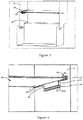
Figure 1 is a frontal representation of the inner receptacle of the cooling appliance subject of the invention, of which a representative configuration is used. -
Figure 2 is an independent perspective representation of the shelf and drawer of the cooling appliance shown inFigure 1 . -
Figure 3 is a perspective representation of a cooling appliance in which inner receptacle there is no drawer, showing the shelf and the guide. -
Figure 4 is an approached representation of the shelf in the configuration shown inFigure 4 . -
Figure 5 is an approached perspective representation from behind of a representative configuration subject of the invention, in which the shelf and the drawer are connected together. -
Figure 6 is a perspective representation of the hanging element used inFigure 5 . -
Figure 7 is a perspective representation of a cooling appliance drawer configured appropriately to the hanging element subject of the invention. - In
Figure 1 , the inner receptacle (10) of the cooling appliance including a representative configuration of a hanging element (40) subject of the invention is represented perspectively. The inner receptacle (10) has a shelf (30) extending between respectively one lateral wall (12) and two overlapping storing units consisting of a drawer (20) provided beneath the shelf. Over the inner receptacle (10) in the part corresponding to the compressor chamber (not shown in the figure) there is provided a step (16). The upper drawer (20) is seated on the step (16). - In
Figure 2 , the drawer (20) and the shelf (30) above it are represented separately in perspective. The shelf (30) covers completely the upper part of the drawer (20). Respectively one hanging element (40) is attached to both lateral edges (32) of the drawer (30) by means of an upper guide (42). Within the lower guide (44) of the hanging element (40), the drawer (20) passes through an edge border (26). The hanging element (40) is aligned parallelly so as to rest against the lateral wall (12). - As shown in
Figure 3 , the lower guide (42) of the hanging element (40) is attached all along to the lateral edge (32) of the shelf (30) by close fit. As shown inFigure 4 , both upper guide (42) and lower guide (44) are in a U-section form. The length of the lower guide (44) is shorter than the length of the upper guide (42). The lower guide (44) is aligned in a manner centering the upper guide (42). The upper and the lower guide (42, 44) have a bridging element (45) joining adjacent ends. The adjacent edges of the lower and the upper guide (42, 44) and the bridging element (45) joining them form a U-section form in a direction opposite the upper and the lower guide (42, 44). The hanging element (40) is attached from this bridging element (45) forming an upsetting, to a supporting projection (14) extending out of the lateral wall (12). Respectively one mounting element (46) is formed in the form of two protrusions outward from the bridging element (45) such that it prevents the hanging element (40) to be dislocated. The distance between the protrusions of the mounting element (46) is equal to the length of the supporting projection (14). So, by holding to the supporting projection (14) by both ends, the mounting element (46) prevents the advancing movement of the hanging element (40). - In
figure 5 , the hanging element (40) is represented in a position at which the drawer (20) is placed in the lower guide (44). The upper guide (42) holds tightly a shelf (30) that is passed through its opening (422) and compressed between the lower alt holding extension (421) and the upper holding extension (423). To provide this, the distance between the opposite upper holding extension (423) and lower holding extension (421) of the upper guide (42) in U-section form is substantially equal to the thickness of the shelf (30). The drawer (20) as shownFigure 7 is passed from an opening (442) of the lower guide (44) to the lower guide (44), from respectively one of its borders (26) extending outwardly on its lateral walls (22). An opposite lower holding extension (442) that possesses the lower guide (44) in U-section form together with its other edge adjacent to the bridging element (45), receives the border (26) such that it slides freely. Due to the fact that the mounting elements (46) hold the supporting projection (14) by two ends, the forces like friction etc. occurring when the drawer (20) slides within the lower guide (44) are met by the hanging element (40) and a rigid structure is obtained. - By providing the hanging element (40) at both lateral edges (32) of the shelf (30), it is enabled that the drawer (20) is slidingly transported so as to be guided from its border (26) in both of its edges.
REFERENCE NUMBERS 10 Inner receptacle 40 Hanging element 12 Lateral wall 42 Upper guide 14 Supporting projection 421 Lower holding extension 16 Step 422 Opening 20 Drawer 423 Upper holding extension 22 Lateral wall 44 Lower guide 24 Front wall 441 Lower holding extension 25 Handle 442 Opening 26 Border 45 Bridging element 261 Front edge 46 Mounting element 262 Stopper 30 Shelf 32 Lateral edge
Claims (8)
- Cooling appliance, comprising
a thermally insulated inner receptacle (10);
a drawer (20) provided in the inner receptacle (10) so as to be withdrawable and in which elements to be cooled are to be placed;
a shelf (30) positioned in the inner receptacle (10) so as to be withdrawable such that it covers at least partly the upper part of the drawer (20), and
a hanging element (40) having an upper guide (42) attached to the shelf (30) by a lateral edge (32) and a lower guide (44) attached to the drawer (20) by an edge border (26) by extending under the upper guide (42) and integrated to the upper guide (42), wherein a bridging element (45) provided between the upper and lower guides (42, 44) by respectively one end so as to provide that they are positioned at a distance to each other, characterized in that the adjacent edges of upper and lower guides (42, 44) and the bridging element (45) joining them form a U-section, wherein said U-section is formed in a direction opposite the upper and lower guides (42, 44), and that the hanging element (40) is attached by the bridging element (45) to a supporting projection (14) out of a lateral wall (12) of the inner receptacle (10). - Cooling appliance according to claim 1, wherein the hanging element (40) is fastened to the inner receptacle (10) by its outer surface.
- Cooling appliance according to claim 2, wherein the hanging element (40) comprises a mounting element (46) extending from its outer surface to the inner receptacle (10).
- Cooling appliance according to claim 1 and 3, wherein the mounting element (46) is formed on the bridging element (45).
- Cooling appliance according to anyone of the preceding claims, characterised in that the upper and the lower guide (42, 44) have a U-like section.
- Cooling appliance according to anyone of the preceding claims, wherein the upper and the lower guide (42, 44) are aligned to a lateral wall (12) of the inner receptacle (10).
- Cooling appliance according to anyone of the preceding claims, wherein Z the hanging element (40) is made as monoblock plastic injection.
- Cooling appliance according to anyone of the preceding claims, wherein the upper guide (42) extends along the lateral edge (32) of the shelf (30).
Applications Claiming Priority (2)
| Application Number | Priority Date | Filing Date | Title |
|---|---|---|---|
| TR201215670 | 2012-12-31 | ||
| PCT/EP2013/077217 WO2014102120A1 (en) | 2012-12-31 | 2013-12-18 | Cooling appliance having a drawer guide |
Publications (2)
| Publication Number | Publication Date |
|---|---|
| EP2938949A1 EP2938949A1 (en) | 2015-11-04 |
| EP2938949B1 true EP2938949B1 (en) | 2020-09-16 |
Family
ID=49880755
Family Applications (1)
| Application Number | Title | Priority Date | Filing Date |
|---|---|---|---|
| EP13811912.8A Active EP2938949B1 (en) | 2012-12-31 | 2013-12-18 | Cooling appliance having a drawer guide |
Country Status (2)
| Country | Link |
|---|---|
| EP (1) | EP2938949B1 (en) |
| WO (1) | WO2014102120A1 (en) |
Families Citing this family (3)
| Publication number | Priority date | Publication date | Assignee | Title |
|---|---|---|---|---|
| EP4060267B1 (en) * | 2021-03-15 | 2026-04-08 | Beko Europe Management S.r.l. | Guiding structure for a drawer and appliance including the guiding structure |
| US12152831B2 (en) | 2021-04-06 | 2024-11-26 | Electrolux Home Products, Inc. | Crisper assembly with slide out shelf |
| DE102021204418A1 (en) * | 2021-05-03 | 2022-11-03 | BSH Hausgeräte GmbH | Storage arrangement with a profile rail made of metal, and domestic refrigeration device |
Family Cites Families (4)
| Publication number | Priority date | Publication date | Assignee | Title |
|---|---|---|---|---|
| US4173378A (en) * | 1978-07-31 | 1979-11-06 | White Consolidated Industries, Inc. | Refrigerator sealed food storage drawer |
| US4936641A (en) * | 1988-11-07 | 1990-06-26 | Whirlpool Corporation | Mounting system for an adjustable refrigerator article supporting member |
| US6565169B1 (en) * | 2000-11-03 | 2003-05-20 | Comercial Acros Whirpool, S.A. De C.V. | Double crisper drawer for a refrigerator |
| DE10339942A1 (en) * | 2003-08-29 | 2005-03-24 | BSH Bosch und Siemens Hausgeräte GmbH | Withdrawable storage container for refrigeration appliance has rail system beneath shelf into which container is slid |
-
2013
- 2013-12-18 EP EP13811912.8A patent/EP2938949B1/en active Active
- 2013-12-18 WO PCT/EP2013/077217 patent/WO2014102120A1/en not_active Ceased
Non-Patent Citations (1)
| Title |
|---|
| None * |
Also Published As
| Publication number | Publication date |
|---|---|
| WO2014102120A1 (en) | 2014-07-03 |
| EP2938949A1 (en) | 2015-11-04 |
Similar Documents
| Publication | Publication Date | Title |
|---|---|---|
| US7270385B2 (en) | Spill proof shelf assembly method and structure | |
| US9250010B2 (en) | Refrigerator shelf with glass receiving slot | |
| EP2551617B1 (en) | Refrigerator | |
| US9803913B2 (en) | Tiered storage system for refrigerator door | |
| US9182168B2 (en) | Compartmentalized storage container | |
| US8840205B2 (en) | Refrigerator appliance and a shelf assembly for the same | |
| US6565169B1 (en) | Double crisper drawer for a refrigerator | |
| US20090188877A1 (en) | Full extension refrigerator shelf and basket system | |
| US20190339000A1 (en) | Refrigerator | |
| US20130257253A1 (en) | Crisper pan system for a domestic refrigerator | |
| CN101963433A (en) | Refrigerator drawer and refrigerator having the same | |
| US6231146B1 (en) | Refrigerator door bottom storage module assembly | |
| US20080054772A1 (en) | Support assembly for an appliance storage bin or storage shelf | |
| US10451338B2 (en) | Door storage bin assembly for a refrigerator | |
| US20160131416A1 (en) | Liner shelf support structures for refrigerators and freezers | |
| US9513047B2 (en) | Door module assembly for a refrigerator appliance | |
| CN105492848B (en) | The Domestic refrigerator that can exit formula guide rail for box arranged with internal container and wherein | |
| EP2049853B1 (en) | A refrigerator | |
| EP2938949A1 (en) | Cooling appliance having a drawer guide | |
| EP3141850B1 (en) | A shelf system | |
| US20170370633A1 (en) | Regrigerator with glass shelves | |
| EP2870421B1 (en) | Refrigerator assembly with soft freeze zone | |
| EP2630426B1 (en) | Refrigerator and stopping arrangement of refrigerator shelf | |
| US20120325827A1 (en) | Refrigerator with a slide-out pan assembly | |
| CN205980552U (en) | Domestic refrigerator with pull out casket |
Legal Events
| Date | Code | Title | Description |
|---|---|---|---|
| PUAI | Public reference made under article 153(3) epc to a published international application that has entered the european phase |
Free format text: ORIGINAL CODE: 0009012 |
|
| 17P | Request for examination filed |
Effective date: 20150731 |
|
| AK | Designated contracting states |
Kind code of ref document: A1 Designated state(s): AL AT BE BG CH CY CZ DE DK EE ES FI FR GB GR HR HU IE IS IT LI LT LU LV MC MK MT NL NO PL PT RO RS SE SI SK SM TR |
|
| AX | Request for extension of the european patent |
Extension state: BA ME |
|
| DAX | Request for extension of the european patent (deleted) | ||
| GRAP | Despatch of communication of intention to grant a patent |
Free format text: ORIGINAL CODE: EPIDOSNIGR1 |
|
| STAA | Information on the status of an ep patent application or granted ep patent |
Free format text: STATUS: GRANT OF PATENT IS INTENDED |
|
| INTG | Intention to grant announced |
Effective date: 20200515 |
|
| GRAS | Grant fee paid |
Free format text: ORIGINAL CODE: EPIDOSNIGR3 |
|
| GRAA | (expected) grant |
Free format text: ORIGINAL CODE: 0009210 |
|
| STAA | Information on the status of an ep patent application or granted ep patent |
Free format text: STATUS: THE PATENT HAS BEEN GRANTED |
|
| AK | Designated contracting states |
Kind code of ref document: B1 Designated state(s): AL AT BE BG CH CY CZ DE DK EE ES FI FR GB GR HR HU IE IS IT LI LT LU LV MC MK MT NL NO PL PT RO RS SE SI SK SM TR |
|
| REG | Reference to a national code |
Ref country code: GB Ref legal event code: FG4D |
|
| REG | Reference to a national code |
Ref country code: CH Ref legal event code: EP |
|
| REG | Reference to a national code |
Ref country code: DE Ref legal event code: R096 Ref document number: 602013072624 Country of ref document: DE |
|
| REG | Reference to a national code |
Ref country code: IE Ref legal event code: FG4D |
|
| REG | Reference to a national code |
Ref country code: AT Ref legal event code: REF Ref document number: 1314528 Country of ref document: AT Kind code of ref document: T Effective date: 20201015 |
|
| PG25 | Lapsed in a contracting state [announced via postgrant information from national office to epo] |
Ref country code: BG Free format text: LAPSE BECAUSE OF FAILURE TO SUBMIT A TRANSLATION OF THE DESCRIPTION OR TO PAY THE FEE WITHIN THE PRESCRIBED TIME-LIMIT Effective date: 20201216 Ref country code: HR Free format text: LAPSE BECAUSE OF FAILURE TO SUBMIT A TRANSLATION OF THE DESCRIPTION OR TO PAY THE FEE WITHIN THE PRESCRIBED TIME-LIMIT Effective date: 20200916 Ref country code: SE Free format text: LAPSE BECAUSE OF FAILURE TO SUBMIT A TRANSLATION OF THE DESCRIPTION OR TO PAY THE FEE WITHIN THE PRESCRIBED TIME-LIMIT Effective date: 20200916 Ref country code: NO Free format text: LAPSE BECAUSE OF FAILURE TO SUBMIT A TRANSLATION OF THE DESCRIPTION OR TO PAY THE FEE WITHIN THE PRESCRIBED TIME-LIMIT Effective date: 20201216 Ref country code: GR Free format text: LAPSE BECAUSE OF FAILURE TO SUBMIT A TRANSLATION OF THE DESCRIPTION OR TO PAY THE FEE WITHIN THE PRESCRIBED TIME-LIMIT Effective date: 20201217 Ref country code: FI Free format text: LAPSE BECAUSE OF FAILURE TO SUBMIT A TRANSLATION OF THE DESCRIPTION OR TO PAY THE FEE WITHIN THE PRESCRIBED TIME-LIMIT Effective date: 20200916 |
|
| REG | Reference to a national code |
Ref country code: AT Ref legal event code: MK05 Ref document number: 1314528 Country of ref document: AT Kind code of ref document: T Effective date: 20200916 |
|
| REG | Reference to a national code |
Ref country code: NL Ref legal event code: MP Effective date: 20200916 |
|
| PG25 | Lapsed in a contracting state [announced via postgrant information from national office to epo] |
Ref country code: RS Free format text: LAPSE BECAUSE OF FAILURE TO SUBMIT A TRANSLATION OF THE DESCRIPTION OR TO PAY THE FEE WITHIN THE PRESCRIBED TIME-LIMIT Effective date: 20200916 Ref country code: LV Free format text: LAPSE BECAUSE OF FAILURE TO SUBMIT A TRANSLATION OF THE DESCRIPTION OR TO PAY THE FEE WITHIN THE PRESCRIBED TIME-LIMIT Effective date: 20200916 |
|
| REG | Reference to a national code |
Ref country code: LT Ref legal event code: MG4D |
|
| PG25 | Lapsed in a contracting state [announced via postgrant information from national office to epo] |
Ref country code: CZ Free format text: LAPSE BECAUSE OF FAILURE TO SUBMIT A TRANSLATION OF THE DESCRIPTION OR TO PAY THE FEE WITHIN THE PRESCRIBED TIME-LIMIT Effective date: 20200916 Ref country code: EE Free format text: LAPSE BECAUSE OF FAILURE TO SUBMIT A TRANSLATION OF THE DESCRIPTION OR TO PAY THE FEE WITHIN THE PRESCRIBED TIME-LIMIT Effective date: 20200916 Ref country code: RO Free format text: LAPSE BECAUSE OF FAILURE TO SUBMIT A TRANSLATION OF THE DESCRIPTION OR TO PAY THE FEE WITHIN THE PRESCRIBED TIME-LIMIT Effective date: 20200916 Ref country code: SM Free format text: LAPSE BECAUSE OF FAILURE TO SUBMIT A TRANSLATION OF THE DESCRIPTION OR TO PAY THE FEE WITHIN THE PRESCRIBED TIME-LIMIT Effective date: 20200916 Ref country code: NL Free format text: LAPSE BECAUSE OF FAILURE TO SUBMIT A TRANSLATION OF THE DESCRIPTION OR TO PAY THE FEE WITHIN THE PRESCRIBED TIME-LIMIT Effective date: 20200916 Ref country code: LT Free format text: LAPSE BECAUSE OF FAILURE TO SUBMIT A TRANSLATION OF THE DESCRIPTION OR TO PAY THE FEE WITHIN THE PRESCRIBED TIME-LIMIT Effective date: 20200916 Ref country code: PT Free format text: LAPSE BECAUSE OF FAILURE TO SUBMIT A TRANSLATION OF THE DESCRIPTION OR TO PAY THE FEE WITHIN THE PRESCRIBED TIME-LIMIT Effective date: 20210118 |
|
| PG25 | Lapsed in a contracting state [announced via postgrant information from national office to epo] |
Ref country code: AL Free format text: LAPSE BECAUSE OF FAILURE TO SUBMIT A TRANSLATION OF THE DESCRIPTION OR TO PAY THE FEE WITHIN THE PRESCRIBED TIME-LIMIT Effective date: 20200916 Ref country code: AT Free format text: LAPSE BECAUSE OF FAILURE TO SUBMIT A TRANSLATION OF THE DESCRIPTION OR TO PAY THE FEE WITHIN THE PRESCRIBED TIME-LIMIT Effective date: 20200916 Ref country code: ES Free format text: LAPSE BECAUSE OF FAILURE TO SUBMIT A TRANSLATION OF THE DESCRIPTION OR TO PAY THE FEE WITHIN THE PRESCRIBED TIME-LIMIT Effective date: 20200916 Ref country code: IS Free format text: LAPSE BECAUSE OF FAILURE TO SUBMIT A TRANSLATION OF THE DESCRIPTION OR TO PAY THE FEE WITHIN THE PRESCRIBED TIME-LIMIT Effective date: 20210116 Ref country code: PL Free format text: LAPSE BECAUSE OF FAILURE TO SUBMIT A TRANSLATION OF THE DESCRIPTION OR TO PAY THE FEE WITHIN THE PRESCRIBED TIME-LIMIT Effective date: 20200916 |
|
| REG | Reference to a national code |
Ref country code: DE Ref legal event code: R097 Ref document number: 602013072624 Country of ref document: DE |
|
| PG25 | Lapsed in a contracting state [announced via postgrant information from national office to epo] |
Ref country code: SK Free format text: LAPSE BECAUSE OF FAILURE TO SUBMIT A TRANSLATION OF THE DESCRIPTION OR TO PAY THE FEE WITHIN THE PRESCRIBED TIME-LIMIT Effective date: 20200916 |
|
| PLBE | No opposition filed within time limit |
Free format text: ORIGINAL CODE: 0009261 |
|
| STAA | Information on the status of an ep patent application or granted ep patent |
Free format text: STATUS: NO OPPOSITION FILED WITHIN TIME LIMIT |
|
| REG | Reference to a national code |
Ref country code: CH Ref legal event code: PL |
|
| 26N | No opposition filed |
Effective date: 20210617 |
|
| GBPC | Gb: european patent ceased through non-payment of renewal fee |
Effective date: 20201218 |
|
| PG25 | Lapsed in a contracting state [announced via postgrant information from national office to epo] |
Ref country code: SI Free format text: LAPSE BECAUSE OF FAILURE TO SUBMIT A TRANSLATION OF THE DESCRIPTION OR TO PAY THE FEE WITHIN THE PRESCRIBED TIME-LIMIT Effective date: 20200916 Ref country code: DK Free format text: LAPSE BECAUSE OF FAILURE TO SUBMIT A TRANSLATION OF THE DESCRIPTION OR TO PAY THE FEE WITHIN THE PRESCRIBED TIME-LIMIT Effective date: 20200916 Ref country code: MC Free format text: LAPSE BECAUSE OF FAILURE TO SUBMIT A TRANSLATION OF THE DESCRIPTION OR TO PAY THE FEE WITHIN THE PRESCRIBED TIME-LIMIT Effective date: 20200916 |
|
| REG | Reference to a national code |
Ref country code: BE Ref legal event code: MM Effective date: 20201231 |
|
| PG25 | Lapsed in a contracting state [announced via postgrant information from national office to epo] |
Ref country code: IT Free format text: LAPSE BECAUSE OF FAILURE TO SUBMIT A TRANSLATION OF THE DESCRIPTION OR TO PAY THE FEE WITHIN THE PRESCRIBED TIME-LIMIT Effective date: 20200916 Ref country code: IE Free format text: LAPSE BECAUSE OF NON-PAYMENT OF DUE FEES Effective date: 20201218 Ref country code: FR Free format text: LAPSE BECAUSE OF NON-PAYMENT OF DUE FEES Effective date: 20201231 Ref country code: LU Free format text: LAPSE BECAUSE OF NON-PAYMENT OF DUE FEES Effective date: 20201218 |
|
| PG25 | Lapsed in a contracting state [announced via postgrant information from national office to epo] |
Ref country code: CH Free format text: LAPSE BECAUSE OF NON-PAYMENT OF DUE FEES Effective date: 20201231 Ref country code: GB Free format text: LAPSE BECAUSE OF NON-PAYMENT OF DUE FEES Effective date: 20201218 Ref country code: LI Free format text: LAPSE BECAUSE OF NON-PAYMENT OF DUE FEES Effective date: 20201231 |
|
| PG25 | Lapsed in a contracting state [announced via postgrant information from national office to epo] |
Ref country code: IS Free format text: LAPSE BECAUSE OF FAILURE TO SUBMIT A TRANSLATION OF THE DESCRIPTION OR TO PAY THE FEE WITHIN THE PRESCRIBED TIME-LIMIT Effective date: 20210116 Ref country code: TR Free format text: LAPSE BECAUSE OF FAILURE TO SUBMIT A TRANSLATION OF THE DESCRIPTION OR TO PAY THE FEE WITHIN THE PRESCRIBED TIME-LIMIT Effective date: 20200916 Ref country code: MT Free format text: LAPSE BECAUSE OF FAILURE TO SUBMIT A TRANSLATION OF THE DESCRIPTION OR TO PAY THE FEE WITHIN THE PRESCRIBED TIME-LIMIT Effective date: 20200916 Ref country code: CY Free format text: LAPSE BECAUSE OF FAILURE TO SUBMIT A TRANSLATION OF THE DESCRIPTION OR TO PAY THE FEE WITHIN THE PRESCRIBED TIME-LIMIT Effective date: 20200916 |
|
| PG25 | Lapsed in a contracting state [announced via postgrant information from national office to epo] |
Ref country code: MK Free format text: LAPSE BECAUSE OF FAILURE TO SUBMIT A TRANSLATION OF THE DESCRIPTION OR TO PAY THE FEE WITHIN THE PRESCRIBED TIME-LIMIT Effective date: 20200916 |
|
| PG25 | Lapsed in a contracting state [announced via postgrant information from national office to epo] |
Ref country code: BE Free format text: LAPSE BECAUSE OF NON-PAYMENT OF DUE FEES Effective date: 20201231 |
|
| PGFP | Annual fee paid to national office [announced via postgrant information from national office to epo] |
Ref country code: DE Payment date: 20251231 Year of fee payment: 13 |