EP2938896B1 - Tolerance ring with discrete tolerance ring panels - Google Patents
Tolerance ring with discrete tolerance ring panels Download PDFInfo
- Publication number
- EP2938896B1 EP2938896B1 EP13814884.6A EP13814884A EP2938896B1 EP 2938896 B1 EP2938896 B1 EP 2938896B1 EP 13814884 A EP13814884 A EP 13814884A EP 2938896 B1 EP2938896 B1 EP 2938896B1
- Authority
- EP
- European Patent Office
- Prior art keywords
- tolerance ring
- ring
- panels
- tolerance
- assembly
- Prior art date
- Legal status (The legal status is an assumption and is not a legal conclusion. Google has not performed a legal analysis and makes no representation as to the accuracy of the status listed.)
- Active
Links
Images




Classifications
-
- G—PHYSICS
- G11—INFORMATION STORAGE
- G11B—INFORMATION STORAGE BASED ON RELATIVE MOVEMENT BETWEEN RECORD CARRIER AND TRANSDUCER
- G11B5/00—Recording by magnetisation or demagnetisation of a record carrier; Reproducing by magnetic means; Record carriers therefor
- G11B5/48—Disposition or mounting of heads or head supports relative to record carriers ; arrangements of heads, e.g. for scanning the record carrier to increase the relative speed
- G11B5/4806—Disposition or mounting of heads or head supports relative to record carriers ; arrangements of heads, e.g. for scanning the record carrier to increase the relative speed specially adapted for disk drive assemblies, e.g. assembly prior to operation, hard or flexible disk drives
- G11B5/4813—Mounting or aligning of arm assemblies, e.g. actuator arm supported by bearings, multiple arm assemblies, arm stacks or multiple heads on single arm
-
- F—MECHANICAL ENGINEERING; LIGHTING; HEATING; WEAPONS; BLASTING
- F16—ENGINEERING ELEMENTS AND UNITS; GENERAL MEASURES FOR PRODUCING AND MAINTAINING EFFECTIVE FUNCTIONING OF MACHINES OR INSTALLATIONS; THERMAL INSULATION IN GENERAL
- F16C—SHAFTS; FLEXIBLE SHAFTS; ELEMENTS OR CRANKSHAFT MECHANISMS; ROTARY BODIES OTHER THAN GEARING ELEMENTS; BEARINGS
- F16C27/00—Elastic or yielding bearings or bearing supports, for exclusively rotary movement
-
- F—MECHANICAL ENGINEERING; LIGHTING; HEATING; WEAPONS; BLASTING
- F16—ENGINEERING ELEMENTS AND UNITS; GENERAL MEASURES FOR PRODUCING AND MAINTAINING EFFECTIVE FUNCTIONING OF MACHINES OR INSTALLATIONS; THERMAL INSULATION IN GENERAL
- F16D—COUPLINGS FOR TRANSMITTING ROTATION; CLUTCHES; BRAKES
- F16D1/00—Couplings for rigidly connecting two coaxial shafts or other movable machine elements
- F16D1/06—Couplings for rigidly connecting two coaxial shafts or other movable machine elements for attachment of a member on a shaft or on a shaft-end
- F16D1/08—Couplings for rigidly connecting two coaxial shafts or other movable machine elements for attachment of a member on a shaft or on a shaft-end with clamping hub; with hub and longitudinal key
- F16D1/0829—Couplings for rigidly connecting two coaxial shafts or other movable machine elements for attachment of a member on a shaft or on a shaft-end with clamping hub; with hub and longitudinal key with radial loading of both hub and shaft by an intermediate ring or sleeve
-
- F—MECHANICAL ENGINEERING; LIGHTING; HEATING; WEAPONS; BLASTING
- F16—ENGINEERING ELEMENTS AND UNITS; GENERAL MEASURES FOR PRODUCING AND MAINTAINING EFFECTIVE FUNCTIONING OF MACHINES OR INSTALLATIONS; THERMAL INSULATION IN GENERAL
- F16D—COUPLINGS FOR TRANSMITTING ROTATION; CLUTCHES; BRAKES
- F16D1/00—Couplings for rigidly connecting two coaxial shafts or other movable machine elements
- F16D1/06—Couplings for rigidly connecting two coaxial shafts or other movable machine elements for attachment of a member on a shaft or on a shaft-end
- F16D1/08—Couplings for rigidly connecting two coaxial shafts or other movable machine elements for attachment of a member on a shaft or on a shaft-end with clamping hub; with hub and longitudinal key
- F16D1/0829—Couplings for rigidly connecting two coaxial shafts or other movable machine elements for attachment of a member on a shaft or on a shaft-end with clamping hub; with hub and longitudinal key with radial loading of both hub and shaft by an intermediate ring or sleeve
- F16D1/0835—Couplings for rigidly connecting two coaxial shafts or other movable machine elements for attachment of a member on a shaft or on a shaft-end with clamping hub; with hub and longitudinal key with radial loading of both hub and shaft by an intermediate ring or sleeve due to the elasticity of the ring or sleeve
-
- G—PHYSICS
- G11—INFORMATION STORAGE
- G11B—INFORMATION STORAGE BASED ON RELATIVE MOVEMENT BETWEEN RECORD CARRIER AND TRANSDUCER
- G11B5/00—Recording by magnetisation or demagnetisation of a record carrier; Reproducing by magnetic means; Record carriers therefor
- G11B5/48—Disposition or mounting of heads or head supports relative to record carriers ; arrangements of heads, e.g. for scanning the record carrier to increase the relative speed
- G11B5/54—Disposition or mounting of heads or head supports relative to record carriers ; arrangements of heads, e.g. for scanning the record carrier to increase the relative speed with provision for moving the head into or out of its operative position or across tracks
- G11B5/55—Track change, selection or acquisition by displacement of the head
- G11B5/5521—Track change, selection or acquisition by displacement of the head across disk tracks
- G11B5/5569—Track change, selection or acquisition by displacement of the head across disk tracks details of specially adapted mobile parts, e.g. electromechanical control devices
-
- F—MECHANICAL ENGINEERING; LIGHTING; HEATING; WEAPONS; BLASTING
- F16—ENGINEERING ELEMENTS AND UNITS; GENERAL MEASURES FOR PRODUCING AND MAINTAINING EFFECTIVE FUNCTIONING OF MACHINES OR INSTALLATIONS; THERMAL INSULATION IN GENERAL
- F16C—SHAFTS; FLEXIBLE SHAFTS; ELEMENTS OR CRANKSHAFT MECHANISMS; ROTARY BODIES OTHER THAN GEARING ELEMENTS; BEARINGS
- F16C2370/00—Apparatus relating to physics, e.g. instruments
- F16C2370/12—Hard disk drives or the like
-
- Y—GENERAL TAGGING OF NEW TECHNOLOGICAL DEVELOPMENTS; GENERAL TAGGING OF CROSS-SECTIONAL TECHNOLOGIES SPANNING OVER SEVERAL SECTIONS OF THE IPC; TECHNICAL SUBJECTS COVERED BY FORMER USPC CROSS-REFERENCE ART COLLECTIONS [XRACs] AND DIGESTS
- Y10—TECHNICAL SUBJECTS COVERED BY FORMER USPC
- Y10T—TECHNICAL SUBJECTS COVERED BY FORMER US CLASSIFICATION
- Y10T403/00—Joints and connections
- Y10T403/70—Interfitted members
- Y10T403/7047—Radially interposed shim or bushing
- Y10T403/7051—Wedging or camming
Definitions
- the present invention is directed generally to tolerance rings, and particularly to tolerance rings for actuator arms within hard disk drives.
- the present invention relates to tolerance ring assemblies, wherein a tolerance ring provides an interference fit between parts of an assembly, in which a first part has a cylindrical portion located in a cylindrical bore of a second part.
- the present disclosure relates to assemblies having a tolerance ring that provides an interference fit between a cylindrical component such as a shaft or a bearing and a housing for the shaft.
- Tolerance rings may be used to provide an interference fit between parts required to transmit torque. Tolerance rings provide a low cost means of providing an interference fit between parts that may not be machined to exact dimensions. Tolerance rings have a number of other potential advantages, such as compensating for different linear coefficients of expansion between the parts, allowing rapid apparatus assembly, and durability.
- a tolerance ring generally comprises a strip of resilient material, for example a metal such as spring steel, the ends of which are brought together to form a ring.
- a band of protrusions extend radially outwards from the ring, or radially inwards towards the center of the ring.
- the protrusions are formations, possibly regular formations, such as corrugations, ridges or waves.
- the protrusions When the ring is located in the annular space between, for example, a shaft and a bore in a housing in which the shaft is located, the protrusions are compressed. Each protrusion acts as a spring and exerts a radial force against the shaft and the surface of the bore, providing an interference fit between the shaft and the housing. Rotation of the housing or the shaft will produce similar rotation in the other of the shaft or the housing, as torque is transmitted by the tolerance ring.
- the band of protrusions is axially flanked by annular regions of the ring that have no formations (known in the art as "unformed regions" of the tolerance ring).
- tolerance rings usually comprise a strip of resilient material that is curved to allow the easy formation of a ring by overlapping the ends of the strip, a tolerance ring may also be manufactured as an annular band.
- tolerance ring as used hereafter includes both types of tolerance ring.
- shaft as used hereafter includes any assembly component with a cylindrical portion, such as a shaft or a bearing.
- US 4 569 614 A refers to a coupling for fastening two members whose opposed faces keep an equal gap and are free to relatively displace to the left or right, wherein a wedge inclining with an angle narrower than the friction angle to osculate each of the opposing face of the members, is capable of wedging the opposing faces by relative displacement of the members toward the rising side of the wedge.
- the coupling is arranged on the left and right respectively in the direction of relative displacement of the members, so that two members can be coupled plainly, rigidly and free from lowering of the axis strength, permitting an easy phase adjustment or dividing or the like.
- EP 1 759 955 A2 refers to a bush for insertion between two relatively moveable inter-engaging inner and outer members, the bush having a portion which is arranged to accommodate expansion and/or contraction between the members under varying temperature load.
- the portion may be corrugated, for example and/or have a thickness in section which is less than other parts of the bush.
- the members may be inner and outer steering column members for a vehicle.
- DE 10 2011 015 199 A1 refers to a device having an azimuth transmission, and an azimuth drive comprising an output i.e. shaft, that is connected with the transmission, where the drive is designed as a frequency-controlled electric motor.
- a torque limiter is arranged between the drive and the transmission in an inner groove of a plug-in sleeve and provided for limiting torque acting on the drive.
- the torque limiter is designed as a casing and connected to an insertion part that is connected with the output of the drive or the transmission in a torque-proof manner.
- US 6 480 363 B1 relates to an improved pivot assembly for a hard disk drive actuator.
- tolerance rings and particularly, to tolerance rings that can be installed within a hard disk drive between a pivot assembly and a bore formed in an actuator arm.
- a tolerance ring can be fitted around the pivot assembly and then this assembly can be inserted into the bore.
- the tolerance ring can be inserted into the bore and the pivot can be inserted into the tolerance ring.
- the waves nearest to the gap tend to be the weakest, i.e., least stiff, since the waves have a gap on one side and material on the other and the remaining waves in the tolerance ring are flanked by material on both sides.
- This variation in stiffness can cause performance variables, e.g., resonance and alignment, to be very dependent on a position of the gap in the hard disk drive assembly. Attempting to optimize the gap location for one performance parameter can adversely affect other performance parameters. This, in turn, can compromise overall performance.
- a tolerance ring according to one or more of the embodiments described herein is defined in claim 1. It includes a plurality discrete tolerance ring panels that can be equally spaced around the circumference of the tolerance ring and the tolerance ring can be symmetric about an axis passing through the center of the tolerance ring and a gap in the tolerance ring.
- the arrangement provided by the tolerance ring panels disclosed herein can provide a tolerance ring having a resonant frequency and stiffness that do not substantially vary circumferentially around the tolerance ring. As such, the tolerance ring can maintain the pivot assembly in alignment within the bore and can substantially prevent any rocking of the post within the bore under normal operational loads in nearly any radial direction.
- the hard disk drive assembly 100 can include an actuator arm 102 for a hard disk drive and a pivot assembly 104.
- the actuator arm 102 can include a proximal end 110 and a distal end 112.
- a plurality of read/write heads 114 can extend from the distal end 112 of the actuator arm 102.
- the actuator arm 102 can be formed with a bore 116 near the proximal end 110 of the actuator arm 102.
- FIG. 1 further indicates that the pivot assembly 104 can include a pivot 120 and a tolerance ring 122.
- the pivot 120 can include an inner member 124 and an outer member 126, and the outer member 126 can rotate with respect to the inner member 124.
- the tolerance ring 122 can fit around the pivot 120 and then, the pivot assembly 104 can be installed within the bore 116. In another aspect, the tolerance ring 122 can be placed within the bore 116 and the pivot 120 can be inserted into the tolerance ring 122. The tolerance ring 122 can establish an interference fit between the outer member 126 of the pivot 120 and the bore 116 of the actuator arm 102. As such, the actuator arm 102 can rotate with the outer member 126 of the pivot 120 around the inner member 124 of the pivot 120.
- the tolerance ring 122 can be installed within the bore 116 between an outer component, the actuator arm 102, and an inner component, the pivot 120.
- no portion of the tolerance ring 122 extends beyond the top or bottom of the bore and the tolerance ring 122 can be completely contained within the bore 116.
- a portion of the tolerance ring 122 e.g., a top, a bottom, a structure on a top, a structure on a bottom, or a combination thereof, can extend from the bore.
- the tolerance ring 122 can be configured to engage the inner wall of the bore 116 and the outer wall of the pivot 120 in order to maintain the pivot 120 within the actuator arm 102 in an interference fit.
- the tolerance ring 122 can account for dimensional variations by expanding around the pivot 120 as it is installed thereon and then, at least partially deforming, or compressing, within the bore 116 during installation.
- the tolerance ring 122 is configured to be deployed in an interference fit between an inner component and an outer component to provide torque coupling between an inner component and an outer component.
- the inner component can be the pivot assembly, described above, and the outer component can be the actuator arm for the hard disk drive assembly, also described above.
- the tolerance ring 122 can include a plurality of discrete tolerance ring panels 300.
- Each tolerance ring panel 300 can include an arcuate sidewall 302 having a top 304 and a bottom 306.
- the arcuate sidewall 302 of each tolerance ring panel 300 can also include an upper flange portion 308 that can extend from the top 304 of the arcuate sidewall 302 and a lower flange portion 310 that can extend from the bottom 306 of the arcuate sidewall 302.
- the tolerance ring panels 300 are spaced apart circumferentially to form a plurality of gaps 312 within the tolerance ring 122.
- Each gap 312 can include a circumferential width, W G , and W G is uniform around the tolerance ring 122.
- W G can vary around the tolerance ring 122.
- each tolerance ring panel 300 can have a circumferential width, W P .
- W P can be uniform around the tolerance ring.
- W P can vary around the tolerance ring.
- W G can be ⁇ 400% W P , such as ⁇ 300% W P , ⁇ 200% W P , ⁇ 100% W P , or ⁇ 50% W P. Further, W G can be ⁇ 1% W P , such as ⁇ 5% W P , or ⁇ 10% W P. In another aspect, W G can be within a range between and including any of the values of W G described herein. For example, W G can be ⁇ 400% W P and ⁇ 1% W P , such as ⁇ 400% W P and ⁇ 5% W P , ⁇ 400% W P and or ⁇ 10% W P.
- W G can be ⁇ 300% W P and ⁇ 1% W P , such as ⁇ 300% W P and ⁇ 5% W P , ⁇ 300% W P and or ⁇ 10% W P. Further, W G can be ⁇ 200% W P and ⁇ 1% W P , such as ⁇ 200% W P and ⁇ 5% W P , ⁇ 200% W P and or ⁇ 10% W P . Still further, W G can be ⁇ 150% W P and ⁇ 1% W P , such as ⁇ 150% W P and ⁇ 5% Wp, ⁇ 150% Wp and or ⁇ 10% Wp. Even further, W G can be ⁇ 100% Wp and ⁇ 1% Wp, such as ⁇ 100% W P and ⁇ 5% W P , ⁇ 100% W P and or ⁇ 10% W P .
- the tolerance ring 122 can include at least two discrete tolerance ring panels 300, such as at least three discrete tolerance ring panels 300, at least four discrete tolerance ring panels 300, at least five discrete tolerance ring panels 300, at least six discrete tolerance ring panels 300, or at least eight discrete tolerance ring panels 300. Moreover, the tolerance ring 122 may include no more than twenty discrete tolerance ring panels 300.
- the tolerance ring 122 may include between and including two and twenty discrete tolerance ring panels 300, such as between and including three and twenty discrete tolerance ring panels 300, between and including four and twenty discrete tolerance ring panels 300, between and including five and twenty discrete tolerance ring panels 300, between and including six and twenty discrete tolerance ring panels 300, or between and including eight and twenty discrete tolerance ring panels 300.
- the tolerance ring 122 can include a central axis 314 and as shown in FIG. 2 and FIG. 3 , in a particular aspect, the flange portions 308, 310 can be angled in an outward direction with respect to the central axis 314 of the tolerance ring 122. It is to be understood that the flange portions 308, 310 can be angled in an inward direction with respect to the central axis 314. In either case, the flanges portions 308, 310 can form an angle, ⁇ , with respect the central axis 314. In a particular aspect, ⁇ can be ⁇ 5°, such as ⁇ 10°, or ⁇ 15°. In another aspect, ⁇ can be ⁇ 30°, such as ⁇ 25°, or ⁇ 20°. In another aspect, ⁇ can be within a range between, and including, any of the maximum and minimum values of ⁇ disclosed herein.
- ⁇ can be ⁇ 5° and less than ⁇ 30°, such as ⁇ 5° and ⁇ 25°, or ⁇ 5° and ⁇ 20°.
- ⁇ can be ⁇ 10° and less than ⁇ 30°, such as ⁇ 10° and ⁇ 25°, or ⁇ 10° and ⁇ 20°.
- ⁇ can be ⁇ 15° and less than ⁇ 30°, such as ⁇ 15° and ⁇ 25°, or ⁇ 15° and ⁇ 20°.
- the tolerance ring 122 may include an overall wall thickness, t OW , that is the distance between the inner surface of the arcuate sidewall 302 of the tolerance ring panel 300 and an outer surface of a wall structure formed in the sidewall 302 of the tolerance ring panel 300.
- each flange portion 308, 310 can extend from the arcuate sidewall 302 such that each flange portion 308, 310 has an overall flange thickness, t OF , that is the distance between the inner surface of the arcuate sidewall 302 of the tolerance ring panel 30 and the outer edge of the flange portion 308, 310.
- t OF can be ⁇ 30% t OW , such as ⁇ 35% t OW , ⁇ 40% t OW , ⁇ 45% t OW , ⁇ 50% t OW , ⁇ 55% t OW , or ⁇ 60% t OW .
- t OF can be ⁇ 98% t OW , such as ⁇ 95% t OW , ⁇ 90% t OW , ⁇ 85% t OW , or ⁇ 80% t OW .
- t OF can be within a range between, and including, any of the percentage values of t OW disclosed above.
- t OF can be ⁇ 30% t OW and ⁇ 98% t OW , such as ⁇ 30% t OW and ⁇ 95% t OW , ⁇ 30% t OW and ⁇ 90% t OW , ⁇ 30% t OW and ⁇ 85% t OW , or ⁇ 30% t OW and ⁇ 80% t OW .
- t OF can be ⁇ 35% t OW and ⁇ 98% t OW , such as ⁇ 35% t OW and ⁇ 95% t OW , ⁇ 35% t OW and ⁇ 90% t OW , ⁇ 35% t OW and ⁇ 85% t OW , or ⁇ 35% t OW and ⁇ 80% t OW .
- t OF can be ⁇ 40% t OW and ⁇ 98% t OW , such as ⁇ 40% t OW and ⁇ 95% t OW , ⁇ 40% t OW and ⁇ 90% t OW , ⁇ 40% t OW and ⁇ 85% t OW , or ⁇ 40% t OW and ⁇ 80% t OW .
- t OF can be ⁇ 45% t OW and ⁇ 98% t OW , such as ⁇ 45% t OW and ⁇ 95% t OW , ⁇ 45% t OW and ⁇ 90% t OW , ⁇ 45% t OW and ⁇ 85% t OW , or ⁇ 45% t OW and ⁇ 80% t OW .
- t OF can be ⁇ 50% t OW and ⁇ 98% t OW , such as ⁇ 50% t OW and ⁇ 95% t OW , ⁇ 50% t OW and ⁇ 90% t OW , ⁇ 50% t OW and ⁇ 85% t OW , or ⁇ 50% t OW and ⁇ 80% t OW .
- t OF can be ⁇ 55% t OW and ⁇ 98% t OW , such as ⁇ 55% t OW and ⁇ 95% t OW , ⁇ 55% t OW and ⁇ 90% t OW , ⁇ 55% t OW and ⁇ 85% t OW , or ⁇ 55% t OW and ⁇ 80% t OW .
- t OF can be ⁇ 60% t OW and ⁇ 98% t OW , such as ⁇ 60% t OW and ⁇ 95% t OW , ⁇ 60% t OW and ⁇ 90% t OW , ⁇ 60% t OW and ⁇ 85% t OW , or ⁇ 60% t OW and ⁇ 80% t OW .
- the arcuate sidewall 302 can include an unformed portion 320.
- At least one projection 322 can be formed in the arcuate sidewall 302 and can extend from the arcuate sidewall 302. Each of the at least one projection 322 can be surrounded by the unformed portion 320 of the arcuate sidewall 302.
- the at least one projection 322 can extend radially inward, radially outward, or both radially inward and radially outward with respect to the central axis 314 of the tolerance ring 122.
- the at least one projection 322 can be adapted to contact an inner surface of an outer component or an outer surface of an inner component.
- t OW can be measured between an outer surface of the arcuate sidewall 302 of the tolerance ring panel 302 and an inner surface of a wall structure formed in the arcuate sidewall 302 of the tolerance ring panel 302. Further, in such embodiments, t OF is measured between the outer surface of the arcuate sidewall 302 of the tolerance ring panel 302 and the inner edge of the flange portion 308, 310.
- the at least one projection 322 formed in each arcuate sidewall 302 can include a single elongated wave structure or a wave column that includes two or more wave structures vertically aligned with each other along the arcuate sidewall 302 of the tolerance ring panel 300, along a length of the tolerance ring panel 300.
- the at least one projection 322 can include a wave column 330 that can a first wave 332 near the top 306 of the arcuate sidewall 302 of the tolerance ring panel 300 and a second wave 334 near the bottom 308 of the arcuate sidewall 304 of the tolerance ring panel 300.
- the first wave 332 can be centered within the top half of the length of the tolerance ring panel 300.
- the second wave 334 can be centered within the bottom half of the length of the tolerance ring panel 300.
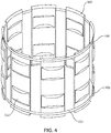
- FIG. 4 and FIG. 5 indicate that the tolerance ring 122 further includes a support structure 350 that is secured to the tolerance ring panels 300 in order to maintain the tolerance ring panels 300 position relative to each other.
- FIG. 4 shows that the support structure 350 includes a first ring 400 affixed to a top of each tolerance ring panel 300 and a second ring 402 affixed to a bottom of each tolerance ring panel 300.
- the rings 400, 402 include an inner periphery and the tolerance ring panels 300 can be affixed to the inner periphery of the rings 400, 402.
- the projections 322 on the tolerance ring panels 300 can extend radially inward and the tolerance ring panels 300 can be affixed to an outer periphery of the first and second rings 400, 402.
- tolerance ring panels 300 can be affixed to the inner periphery and the outer periphery of the rings 400, 402.
- the tolerance ring panels 300 can include a combination of panels having inwardly directed projections and panels having outwardly directed projections.
- each ring 400, 402 can include a gap 500 that can extend completely through the ring 400, 402 to form a split ring. Further, each ring 400, 402 can be deformable. In addition, each ring 400, 402 can be removably engaged with the tolerance ring panels 300 so that after installation of the tolerance ring panels 300 between and inner component and an outer component, the rings 400, 402 can be removed from the tolerance rings panels 300.
- each ring 400, 402 can have a cross-sectional diameter, D, and each arcuate panel has a thickness measured through the unformed portion, T.
- D can be ⁇ 50% T, such as 60% T, or 70% T.
- D can be ⁇ 300% T, such as ⁇ 250% T, ⁇ 200% T, ⁇ 150% T, or ⁇ 100% T.
- D can be within a range between and including any of the maximum and minimum values of D described herein.
- D can be ⁇ 50% T and ⁇ 300% T, such as ⁇ 50% T and ⁇ 250% T, ⁇ 50% T and ⁇ 200% T, ⁇ 50% T and ⁇ 150% T, or ⁇ 50% T and ⁇ 100% T.
- D can be ⁇ 60% T and ⁇ 300% T, such as ⁇ 60% T and ⁇ 250% T, ⁇ 60% T and ⁇ 200% T, ⁇ 60% T and ⁇ 150% T, or ⁇ 60% T and ⁇ 100% T.
- D can be ⁇ 70% T and ⁇ 300% T, such as ⁇ 70% T and ⁇ 250% T, ⁇ 70% T and ⁇ 200% T, ⁇ 70% T and ⁇ 150% T, or ⁇ 70% T and ⁇ 100% T.
- the support structure 350 can include a hollow, thin-walled cylinder 600.
- the cylinder 600 can be continuous or the cylinder 600 can include a slot, or gap 602, formed therein so that the cylinder 600 is completely split along the height of the cylinder 600.
- the cylinder 600 can include an outer surface 604.
- the tolerance ring panels 300, having outwardly directed projections 322, can be affixed to the outer surface 602 of the cylinder.
- the cylinder 600 can include an inner surface 606 and the tolerance ring panels 300, having inwardly directed projections can be affixed to the inner surface 604 of the cylinder.
- the cylinder 600 can include a film, a metallized film, or a foil. Moreover, the cylinder 600 can be soluble, e.g., in water, acetone, or some other appropriate solvent. Accordingly, after the tolerance ring 300 is installed between and an inner component and an outer component, the assembly can be immersed or bathed in the solvent to remove the cylinder.
- the cylinder 600 can be elastic or flexible. In such a case, the cylinder 600 can expand to fit around shafts having varying sizes within a range of tolerances. At least a portion of the inner surface 606 or the outer surface 604 of the cylinder 600 can be coated with an adhesive and the tolerance ring panels 300 can be fixed to the cylinder 600 via the adhesive.
- the adhesive can be soluble so that the cylinder can be removed from the tolerance ring 300 after installation.
- the cylinder 600 can include a sidewall thickness, T C , and each arcuate panel can have a thickness, T, measured through the unformed portion 320 of the tolerance ring panel.
- T C can be ⁇ 100% T, such as ⁇ 75% T, ⁇ 50% T, or ⁇ 25% T.
- T C can be ⁇ 1% T, such as ⁇ 2.5% T, or ⁇ 5% T.
- T C can be within a range between and including any of the values of T C described herein.
- T C can be ⁇ 100% T and ⁇ 1% T, such as ⁇ 100% T and ⁇ 2.5% T, or ⁇ 100% T and ⁇ 5% T.
- T C can be ⁇ 75% T and ⁇ 1% T, such as ⁇ 75% T and ⁇ 2.5% T, or ⁇ 75% T and ⁇ 5% T.
- T C can be ⁇ 50% T and ⁇ 1% T, such as ⁇ 50% T and ⁇ 2.5% T, or ⁇ 50% T and ⁇ 5% T.
- T C can be ⁇ 25% T and ⁇ 1% T, such as ⁇ 25% T and ⁇ 2.5% T, or ⁇ 25% T and ⁇ 5% T.
- the support structure 350 can include a plurality of discrete support structures 700.
- Each discrete support structure 700 can be connected to two adjacent tolerance ring panels 300.
- each discrete support structure 700 can be attached to the adjacent tolerance ring panels 300 along an edge of each tolerance ring panel 300.
- each discrete support structure 700 can slightly overlap the edges of each adjacent tolerance ring panel 300, e.g., over the outer surfaces of the tolerance ring panels 300 or the inner surfaces of the tolerance ring panels 300.
- each discrete support structure 700 can include a portion of a hollow, thin-walled cylinder. Further, each discrete support structure 700 can include a film, a metallized film, or a foil. Moreover, each discrete support structure 700 can be elastic or flexible. In a particular aspect, as illustrated in FIG. 7 , each adjacent pair of tolerance ring panels 300 can be connected to a discrete support structure 700. However, as depicted in FIG. 8 , one discrete support structure 700 may be removed from the assembly, to establish a gap 800 between two adjacent tolerance ring panels 300.
- each discrete support structure 700 can include a portion of a ring. Moreover, in still another aspect, each discrete support structure 700 can have a thickness that is greater than a wall thickness of the unformed portion 320 of the tolerance ring panel 300. In this aspect, each discrete support structure 700 can include an axial slot formed along a length of each edge of the discrete support structure 700 and an edge of each adjacent tolerance ring panel 300 can fit into a respective slot formed in the discrete support structure 700.
- each support structure 350 can include a height, H SS .
- each tolerance ring panel 300 can include a height, H P .
- H SS can be ⁇ H P.
- H SS can be ⁇ 95% H P , such as ⁇ 75% H P , ⁇ 50% H P , or ⁇ 25% H P.
- H SS can also be ⁇ 1% H P , such as ⁇ 5% H P , or ⁇ 10% H P.
- H SS can be within a range between and including any of the maximum or minimum values of H SS .
- H SS can be ⁇ 95% H P and ⁇ 1% H P , such as ⁇ 95% H P and ⁇ 5% H P , or ⁇ 95% H P and ⁇ 10% H P.
- H SS can be ⁇ 75% H P and ⁇ 1% H P , such as ⁇ 75% H P and ⁇ 5% H P , or ⁇ 75% H P and ⁇ 10% H P .
- H SS can be ⁇ 50% H P and ⁇ 1% H P , such as ⁇ 50% H P and ⁇ 5% H P , or ⁇ 50% H P and ⁇ 10% H P .
- H SS can be ⁇ 25% H P and ⁇ 1% H P , such as ⁇ 25% H P and ⁇ 5% H P , or ⁇ 25% H P and ⁇ 10% H P .
- H SS can be ⁇ H P so that a portion of the support structure 350 extends beyond a top of the tolerance ring panels 300.
- H SS can be ⁇ 105% H P , such as ⁇ 110% H P , or ⁇ 120% H P .
- H SS can be ⁇ 200% H P , such as ⁇ 175% H P , or ⁇ 150% H P .
- H SS can be within a range between and including any of the maximum and minimum values described herein.
- H SS can be ⁇ 105% H P and ⁇ 200% H P , such as ⁇ 105% H P and ⁇ 175% H P , or ⁇ 105% H P and ⁇ 150% H P .
- H SS can be ⁇ 110% H P and ⁇ 200% H P , such as ⁇ 110% H P and ⁇ 175% H P , or ⁇ 110% H P and ⁇ 150% H P .
- H SS can be ⁇ 120% H P and ⁇ 200% H P , such as ⁇ 120% H P and ⁇ 175% H P , or ⁇ 120% H P and ⁇ 150% H P .
- the support structure 350 can be shorter than the tolerance ring panels 300 but installed in such a manner that a portion of the support structure 350 extends beyond a top or a bottom of the tolerance ring panels 300.
- the pivot 120 and the bore 116 can include a central axis that lies along, or nearly along, the central axis 314 of the tolerance ring 122.
- the tolerance ring 122 can provide an axial stiffness that can substantially resist rocking movement of the pivot 120 relative to the bore 116 and the actuator 102 in which the central axis of the pivot 120 rotates about an axis perpendicular to the central axis (a longitudinal axis) with respect to the central axis 314.
- the axial stiffness of the tolerance ring 122 does not vary too greatly when measured at various locations circumferentially around an assembly that includes the tolerance ring 122.
- the axial stiffness, AS G of the tolerance ring 122 through the gap 312 can be measured in a first direction that passes through the gap 312 and a center 314 of the tolerance ring 122.
- the axial stiffness of the tolerance ring 122 perpendicular to the gap 312, AS PG can be measured in a second direction perpendicular to the first direction.
- AS G can be ⁇ 90% AS PG , such as ⁇ 91% AS PG , ⁇ 92% AS PG , ⁇ 93% AS PG , ⁇ 94% AS PG , or ⁇ 95% AS PG . Further, A SG can be ⁇ 100% AS PG , ⁇ 99% AS PG , ⁇ 98% AS PG , ⁇ 97% AS PG , or ⁇ 96% AS PG . Moreover, AS G can be within a range between, and including, any of the percentage values of AS PG disclosed above.
- the resonant frequency of the tolerance ring 122 does not vary greatly when measured at various locations circumferentially the assembly in which the tolerance ring 122 is installed.
- the resonant frequency of the tolerance ring 122 through the gap 312, RF G can be measured in a first direction that passes through the gap 312 and the center 314 of the tolerance ring 122.
- the resonant frequency of the tolerance ring 122 perpendicular to the gap 312, RF PG can be measured in a second direction perpendicular to the first direction.
- RF G can be ⁇ 90% RF PG , such as ⁇ 91% RF PG , ⁇ 92% RF PG , ⁇ 93% RF PG , ⁇ 94% RF PG , or ⁇ 95% RF PG . Further, RF G can be ⁇ 100% RF PG , ⁇ 99% RF PG , ⁇ 98% RF PG , ⁇ 97% RF PG , or ⁇ 96% RF PG . Moreover, RF G can be within a range between, and including, any of the percentage values of RF PG disclosed above.
- the tolerance ring 122 can include one wave bank 330, and one unformed section 320.
- the tolerance ring 122 can include two wave banks and two unformed sections, three wave banks and three unformed sections, four wave banks and four undeformed sections, five wave banks and five unformed sections, six wave banks and six unformed sections, etc.
- each wave bank includes three wave structures, in other aspects each wave bank can include one wave structure, two wave structures, four wave structures, five wave structures, six wave structures, etc.
- the tolerance ring e.g. any of the tolerance rings disclosed herein, can provide a concentricity, C, that is measured as a distance between a center of an inner component and a center of an outer component after assembly as described herein.
- C can be ⁇ 50 ⁇ m, such as ⁇ 45 ⁇ m, ⁇ 40 ⁇ m, ⁇ 35 ⁇ m, ⁇ 30 ⁇ m, ⁇ 25 ⁇ m, or ⁇ 20 ⁇ m.
- C can be ⁇ 1 ⁇ m, such as C ⁇ 5 ⁇ m.
- C can be within a range between, and including, any of the values of C described herein.
- a tolerance ring can be made from a metal, a metal alloy, or a combination thereof.
- the metal can include a ferrous metal.
- the metal can include steel.
- the steel can include stainless steel, such as austenitic stainless steel.
- the steel can include stainless steel comprising chrome, nickel, or a combination thereof.
- the steel can X10CrNi18-8 stainless steel.
- the tolerance ring can include a Vickers pyramid number hardness, VPN, which can be ⁇ 350, such as ⁇ 375, ⁇ 400, or ⁇ 425.
- VPN can also be ⁇ 500, such as ⁇ 475, or ⁇ 450.
- VPN can also be within a range between, and including, any of the VPN values described herein.
- VPN can be ⁇ 350 and ⁇ 500, such as ⁇ 350 and ⁇ 475, or ⁇ 350 and ⁇ 450.
- VPN can be ⁇ 375 and ⁇ 500, such as ⁇ 375 and ⁇ 475, or ⁇ 375 and ⁇ 450.
- VPN can be ⁇ 400 and ⁇ 500, such as ⁇ 400 and ⁇ 475, or ⁇ 400 and ⁇ 450.
- VPN can be ⁇ 425 and ⁇ 500, such as ⁇ 425 and ⁇ 475, or ⁇ 425 and ⁇ 450.
- the tolerance ring can be treated to increase its corrosion resistance.
- the tolerance ring can be passivated.
- the tolerance ring can be passivated according to the ASTM standard A967.
- the stock material from which the tolerance ring can be formed can have a thickness, t, and t can be ⁇ 0.075 mm, such as ⁇ 0.080 mm, ⁇ 0.085 mm, ⁇ 0.087 mm, ⁇ 0.090 mm, ⁇ 0.095 mm, or ⁇ 0.100 mm.
- t can be ⁇ 0.115 mm, such as ⁇ 0.113 mm, ⁇ 0.110 mm, or ⁇ 0.105 mm.
- t can be within a range between, and including, any of the values of t disclosed above.
- t can be ⁇ 0.075 mm and ⁇ 0.115 mm, such as ⁇ 0.075 mm and ⁇ 0.113 mm, ⁇ 0.075 mm and ⁇ 0.110 mm, or ⁇ 0.075 mm and ⁇ 0.105 mm.
- t can be ⁇ 0.080 mm and ⁇ 0.115 mm, such as ⁇ 0.080 mm and ⁇ 0.113 mm, ⁇ 0.080 mm and ⁇ 0.110 mm, or ⁇ 0.080 mm and ⁇ 0.105 mm.
- t can be ⁇ 0.085 mm and ⁇ 0.115 mm, such as ⁇ 0.085 mm and ⁇ 0.113 mm, ⁇ 0.085 mm and ⁇ 0.110 mm, or ⁇ 0.085 mm and ⁇ 0.105 mm.
- t can be ⁇ 0.087 mm and ⁇ 0.115 mm, such as ⁇ 0.087 mm and ⁇ 0.113 mm, ⁇ 0.087 mm and ⁇ 0.110 mm, or ⁇ 0.087 mm and ⁇ 0.105 mm.
- t can be ⁇ 0.090 mm and ⁇ 0.115 mm, such as ⁇ 0.090 mm and ⁇ 0.113 mm, ⁇ 0.090 mm and ⁇ 0.110 mm, or ⁇ 0.090 mm and ⁇ 0.105 mm. Even further, t can be ⁇ 0.095 mm and ⁇ 0.115 mm, such as ⁇ 0.095 mm and ⁇ 0.113 mm, ⁇ 0.095 mm and ⁇ 0.110 mm, or ⁇ 0.095 mm and ⁇ 0.105 mm.
- t can be ⁇ 0.1 mm and ⁇ 0.115 mm, such as ⁇ 0.1 mm and ⁇ 0.113 mm, ⁇ 0.1 mm and ⁇ 0.110 mm, or ⁇ 0.1 mm and ⁇ 0.105 mm.
- the tolerance ring may have an overall outer diameter, OD, and OD can be ⁇ 5 mm, such as ⁇ 6 mm, ⁇ 7 mm, ⁇ 8 mm, or ⁇ 9 mm.
- the OD can be ⁇ 20 mm, such as ⁇ 15 mm, ⁇ 14 mm, ⁇ 13 mm, ⁇ 12 mm, or ⁇ 10 mm. Further, OD can be within a range between and including any of the values of OD described herein.
- OD can be ⁇ 5 mm and ⁇ 20 mm, such as ⁇ 5 mm and ⁇ 15 mm, ⁇ 5 mm and ⁇ 14 mm, ⁇ 5 mm and ⁇ 13 mm, ⁇ 5 mm and ⁇ 12 mm, or ⁇ 5 mm and ⁇ 10 mm.
- OD can be ⁇ 6 mm and ⁇ 20 mm, such as ⁇ 6 mm and ⁇ 15 mm, ⁇ 6 mm and ⁇ 14 mm, ⁇ 6 mm and ⁇ 13 mm, ⁇ 6mm and ⁇ 12 mm, or ⁇ 6 mm and ⁇ 10 mm.
- OD can also be ⁇ 7 mm and ⁇ 20 mm, such as ⁇ 7 mm and ⁇ 15 mm, ⁇ 7 mm and ⁇ 14 mm, ⁇ 7 mm and ⁇ 13 mm, ⁇ 7 mm and ⁇ 12 mm, or ⁇ 7 mm and ⁇ 10 mm.
- OD can be ⁇ 8 mm and ⁇ 20 mm, such as ⁇ 8 mm and ⁇ 15 mm, ⁇ 8 mm and ⁇ 14 mm, ⁇ 8 mm and ⁇ 13 mm, ⁇ 8 mm and ⁇ 12 mm, or ⁇ 8 mm and ⁇ 10 mm.
- OD can be ⁇ 9 mm and ⁇ 20 mm, such as ⁇ 9 mm and ⁇ 15 mm, ⁇ 9 mm and ⁇ 14 mm, ⁇ 9 mm and ⁇ 13 mm, ⁇ 9 mm and ⁇ 12 mm, or ⁇ 9 mm and ⁇ 10 mm.
- the tolerance ring can have an overall length, L, and L can be ⁇ 20 mm, such as ⁇ 17 mm, ⁇ 15 mm, ⁇ 14 mm, or ⁇ 13 mm.
- L can be ⁇ 5 mm, such as ⁇ 6 mm, ⁇ 7 mm, ⁇ 8 mm, ⁇ 9 mm, or ⁇ 10 mm.
- L can be within a range between, and including, any of the values of L described above.
- L can be ⁇ 20 mm and ⁇ 5 mm, such as ⁇ 20 mm and ⁇ 6 mm, ⁇ 20 mm and ⁇ 7 mm, ⁇ 20 mm and ⁇ 8 mm, ⁇ 20 mm and ⁇ 9 mm, or ⁇ 20 mm and ⁇ 10 mm.
- L can be ⁇ 17 mm and ⁇ 5 mm, such as ⁇ 17 mm and ⁇ 6 mm, ⁇ 17 mm and ⁇ 7 mm, ⁇ 17 mm and ⁇ 8 mm, ⁇ 17 mm and ⁇ 9 mm, or ⁇ 17 mm and ⁇ 10 mm.
- L can be ⁇ 15 mm and ⁇ 5 mm, such as ⁇ 15 mm and ⁇ 6 mm, ⁇ 15 mm and ⁇ 7 mm, ⁇ 15 mm and ⁇ 8 mm, ⁇ 15 mm and ⁇ 9 mm, or ⁇ 15 mm and ⁇ 10 mm.
- L can be ⁇ 14 mm and ⁇ 5 mm, such as ⁇ 14 mm and ⁇ 6 mm, ⁇ 14 mm and ⁇ 7 mm, ⁇ 14 mm and ⁇ 8 mm, ⁇ 14 mm and ⁇ 9 mm, or ⁇ 14 mm and ⁇ 10 mm.
- L can be ⁇ 13 mm and ⁇ 5 mm, such as ⁇ 13 mm and ⁇ 6 mm, ⁇ 13 mm and ⁇ 7 mm, ⁇ 13 mm and ⁇ 8 mm, ⁇ 13 mm and ⁇ 9 mm, or ⁇ 13 mm and ⁇ 10 mm.
- the resulting tolerance ring panels are substantially free of any burrs. Specifically, no burrs are visible along any of the cut edges under a visual inspection of the tolerance ring under 10x magnification.
- a tolerance ring is manufactured from X10CrNi18-8 stainless steel stock.
- the stainless steel stock has a thickness of 0.1 mm ⁇ 0.013. Further, the stainless steel stock has a VPN of 400-450 and is passivated to ASTM A967.
- the formed tolerance ring includes eight tolerance ring panels having two projections extending radially outward formed in each tolerance ring panel. The tolerance ring panels are equally spaced around the tolerance ring. Moreover, the projections are vertically aligned.
- the tolerance ring is installed around a post and this assembly is installed within a ring.
- This assembly is suspended using fishing line and two lasers are placed perpendicular to a flat face of the ring on the same side of the ring.
- the lasers are placed 180 degrees from each other.
- One laser is used as a reference laser and the other laser is used as a measurement laser.
- the ring is tapped under the measurement laser using a hammer that has a force transducer incorporated therein.
- the lasers and the force transducer of the hammer are coupled to a microprocessor and provide inputs to the microprocessor.
- the microprocessor includes software that calculates resonant frequencies from the inputs provided by the hammer and the lasers.
- the resonant frequency is directly related to the axial stiffness of the tolerance ring.
- the resonant frequency measured along an axis that bisects two opposite gaps and passes through a center of the assembly is nearly equal to the resonant frequency measured along an axis perpendicular to the first axis through a second pair of opposite gaps.
- the axial stiffness through the first pair of opposite gaps is essentially the same as the axial stiffness through the second pair of opposite gaps perpendicular to the first pair.
- the tolerance ring described herein provides a tolerance ring panel arrangement having very little, if any, panel-to-panel force interaction. These discrete panels are essentially isolated from each other and can provide a resonant frequency and stiffness that do not substantially vary circumferentially around the tolerance ring. As such, the tolerance ring can maintain the post in alignment within the bore and can substantially prevent any rocking of the post within the bore under normal operational loads in nearly any radial direction.
Landscapes
- Engineering & Computer Science (AREA)
- General Engineering & Computer Science (AREA)
- Mechanical Engineering (AREA)
- Moving Of Heads (AREA)
- Support Of The Bearing (AREA)
- Mounting Of Bearings Or Others (AREA)
- Rolling Contact Bearings (AREA)
- Connection Of Plates (AREA)
Description
- The present invention is directed generally to tolerance rings, and particularly to tolerance rings for actuator arms within hard disk drives.
- The present invention relates to tolerance ring assemblies, wherein a tolerance ring provides an interference fit between parts of an assembly, in which a first part has a cylindrical portion located in a cylindrical bore of a second part. In particular, the present disclosure relates to assemblies having a tolerance ring that provides an interference fit between a cylindrical component such as a shaft or a bearing and a housing for the shaft.
- Improved engineering techniques have resulted in the need for greater accuracy of machine parts, raising manufacturing costs. Very close tolerances are required where press fits, splines, pins or keyways are employed to transmit torque in applications such as pulleys, flywheels or driveshafts.
- Tolerance rings may be used to provide an interference fit between parts required to transmit torque. Tolerance rings provide a low cost means of providing an interference fit between parts that may not be machined to exact dimensions. Tolerance rings have a number of other potential advantages, such as compensating for different linear coefficients of expansion between the parts, allowing rapid apparatus assembly, and durability.
- A tolerance ring generally comprises a strip of resilient material, for example a metal such as spring steel, the ends of which are brought together to form a ring. A band of protrusions extend radially outwards from the ring, or radially inwards towards the center of the ring. Usually, the protrusions are formations, possibly regular formations, such as corrugations, ridges or waves.
- When the ring is located in the annular space between, for example, a shaft and a bore in a housing in which the shaft is located, the protrusions are compressed. Each protrusion acts as a spring and exerts a radial force against the shaft and the surface of the bore, providing an interference fit between the shaft and the housing. Rotation of the housing or the shaft will produce similar rotation in the other of the shaft or the housing, as torque is transmitted by the tolerance ring. Typically, the band of protrusions is axially flanked by annular regions of the ring that have no formations (known in the art as "unformed regions" of the tolerance ring).
- Although tolerance rings usually comprise a strip of resilient material that is curved to allow the easy formation of a ring by overlapping the ends of the strip, a tolerance ring may also be manufactured as an annular band. The term "tolerance ring" as used hereafter includes both types of tolerance ring. The term "shaft" as used hereafter includes any assembly component with a cylindrical portion, such as a shaft or a bearing.
US 4 569 614 A refers to a coupling for fastening two members whose opposed faces keep an equal gap and are free to relatively displace to the left or right, wherein a wedge inclining with an angle narrower than the friction angle to osculate each of the opposing face of the members, is capable of wedging the opposing faces by relative displacement of the members toward the rising side of the wedge. The coupling is arranged on the left and right respectively in the direction of relative displacement of the members, so that two members can be coupled plainly, rigidly and free from lowering of the axis strength, permitting an easy phase adjustment or dividing or the like.EP 1 759 955 A2 refers to a bush for insertion between two relatively moveable inter-engaging inner and outer members, the bush having a portion which is arranged to accommodate expansion and/or contraction between the members under varying temperature load. The portion may be corrugated, for example and/or have a thickness in section which is less than other parts of the bush. The members may be inner and outer steering column members for a vehicle.DE 10 2011 015 199 A1 refers to a device having an azimuth transmission, and an azimuth drive comprising an output i.e. shaft, that is connected with the transmission, where the drive is designed as a frequency-controlled electric motor. A torque limiter is arranged between the drive and the transmission in an inner groove of a plug-in sleeve and provided for limiting torque acting on the drive. The torque limiter is designed as a casing and connected to an insertion part that is connected with the output of the drive or the transmission in a torque-proof manner.US 6 480 363 B1 relates to an improved pivot assembly for a hard disk drive actuator. - Accordingly, the industry continues to need improvements in tolerance rings, particularly tolerance rings installed within hard disk drives.
- The present invention can be better understood, and its numerous features and advantages made apparent to those skilled in the art by referencing the accompanying drawings.
-
FIG. 1 includes an exploded perspective view of a hard disk drive assembly in accordance with an embodiment. -
FIG. 2 includes a cross-sectional view of a hard disk drive assembly in accordance with an embodiment. -
FIG. 3 includes a perspective view of a tolerance ring in accordance with an embodiment. -
FIG. 4 includes a perspective view of a tolerance ring in accordance with another embodiment. -
FIG. 5 includes a perspective view of a tolerance ring in accordance with yet another embodiment. -
FIG. 6 includes a perspective view of a tolerance ring as an example not part of the present invention. -
FIG. 7 includes a perspective view of a tolerance ring as an example not part of the present invention. -
FIG. 8 includes a perspective view of a tolerance ring as an example not part of the present invention. - The use of the same reference symbols in different drawings indicates similar or identical items.
- The following description is directed to tolerance rings, and particularly, to tolerance rings that can be installed within a hard disk drive between a pivot assembly and a bore formed in an actuator arm. In one aspect, a tolerance ring can be fitted around the pivot assembly and then this assembly can be inserted into the bore. Alternatively, the tolerance ring can be inserted into the bore and the pivot can be inserted into the tolerance ring.
- In a typical tolerance ring, the waves nearest to the gap tend to be the weakest, i.e., least stiff, since the waves have a gap on one side and material on the other and the remaining waves in the tolerance ring are flanked by material on both sides. This variation in stiffness can cause performance variables, e.g., resonance and alignment, to be very dependent on a position of the gap in the hard disk drive assembly. Attempting to optimize the gap location for one performance parameter can adversely affect other performance parameters. This, in turn, can compromise overall performance.
- A tolerance ring according to one or more of the embodiments described herein is defined in claim 1. It includes a plurality discrete tolerance ring panels that can be equally spaced around the circumference of the tolerance ring and the tolerance ring can be symmetric about an axis passing through the center of the tolerance ring and a gap in the tolerance ring.
- The arrangement provided by the tolerance ring panels disclosed herein can provide a tolerance ring having a resonant frequency and stiffness that do not substantially vary circumferentially around the tolerance ring. As such, the tolerance ring can maintain the pivot assembly in alignment within the bore and can substantially prevent any rocking of the post within the bore under normal operational loads in nearly any radial direction.
- Referring initially to
FIG. 1 , a hard disk drive assembly is shown and is generally designated 100. The harddisk drive assembly 100 can include anactuator arm 102 for a hard disk drive and apivot assembly 104. - As illustrated, the
actuator arm 102 can include aproximal end 110 and adistal end 112. A plurality of read/writeheads 114 can extend from thedistal end 112 of theactuator arm 102. Moreover, theactuator arm 102 can be formed with abore 116 near theproximal end 110 of theactuator arm 102. -
FIG. 1 further indicates that thepivot assembly 104 can include apivot 120 and atolerance ring 122. Thepivot 120 can include aninner member 124 and anouter member 126, and theouter member 126 can rotate with respect to theinner member 124. - In a particular aspect, the
tolerance ring 122 can fit around thepivot 120 and then, thepivot assembly 104 can be installed within thebore 116. In another aspect, thetolerance ring 122 can be placed within thebore 116 and thepivot 120 can be inserted into thetolerance ring 122. Thetolerance ring 122 can establish an interference fit between theouter member 126 of thepivot 120 and thebore 116 of theactuator arm 102. As such, theactuator arm 102 can rotate with theouter member 126 of thepivot 120 around theinner member 124 of thepivot 120. - Accordingly, as shown in
FIG. 2 , thetolerance ring 122 can be installed within thebore 116 between an outer component, theactuator arm 102, and an inner component, thepivot 120. In a particular aspect, when installed, no portion of thetolerance ring 122 extends beyond the top or bottom of the bore and thetolerance ring 122 can be completely contained within thebore 116. In another aspect, a portion of thetolerance ring 122, e.g., a top, a bottom, a structure on a top, a structure on a bottom, or a combination thereof, can extend from the bore. - As illustrated in
FIG. 2 , and described in greater detail below, thetolerance ring 122 can be configured to engage the inner wall of thebore 116 and the outer wall of thepivot 120 in order to maintain thepivot 120 within theactuator arm 102 in an interference fit. Thetolerance ring 122 can account for dimensional variations by expanding around thepivot 120 as it is installed thereon and then, at least partially deforming, or compressing, within thebore 116 during installation. - Referring now to
FIG. 3 , details concerning thetolerance ring 122 are illustrated. As stated above, thetolerance ring 122 is configured to be deployed in an interference fit between an inner component and an outer component to provide torque coupling between an inner component and an outer component. The inner component can be the pivot assembly, described above, and the outer component can be the actuator arm for the hard disk drive assembly, also described above. - As depicted, the
tolerance ring 122 can include a plurality of discretetolerance ring panels 300. Eachtolerance ring panel 300 can include anarcuate sidewall 302 having a top 304 and a bottom 306. InFIG. 3 , thearcuate sidewall 302 of eachtolerance ring panel 300 can also include anupper flange portion 308 that can extend from the top 304 of thearcuate sidewall 302 and alower flange portion 310 that can extend from thebottom 306 of thearcuate sidewall 302. - In a particular aspect, the
tolerance ring panels 300 are spaced apart circumferentially to form a plurality ofgaps 312 within thetolerance ring 122. Eachgap 312 can include a circumferential width, WG, and WG is uniform around thetolerance ring 122. Alternatively, WG can vary around thetolerance ring 122. In another aspect, eachtolerance ring panel 300 can have a circumferential width, WP. WP can be uniform around the tolerance ring. In another aspect, WP can vary around the tolerance ring. - In another aspect, WG can be ≤ 400% WP, such as ≤ 300% WP, ≤ 200% WP, ≤ 100% WP, or ≤ 50% WP. Further, WG can be ≥ 1% WP, such as ≥ 5% WP, or ≥ 10% WP. In another aspect, WG can be within a range between and including any of the values of WG described herein. For example, WG can be ≤ 400% WP and ≥ 1% WP, such as ≤ 400% WP and ≥ 5% WP, ≤ 400% WP and or ≥ 10% WP. WG can be ≤ 300% WP and ≥ 1% WP, such as ≤ 300% WP and ≥ 5% WP, ≤ 300% WP and or ≥ 10% WP. Further, WG can be ≤ 200% WP and ≥ 1% WP, such as ≤ 200% WP and ≥ 5% WP, ≤ 200% WP and or ≥ 10% WP. Still further, WG can be ≤ 150% WP and ≥ 1% WP, such as ≤ 150% WP and ≥ 5% Wp, ≤ 150% Wp and or ≥ 10% Wp. Even further, WG can be ≤ 100% Wp and ≥ 1% Wp, such as ≤ 100% WP and ≥ 5% WP, ≤ 100% WP and or ≥ 10% WP.
- In a particular embodiment, the
tolerance ring 122 can include at least two discretetolerance ring panels 300, such as at least three discretetolerance ring panels 300, at least four discretetolerance ring panels 300, at least five discretetolerance ring panels 300, at least six discretetolerance ring panels 300, or at least eight discretetolerance ring panels 300. Moreover, thetolerance ring 122 may include no more than twenty discretetolerance ring panels 300. Further, thetolerance ring 122 may include between and including two and twenty discretetolerance ring panels 300, such as between and including three and twenty discretetolerance ring panels 300, between and including four and twenty discretetolerance ring panels 300, between and including five and twenty discretetolerance ring panels 300, between and including six and twenty discretetolerance ring panels 300, or between and including eight and twenty discretetolerance ring panels 300. - The
tolerance ring 122 can include acentral axis 314 and as shown inFIG. 2 andFIG. 3 , in a particular aspect, theflange portions central axis 314 of thetolerance ring 122. It is to be understood that theflange portions central axis 314. In either case, theflanges portions central axis 314. In a particular aspect, α can be ≥ 5°, such as ≥ 10°, or ≥ 15°. In another aspect, α can be ≤ 30°, such as ≤ 25°, or ≤ 20°. In another aspect, α can be within a range between, and including, any of the maximum and minimum values of α disclosed herein. - For example, α can be ≥ 5° and less than ≤ 30°, such as ≥ 5° and ≤ 25°, or ≥ 5° and ≤ 20°. Further, α can be ≥ 10° and less than ≤ 30°, such as ≥ 10° and ≤ 25°, or ≥ 10° and ≤ 20°. Even further, α can be ≥ 15° and less than ≤ 30°, such as ≥ 15° and ≤ 25°, or ≥ 15° and ≤ 20°.
- As more clearly illustrated in
FIG. 2 , thetolerance ring 122 may include an overall wall thickness, tOW, that is the distance between the inner surface of thearcuate sidewall 302 of thetolerance ring panel 300 and an outer surface of a wall structure formed in thesidewall 302 of thetolerance ring panel 300. Further, eachflange portion arcuate sidewall 302 such that eachflange portion arcuate sidewall 302 of the tolerance ring panel 30 and the outer edge of theflange portion - For example, tOF can be ≥ 30% tOW and ≤ 98% tOW, such as ≥ 30% tOW and ≤ 95% tOW, ≥ 30% tOW and ≤ 90% tOW, ≥ 30% tOW and ≤ 85% tOW, or ≥ 30% tOW and ≤ 80% tOW. Further, tOF can be ≥ 35% tOW and ≤ 98% tOW, such as ≥ 35% tOW and ≤ 95% tOW, ≥ 35% tOW and ≤ 90% tOW, ≥ 35% tOW and ≤ 85% tOW, or ≥ 35% tOW and ≤ 80% tOW. Moreover, tOF can be ≥ 40% tOW and ≤ 98% tOW, such as ≥ 40% tOW and ≤ 95% tOW, ≥ 40% tOW and ≤ 90% tOW, ≥ 40% tOW and ≤ 85% tOW, or ≥ 40% tOW and ≤ 80% tOW. Further still, tOF can be ≥ 45% tOW and ≤ 98% tOW, such as ≥ 45% tOW and ≤ 95% tOW, ≥ 45% tOW and ≤ 90% tOW, ≥ 45% tOW and ≤ 85% tOW, or ≥ 45% tOW and ≤ 80% tOW. Even further, tOF can be ≥ 50% tOW and ≤ 98% tOW, such as ≥ 50% tOW and ≤ 95% tOW, ≥ 50% tOW and ≤ 90% tOW, ≥ 50% tOW and ≤ 85% tOW, or ≥ 50% tOW and ≤ 80% tOW. In another aspect, tOF can be ≥ 55% tOW and ≤ 98% tOW, such as ≥ 55% tOW and ≤ 95% tOW, ≥ 55% tOW and ≤ 90% tOW, ≥ 55% tOW and ≤ 85% tOW, or ≥ 55% tOW and ≤ 80% tOW. In still another aspect, tOF can be ≥ 60% tOW and ≤ 98% tOW, such as ≥ 60% tOW and ≤ 95% tOW, ≥ 60% tOW and ≤ 90% tOW, ≥ 60% tOW and ≤ 85% tOW, or ≥ 60% tOW and ≤ 80% tOW.
- Returning to
FIG. 3 , thearcuate sidewall 302 can include anunformed portion 320. At least oneprojection 322 can be formed in thearcuate sidewall 302 and can extend from thearcuate sidewall 302. Each of the at least oneprojection 322 can be surrounded by theunformed portion 320 of thearcuate sidewall 302. The at least oneprojection 322 can extend radially inward, radially outward, or both radially inward and radially outward with respect to thecentral axis 314 of thetolerance ring 122. The at least oneprojection 322 can be adapted to contact an inner surface of an outer component or an outer surface of an inner component. - In certain embodiments that include
flange portions projections 322 that extend in an inward direction relative to thecentral axis 314, tOW can be measured between an outer surface of thearcuate sidewall 302 of thetolerance ring panel 302 and an inner surface of a wall structure formed in thearcuate sidewall 302 of thetolerance ring panel 302. Further, in such embodiments, tOF is measured between the outer surface of thearcuate sidewall 302 of thetolerance ring panel 302 and the inner edge of theflange portion - The at least one
projection 322 formed in eacharcuate sidewall 302 can include a single elongated wave structure or a wave column that includes two or more wave structures vertically aligned with each other along thearcuate sidewall 302 of thetolerance ring panel 300, along a length of thetolerance ring panel 300. - As illustrated in
FIG. 3 , the at least oneprojection 322 can include awave column 330 that can afirst wave 332 near the top 306 of thearcuate sidewall 302 of thetolerance ring panel 300 and asecond wave 334 near thebottom 308 of thearcuate sidewall 304 of thetolerance ring panel 300. In a particular aspect, thefirst wave 332 can be centered within the top half of the length of thetolerance ring panel 300. Moreover, thesecond wave 334 can be centered within the bottom half of the length of thetolerance ring panel 300. -
FIG. 4 andFIG. 5 indicate that thetolerance ring 122 further includes asupport structure 350 that is secured to thetolerance ring panels 300 in order to maintain thetolerance ring panels 300 position relative to each other.FIG. 4 shows that thesupport structure 350 includes a first ring 400 affixed to a top of eachtolerance ring panel 300 and asecond ring 402 affixed to a bottom of eachtolerance ring panel 300. Therings 400, 402 include an inner periphery and thetolerance ring panels 300 can be affixed to the inner periphery of therings 400, 402. In alternative embodiment, theprojections 322 on thetolerance ring panels 300 can extend radially inward and thetolerance ring panels 300 can be affixed to an outer periphery of the first andsecond rings 400, 402. In another aspect,tolerance ring panels 300 can be affixed to the inner periphery and the outer periphery of therings 400, 402. In such a case, thetolerance ring panels 300 can include a combination of panels having inwardly directed projections and panels having outwardly directed projections. - In a particular aspect, as illustrated in
FIG. 5 , eachring 400, 402 can include agap 500 that can extend completely through thering 400, 402 to form a split ring. Further, eachring 400, 402 can be deformable. In addition, eachring 400, 402 can be removably engaged with thetolerance ring panels 300 so that after installation of thetolerance ring panels 300 between and inner component and an outer component, therings 400, 402 can be removed from the tolerance ringspanels 300. - In another aspect, each
ring 400, 402 can have a cross-sectional diameter, D, and each arcuate panel has a thickness measured through the unformed portion, T. In this aspect, D can be ≥ 50% T, such as 60% T, or 70% T. Moreover, D can be ≤ 300% T, such as ≤ 250% T, ≤ 200% T, ≤ 150% T, or ≤ 100% T. In another aspect, D can be within a range between and including any of the maximum and minimum values of D described herein. - For example, D can be ≥ 50% T and ≤ 300% T, such as ≥ 50% T and ≤ 250% T, ≥ 50% T and ≤ 200% T, ≥ 50% T and ≤ 150% T, or ≥ 50% T and ≤ 100% T. D can be ≥ 60% T and ≤ 300% T, such as ≥ 60% T and ≤ 250% T, ≥ 60% T and ≤ 200% T, ≥ 60% T and ≤ 150% T, or ≥ 60% T and ≤ 100% T. Further, D can be ≥ 70% T and ≤ 300% T, such as ≥ 70% T and ≤ 250% T, ≥ 70% T and ≤ 200% T, ≥ 70% T and ≤ 150% T, or ≥ 70% T and ≤ 100% T.
- In an example, not part of the present invention, as illustrated in
FIG. 6 , thesupport structure 350 can include a hollow, thin-walled cylinder 600. Thecylinder 600 can be continuous or thecylinder 600 can include a slot, orgap 602, formed therein so that thecylinder 600 is completely split along the height of thecylinder 600. As indicated inFIG. 6 , thecylinder 600 can include anouter surface 604. Thetolerance ring panels 300, having outwardly directedprojections 322, can be affixed to theouter surface 602 of the cylinder. In another aspect, thecylinder 600 can include aninner surface 606 and thetolerance ring panels 300, having inwardly directed projections can be affixed to theinner surface 604 of the cylinder. - The
cylinder 600 can include a film, a metallized film, or a foil. Moreover, thecylinder 600 can be soluble, e.g., in water, acetone, or some other appropriate solvent. Accordingly, after thetolerance ring 300 is installed between and an inner component and an outer component, the assembly can be immersed or bathed in the solvent to remove the cylinder. In another aspect, thecylinder 600 can be elastic or flexible. In such a case, thecylinder 600 can expand to fit around shafts having varying sizes within a range of tolerances. At least a portion of theinner surface 606 or theouter surface 604 of thecylinder 600 can be coated with an adhesive and thetolerance ring panels 300 can be fixed to thecylinder 600 via the adhesive. In another aspect, the adhesive can be soluble so that the cylinder can be removed from thetolerance ring 300 after installation. - In a particular aspect, the
cylinder 600 can include a sidewall thickness, TC, and each arcuate panel can have a thickness, T, measured through theunformed portion 320 of the tolerance ring panel. In this aspect, TC can be ≤ 100% T, such as ≤ 75% T, ≤ 50% T, or ≤ 25% T. TC can be ≥ 1% T, such as ≥ 2.5% T, or ≥ 5% T. Moreover, TC can be within a range between and including any of the values of TC described herein. - For example, TC can be ≤ 100% T and ≥ 1% T, such as ≤ 100% T and ≥ 2.5% T, or ≤ 100% T and ≥ 5% T. Further, TC can be ≤ 75% T and ≥ 1% T, such as ≤ 75% T and ≥ 2.5% T, or ≤ 75% T and ≥ 5% T. Still further, TC can be ≤ 50% T and ≥ 1% T, such as ≤ 50% T and ≥ 2.5% T, or ≤ 50% T and ≥ 5% T. Even further, TC can be ≤ 25% T and ≥ 1% T, such as ≤ 25% T and ≥ 2.5% T, or ≤ 25% T and ≥ 5% T.
- Referring to
FIG. 7 andFIG. 8 , which show examples not part of the present invention, thesupport structure 350 can include a plurality ofdiscrete support structures 700. Eachdiscrete support structure 700 can be connected to two adjacenttolerance ring panels 300. In particular, eachdiscrete support structure 700 can be attached to the adjacenttolerance ring panels 300 along an edge of eachtolerance ring panel 300. Further, eachdiscrete support structure 700 can slightly overlap the edges of each adjacenttolerance ring panel 300, e.g., over the outer surfaces of thetolerance ring panels 300 or the inner surfaces of thetolerance ring panels 300. - In a particular aspect, as illustrated in
FIG. 7 andFIG. 8 , eachdiscrete support structure 700 can include a portion of a hollow, thin-walled cylinder. Further, eachdiscrete support structure 700 can include a film, a metallized film, or a foil. Moreover, eachdiscrete support structure 700 can be elastic or flexible. In a particular aspect, as illustrated inFIG. 7 , each adjacent pair oftolerance ring panels 300 can be connected to adiscrete support structure 700. However, as depicted inFIG. 8 , onediscrete support structure 700 may be removed from the assembly, to establish agap 800 between two adjacenttolerance ring panels 300. - In another aspect, each
discrete support structure 700 can include a portion of a ring. Moreover, in still another aspect, eachdiscrete support structure 700 can have a thickness that is greater than a wall thickness of theunformed portion 320 of thetolerance ring panel 300. In this aspect, eachdiscrete support structure 700 can include an axial slot formed along a length of each edge of thediscrete support structure 700 and an edge of each adjacenttolerance ring panel 300 can fit into a respective slot formed in thediscrete support structure 700. - In each of the various aspects described herein, each
support structure 350 can include a height, HSS. Moreover, eachtolerance ring panel 300 can include a height, HP. In one aspect, HSS can be ≤ HP. For example, HSS can be ≤ 95% HP, such as ≤ 75% HP, ≤ 50% HP, or ≤ 25% HP. HSS can also be ≥ 1% HP, such as ≥ 5% HP, or ≥ 10% HP. In this aspect, HSS can be within a range between and including any of the maximum or minimum values of HSS. - For example, HSS can be ≤ 95% HP and ≥ 1% HP, such as ≤ 95% HP and ≥ 5% HP, or ≤ 95% HP and ≥ 10% HP. Further, HSS can be ≤ 75% HP and ≥ 1% HP, such as ≤ 75% HP and ≥ 5% HP, or ≤ 75% HP and ≥ 10% HP. Even further, HSS can be ≤ 50% HP and ≥ 1% HP, such as ≤ 50% HP and ≥ 5% HP, or ≤ 50% HP and ≥ 10% HP. Further still, HSS can be ≤ 25% HP and ≥ 1% HP, such as ≤ 25% HP and ≥ 5% HP, or ≤ 25% HP and ≥ 10% HP.
- In another aspect, to facilitate removal of the
support structure 350, HSS can be ≥ HP so that a portion of thesupport structure 350 extends beyond a top of thetolerance ring panels 300. For example, HSS can be ≥ 105% HP, such as ≥ 110% HP, or ≥ 120% HP. In this aspect, HSS can be ≤ 200% HP, such as ≤ 175% HP, or ≤ 150% HP. HSS can be within a range between and including any of the maximum and minimum values described herein. - For example, HSS can be ≥ 105% HP and ≤ 200% HP, such as ≥ 105% HP and ≤ 175% HP, or ≥ 105% HP and ≤ 150% HP. Moreover, HSS can be ≥ 110% HP and ≤ 200% HP, such as ≥ 110% HP and ≤ 175% HP, or ≥ 110% HP and ≤ 150% HP. Also, HSS can be ≥ 120% HP and ≤ 200% HP, such as ≥ 120% HP and ≤ 175% HP, or ≥ 120% HP and ≤ 150% HP.
- In yet another aspect, the
support structure 350 can be shorter than thetolerance ring panels 300 but installed in such a manner that a portion of thesupport structure 350 extends beyond a top or a bottom of thetolerance ring panels 300. - In a particular aspect, when the
pivot assembly 104 is installed within thebore 116 of the actuator arm with thetolerance ring 122 disposed there between, thepivot 120 and thebore 116 can include a central axis that lies along, or nearly along, thecentral axis 314 of thetolerance ring 122. Thetolerance ring 122 can provide an axial stiffness that can substantially resist rocking movement of thepivot 120 relative to thebore 116 and theactuator 102 in which the central axis of thepivot 120 rotates about an axis perpendicular to the central axis (a longitudinal axis) with respect to thecentral axis 314. - When left unconstrained, such rocking motion can cause the read/write heads 114 to contact a hard disk. This contact is undesired and can cause failure of a hard disk drive. In a particular aspect, the axial stiffness of the
tolerance ring 122 does not vary too greatly when measured at various locations circumferentially around an assembly that includes thetolerance ring 122. For example, the axial stiffness, ASG, of thetolerance ring 122 through thegap 312 can be measured in a first direction that passes through thegap 312 and acenter 314 of thetolerance ring 122. The axial stiffness of thetolerance ring 122 perpendicular to thegap 312, ASPG, can be measured in a second direction perpendicular to the first direction. ASG can be ≥ 90% ASPG, such as ≥ 91% ASPG, ≥ 92% ASPG, ≥ 93% ASPG, ≥ 94% ASPG, or ≥ 95% ASPG. Further, ASG can be ≤ 100% ASPG, ≤ 99% ASPG, ≤ 98% ASPG, ≤ 97% ASPG, or ≤ 96% ASPG. Moreover, ASG can be within a range between, and including, any of the percentage values of ASPG disclosed above. - Additionally, the resonant frequency of the
tolerance ring 122 does not vary greatly when measured at various locations circumferentially the assembly in which thetolerance ring 122 is installed. For example, the resonant frequency of thetolerance ring 122 through thegap 312, RFG, can be measured in a first direction that passes through thegap 312 and thecenter 314 of thetolerance ring 122. The resonant frequency of thetolerance ring 122 perpendicular to thegap 312, RFPG, can be measured in a second direction perpendicular to the first direction. RFG can be ≥ 90% RFPG, such as ≥ 91% RFPG, ≥ 92% RFPG, ≥ 93% RFPG, ≥ 94% RFPG, or ≥ 95% RFPG. Further, RFG can be ≤ 100% RFPG, ≤ 99% RFPG, ≤ 98% RFPG, ≤ 97% RFPG, or ≤ 96% RFPG. Moreover, RFG can be within a range between, and including, any of the percentage values of RFPG disclosed above. - While
FIG. 2 andFIG. 3 indicate that thetolerance ring 122 can include onewave bank 330, and oneunformed section 320. In other aspects, thetolerance ring 122 can include two wave banks and two unformed sections, three wave banks and three unformed sections, four wave banks and four undeformed sections, five wave banks and five unformed sections, six wave banks and six unformed sections, etc. Further, while each wave bank includes three wave structures, in other aspects each wave bank can include one wave structure, two wave structures, four wave structures, five wave structures, six wave structures, etc. - In a particular aspect, the tolerance ring, e.g. any of the tolerance rings disclosed herein, can provide a concentricity, C, that is measured as a distance between a center of an inner component and a center of an outer component after assembly as described herein. C can be ≤ 50 µm, such as ≤ 45 µm, ≤ 40 µm, ≤ 35 µm, ≤ 30 µm, ≤ 25 µm, or ≤ 20 µm. Moreover, C can be ≥ 1 µm, such as C ≥ 5 µm. C ≥ 10 µm, or C ≥ 15 µm. Further, C can be within a range between, and including, any of the values of C described herein.
- In a particular aspect, a tolerance ring according to any of the aspects described herein can be made from a metal, a metal alloy, or a combination thereof. The metal can include a ferrous metal. Further, the metal can include steel. The steel can include stainless steel, such as austenitic stainless steel. Moreover, the steel can include stainless steel comprising chrome, nickel, or a combination thereof. For example, the steel can X10CrNi18-8 stainless steel. Further, the tolerance ring can include a Vickers pyramid number hardness, VPN, which can be ≥ 350, such as ≥ 375, ≥ 400, or ≥ 425. VPN can also be ≤ 500, such as ≤ 475, or ≤ 450. VPN can also be within a range between, and including, any of the VPN values described herein.
- For example, VPN can be ≥ 350 and ≤ 500, such as ≥ 350 and ≤ 475, or ≥ 350 and ≤ 450. VPN can be ≥ 375 and ≤ 500, such as ≥ 375 and ≤ 475, or ≥ 375 and ≤ 450. VPN can be ≥ 400 and ≤ 500, such as ≥ 400 and ≤ 475, or ≥ 400 and ≤ 450. Further, VPN can be ≥ 425 and ≤ 500, such as ≥ 425 and ≤ 475, or ≥ 425 and ≤ 450.
- In another aspect, the tolerance ring can be treated to increase its corrosion resistance. In particular, the tolerance ring can be passivated. For example, the tolerance ring can be passivated according to the ASTM standard A967.
- In another aspect, the stock material from which the tolerance ring can be formed can have a thickness, t, and t can be ≥ 0.075 mm, such as ≥ 0.080 mm, ≥ 0.085 mm, ≥ 0.087 mm, ≥ 0.090 mm, ≥ 0.095 mm, or ≥ 0.100 mm. In another aspect, t can be ≤ 0.115 mm, such as ≤ 0.113 mm, ≤ 0.110 mm, or ≤ 0.105 mm. Moreover, t can be within a range between, and including, any of the values of t disclosed above.
- For example, t can be ≥ 0.075 mm and ≤ 0.115 mm, such as ≥ 0.075 mm and ≤ 0.113 mm, ≥ 0.075 mm and ≤ 0.110 mm, or ≥ 0.075 mm and ≤ 0.105 mm. In this aspect, t can be ≥ 0.080 mm and ≤ 0.115 mm, such as ≥ 0.080 mm and ≤ 0.113 mm, ≥ 0.080 mm and ≤ 0.110 mm, or ≥ 0.080 mm and ≤ 0.105 mm. Further, t can be ≥ 0.085 mm and ≤ 0.115 mm, such as ≥ 0.085 mm and ≤ 0.113 mm, ≥ 0.085 mm and ≤ 0.110 mm, or ≥ 0.085 mm and ≤ 0.105 mm. Moreover, t can be ≥ 0.087 mm and ≤ 0.115 mm, such as ≥ 0.087 mm and ≤ 0.113 mm, ≥ 0.087 mm and ≤ 0.110 mm, or ≥ 0.087 mm and ≤ 0.105 mm. Further still, t can be ≥ 0.090 mm and ≤ 0.115 mm, such as ≥ 0.090 mm and ≤ 0.113 mm, ≥ 0.090 mm and ≤ 0.110 mm, or ≥ 0.090 mm and ≤ 0.105 mm. Even further, t can be ≥ 0.095 mm and ≤ 0.115 mm, such as ≥ 0.095 mm and ≤ 0.113 mm, ≥ 0.095 mm and ≤ 0.110 mm, or ≥ 0.095 mm and ≤ 0.105 mm. Additionally, t can be ≥ 0.1 mm and ≤ 0.115 mm, such as ≥ 0.1 mm and ≤ 0.113 mm, ≥ 0.1 mm and ≤ 0.110 mm, or ≥ 0.1 mm and ≤ 0.105 mm.
- The tolerance ring according to any of the aspects described herein may have an overall outer diameter, OD, and OD can be ≥ 5 mm, such as ≥ 6 mm, ≥ 7 mm, ≥ 8 mm, or ≥ 9 mm. The OD can be ≤ 20 mm, such as ≤ 15 mm, ≤ 14 mm, ≤ 13 mm, ≤ 12 mm, or ≤ 10 mm. Further, OD can be within a range between and including any of the values of OD described herein.
- For example, OD can be ≥ 5 mm and ≤ 20 mm, such as ≥ 5 mm and ≤ 15 mm, ≥ 5 mm and ≤ 14 mm, ≥ 5 mm and ≤ 13 mm, ≥ 5 mm and ≤ 12 mm, or ≥ 5 mm and ≤ 10 mm. OD can be ≥ 6 mm and ≤ 20 mm, such as ≥ 6 mm and ≤ 15 mm, ≥ 6 mm and ≤ 14 mm, ≥ 6 mm and ≤ 13 mm, ≥ 6mm and ≤ 12 mm, or ≥ 6 mm and ≤ 10 mm. OD can also be ≥ 7 mm and ≤ 20 mm, such as ≥ 7 mm and ≤ 15 mm, ≥ 7 mm and ≤ 14 mm, ≥ 7 mm and ≤ 13 mm, ≥ 7 mm and ≤ 12 mm, or ≥ 7 mm and ≤ 10 mm. Further, OD can be ≥ 8 mm and ≤ 20 mm, such as ≥ 8 mm and ≤ 15 mm, ≥ 8 mm and ≤ 14 mm, ≥ 8 mm and ≤ 13 mm, ≥ 8 mm and ≤ 12 mm, or ≥ 8 mm and ≤ 10 mm. OD can be ≥ 9 mm and ≤ 20 mm, such as ≥ 9 mm and ≤ 15 mm, ≥ 9 mm and ≤ 14 mm, ≥ 9 mm and ≤ 13 mm, ≥ 9 mm and ≤ 12 mm, or ≥ 9 mm and ≤ 10 mm.
- In another aspect, the tolerance ring can have an overall length, L, and L can be ≤ 20 mm, such as ≤ 17 mm, ≤ 15 mm, ≤ 14 mm, or ≤ 13 mm. L can be ≥ 5 mm, such as ≥ 6 mm, ≥ 7 mm, ≥ 8 mm, ≥ 9 mm, or ≥ 10 mm. Moreover, L can be within a range between, and including, any of the values of L described above.
- For example, L can be ≤ 20 mm and ≥ 5 mm, such as ≤ 20 mm and ≥ 6 mm, ≤ 20 mm and ≥ 7 mm, ≤ 20 mm and ≥ 8 mm, ≤ 20 mm and ≥ 9 mm, or ≤ 20 mm and ≥ 10 mm. L can be ≤ 17 mm and ≥ 5 mm, such as ≤ 17 mm and ≥ 6 mm, ≤ 17 mm and ≥ 7 mm, ≤ 17 mm and ≥ 8 mm, ≤ 17 mm and ≥ 9 mm, or ≤ 17 mm and ≥ 10 mm. L can be ≤ 15 mm and ≥ 5 mm, such as ≤ 15 mm and ≥ 6 mm, ≤ 15 mm and ≥ 7 mm, ≤ 15 mm and ≥ 8 mm, ≤ 15 mm and ≥ 9 mm, or ≤ 15 mm and ≥ 10 mm. L can be ≤ 14 mm and ≥ 5 mm, such as ≤ 14 mm and ≥ 6 mm, ≤ 14 mm and ≥ 7 mm, ≤ 14 mm and ≥ 8 mm, ≤ 14 mm and ≥ 9 mm, or ≤ 14 mm and ≥ 10 mm. Moreover, L can be ≤ 13 mm and ≥ 5 mm, such as ≤ 13 mm and ≥ 6 mm, ≤ 13 mm and ≥ 7 mm, ≤ 13 mm and ≥ 8 mm, ≤ 13 mm and ≥ 9 mm, or ≤ 13 mm and ≥ 10 mm.
- Additionally, after the stock material used to form the tolerance ring panels, described herein, is cut, stamped, and rolled to form the tolerance ring, the resulting tolerance ring panels are substantially free of any burrs. Specifically, no burrs are visible along any of the cut edges under a visual inspection of the tolerance ring under 10x magnification.
- A tolerance ring is manufactured from X10CrNi18-8 stainless steel stock. The stainless steel stock has a thickness of 0.1 mm ± 0.013. Further, the stainless steel stock has a VPN of 400-450 and is passivated to ASTM A967. The formed tolerance ring includes eight tolerance ring panels having two projections extending radially outward formed in each tolerance ring panel. The tolerance ring panels are equally spaced around the tolerance ring. Moreover, the projections are vertically aligned.
- The tolerance ring is installed around a post and this assembly is installed within a ring. This assembly is suspended using fishing line and two lasers are placed perpendicular to a flat face of the ring on the same side of the ring. The lasers are placed 180 degrees from each other. One laser is used as a reference laser and the other laser is used as a measurement laser. The ring is tapped under the measurement laser using a hammer that has a force transducer incorporated therein. The lasers and the force transducer of the hammer are coupled to a microprocessor and provide inputs to the microprocessor.
- The microprocessor includes software that calculates resonant frequencies from the inputs provided by the hammer and the lasers. The resonant frequency is directly related to the axial stiffness of the tolerance ring. The resonant frequency measured along an axis that bisects two opposite gaps and passes through a center of the assembly is nearly equal to the resonant frequency measured along an axis perpendicular to the first axis through a second pair of opposite gaps. As such, the axial stiffness through the first pair of opposite gaps is essentially the same as the axial stiffness through the second pair of opposite gaps perpendicular to the first pair.
- The tolerance ring described herein provides a tolerance ring panel arrangement having very little, if any, panel-to-panel force interaction. These discrete panels are essentially isolated from each other and can provide a resonant frequency and stiffness that do not substantially vary circumferentially around the tolerance ring. As such, the tolerance ring can maintain the post in alignment within the bore and can substantially prevent any rocking of the post within the bore under normal operational loads in nearly any radial direction.
Claims (7)
- A tolerance ring (122) comprising:a plurality of discrete tolerance ring panels (300) wherein each tolerance ring panel (300) comprises an arcuate sidewall (302) having an unformed portion (320) and at least one projection (322) extending from the unformed portion (320), wherein the at least one projection (322) is surrounded by the unformed portion (320) of the arcuate sidewall (302) and wherein the tolerance ring (122) is configured to be deployed in an interference fit between an inner component (120) and an outer component (102) to provide torque coupling between the inner component (120) and the outer component (102),and further comprising a support structure (350) secured to the panels (300) in order to maintain the panels (300) in position relative to each other, characterized in that the support structure (350) includes a first ring (400) affixed to a top of each tolerance ring panel (300) and a second ring (402) affixed to a bottom of each tolerance ring panel (300).
- An assembly (100) comprising:an inner component (120);an outer component (102) installed around the inner component (120); andthe tolerance ring (122) of claim 1 installed between the inner component (120) and the outer component (102).
- The tolerance ring (122) or assembly (100) according to any of claims 1 or 2, wherein the tolerance ring panels (300) are spaced apart circumferentially to form a plurality of gaps (312) within the tolerance ring (122).
- The tolerance ring (122) or assembly (100) according to any of claims 1 or 2, , wherein the support structure (350) includes a height, HSS, and each tolerance ring panel (300) includes a height, HP, and HSS ≤ HP.
- The tolerance ring (122) or assembly (100) according to any of claims 1 or 2, , wherein each of the rings (400, 402) includes a gap (500) extending completely through the ring (400, 402) to form a split ring.
- The tolerance ring (122) or assembly (100) according to any of claims 1 or 2, , wherein the each of the rings (400, 402) includes an inner periphery and an outer periphery and the tolerance ring panels (300) are affixed to the inner periphery, the outer periphery, or the inner periphery and the outer periphery.
- The tolerance ring or assembly according to any one of claims 1 or 2, wherein the tolerance ring is adapted to be used in a hard disk drive assembly.
Priority Applications (1)
| Application Number | Priority Date | Filing Date | Title |
|---|---|---|---|
| PL13814884T PL2938896T3 (en) | 2012-12-31 | 2013-12-18 | Tolerance ring with discrete tolerance ring panels |
Applications Claiming Priority (2)
| Application Number | Priority Date | Filing Date | Title |
|---|---|---|---|
| US201261747959P | 2012-12-31 | 2012-12-31 | |
| PCT/EP2013/077153 WO2014102119A2 (en) | 2012-12-31 | 2013-12-18 | Tolerance ring with discrete tolerance ring panels |
Publications (2)
| Publication Number | Publication Date |
|---|---|
| EP2938896A2 EP2938896A2 (en) | 2015-11-04 |
| EP2938896B1 true EP2938896B1 (en) | 2021-06-16 |
Family
ID=49886898
Family Applications (1)
| Application Number | Title | Priority Date | Filing Date |
|---|---|---|---|
| EP13814884.6A Active EP2938896B1 (en) | 2012-12-31 | 2013-12-18 | Tolerance ring with discrete tolerance ring panels |
Country Status (8)
| Country | Link |
|---|---|
| US (1) | US9013834B2 (en) |
| EP (1) | EP2938896B1 (en) |
| JP (2) | JP2016510384A (en) |
| KR (1) | KR101721419B1 (en) |
| CN (1) | CN105393008B (en) |
| ES (1) | ES2884726T3 (en) |
| PL (1) | PL2938896T3 (en) |
| WO (1) | WO2014102119A2 (en) |
Families Citing this family (10)
| Publication number | Priority date | Publication date | Assignee | Title |
|---|---|---|---|---|
| US9255609B2 (en) * | 2011-12-09 | 2016-02-09 | Nhk Spring Co., Ltd. | Tolerance ring, hard disk device, and method for manufacturing hard disk device |
| WO2015080276A1 (en) * | 2013-11-29 | 2015-06-04 | 日本発條株式会社 | Tolerance ring and hard disk device |
| US9908167B1 (en) * | 2015-03-02 | 2018-03-06 | Western Digital Technologies, Inc. | Disk drive tolerance ring with edge rounding from opposite major faces |
| DE102016214505A1 (en) * | 2016-08-05 | 2018-02-08 | Robert Bosch Gmbh | Compensation sleeve for a bearing device, bearing device with a compensating sleeve and method for mounting a compensating sleeve |
| DE102017205393A1 (en) * | 2017-03-30 | 2018-10-04 | Audi Ag | Rotor for an electric machine |
| WO2021113599A1 (en) | 2019-12-06 | 2021-06-10 | Saint-Gobain Performance Plastics Corporation | Flanged bearing, assembly, and method of making and using the same |
| US11994163B2 (en) | 2021-07-02 | 2024-05-28 | Saint-Gobain Performance Plastics Pampus Gmbh | Flanged bearing, assembly, and method of making and using the same |
| CN114526289A (en) * | 2021-10-11 | 2022-05-24 | 神通科技集团股份有限公司 | Anti-drop structure design of high-rotating-speed low-current tolerance ring |
| EP4453439A4 (en) | 2021-12-21 | 2025-12-03 | Saint Gobain Performance Plastics Corp | Electrically conductive ribbed bearing and method for its manufacture and use |
| KR102865837B1 (en) * | 2023-01-20 | 2025-09-29 | 우리산업 주식회사 | Cluch gear assembly |
Citations (2)
| Publication number | Priority date | Publication date | Assignee | Title |
|---|---|---|---|---|
| US6480363B1 (en) * | 2000-05-22 | 2002-11-12 | International Business Machines Corporation | Hard disk drive actuator assembly with damped tolerance ring for enhancing drive performance during structural resonance modes |
| WO2014001818A1 (en) * | 2012-06-29 | 2014-01-03 | Saint-Gobain Performance Plastics Rencol Limited | Multipiece tolerance ring |
Family Cites Families (22)
| Publication number | Priority date | Publication date | Assignee | Title |
|---|---|---|---|---|
| US15817A (en) | 1856-09-30 | Means for lubricating the sheave-pin op ships blocks | ||
| US1416246A (en) | 1919-02-21 | 1922-05-16 | Felt & Tarrant Mfg Co | Bearing |
| US2675283A (en) | 1949-11-19 | 1954-04-13 | John B Thomson | Bearing |
| US3972576A (en) | 1975-02-27 | 1976-08-03 | Vandervell Products Limited | Flanged half bearings |
| USRE32764E (en) | 1975-06-02 | 1988-10-11 | Federal-Mogul Corporation | Sleeve type flanged bearing |
| US4382598A (en) | 1982-04-02 | 1983-05-10 | Mccloud Calvin E | Rod bearing for table soccer or fussball game structure |
| US4569614A (en) | 1982-06-30 | 1986-02-11 | Yukio Yamauchi | Coupling |
| JPS62236633A (en) * | 1986-04-07 | 1987-10-16 | Toyota Motor Corp | Assembly of assembled parts |
| US5072880A (en) | 1990-12-27 | 1991-12-17 | Mccloud Calvin E | Sectional rod bearing for fussball game structure |
| JP3056998B2 (en) | 1996-01-31 | 2000-06-26 | 大同メタル工業株式会社 | Half plain bearing |
| GB2375220B (en) * | 2000-02-09 | 2004-01-07 | Seagate Technology Llc | Tolerance ring with high hoop strength to resist deformation |
| GB2429761A (en) | 2005-09-03 | 2007-03-07 | Nsk Steering Sys Europ Ltd | Temperature accommodating vehicl steering column bush |
| US7610671B2 (en) | 2005-10-31 | 2009-11-03 | A.O. Smith Corporation | Method for assembling an electric motor using a slip fit tolerance ring |
| EP1961979B1 (en) * | 2007-02-20 | 2013-07-03 | Saint-Gobain Performance Plastics Rencol Limited | Mounting assembly |
| EP2019217A2 (en) | 2007-07-25 | 2009-01-28 | JTEKT Corporation | Split bearing |
| US7703432B2 (en) | 2007-11-16 | 2010-04-27 | Caterpillar Inc. | Bearing system having a floating bearing mechanism |
| US8684624B2 (en) * | 2008-07-01 | 2014-04-01 | Saint-Gobain Performance Plastics Rencol Limited | Tolerance ring |
| EP2337962B1 (en) * | 2008-09-10 | 2014-04-16 | Saint-Gobain Performance Plastics Rencol Ltd. | Tolerance ring and mounting assembly with such a tolerance ring |
| WO2011044428A2 (en) * | 2009-10-09 | 2011-04-14 | Dresser-Rand Company | Auxiliary bearing system for magnetically supported rotor system |
| US8385024B2 (en) * | 2010-10-07 | 2013-02-26 | IntriPlex Technologies | Tolerance ring with edge bump difference |
| DE102011015199A1 (en) | 2011-03-25 | 2012-09-27 | Amsbeck Maschinentechnik Gmbh | Azimuth drive device for horizontal wind-tracking of housing of wind power plant, has torque limiter arranged between azimuth drive and azimuth transmission in inner groove of plug-in sleeve and provided for limiting torque acting on drive |
| CN103492734B (en) * | 2011-04-22 | 2016-03-02 | 日本发条株式会社 | Tolerance ring and manufacturing method of tolerance ring |
-
2013
- 2013-12-18 CN CN201380069467.5A patent/CN105393008B/en active Active
- 2013-12-18 US US14/132,878 patent/US9013834B2/en active Active
- 2013-12-18 EP EP13814884.6A patent/EP2938896B1/en active Active
- 2013-12-18 JP JP2015550030A patent/JP2016510384A/en active Pending
- 2013-12-18 WO PCT/EP2013/077153 patent/WO2014102119A2/en not_active Ceased
- 2013-12-18 KR KR1020157019024A patent/KR101721419B1/en active Active
- 2013-12-18 ES ES13814884T patent/ES2884726T3/en active Active
- 2013-12-18 PL PL13814884T patent/PL2938896T3/en unknown
-
2017
- 2017-07-13 JP JP2017137327A patent/JP6487970B2/en active Active
Patent Citations (2)
| Publication number | Priority date | Publication date | Assignee | Title |
|---|---|---|---|---|
| US6480363B1 (en) * | 2000-05-22 | 2002-11-12 | International Business Machines Corporation | Hard disk drive actuator assembly with damped tolerance ring for enhancing drive performance during structural resonance modes |
| WO2014001818A1 (en) * | 2012-06-29 | 2014-01-03 | Saint-Gobain Performance Plastics Rencol Limited | Multipiece tolerance ring |
Also Published As
| Publication number | Publication date |
|---|---|
| WO2014102119A3 (en) | 2014-10-09 |
| JP2017215044A (en) | 2017-12-07 |
| US20140185164A1 (en) | 2014-07-03 |
| CN105393008A (en) | 2016-03-09 |
| US9013834B2 (en) | 2015-04-21 |
| JP2016510384A (en) | 2016-04-07 |
| PL2938896T3 (en) | 2021-12-13 |
| EP2938896A2 (en) | 2015-11-04 |
| JP6487970B2 (en) | 2019-03-20 |
| KR20150094767A (en) | 2015-08-19 |
| CN105393008B (en) | 2019-07-05 |
| KR101721419B1 (en) | 2017-03-30 |
| WO2014102119A2 (en) | 2014-07-03 |
| ES2884726T3 (en) | 2021-12-10 |
Similar Documents
| Publication | Publication Date | Title |
|---|---|---|
| US9013834B2 (en) | Tolerance ring with discrete tolerance ring panels | |
| EP2845192B1 (en) | Tolerance ring with slotted sidewall | |
| EP2845194B1 (en) | Tolerance ring with perforated waves | |
| EP2845193B1 (en) | Tolerance ring with grouped waves | |
| EP2932123B1 (en) | Torque limiting tolerance ring | |
| KR101920619B1 (en) | Tolerance ring with divided torque slip | |
| KR101731257B1 (en) | Tolerance ring with component engagement structures | |
| EP2867553B1 (en) | Multipiece tolerance ring |
Legal Events
| Date | Code | Title | Description |
|---|---|---|---|
| PUAI | Public reference made under article 153(3) epc to a published international application that has entered the european phase |
Free format text: ORIGINAL CODE: 0009012 |
|
| 17P | Request for examination filed |
Effective date: 20150717 |
|
| AK | Designated contracting states |
Kind code of ref document: A2 Designated state(s): AL AT BE BG CH CY CZ DE DK EE ES FI FR GB GR HR HU IE IS IT LI LT LU LV MC MK MT NL NO PL PT RO RS SE SI SK SM TR |
|
| AX | Request for extension of the european patent |
Extension state: BA ME |
|
| DAX | Request for extension of the european patent (deleted) | ||
| STAA | Information on the status of an ep patent application or granted ep patent |
Free format text: STATUS: EXAMINATION IS IN PROGRESS |
|
| 17Q | First examination report despatched |
Effective date: 20190409 |
|
| GRAP | Despatch of communication of intention to grant a patent |
Free format text: ORIGINAL CODE: EPIDOSNIGR1 |
|
| STAA | Information on the status of an ep patent application or granted ep patent |
Free format text: STATUS: GRANT OF PATENT IS INTENDED |
|
| INTG | Intention to grant announced |
Effective date: 20210118 |
|
| GRAS | Grant fee paid |
Free format text: ORIGINAL CODE: EPIDOSNIGR3 |
|
| GRAA | (expected) grant |
Free format text: ORIGINAL CODE: 0009210 |
|
| STAA | Information on the status of an ep patent application or granted ep patent |
Free format text: STATUS: THE PATENT HAS BEEN GRANTED |
|
| AK | Designated contracting states |
Kind code of ref document: B1 Designated state(s): AL AT BE BG CH CY CZ DE DK EE ES FI FR GB GR HR HU IE IS IT LI LT LU LV MC MK MT NL NO PL PT RO RS SE SI SK SM TR |
|
| REG | Reference to a national code |
Ref country code: GB Ref legal event code: FG4D |
|
| REG | Reference to a national code |
Ref country code: CH Ref legal event code: EP |
|
| REG | Reference to a national code |
Ref country code: DE Ref legal event code: R096 Ref document number: 602013077968 Country of ref document: DE |
|
| REG | Reference to a national code |
Ref country code: AT Ref legal event code: REF Ref document number: 1402582 Country of ref document: AT Kind code of ref document: T Effective date: 20210715 |
|
| REG | Reference to a national code |
Ref country code: IE Ref legal event code: FG4D |
|
| REG | Reference to a national code |
Ref country code: LT Ref legal event code: MG9D |
|
| PG25 | Lapsed in a contracting state [announced via postgrant information from national office to epo] |
Ref country code: BG Free format text: LAPSE BECAUSE OF FAILURE TO SUBMIT A TRANSLATION OF THE DESCRIPTION OR TO PAY THE FEE WITHIN THE PRESCRIBED TIME-LIMIT Effective date: 20210916 Ref country code: LT Free format text: LAPSE BECAUSE OF FAILURE TO SUBMIT A TRANSLATION OF THE DESCRIPTION OR TO PAY THE FEE WITHIN THE PRESCRIBED TIME-LIMIT Effective date: 20210616 Ref country code: FI Free format text: LAPSE BECAUSE OF FAILURE TO SUBMIT A TRANSLATION OF THE DESCRIPTION OR TO PAY THE FEE WITHIN THE PRESCRIBED TIME-LIMIT Effective date: 20210616 Ref country code: HR Free format text: LAPSE BECAUSE OF FAILURE TO SUBMIT A TRANSLATION OF THE DESCRIPTION OR TO PAY THE FEE WITHIN THE PRESCRIBED TIME-LIMIT Effective date: 20210616 |
|
| REG | Reference to a national code |
Ref country code: AT Ref legal event code: MK05 Ref document number: 1402582 Country of ref document: AT Kind code of ref document: T Effective date: 20210616 |
|
| REG | Reference to a national code |
Ref country code: NL Ref legal event code: MP Effective date: 20210616 |
|
| PG25 | Lapsed in a contracting state [announced via postgrant information from national office to epo] |
Ref country code: SE Free format text: LAPSE BECAUSE OF FAILURE TO SUBMIT A TRANSLATION OF THE DESCRIPTION OR TO PAY THE FEE WITHIN THE PRESCRIBED TIME-LIMIT Effective date: 20210616 Ref country code: RS Free format text: LAPSE BECAUSE OF FAILURE TO SUBMIT A TRANSLATION OF THE DESCRIPTION OR TO PAY THE FEE WITHIN THE PRESCRIBED TIME-LIMIT Effective date: 20210616 Ref country code: NO Free format text: LAPSE BECAUSE OF FAILURE TO SUBMIT A TRANSLATION OF THE DESCRIPTION OR TO PAY THE FEE WITHIN THE PRESCRIBED TIME-LIMIT Effective date: 20210916 Ref country code: GR Free format text: LAPSE BECAUSE OF FAILURE TO SUBMIT A TRANSLATION OF THE DESCRIPTION OR TO PAY THE FEE WITHIN THE PRESCRIBED TIME-LIMIT Effective date: 20210917 Ref country code: LV Free format text: LAPSE BECAUSE OF FAILURE TO SUBMIT A TRANSLATION OF THE DESCRIPTION OR TO PAY THE FEE WITHIN THE PRESCRIBED TIME-LIMIT Effective date: 20210616 |
|
| REG | Reference to a national code |
Ref country code: ES Ref legal event code: FG2A Ref document number: 2884726 Country of ref document: ES Kind code of ref document: T3 Effective date: 20211210 |
|
| PG25 | Lapsed in a contracting state [announced via postgrant information from national office to epo] |
Ref country code: RO Free format text: LAPSE BECAUSE OF FAILURE TO SUBMIT A TRANSLATION OF THE DESCRIPTION OR TO PAY THE FEE WITHIN THE PRESCRIBED TIME-LIMIT Effective date: 20210616 Ref country code: PT Free format text: LAPSE BECAUSE OF FAILURE TO SUBMIT A TRANSLATION OF THE DESCRIPTION OR TO PAY THE FEE WITHIN THE PRESCRIBED TIME-LIMIT Effective date: 20211018 Ref country code: NL Free format text: LAPSE BECAUSE OF FAILURE TO SUBMIT A TRANSLATION OF THE DESCRIPTION OR TO PAY THE FEE WITHIN THE PRESCRIBED TIME-LIMIT Effective date: 20210616 Ref country code: AT Free format text: LAPSE BECAUSE OF FAILURE TO SUBMIT A TRANSLATION OF THE DESCRIPTION OR TO PAY THE FEE WITHIN THE PRESCRIBED TIME-LIMIT Effective date: 20210616 Ref country code: SM Free format text: LAPSE BECAUSE OF FAILURE TO SUBMIT A TRANSLATION OF THE DESCRIPTION OR TO PAY THE FEE WITHIN THE PRESCRIBED TIME-LIMIT Effective date: 20210616 Ref country code: SK Free format text: LAPSE BECAUSE OF FAILURE TO SUBMIT A TRANSLATION OF THE DESCRIPTION OR TO PAY THE FEE WITHIN THE PRESCRIBED TIME-LIMIT Effective date: 20210616 Ref country code: EE Free format text: LAPSE BECAUSE OF FAILURE TO SUBMIT A TRANSLATION OF THE DESCRIPTION OR TO PAY THE FEE WITHIN THE PRESCRIBED TIME-LIMIT Effective date: 20210616 |
|
| REG | Reference to a national code |
Ref country code: DE Ref legal event code: R097 Ref document number: 602013077968 Country of ref document: DE |
|
| PLBE | No opposition filed within time limit |
Free format text: ORIGINAL CODE: 0009261 |
|
| STAA | Information on the status of an ep patent application or granted ep patent |
Free format text: STATUS: NO OPPOSITION FILED WITHIN TIME LIMIT |
|
| PG25 | Lapsed in a contracting state [announced via postgrant information from national office to epo] |
Ref country code: DK Free format text: LAPSE BECAUSE OF FAILURE TO SUBMIT A TRANSLATION OF THE DESCRIPTION OR TO PAY THE FEE WITHIN THE PRESCRIBED TIME-LIMIT Effective date: 20210616 |
|
| 26N | No opposition filed |
Effective date: 20220317 |
|
| PG25 | Lapsed in a contracting state [announced via postgrant information from national office to epo] |
Ref country code: AL Free format text: LAPSE BECAUSE OF FAILURE TO SUBMIT A TRANSLATION OF THE DESCRIPTION OR TO PAY THE FEE WITHIN THE PRESCRIBED TIME-LIMIT Effective date: 20210616 |
|
| PG25 | Lapsed in a contracting state [announced via postgrant information from national office to epo] |
Ref country code: MC Free format text: LAPSE BECAUSE OF FAILURE TO SUBMIT A TRANSLATION OF THE DESCRIPTION OR TO PAY THE FEE WITHIN THE PRESCRIBED TIME-LIMIT Effective date: 20210616 |
|
| REG | Reference to a national code |
Ref country code: CH Ref legal event code: PL |
|
| GBPC | Gb: european patent ceased through non-payment of renewal fee |
Effective date: 20211218 |
|
| REG | Reference to a national code |
Ref country code: BE Ref legal event code: MM Effective date: 20211231 |
|
| PG25 | Lapsed in a contracting state [announced via postgrant information from national office to epo] |
Ref country code: LU Free format text: LAPSE BECAUSE OF NON-PAYMENT OF DUE FEES Effective date: 20211218 Ref country code: IE Free format text: LAPSE BECAUSE OF NON-PAYMENT OF DUE FEES Effective date: 20211218 Ref country code: GB Free format text: LAPSE BECAUSE OF NON-PAYMENT OF DUE FEES Effective date: 20211218 |
|
| PG25 | Lapsed in a contracting state [announced via postgrant information from national office to epo] |
Ref country code: BE Free format text: LAPSE BECAUSE OF NON-PAYMENT OF DUE FEES Effective date: 20211231 |
|
| PG25 | Lapsed in a contracting state [announced via postgrant information from national office to epo] |
Ref country code: LI Free format text: LAPSE BECAUSE OF NON-PAYMENT OF DUE FEES Effective date: 20211231 Ref country code: CH Free format text: LAPSE BECAUSE OF NON-PAYMENT OF DUE FEES Effective date: 20211231 |
|
| PG25 | Lapsed in a contracting state [announced via postgrant information from national office to epo] |
Ref country code: HU Free format text: LAPSE BECAUSE OF FAILURE TO SUBMIT A TRANSLATION OF THE DESCRIPTION OR TO PAY THE FEE WITHIN THE PRESCRIBED TIME-LIMIT; INVALID AB INITIO Effective date: 20131218 |
|
| PG25 | Lapsed in a contracting state [announced via postgrant information from national office to epo] |
Ref country code: CY Free format text: LAPSE BECAUSE OF FAILURE TO SUBMIT A TRANSLATION OF THE DESCRIPTION OR TO PAY THE FEE WITHIN THE PRESCRIBED TIME-LIMIT Effective date: 20210616 |
|
| P01 | Opt-out of the competence of the unified patent court (upc) registered |
Effective date: 20230530 |
|
| REG | Reference to a national code |
Ref country code: DE Ref legal event code: R082 Ref document number: 602013077968 Country of ref document: DE Representative=s name: KRAUS & LEDERER PARTGMBB, DE |
|
| PG25 | Lapsed in a contracting state [announced via postgrant information from national office to epo] |
Ref country code: MK Free format text: LAPSE BECAUSE OF FAILURE TO SUBMIT A TRANSLATION OF THE DESCRIPTION OR TO PAY THE FEE WITHIN THE PRESCRIBED TIME-LIMIT Effective date: 20210616 |
|
| PG25 | Lapsed in a contracting state [announced via postgrant information from national office to epo] |
Ref country code: MT Free format text: LAPSE BECAUSE OF FAILURE TO SUBMIT A TRANSLATION OF THE DESCRIPTION OR TO PAY THE FEE WITHIN THE PRESCRIBED TIME-LIMIT Effective date: 20210616 |
|
| PGFP | Annual fee paid to national office [announced via postgrant information from national office to epo] |
Ref country code: DE Payment date: 20251126 Year of fee payment: 13 |
|
| PGFP | Annual fee paid to national office [announced via postgrant information from national office to epo] |
Ref country code: IT Payment date: 20251119 Year of fee payment: 13 |
|
| PGFP | Annual fee paid to national office [announced via postgrant information from national office to epo] |
Ref country code: FR Payment date: 20251120 Year of fee payment: 13 |
|
| PGFP | Annual fee paid to national office [announced via postgrant information from national office to epo] |
Ref country code: TR Payment date: 20251126 Year of fee payment: 13 |
|
| PGFP | Annual fee paid to national office [announced via postgrant information from national office to epo] |
Ref country code: CZ Payment date: 20251211 Year of fee payment: 13 |
|
| PGFP | Annual fee paid to national office [announced via postgrant information from national office to epo] |
Ref country code: PL Payment date: 20251124 Year of fee payment: 13 |
|
| PGFP | Annual fee paid to national office [announced via postgrant information from national office to epo] |
Ref country code: ES Payment date: 20260102 Year of fee payment: 13 |