EP2938832B1 - Shrouded turbine blade with cut corner - Google Patents
Shrouded turbine blade with cut corner Download PDFInfo
- Publication number
- EP2938832B1 EP2938832B1 EP13867362.9A EP13867362A EP2938832B1 EP 2938832 B1 EP2938832 B1 EP 2938832B1 EP 13867362 A EP13867362 A EP 13867362A EP 2938832 B1 EP2938832 B1 EP 2938832B1
- Authority
- EP
- European Patent Office
- Prior art keywords
- turbine blade
- shrouded turbine
- corner
- shroud
- turbine
- Prior art date
- Legal status (The legal status is an assumption and is not a legal conclusion. Google has not performed a legal analysis and makes no representation as to the accuracy of the status listed.)
- Active
Links
Images


Classifications
-
- F—MECHANICAL ENGINEERING; LIGHTING; HEATING; WEAPONS; BLASTING
- F01—MACHINES OR ENGINES IN GENERAL; ENGINE PLANTS IN GENERAL; STEAM ENGINES
- F01D—NON-POSITIVE DISPLACEMENT MACHINES OR ENGINES, e.g. STEAM TURBINES
- F01D5/00—Blades; Blade-carrying members; Heating, heat-insulating, cooling or antivibration means on the blades or the members
- F01D5/12—Blades
- F01D5/14—Form or construction
- F01D5/16—Form or construction for counteracting blade vibration
-
- F—MECHANICAL ENGINEERING; LIGHTING; HEATING; WEAPONS; BLASTING
- F01—MACHINES OR ENGINES IN GENERAL; ENGINE PLANTS IN GENERAL; STEAM ENGINES
- F01D—NON-POSITIVE DISPLACEMENT MACHINES OR ENGINES, e.g. STEAM TURBINES
- F01D5/00—Blades; Blade-carrying members; Heating, heat-insulating, cooling or antivibration means on the blades or the members
- F01D5/12—Blades
- F01D5/22—Blade-to-blade connections, e.g. for damping vibrations
- F01D5/225—Blade-to-blade connections, e.g. for damping vibrations by shrouding
-
- F—MECHANICAL ENGINEERING; LIGHTING; HEATING; WEAPONS; BLASTING
- F01—MACHINES OR ENGINES IN GENERAL; ENGINE PLANTS IN GENERAL; STEAM ENGINES
- F01D—NON-POSITIVE DISPLACEMENT MACHINES OR ENGINES, e.g. STEAM TURBINES
- F01D25/00—Component parts, details, or accessories, not provided for in, or of interest apart from, other groups
- F01D25/04—Antivibration arrangements
- F01D25/06—Antivibration arrangements for preventing blade vibration
-
- F—MECHANICAL ENGINEERING; LIGHTING; HEATING; WEAPONS; BLASTING
- F01—MACHINES OR ENGINES IN GENERAL; ENGINE PLANTS IN GENERAL; STEAM ENGINES
- F01D—NON-POSITIVE DISPLACEMENT MACHINES OR ENGINES, e.g. STEAM TURBINES
- F01D5/00—Blades; Blade-carrying members; Heating, heat-insulating, cooling or antivibration means on the blades or the members
- F01D5/12—Blades
- F01D5/14—Form or construction
- F01D5/147—Construction, i.e. structural features, e.g. of weight-saving hollow blades
-
- F—MECHANICAL ENGINEERING; LIGHTING; HEATING; WEAPONS; BLASTING
- F01—MACHINES OR ENGINES IN GENERAL; ENGINE PLANTS IN GENERAL; STEAM ENGINES
- F01D—NON-POSITIVE DISPLACEMENT MACHINES OR ENGINES, e.g. STEAM TURBINES
- F01D5/00—Blades; Blade-carrying members; Heating, heat-insulating, cooling or antivibration means on the blades or the members
- F01D5/12—Blades
- F01D5/26—Antivibration means not restricted to blade form or construction or to blade-to-blade connections or to the use of particular materials
-
- F—MECHANICAL ENGINEERING; LIGHTING; HEATING; WEAPONS; BLASTING
- F05—INDEXING SCHEMES RELATING TO ENGINES OR PUMPS IN VARIOUS SUBCLASSES OF CLASSES F01-F04
- F05D—INDEXING SCHEME FOR ASPECTS RELATING TO NON-POSITIVE-DISPLACEMENT MACHINES OR ENGINES, GAS-TURBINES OR JET-PROPULSION PLANTS
- F05D2220/00—Application
- F05D2220/30—Application in turbines
- F05D2220/32—Application in turbines in gas turbines
-
- F—MECHANICAL ENGINEERING; LIGHTING; HEATING; WEAPONS; BLASTING
- F05—INDEXING SCHEMES RELATING TO ENGINES OR PUMPS IN VARIOUS SUBCLASSES OF CLASSES F01-F04
- F05D—INDEXING SCHEME FOR ASPECTS RELATING TO NON-POSITIVE-DISPLACEMENT MACHINES OR ENGINES, GAS-TURBINES OR JET-PROPULSION PLANTS
- F05D2230/00—Manufacture
- F05D2230/10—Manufacture by removing material
-
- F—MECHANICAL ENGINEERING; LIGHTING; HEATING; WEAPONS; BLASTING
- F05—INDEXING SCHEMES RELATING TO ENGINES OR PUMPS IN VARIOUS SUBCLASSES OF CLASSES F01-F04
- F05D—INDEXING SCHEME FOR ASPECTS RELATING TO NON-POSITIVE-DISPLACEMENT MACHINES OR ENGINES, GAS-TURBINES OR JET-PROPULSION PLANTS
- F05D2260/00—Function
- F05D2260/96—Preventing, counteracting or reducing vibration or noise
-
- F—MECHANICAL ENGINEERING; LIGHTING; HEATING; WEAPONS; BLASTING
- F05—INDEXING SCHEMES RELATING TO ENGINES OR PUMPS IN VARIOUS SUBCLASSES OF CLASSES F01-F04
- F05D—INDEXING SCHEME FOR ASPECTS RELATING TO NON-POSITIVE-DISPLACEMENT MACHINES OR ENGINES, GAS-TURBINES OR JET-PROPULSION PLANTS
- F05D2260/00—Function
- F05D2260/96—Preventing, counteracting or reducing vibration or noise
- F05D2260/961—Preventing, counteracting or reducing vibration or noise by mistuning rotor blades or stator vanes with irregular interblade spacing, airfoil shape
-
- Y—GENERAL TAGGING OF NEW TECHNOLOGICAL DEVELOPMENTS; GENERAL TAGGING OF CROSS-SECTIONAL TECHNOLOGIES SPANNING OVER SEVERAL SECTIONS OF THE IPC; TECHNICAL SUBJECTS COVERED BY FORMER USPC CROSS-REFERENCE ART COLLECTIONS [XRACs] AND DIGESTS
- Y10—TECHNICAL SUBJECTS COVERED BY FORMER USPC
- Y10T—TECHNICAL SUBJECTS COVERED BY FORMER US CLASSIFICATION
- Y10T29/00—Metal working
- Y10T29/49—Method of mechanical manufacture
- Y10T29/49316—Impeller making
- Y10T29/49336—Blade making
- Y10T29/49337—Composite blade
Definitions
- the present invention relates to gas turbine engines, and in particular, to turbine blades used in gas turbine engines.
- Gas turbine engines typically include one or more compressor sections and turbine sections.
- the compressor and turbine sections can include a number of airfoils, including rotating blades and stationary vanes.
- Various components in gas turbine engines can experience vibration conditions during operation of the gas turbine engines. Certain vibration characteristics can be damaging to engine components. For example, in some gas turbine engines, turbine blades can be damaged by certain vibration characteristics. Such damage can shorten the useful life of turbine blades and possibly cause failure of the gas turbine engine.
- Another embodiment is a shrouded turbine blade as defined in claim 10.
- FIG. 1 is a side partial sectional schematic view of gas turbine engine 10.
- gas turbine engine 10 is an industrial gas turbine engine circumferentially disposed about a central, longitudinal axis or axial engine centerline axis 12 as illustrated in FIG. 1 .
- Gas turbine engine 10 includes in series order from front to rear, low pressure compressor section 16, high pressure compressor section 18, combustor section 20, high pressure turbine section 22, and low pressure turbine section 24.
- power turbine section 26 is a free turbine section disposed aft of the low pressure turbine section 24.
- incoming ambient air 30 becomes pressurized air 32 in the low and high pressure compressors 16 and 18.
- Fuel mixes with pressurized air 32 in combustor section 20, where it is burned. Once burned, combustion gases 34 expand through high and low pressure turbine sections 22, 24 and through power turbine section 26.
- High and low pressure turbine sections 22 and 24 drive high and low pressure rotor shafts 36 and 38 respectively, which rotate in response to the combustion products and thus rotate the attached high and low pressure compressor sections 18, 16.
- Power turbine section 26 may, for example, drive an electrical generator, pump, or gearbox (not shown).
- Low pressure turbine section 24 includes turbine stage 40, which includes a plurality of turbine blades 42, which are circumferentially disposed about axial engine centerline axis 12.
- Turbine blades 42 are connected to and rotate with low pressure rotor shaft 38.
- Turbine blades 42 are spaced axially between stator vanes 44 and 46, which are stationary with respect to low pressure rotor shaft 38.
- FIG. 2 is a side view of turbine blade 42A, which is one of the circumferentially disposed turbine blades 42 (shown in FIG. 1 ) of gas turbine engine 10 (shown in FIG. 1 ).
- turbine blade 42A is a component of low pressure turbine section 24 (shown in FIG. 1 ).
- turbine blade 42A can be used in high pressure turbine section 22 (shown in FIG. 1 ) and/or power turbine section 26 (shown in FIG. 1 ).
- Turbine blade 42A is a shrouded turbine blade that includes airfoil 48A extending from inner shroud 50A to outer shroud 52A.
- Airfoil 48A has leading edge 54A positioned axially forward of trailing edge 56A.
- Inner shroud 50A is connected to radially inner end 58A of airfoil 48A.
- Outer shroud 52A is connected to radially outer end 60A of airfoil 48A.
- Inner shroud 50A and outer shroud 52A define a radially inner and outer extent of a flow path through turbine stage 40 of low pressure compressor section 24.
- Rotor connection 62A is positioned radially inward of inner shroud 50A for connecting turbine blade 42A to low pressure rotor shaft 38.
- Outer shroud 52A is connected to airfoil 48A at a curved fillet 64A.
- Outer shroud 52A includes leading edge overhang 66A extending axially forward of leading edge 54A and trailing edge overhang 68A extending axially aft of trailing edge 56A.
- Front knife edge seal 70A extends radially outward from outer shroud 52A near leading edge overhang 66A.
- Front knife edge seal 70A is substantially perpendicular to leading edge overhang 66A.
- Rear knife edge seal 72A extends radially outward from outer shroud 52A near trailing edge overhang 68A.
- FIG. 3 is a perspective view of outer shrouds 52A and 52B of turbine blades 42A and 42B.
- Turbine blade 42B is substantially the same as turbine blade 42A, except that turbine blade 42B is positioned adjacent turbine blade 42A.
- Turbine blades 42A and 42B are two of the turbine blades 42 in turbine stage 40 (shown in FIG. 1 ).
- Outer shroud 52A includes opposite mate faces 74A and 76A.
- Mate face 74A is a hard (relatively thick) mate face and mate face 76A is a non-hard (relatively thin) mate face.
- outer shroud 52B includes opposite mate faces 74B and 76B.
- Mate face 74B is a hard (relatively thick) mate face and mate face 76B is a non-hard (relatively thin) mate face.
- Mate faces 74A and 74B have a first z-lock shape.
- Mate faces 76A and 76B have a second z-lock shape that is complimentary to the first z-lock shape of mate faces 74A and 74B.
- Mate face 74A abuts mate face 76B to combine to form z-lock connection 78.
- Z-lock connection 78 holds turbine blades 42A and 42B together within turbine stage 40.
- additional turbine blades can be connected adjacent mate faces 76A and 74B in series, circumferentially around turbine stage 40.
- various components of gas turbine engine 10 can experience undesirable vibration.
- turbine blades such as turbine blades 42A and 42B
- turbine blades 42A and 42B can experience vibration during engine operation that creates undesirable vibration characteristics on outer shroud 52A (and outer shroud 52B).
- Undesirable vibration characteristics forming on corner 80A and/or 82A of leading edge overhang 66A can shorten the useful life of turbine blades 42A and 42B and potentially cause failure of gas turbine engine 10.
- a vibration characteristic of turbine blade 42A can be determined analytically.
- Turbine blade 42A can be modeled via modeling software and vibration characteristics can be simulated.
- the vibration characteristic can be determined experimentally.
- Turbine blade 42A can be physically manufactured, and vibration characteristics can be tested.
- turbine blade 42A has an undesirable vibration characteristic, such as a vibration mode shape with an anti-node at corner 80A and/or 80B. If turbine blade 42A has a vibration mode shape with an anti-node at corner 80A and/or 80B, leading edge overhang 66A can vibrate in a way so as to damage turbine blade 42A. Turbine blade 42A can then be modified by cutting off corner 80A and/or 80B where the anti-node is positioned. For example, if an undesirable anti-node is determined to be positioned at corner 80A, turbine blade 42A can be manufactured such that outer shroud 52A is shaped as shown in FIG. 3 and then machined to remove corner 80A such that outer shroud 52A is shaped as shown in FIG. 4 .
- an undesirable vibration characteristic such as a vibration mode shape with an anti-node at corner 80A and/or 80B.
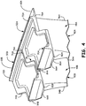
- FIG. 4 is a perspective view of outer shrouds 52A and 52B of turbine blades 42A and 42B with corners 80A and 80B (shown in FIG. 3 ) cut off.
- Outer shroud 52A includes machined cut 84A extending from leading edge 86A of leading edge overhang 66A to mate face 74A.
- Machined cut 84A creates a diagonal edge that connects to the mate face 74A axially aft of leading edge 54A of airfoil 48A.
- Machined cut 84A shortens leading edge overhang 66A.
- Machined cut 84A substantially eliminates leading edge overhang 66A at mate face 74A but leaves leading edge overhang 66A at mate face 76A.
- Machined cut 84A can be substantially adjacent curved fillet 64A (shown in FIG. 2 ).
- Machined cut 84A is not complimentary to the z-lock shape of mate face 76B, but rather extends away from
- Machined cut 84A can shorten front knife edge seal 70A.
- front knife edge seal 70A is positioned such that machined cut 84A cuts a portion of front knife edge seal 70A in addition to leading edge overhang 66A.
- front knife edge seal 70A can be positioned such that machined cut 84A cuts leading edge overhang 66A, but not front knife edge seal 70A.
- Machined cut 84B can be substantially the same as machined cut 84A, such that outer shroud 52B has substantially the same shape as outer shroud 52A.
- machined cuts 84A and 84B can be positioned and/or shaped differently than illustrated. For example, in one embodiment machined cuts 84A and 84B can cut off corners 82A and 82B as opposed to corners 80A and 80B.
- machined cut 84A can alter the vibration mode shape of turbine blade 42A such that an undesirable anti-node does not form at corner 80A. This can reduce undesirable vibration characteristics of turbine blade 42A, and potentially extend the useful life of turbine blade 42A.
- Machined cut 84A can be made on turbine blade 42A that is already physically formed (as shown in FIG. 3 ), and thus allow for vibration characteristics to be corrected on an existing turbine blade 42A without having to redesign and reform a new turbine blade.
- gas turbine engine 10 and its various components need not be configured precisely as illustrated, but can be configured as appropriate for a particular application.
Landscapes
- Engineering & Computer Science (AREA)
- Mechanical Engineering (AREA)
- General Engineering & Computer Science (AREA)
- Architecture (AREA)
- Turbine Rotor Nozzle Sealing (AREA)
Description
- The present invention relates to gas turbine engines, and in particular, to turbine blades used in gas turbine engines.
- Gas turbine engines typically include one or more compressor sections and turbine sections. The compressor and turbine sections can include a number of airfoils, including rotating blades and stationary vanes. Various components in gas turbine engines can experience vibration conditions during operation of the gas turbine engines. Certain vibration characteristics can be damaging to engine components. For example, in some gas turbine engines, turbine blades can be damaged by certain vibration characteristics. Such damage can shorten the useful life of turbine blades and possibly cause failure of the gas turbine engine.
-
US 5498136 andUS 5156529 may be useful in understanding the background of the present disclosure. - According to the present invention, a method is provided as defined in claim 1.
- Another embodiment is a shrouded turbine blade as defined in
claim 10. -
-
FIG. 1 is a side sectional schematic view of an industrial gas turbine engine. -
FIG. 2 is a side view of a turbine blade for use in the industrial gas turbine engine ofFIG. 1 . -
FIG. 3 is a perspective view of outer diameter shrouds on turbine blades as inFIG. 2 , prior to cutting a corner of the shrouds. -
FIG. 4 is a perspective view of the outer diameter shrouds ofFIG. 3 , each with a corner cut off. -
FIG. 1 is a side partial sectional schematic view ofgas turbine engine 10. In the illustrated embodiment,gas turbine engine 10 is an industrial gas turbine engine circumferentially disposed about a central, longitudinal axis or axialengine centerline axis 12 as illustrated inFIG. 1 .Gas turbine engine 10 includes in series order from front to rear, lowpressure compressor section 16, highpressure compressor section 18,combustor section 20, highpressure turbine section 22, and lowpressure turbine section 24. In some embodiments,power turbine section 26 is a free turbine section disposed aft of the lowpressure turbine section 24. - As is well known in the art of gas turbines, incoming
ambient air 30 becomespressurized air 32 in the low andhigh pressure compressors air 32 incombustor section 20, where it is burned. Once burned,combustion gases 34 expand through high and lowpressure turbine sections power turbine section 26. High and lowpressure turbine sections pressure rotor shafts pressure compressor sections Power turbine section 26 may, for example, drive an electrical generator, pump, or gearbox (not shown). - Low
pressure turbine section 24 includesturbine stage 40, which includes a plurality ofturbine blades 42, which are circumferentially disposed about axialengine centerline axis 12.Turbine blades 42 are connected to and rotate with lowpressure rotor shaft 38.Turbine blades 42 are spaced axially betweenstator vanes pressure rotor shaft 38. -
FIG. 2 is a side view ofturbine blade 42A, which is one of the circumferentially disposed turbine blades 42 (shown inFIG. 1 ) of gas turbine engine 10 (shown inFIG. 1 ). In the illustrated embodiment,turbine blade 42A is a component of low pressure turbine section 24 (shown inFIG. 1 ). In alternative embodiments,turbine blade 42A can be used in high pressure turbine section 22 (shown inFIG. 1 ) and/or power turbine section 26 (shown inFIG. 1 ). -
Turbine blade 42A is a shrouded turbine blade that includesairfoil 48A extending frominner shroud 50A toouter shroud 52A. Airfoil 48A has leadingedge 54A positioned axially forward of trailingedge 56A.Inner shroud 50A is connected to radiallyinner end 58A ofairfoil 48A.Outer shroud 52A is connected to radiallyouter end 60A ofairfoil 48A.Inner shroud 50A andouter shroud 52A define a radially inner and outer extent of a flow path throughturbine stage 40 of lowpressure compressor section 24.Rotor connection 62A is positioned radially inward ofinner shroud 50A for connectingturbine blade 42A to lowpressure rotor shaft 38. -
Outer shroud 52A is connected toairfoil 48A at acurved fillet 64A.Outer shroud 52A includes leadingedge overhang 66A extending axially forward of leadingedge 54A andtrailing edge overhang 68A extending axially aft oftrailing edge 56A. Frontknife edge seal 70A extends radially outward fromouter shroud 52A near leadingedge overhang 66A. Frontknife edge seal 70A is substantially perpendicular to leadingedge overhang 66A. Rearknife edge seal 72A extends radially outward fromouter shroud 52A neartrailing edge overhang 68A. -
FIG. 3 is a perspective view ofouter shrouds turbine blades Turbine blade 42B is substantially the same asturbine blade 42A, except thatturbine blade 42B is positionedadjacent turbine blade 42A.Turbine blades turbine blades 42 in turbine stage 40 (shown inFIG. 1 ). -
Outer shroud 52A includesopposite mate faces Mate face 74A is a hard (relatively thick) mate face andmate face 76A is a non-hard (relatively thin) mate face. Similarly,outer shroud 52B includesopposite mate faces Mate face 74B is a hard (relatively thick) mate face andmate face 76B is a non-hard (relatively thin) mate face. Mate faces 74A and 74B have a first z-lock shape. Mate faces 76A and 76B have a second z-lock shape that is complimentary to the first z-lock shape ofmate faces face 74Aabuts mate face 76B to combine to form z-lock connection 78. Z-lock connection 78 holdsturbine blades turbine stage 40. Although only twoturbine blades FIG. 3 , additional turbine blades (not shown) can be connectedadjacent mate faces turbine stage 40. - In operation, various components of gas turbine engine 10 (shown in
FIG. 1 ) can experience undesirable vibration. For example, turbine blades, such asturbine blades outer shroud 52A (andouter shroud 52B). Undesirable vibration characteristics forming oncorner 80A and/or 82A of leadingedge overhang 66A can shorten the useful life ofturbine blades gas turbine engine 10. - Risk of damage to
turbine blade 42A due to vibration can be reduced by first determining a vibration characteristic ofturbine blade 42A. In one embodiment, the vibration characteristic can be determined analytically. Turbineblade 42A can be modeled via modeling software and vibration characteristics can be simulated. In an alternative embodiment, the vibration characteristic can be determined experimentally.Turbine blade 42A can be physically manufactured, and vibration characteristics can be tested. - Whether performed analytically or experimentally, one can determine whether
turbine blade 42A has an undesirable vibration characteristic, such as a vibration mode shape with an anti-node atcorner 80A and/or 80B. Ifturbine blade 42A has a vibration mode shape with an anti-node atcorner 80A and/or 80B, leadingedge overhang 66A can vibrate in a way so as to damageturbine blade 42A.Turbine blade 42A can then be modified by cutting offcorner 80A and/or 80B where the anti-node is positioned. For example, if an undesirable anti-node is determined to be positioned atcorner 80A,turbine blade 42A can be manufactured such thatouter shroud 52A is shaped as shown inFIG. 3 and then machined to removecorner 80A such thatouter shroud 52A is shaped as shown inFIG. 4 . -
FIG. 4 is a perspective view ofouter shrouds turbine blades corners FIG. 3 ) cut off.Outer shroud 52A includes machinedcut 84A extending from leadingedge 86A of leadingedge overhang 66A to mateface 74A. Machined cut 84A creates a diagonal edge that connects to themate face 74A axially aft of leadingedge 54A ofairfoil 48A. Machined cut 84A shortens leadingedge overhang 66A. Machined cut 84A substantially eliminates leadingedge overhang 66A atmate face 74A but leaves leadingedge overhang 66A atmate face 76A. Machined cut 84A can be substantially adjacentcurved fillet 64A (shown inFIG. 2 ). Machined cut 84A is not complimentary to the z-lock shape ofmate face 76B, but rather extends away frommate face 76B. - Machined cut 84A can shorten front
knife edge seal 70A. In the illustrated embodiment, frontknife edge seal 70A is positioned such thatmachined cut 84A cuts a portion of frontknife edge seal 70A in addition to leadingedge overhang 66A. In alternative embodiments, frontknife edge seal 70A can be positioned such thatmachined cut 84A cuts leadingedge overhang 66A, but not frontknife edge seal 70A. Machined cut 84B can be substantially the same asmachined cut 84A, such thatouter shroud 52B has substantially the same shape asouter shroud 52A. In alternative embodiments, machinedcuts cuts corners corners - Thus, machined cut 84A can alter the vibration mode shape of
turbine blade 42A such that an undesirable anti-node does not form atcorner 80A. This can reduce undesirable vibration characteristics ofturbine blade 42A, and potentially extend the useful life ofturbine blade 42A. Machined cut 84A can be made onturbine blade 42A that is already physically formed (as shown inFIG. 3 ), and thus allow for vibration characteristics to be corrected on an existingturbine blade 42A without having to redesign and reform a new turbine blade. - While the invention has been described with reference to exemplary embodiments, it will be understood by those skilled in the art that various changes may be made and equivalents may be substituted for elements thereof without departing from the scope of the invention as defined by the appended claims.
- In addition, many modifications may be made to adapt a particular situation or material to the teachings of the invention without departing from the essential scope thereof. Therefore, it is intended that the invention not be limited to the particular embodiments disclosed, but that the invention will include all embodiments falling within the scope of the appended claims. For example,
gas turbine engine 10 and its various components need not be configured precisely as illustrated, but can be configured as appropriate for a particular application.
Claims (14)
- A method comprising: providing a shrouded turbine blade (42A);
determining a vibration characteristic of the shrouded turbine blade (42A) that comprises an airfoil (48A) attached to a shroud (52A),
characterized by further comprising:identifying an anti-node of the vibration characteristic, wherein the anti-node is located at a corner (80A, 80B) of the shrouded turbine blade (42A); andremoving the corner (80A, 80B) of the shrouded turbine blade (42A) after determining the vibration characteristic. - The method of claim 1, wherein removing the corner (80A, 80B) of the shrouded turbine blade (42A) comprises cutting a leading edge overhang (66A) of the shroud (52A).
- The method of claim 2, wherein removing the corner (80A, 80B) of the shrouded turbine blade (42A) comprises cutting a knife edge seal (72A) that extends radially outward from the shroud (52A).
- The method of any preceding claim, wherein the vibration characteristic of the shrouded turbine blade (42A) is determined experimentally.
- The method of any of claims 1 to 3, wherein the vibration characteristic of the shrouded turbine blade (42A) is determined analytically.
- The method of any preceding claim, wherein determining the vibration characteristic of the shrouded turbine blade (42A) comprises determining whether the shrouded turbine blade (42A) has a vibration mode shape with an anti-node at the corner (80A, 80B).
- The method of any preceding claim, wherein the shroud (52A) is an outer shroud attached to an outer end of the airfoil (48A).
- The method of any preceding claim, wherein the corner (80A, 80B) is cut substantially adjacent a curved fillet (64A) connecting the airfoil (48A) to the shroud (52A).
- The method of any preceding claim, wherein removing the corner (80A, 80B) of the shrouded turbine blade (42A) comprises machining the shrouded turbine blade (42A) after it has been physically formed.
- A shrouded turbine blade (42A) comprising:an airfoil (48A) having an outer end (60A); andan outer shroud (52A) attached to the outer end (60A), wherein the outer shroud (52A) comprises:a first mate face (74A) having a first z-lock shape;a second mate face (76A) opposite the first mate face and having a second z-lock shape that is complementary to the first z-lock shape; anda leading edge (54A),characterized by:a machined cut (84A) that removes a corner (80A, 80B) of the outer shroud (52A) that extends from the leading edge (54A) to the second mate face (76A), wherein vibration characteristics of the shrouded turbine blade (42A) in a pre-machined state includes an anti-node at the corner (80A, 80B).
- The shrouded turbine blade (42A) of claim 10, wherein the first z-lock shape of the first mate face (74A) is not complimentary to the machined cut (84A).
- The shrouded turbine blade (42A) of claim 10 or 11, wherein the machined cut (84A) shortens a leading edge overhang (66A) and a knife edge seal (72A) that extends radially outward from the outer shroud (52A).
- The shrouded turbine blade (42A) of any of claims 10, 11 or 12, wherein the machined cut (84A) is substantially adjacent a curved fillet (64A) connecting the airfoil (48A) to the outer shroud (52A).
- The shrouded turbine blade (42A) of any of claims 10 to 13, wherein the machined cut (84A) is a substantially straight and diagonal cut.
Applications Claiming Priority (2)
| Application Number | Priority Date | Filing Date | Title |
|---|---|---|---|
| US201261746766P | 2012-12-28 | 2012-12-28 | |
| PCT/US2013/075817 WO2014105533A1 (en) | 2012-12-28 | 2013-12-17 | Shrouded turbine blade with cut corner |
Publications (3)
| Publication Number | Publication Date |
|---|---|
| EP2938832A1 EP2938832A1 (en) | 2015-11-04 |
| EP2938832A4 EP2938832A4 (en) | 2016-08-10 |
| EP2938832B1 true EP2938832B1 (en) | 2019-02-06 |
Family
ID=51021951
Family Applications (1)
| Application Number | Title | Priority Date | Filing Date |
|---|---|---|---|
| EP13867362.9A Active EP2938832B1 (en) | 2012-12-28 | 2013-12-17 | Shrouded turbine blade with cut corner |
Country Status (3)
| Country | Link |
|---|---|
| US (1) | US10125613B2 (en) |
| EP (1) | EP2938832B1 (en) |
| WO (1) | WO2014105533A1 (en) |
Families Citing this family (3)
| Publication number | Priority date | Publication date | Assignee | Title |
|---|---|---|---|---|
| KR101874243B1 (en) * | 2017-03-31 | 2018-07-03 | 두산중공업 주식회사 | Structure for damping vibration of bucket and turbo machine having the same |
| DE102018201265A1 (en) | 2018-01-29 | 2019-08-01 | MTU Aero Engines AG | Shroud segment for placement on a blade of a turbomachine and blade |
| EP3865665A1 (en) | 2020-02-11 | 2021-08-18 | MTU Aero Engines AG | Blade for a turbomachine with a shroud |
Family Cites Families (19)
| Publication number | Priority date | Publication date | Assignee | Title |
|---|---|---|---|---|
| US5097711A (en) | 1990-10-29 | 1992-03-24 | Westinghouse Electric Corp. | Shrouded turbine blade vibration monitor and target therefor |
| US5156529A (en) * | 1991-03-28 | 1992-10-20 | Westinghouse Electric Corp. | Integral shroud blade design |
| JP3107266B2 (en) | 1993-09-17 | 2000-11-06 | 株式会社日立製作所 | Fluid machinery and wing devices for fluid machinery |
| US5522705A (en) * | 1994-05-13 | 1996-06-04 | United Technologies Corporation | Friction damper for gas turbine engine blades |
| JPH08303204A (en) * | 1995-05-08 | 1996-11-19 | Ishikawajima Harima Heavy Ind Co Ltd | Gas turbine rotor blade seal structure |
| US6164916A (en) * | 1998-11-02 | 2000-12-26 | General Electric Company | Method of applying wear-resistant materials to turbine blades, and turbine blades having wear-resistant materials |
| US6471482B2 (en) | 2000-11-30 | 2002-10-29 | United Technologies Corporation | Frequency-mistuned light-weight turbomachinery blade rows for increased flutter stability |
| JP4087729B2 (en) | 2003-03-24 | 2008-05-21 | 本田技研工業株式会社 | Vibration suppression device for gas turbine engine |
| DE102005006414A1 (en) * | 2005-02-12 | 2006-08-24 | Mtu Aero Engines Gmbh | A method of machining an integrally bladed rotor |
| US7753652B2 (en) | 2006-12-15 | 2010-07-13 | Siemens Energy, Inc. | Aero-mixing of rotating blade structures |
| US7975354B2 (en) | 2007-02-08 | 2011-07-12 | United Technologies Corporation | Bladed disk assembly method and impact device |
| US7861592B2 (en) * | 2007-02-27 | 2011-01-04 | Siemens Energy, Inc. | Blade shroud vibration monitor |
| US7887295B2 (en) | 2007-11-08 | 2011-02-15 | General Electric Company | Z-Notch shape for a turbine blade |
| US7976280B2 (en) * | 2007-11-28 | 2011-07-12 | General Electric Company | Turbine bucket shroud internal core profile |
| US8292580B2 (en) * | 2008-09-18 | 2012-10-23 | Siemens Energy, Inc. | CMC vane assembly apparatus and method |
| US8313301B2 (en) | 2009-01-30 | 2012-11-20 | United Technologies Corporation | Cooled turbine blade shroud |
| US8172511B2 (en) | 2009-05-04 | 2012-05-08 | Hamilton Sunstrand Corporation | Radial compressor with blades decoupled and tuned at anti-nodes |
| US8951014B2 (en) | 2011-03-15 | 2015-02-10 | United Technologies Corporation | Turbine blade with mate face cooling air flow |
| US8876479B2 (en) | 2011-03-15 | 2014-11-04 | United Technologies Corporation | Damper pin |
-
2013
- 2013-12-17 WO PCT/US2013/075817 patent/WO2014105533A1/en not_active Ceased
- 2013-12-17 US US14/650,090 patent/US10125613B2/en active Active
- 2013-12-17 EP EP13867362.9A patent/EP2938832B1/en active Active
Non-Patent Citations (1)
| Title |
|---|
| None * |
Also Published As
| Publication number | Publication date |
|---|---|
| EP2938832A4 (en) | 2016-08-10 |
| US10125613B2 (en) | 2018-11-13 |
| WO2014105533A1 (en) | 2014-07-03 |
| US20150315918A1 (en) | 2015-11-05 |
| EP2938832A1 (en) | 2015-11-04 |
Similar Documents
| Publication | Publication Date | Title |
|---|---|---|
| US7887299B2 (en) | Rotary body for turbo machinery with mistuned blades | |
| EP1890008B1 (en) | Rotor blade | |
| US7922444B2 (en) | Chamfer rail pockets for turbine vane shrouds | |
| US20190128126A1 (en) | Turbine blisk and method of manufacturing thereof | |
| EP3225794A1 (en) | Turbine engine shroud assembly | |
| EP4130430B1 (en) | Integrated bladed rotor | |
| US10018075B2 (en) | Methods for positioning neighboring nozzles of a gas turbine engine | |
| CA2881943C (en) | Turbine blade for a gas turbine engine | |
| WO2014130116A2 (en) | Turbine blade apparatus | |
| US20200011185A1 (en) | Turbine Engine and Method of Assembling | |
| EP3009598B1 (en) | Tandem rotor blades | |
| EP3181945B1 (en) | Damper seal installation features | |
| US10125613B2 (en) | Shrouded turbine blade with cut corner | |
| EP2998516B1 (en) | Gas turbine engine | |
| US9896947B2 (en) | Turbine airfoil attachment with multi-radial serration profile | |
| EP3399146B1 (en) | Method of manufacturing a vane arrangement for a gas turbine engine | |
| WO2013150263A1 (en) | Axial flow turbine blisc | |
| CN107806367B (en) | Rotatable machine and turbofan for preventing overspeed of rotor disc | |
| EP3550111A1 (en) | Turbine blade shroud for gas turbine engine with power turbine and method of manufacturing same | |
| EP4726174A1 (en) | Mitigation strategy for airfoil cracks for integrally bladed rotors | |
| EP3190269A1 (en) | Low energy wake stage | |
| EP3059389A1 (en) | Gas turbine rotor disc with assymetric circumferential slot |
Legal Events
| Date | Code | Title | Description |
|---|---|---|---|
| PUAI | Public reference made under article 153(3) epc to a published international application that has entered the european phase |
Free format text: ORIGINAL CODE: 0009012 |
|
| 17P | Request for examination filed |
Effective date: 20150727 |
|
| AK | Designated contracting states |
Kind code of ref document: A1 Designated state(s): AL AT BE BG CH CY CZ DE DK EE ES FI FR GB GR HR HU IE IS IT LI LT LU LV MC MK MT NL NO PL PT RO RS SE SI SK SM TR |
|
| AX | Request for extension of the european patent |
Extension state: BA ME |
|
| RIN1 | Information on inventor provided before grant (corrected) |
Inventor name: CORCORAN, CHRISTOPHER Inventor name: SAVAGE, ERIC S. |
|
| DAX | Request for extension of the european patent (deleted) | ||
| RIN1 | Information on inventor provided before grant (corrected) |
Inventor name: CORCORAN, CHRISTOPHER Inventor name: SAVAGE, ERIC S. |
|
| A4 | Supplementary search report drawn up and despatched |
Effective date: 20160708 |
|
| RIC1 | Information provided on ipc code assigned before grant |
Ipc: F01C 7/00 20060101ALI20160704BHEP Ipc: F01D 5/26 20060101ALI20160704BHEP Ipc: F01D 5/22 20060101AFI20160704BHEP |
|
| RAP1 | Party data changed (applicant data changed or rights of an application transferred) |
Owner name: UNITED TECHNOLOGIES CORPORATION |
|
| REG | Reference to a national code |
Ref country code: DE Ref legal event code: R079 Ref document number: 602013050635 Country of ref document: DE Free format text: PREVIOUS MAIN CLASS: F01D0005220000 Ipc: F01D0005140000 |
|
| GRAP | Despatch of communication of intention to grant a patent |
Free format text: ORIGINAL CODE: EPIDOSNIGR1 |
|
| STAA | Information on the status of an ep patent application or granted ep patent |
Free format text: STATUS: GRANT OF PATENT IS INTENDED |
|
| RIC1 | Information provided on ipc code assigned before grant |
Ipc: F01D 5/22 20060101ALI20180710BHEP Ipc: F01D 25/06 20060101ALI20180710BHEP Ipc: F01D 5/14 20060101AFI20180710BHEP Ipc: F01D 5/16 20060101ALI20180710BHEP Ipc: F01D 5/26 20060101ALI20180710BHEP |
|
| INTG | Intention to grant announced |
Effective date: 20180802 |
|
| GRAS | Grant fee paid |
Free format text: ORIGINAL CODE: EPIDOSNIGR3 |
|
| GRAA | (expected) grant |
Free format text: ORIGINAL CODE: 0009210 |
|
| STAA | Information on the status of an ep patent application or granted ep patent |
Free format text: STATUS: THE PATENT HAS BEEN GRANTED |
|
| AK | Designated contracting states |
Kind code of ref document: B1 Designated state(s): AL AT BE BG CH CY CZ DE DK EE ES FI FR GB GR HR HU IE IS IT LI LT LU LV MC MK MT NL NO PL PT RO RS SE SI SK SM TR |
|
| REG | Reference to a national code |
Ref country code: GB Ref legal event code: FG4D |
|
| REG | Reference to a national code |
Ref country code: CH Ref legal event code: EP Ref country code: AT Ref legal event code: REF Ref document number: 1095036 Country of ref document: AT Kind code of ref document: T Effective date: 20190215 |
|
| REG | Reference to a national code |
Ref country code: IE Ref legal event code: FG4D |
|
| REG | Reference to a national code |
Ref country code: DE Ref legal event code: R096 Ref document number: 602013050635 Country of ref document: DE |
|
| REG | Reference to a national code |
Ref country code: NL Ref legal event code: MP Effective date: 20190206 |
|
| REG | Reference to a national code |
Ref country code: LT Ref legal event code: MG4D |
|
| PG25 | Lapsed in a contracting state [announced via postgrant information from national office to epo] |
Ref country code: LT Free format text: LAPSE BECAUSE OF FAILURE TO SUBMIT A TRANSLATION OF THE DESCRIPTION OR TO PAY THE FEE WITHIN THE PRESCRIBED TIME-LIMIT Effective date: 20190206 Ref country code: NL Free format text: LAPSE BECAUSE OF FAILURE TO SUBMIT A TRANSLATION OF THE DESCRIPTION OR TO PAY THE FEE WITHIN THE PRESCRIBED TIME-LIMIT Effective date: 20190206 Ref country code: FI Free format text: LAPSE BECAUSE OF FAILURE TO SUBMIT A TRANSLATION OF THE DESCRIPTION OR TO PAY THE FEE WITHIN THE PRESCRIBED TIME-LIMIT Effective date: 20190206 Ref country code: NO Free format text: LAPSE BECAUSE OF FAILURE TO SUBMIT A TRANSLATION OF THE DESCRIPTION OR TO PAY THE FEE WITHIN THE PRESCRIBED TIME-LIMIT Effective date: 20190506 Ref country code: SE Free format text: LAPSE BECAUSE OF FAILURE TO SUBMIT A TRANSLATION OF THE DESCRIPTION OR TO PAY THE FEE WITHIN THE PRESCRIBED TIME-LIMIT Effective date: 20190206 Ref country code: PT Free format text: LAPSE BECAUSE OF FAILURE TO SUBMIT A TRANSLATION OF THE DESCRIPTION OR TO PAY THE FEE WITHIN THE PRESCRIBED TIME-LIMIT Effective date: 20190606 |
|
| REG | Reference to a national code |
Ref country code: AT Ref legal event code: MK05 Ref document number: 1095036 Country of ref document: AT Kind code of ref document: T Effective date: 20190206 |
|
| PG25 | Lapsed in a contracting state [announced via postgrant information from national office to epo] |
Ref country code: LV Free format text: LAPSE BECAUSE OF FAILURE TO SUBMIT A TRANSLATION OF THE DESCRIPTION OR TO PAY THE FEE WITHIN THE PRESCRIBED TIME-LIMIT Effective date: 20190206 Ref country code: IS Free format text: LAPSE BECAUSE OF FAILURE TO SUBMIT A TRANSLATION OF THE DESCRIPTION OR TO PAY THE FEE WITHIN THE PRESCRIBED TIME-LIMIT Effective date: 20190606 Ref country code: GR Free format text: LAPSE BECAUSE OF FAILURE TO SUBMIT A TRANSLATION OF THE DESCRIPTION OR TO PAY THE FEE WITHIN THE PRESCRIBED TIME-LIMIT Effective date: 20190507 Ref country code: RS Free format text: LAPSE BECAUSE OF FAILURE TO SUBMIT A TRANSLATION OF THE DESCRIPTION OR TO PAY THE FEE WITHIN THE PRESCRIBED TIME-LIMIT Effective date: 20190206 Ref country code: HR Free format text: LAPSE BECAUSE OF FAILURE TO SUBMIT A TRANSLATION OF THE DESCRIPTION OR TO PAY THE FEE WITHIN THE PRESCRIBED TIME-LIMIT Effective date: 20190206 Ref country code: BG Free format text: LAPSE BECAUSE OF FAILURE TO SUBMIT A TRANSLATION OF THE DESCRIPTION OR TO PAY THE FEE WITHIN THE PRESCRIBED TIME-LIMIT Effective date: 20190506 |
|
| PG25 | Lapsed in a contracting state [announced via postgrant information from national office to epo] |
Ref country code: ES Free format text: LAPSE BECAUSE OF FAILURE TO SUBMIT A TRANSLATION OF THE DESCRIPTION OR TO PAY THE FEE WITHIN THE PRESCRIBED TIME-LIMIT Effective date: 20190206 Ref country code: AL Free format text: LAPSE BECAUSE OF FAILURE TO SUBMIT A TRANSLATION OF THE DESCRIPTION OR TO PAY THE FEE WITHIN THE PRESCRIBED TIME-LIMIT Effective date: 20190206 Ref country code: CZ Free format text: LAPSE BECAUSE OF FAILURE TO SUBMIT A TRANSLATION OF THE DESCRIPTION OR TO PAY THE FEE WITHIN THE PRESCRIBED TIME-LIMIT Effective date: 20190206 Ref country code: RO Free format text: LAPSE BECAUSE OF FAILURE TO SUBMIT A TRANSLATION OF THE DESCRIPTION OR TO PAY THE FEE WITHIN THE PRESCRIBED TIME-LIMIT Effective date: 20190206 Ref country code: SK Free format text: LAPSE BECAUSE OF FAILURE TO SUBMIT A TRANSLATION OF THE DESCRIPTION OR TO PAY THE FEE WITHIN THE PRESCRIBED TIME-LIMIT Effective date: 20190206 Ref country code: DK Free format text: LAPSE BECAUSE OF FAILURE TO SUBMIT A TRANSLATION OF THE DESCRIPTION OR TO PAY THE FEE WITHIN THE PRESCRIBED TIME-LIMIT Effective date: 20190206 Ref country code: EE Free format text: LAPSE BECAUSE OF FAILURE TO SUBMIT A TRANSLATION OF THE DESCRIPTION OR TO PAY THE FEE WITHIN THE PRESCRIBED TIME-LIMIT Effective date: 20190206 Ref country code: IT Free format text: LAPSE BECAUSE OF FAILURE TO SUBMIT A TRANSLATION OF THE DESCRIPTION OR TO PAY THE FEE WITHIN THE PRESCRIBED TIME-LIMIT Effective date: 20190206 |
|
| REG | Reference to a national code |
Ref country code: DE Ref legal event code: R097 Ref document number: 602013050635 Country of ref document: DE |
|
| PG25 | Lapsed in a contracting state [announced via postgrant information from national office to epo] |
Ref country code: SM Free format text: LAPSE BECAUSE OF FAILURE TO SUBMIT A TRANSLATION OF THE DESCRIPTION OR TO PAY THE FEE WITHIN THE PRESCRIBED TIME-LIMIT Effective date: 20190206 Ref country code: PL Free format text: LAPSE BECAUSE OF FAILURE TO SUBMIT A TRANSLATION OF THE DESCRIPTION OR TO PAY THE FEE WITHIN THE PRESCRIBED TIME-LIMIT Effective date: 20190206 |
|
| PLBE | No opposition filed within time limit |
Free format text: ORIGINAL CODE: 0009261 |
|
| STAA | Information on the status of an ep patent application or granted ep patent |
Free format text: STATUS: NO OPPOSITION FILED WITHIN TIME LIMIT |
|
| PG25 | Lapsed in a contracting state [announced via postgrant information from national office to epo] |
Ref country code: AT Free format text: LAPSE BECAUSE OF FAILURE TO SUBMIT A TRANSLATION OF THE DESCRIPTION OR TO PAY THE FEE WITHIN THE PRESCRIBED TIME-LIMIT Effective date: 20190206 |
|
| 26N | No opposition filed |
Effective date: 20191107 |
|
| PG25 | Lapsed in a contracting state [announced via postgrant information from national office to epo] |
Ref country code: SI Free format text: LAPSE BECAUSE OF FAILURE TO SUBMIT A TRANSLATION OF THE DESCRIPTION OR TO PAY THE FEE WITHIN THE PRESCRIBED TIME-LIMIT Effective date: 20190206 |
|
| PG25 | Lapsed in a contracting state [announced via postgrant information from national office to epo] |
Ref country code: TR Free format text: LAPSE BECAUSE OF FAILURE TO SUBMIT A TRANSLATION OF THE DESCRIPTION OR TO PAY THE FEE WITHIN THE PRESCRIBED TIME-LIMIT Effective date: 20190206 |
|
| REG | Reference to a national code |
Ref country code: CH Ref legal event code: PL |
|
| REG | Reference to a national code |
Ref country code: BE Ref legal event code: MM Effective date: 20191231 |
|
| PG25 | Lapsed in a contracting state [announced via postgrant information from national office to epo] |
Ref country code: MC Free format text: LAPSE BECAUSE OF FAILURE TO SUBMIT A TRANSLATION OF THE DESCRIPTION OR TO PAY THE FEE WITHIN THE PRESCRIBED TIME-LIMIT Effective date: 20190206 |
|
| PG25 | Lapsed in a contracting state [announced via postgrant information from national office to epo] |
Ref country code: LU Free format text: LAPSE BECAUSE OF NON-PAYMENT OF DUE FEES Effective date: 20191217 Ref country code: IE Free format text: LAPSE BECAUSE OF NON-PAYMENT OF DUE FEES Effective date: 20191217 |
|
| PG25 | Lapsed in a contracting state [announced via postgrant information from national office to epo] |
Ref country code: LI Free format text: LAPSE BECAUSE OF NON-PAYMENT OF DUE FEES Effective date: 20191231 Ref country code: CH Free format text: LAPSE BECAUSE OF NON-PAYMENT OF DUE FEES Effective date: 20191231 Ref country code: BE Free format text: LAPSE BECAUSE OF NON-PAYMENT OF DUE FEES Effective date: 20191231 |
|
| PG25 | Lapsed in a contracting state [announced via postgrant information from national office to epo] |
Ref country code: CY Free format text: LAPSE BECAUSE OF FAILURE TO SUBMIT A TRANSLATION OF THE DESCRIPTION OR TO PAY THE FEE WITHIN THE PRESCRIBED TIME-LIMIT Effective date: 20190206 |
|
| PG25 | Lapsed in a contracting state [announced via postgrant information from national office to epo] |
Ref country code: HU Free format text: LAPSE BECAUSE OF FAILURE TO SUBMIT A TRANSLATION OF THE DESCRIPTION OR TO PAY THE FEE WITHIN THE PRESCRIBED TIME-LIMIT; INVALID AB INITIO Effective date: 20131217 Ref country code: MT Free format text: LAPSE BECAUSE OF FAILURE TO SUBMIT A TRANSLATION OF THE DESCRIPTION OR TO PAY THE FEE WITHIN THE PRESCRIBED TIME-LIMIT Effective date: 20190206 |
|
| PG25 | Lapsed in a contracting state [announced via postgrant information from national office to epo] |
Ref country code: MK Free format text: LAPSE BECAUSE OF FAILURE TO SUBMIT A TRANSLATION OF THE DESCRIPTION OR TO PAY THE FEE WITHIN THE PRESCRIBED TIME-LIMIT Effective date: 20190206 |
|
| REG | Reference to a national code |
Ref country code: DE Ref legal event code: R081 Ref document number: 602013050635 Country of ref document: DE Owner name: RAYTHEON TECHNOLOGIES CORPORATION (N.D.GES.D.S, US Free format text: FORMER OWNER: UNITED TECHNOLOGIES CORPORATION, FARMINGTON, CONN., US Ref country code: DE Ref legal event code: R081 Ref document number: 602013050635 Country of ref document: DE Owner name: RTX CORPORATION (N.D.GES.D. STAATES DELAWARE),, US Free format text: FORMER OWNER: UNITED TECHNOLOGIES CORPORATION, FARMINGTON, CONN., US |
|
| P01 | Opt-out of the competence of the unified patent court (upc) registered |
Effective date: 20230520 |
|
| REG | Reference to a national code |
Ref country code: DE Ref legal event code: R081 Ref document number: 602013050635 Country of ref document: DE Owner name: RTX CORPORATION (N.D.GES.D. STAATES DELAWARE),, US Free format text: FORMER OWNER: RAYTHEON TECHNOLOGIES CORPORATION (N.D.GES.D.STAATES DELAWARE), ARLINGTON, VA, US |
|
| PGFP | Annual fee paid to national office [announced via postgrant information from national office to epo] |
Ref country code: DE Payment date: 20251126 Year of fee payment: 13 |
|
| PGFP | Annual fee paid to national office [announced via postgrant information from national office to epo] |
Ref country code: GB Payment date: 20251120 Year of fee payment: 13 |
|
| PGFP | Annual fee paid to national office [announced via postgrant information from national office to epo] |
Ref country code: FR Payment date: 20251120 Year of fee payment: 13 |