EP2938700B1 - Duct intersection incorporating a flow modifier and method for improving gas flow - Google Patents
Duct intersection incorporating a flow modifier and method for improving gas flow Download PDFInfo
- Publication number
- EP2938700B1 EP2938700B1 EP12890654.2A EP12890654A EP2938700B1 EP 2938700 B1 EP2938700 B1 EP 2938700B1 EP 12890654 A EP12890654 A EP 12890654A EP 2938700 B1 EP2938700 B1 EP 2938700B1
- Authority
- EP
- European Patent Office
- Prior art keywords
- duct
- flow
- intersection
- contoured
- wall
- Prior art date
- Legal status (The legal status is an assumption and is not a legal conclusion. Google has not performed a legal analysis and makes no representation as to the accuracy of the status listed.)
- Active
Links
Images


Classifications
-
- C—CHEMISTRY; METALLURGY
- C10—PETROLEUM, GAS OR COKE INDUSTRIES; TECHNICAL GASES CONTAINING CARBON MONOXIDE; FUELS; LUBRICANTS; PEAT
- C10B—DESTRUCTIVE DISTILLATION OF CARBONACEOUS MATERIALS FOR PRODUCTION OF GAS, COKE, TAR, OR SIMILAR MATERIALS
- C10B15/00—Other coke ovens
- C10B15/02—Other coke ovens with floor heating
-
- F—MECHANICAL ENGINEERING; LIGHTING; HEATING; WEAPONS; BLASTING
- F15—FLUID-PRESSURE ACTUATORS; HYDRAULICS OR PNEUMATICS IN GENERAL
- F15D—FLUID DYNAMICS, i.e. METHODS OR MEANS FOR INFLUENCING THE FLOW OF GASES OR LIQUIDS
- F15D1/00—Influencing flow of fluids
- F15D1/02—Influencing flow of fluids in pipes or conduits
- F15D1/04—Arrangements of guide vanes in pipe elbows or duct bends; Construction of pipe conduit elements for elbows with respect to flow, e.g. for reducing losses of flow
-
- F—MECHANICAL ENGINEERING; LIGHTING; HEATING; WEAPONS; BLASTING
- F23—COMBUSTION APPARATUS; COMBUSTION PROCESSES
- F23J—REMOVAL OR TREATMENT OF COMBUSTION PRODUCTS OR COMBUSTION RESIDUES; FLUES
- F23J11/00—Devices for conducting smoke or fumes, e.g. flues
-
- F—MECHANICAL ENGINEERING; LIGHTING; HEATING; WEAPONS; BLASTING
- F15—FLUID-PRESSURE ACTUATORS; HYDRAULICS OR PNEUMATICS IN GENERAL
- F15D—FLUID DYNAMICS, i.e. METHODS OR MEANS FOR INFLUENCING THE FLOW OF GASES OR LIQUIDS
- F15D1/00—Influencing flow of fluids
- F15D1/14—Diverting flow into alternative channels
Definitions
- the present technology is generally directed to devices and methods for modifying fluid flow within a duct. More specifically, some embodiments are directed to flow modifiers and transition portions for improving the exhaust flow from a coke oven through a duct intersection.
- Coke is a solid carbonaceous fuel that is derived from coal. Because of its relatively few impurities, coke is a favored energy source in a variety of useful applications. For example, coke is often used to smelt iron ores during the steelmaking process. As a further example, coke may also be used to heat commercial buildings or power industrial boilers.
- an amount of coal is baked in a coke oven at temperatures that typically exceed 2000 degrees Fahrenheit (1093.3 degrees Celsius).
- the baking process transforms the relatively impure coal into coke, which contains relatively few impurities.
- the coke typically emerges from the coke oven as a substantially intact piece.
- the coke typically is removed from the coke oven, loaded into one or more train cars (e.g., a hot car, a quench car, or a combined hot car/quench car), and transported to a quench tower in order to cool or "quench" the coke before it is made available for distribution for use as a fuel source.
- train cars e.g., a hot car, a quench car, or a combined hot car/quench car
- the hot exhaust i.e. flue gas
- the hot exhaust is extracted from the coke ovens through a network of ducts, intersections, and transitions.
- the intersections in the flue gas flow path of a coke plant can lead to significant pressure drop losses, poor flow zones (e.g. dead, stagnant, recirculation, separation, etc.), and poor mixing of air and volatile matter.
- the high pressure drop losses lead to higher required draft which can lead to leaks and a more difficult to control system.
- poor mixing and resulting localized hot spots can lead to earlier structural degradation due to accelerated localized erosion and thermal wear. Erosion includes deterioration due to high velocity flow eating away at material. Hot spots can lead to thermal degradation of material, which can eventually cause thermal/structural failure.
- This localized erosion and/or hot spots can, in turn, lead to failures at duct intersections.
- the intersection of a coke plant's vent stack and crossover duct is susceptible to poor mixing/flow distribution that can lead to hot spots resulting in tunnel failures.
- US 4 342 195 A discloses an exhaust system for a motorcycle.
- EP 0 126 399 A1 discloses a flow channel of short overall length.
- US 5 213 138 A discloses downstream extending convolutions disposed on the inside corner of an angled conduit.
- a duct intersection according to the present invention is provided according to claim 1.
- a method of improving gas flow in an exhaust system including at least one duct intersection according to the present invention is provided according to claim 5.
- a duct intersection comprises a first duct portion and a second duct portion extending laterally from a side of the first duct portion.
- the second duct portion may tee into the first duct portion.
- the second duct portion may extend laterally from the side of the first duct portion at an angle of less than 90 degrees.
- At least one flow modifier is mounted inside one of the first and second duct portions.
- the flow modifier is a contoured duct liner.
- the flow modifier includes at least one turning vane.
- the contoured duct liner comprises a first contoured wall mated to an inside surface of the duct and a second contoured wall mated to the first contoured wall.
- the contoured duct liner may be mounted inside the first duct portion.
- the contoured duct liner is mounted inside the second duct portion.
- the second contoured wall may comprise a refractory material.
- the contoured duct liner comprises a first wall contoured to mate with an inside surface of a duct intersection and a second wall attached to the first wall.
- the second wall is contoured to modify the direction of gas flow within the duct intersection.
- the second wall includes at least one convex surface.
- the duct intersection comprises a first duct portion and a second duct portion extending laterally from a side of the first duct portion.
- a transition portion extends between the first and second duct portions, wherein the transition portion has a length extending along a side of the first duct portion and a depth extending away from the side of the first duct portion.
- the length is a function of the diameter of the second duct portion.
- the length is greater than a diameter of the second duct portion.
- the length is twice the depth.
- the exhaust system comprises an emergency stack and a crossover duct extending laterally from a side of the emergency stack.
- the system also includes a contoured duct liner including a first wall mated to an inside surface of the emergency stack and a second wall attached to the first wall.
- the second wall is contoured to modify the direction of gas flow proximate an intersection of the emergency stack and crossover duct.
- the exhaust system may further comprise a second contoured duct liner mated to an inside surface of the crossover duct.
- the method may include determining a location of a poor flow zone (e.g. dead, stagnant, recirculation, separation, etc.) within the duct intersection and mounting a flow modifier in the duct intersection at the determined location.
- a location of a poor flow zone e.g. dead, stagnant, recirculation, separation, etc.
- the location is determined with a computer aided design system, such as a computational fluid dynamics (CFD) system.
- the location is determined by measuring conditions at the duct intersection, such as temperature, pressure, and/or velocity.
- CFD computational fluid dynamics
- a method of improving gas flow in an exhaust system including at least one duct intersection comprises determining a location of a poor flow zone within the duct intersection and injecting a fluid into the duct intersection at the determined location.
- a contoured duct liner, a duct intersection, and methods of improving gas flow in an exhaust system may be implemented as original designs or as retrofits to existing facilities.
- the disclosed designs have been found to improve flow, thermal conditions, and structural integrity at intersections or tie-ins in a coke oven or similar system.
- By optimizing the external and/or internal shape of intersections the mixing can be improved, areas of relatively undesirable conditions can be minimized, and pressure drop losses at the intersection can be minimized. Reducing pressure losses at the intersections can help lower draft set point(s), which can lead to improved operation as well as potentially lower cost designs and maintenance.
- it can be advantageous to minimize the draft set point of the overall system to minimize infiltration of any unwanted outside air into the system.
- FIG. 1 illustrates a representative coke plant 5 where coal 1 is fed into a battery of coke ovens 10 where the coal is heated to form coke.
- Exhaust gases i.e. flue gases
- Cross-over duct 16 is also connected to common tunnel 12 via the emergency stack 14.
- Hot flue gases flow through the cross-over duct 16 into a co-generation plant 18 which includes a heat recovery steam generator (HRSG) 20 which in turn feeds steam turbine 22.
- HRSG heat recovery steam generator
- the flue gases continue on to a sulfur treatment facility 24 and finally the treated exhaust gases are expelled through main stack 28 via duct fans 26, which provide negative pressure on the entire system in addition to the draft created by gases rising through the main stack 28.
- coke ovens 10 are connected to the common tunnel 12 via uptakes 15.
- Common tunnel 12 extends horizontally along the top of the coke ovens 10.
- An emergency stack 14 extends vertically from common tunnel 12 as shown.
- Cross-over duct 16 intersects emergency stack 14 at a duct intersection 30.
- the emergency stack 14 is closed whereby exhaust gases travel through the cross-over duct 16 to the co-generation plant 18 (see FIG. 1 ).
- the emergency stack 14 may be opened to allow exhaust gases to exit the system directly.
- the common tunnel 12 and cross-over duct 16 may intersect the emergency stack 14 at the same elevation.
- the technology disclosed herein may be applied to the intersections whether they are at the same elevation or different elevations.
- FIG. 3 illustrates various flow anomalies present in traditional duct intersections, such as duct intersection 30.
- Flow anomaly 32 is a point of localized combustion that is due to poor flow/distribution.
- An additional area of poor flow/mixing distribution 36 is located in the emergency stack 14 across from the cross-over duct 16.
- a poor flow zone 34 e.g. dead, stagnant, recirculation, separation, etc.
- These poor flow zone areas contain separated flows which can dissipate useful flow energy.
- These potential poor flow spaces can also contain unwanted, unsteady vortical flow, sometimes enhanced by buoyancy or chemical reactions, which can contribute to unwanted, poor acoustics, forced harmonics, potential flow instabilities, and incorrect instrument readings. Incorrect instrument readings may occur if measurements are made in a poor flow zone that has conditions not representative of flow in the duct. Because of the nature of the poor flow zones, these areas can also cause particle drop out and promote particle accumulation.
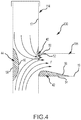
- FIG. 4 illustrates an improved duct intersection 130 according to an exemplary embodiment.
- Duct intersection 130 includes a first duct portion in the form of emergency stack 114 and a second duct portion in the form of cross-over duct 116 that extends laterally from a side of the emergency stack 114.
- duct intersection 130 includes a plurality of flow modifiers (40, 42, 44) to improve exhaust flow.
- flow modifier 40 is in the form of a contoured duct liner that is positioned at the intersection 130 of emergency stack 114 and cross-over duct 116.
- Flow modifier 40 occupies the area where traditional designs have poor flow and mixing such as flow anomaly 32 in FIG. 3 .
- Flow modifier 42 is disposed in cross-over duct 116 to occupy the poor flow zone 34 shown in FIG. 3 .
- Flow modifier 44 is disposed in the emergency stack 114 opposite the cross-over duct 116 and, in this case, occupies the poor mixing distribution region 36 shown in FIG. 3 . With the addition of flow modifiers 40, 42, and 44 the flow F within intersection 130 is improved (see FIG. 4 ).
- the duct liners reshape the internal contours of the duct, inherently changing the nature and direction of the flow path among other effects.
- the duct liners can be used to smooth or improve flow entrance or provide better transition from one path to another especially when there are limitations to do so with the duct shape.
- the contoured duct liners can be used to alleviate wall shear stress/erosion stemming from high velocities and particle accumulation from settling and/or particle impaction, which could result in slow or poor flow zones.
- the contoured duct liners also provide better duct transitions, or paths, for better flow transition and movement, mitigation of stress and thermal concentrations, and mitigation of flow separation, etc.
- the contoured duct liners 40, 42, and 44 are each comprised of a first contoured wall mated to an inside surface of the duct intersection and a second contoured wall mated to the first contoured wall.
- contoured duct liner 40 includes a first contoured wall 50 which is mated to the inside surface 17 of emergency stack 114 and inside surface 19 of cross-over duct 116.
- Duct liner 40 also includes a second contoured wall 52 that is mated to the first contoured wall 50.
- the second contoured wall 52 is convex and extends into the flow F of the flue gases traveling through the duct intersection 130.
- Contoured duct liner 42 includes a first contoured wall 54 which is mated to an inside surface 19 of the cross-over duct 116.
- a second contoured wall 56 is mated to the first contoured wall 54 and is also convex.
- contoured duct liner 44 includes a first contoured wall 58 mated to inside surface 17 of the emergency stack 114 and includes a second contoured wall 60 mated to the first contoured wall 58.
- first contoured walls of the contoured duct liners may be attached to the inside surfaces 17 and 19 by welding, fasteners, or the like.
- the second contoured walls may be attached to their respective first contoured walls by appropriate fasteners or by welding.
- the contoured duct liners may be comprised of various materials which are suitable for corrosive, high heat applications.
- first contoured walls 50, 54, and 58 may be comprised of steel or other suitable material.
- the second contoured walls 52, 56, and 60 may comprise a refractory material such as ceramic that is capable of resisting the heat associated with the flue gases and local combustion.
- the selection of materials can be dependent on the thermal, flow, and chemical properties of the flue gases. Because the flue gases can be of varied temperatures, velocities, chemical composition, in which all can depend on many factors such as the time in the coking cycle, flow control settings, ambient conditions, at the locations in the coking oven system, etc., the material selection can vary as well.
- the internal lining layers for the hot duct tie-ins could have more significant refractory layers than for cold ducts. Selection of appropriate materials may take into account min/max temperatures, thermal cycling, chemical reactions, flow erosion, acoustics, harmonics, resonance, condensation of corrosive chemicals, and accumulation of particles, for example.
- the flow modifiers may comprise a multilayer lining that is built up with a relatively inexpensive material and covered with a skin.
- refractory or similar material can be shaped via gunning (i.e. spraying). Better control of shaping via gunning may be accomplished by gunning in small increments or layers.
- a template or mold may be used to aid the shaping via gunning.
- a template, mold, or advanced cutting techniques may be used to shape the refractory (e.g. even in the absence of gunning for the main shape of an internal insert) for insertion into the duct and then attached via gunning to the inner lining of the duct.
- the flow modifier may be integrally formed along the duct.
- the duct wall may be formed or "dented" to provide a convex surface along the interior surface of the duct.
- convex does not require a continuous smooth surface, although a smooth surface may be desirable.
- the flow modifiers may be in the form of a multi-faceted protrusion extending into the flow path. Such a protrusion may be comprised of multiple discontinuous panels and/or surfaces.
- the flow modifiers are not limited to convex surfaces.
- the contours of the flow modifiers may have other complex surfaces that may be determined by CFD analysis and testing, and can be determined by design considerations such as cost, space, operating conditions, etc.
- FIG. 5 illustrates a traditional fan manifold 70 that extends between the duct fans 26 and main stack 28 (see FIG. 1 ).
- Fan manifold 70 comprises a plurality of branches 72, 74, and 76 which all intersect into plenum 80. As shown in the figure, branches 74 and 76 include flow diverters 78 while plenum 80 includes flow straightener 79.
- FIG. 6 which indicates velocity magnitude in the fan manifold 70
- traditional fan manifold designs result in a high velocity flow 82 which can damage the duct as a result of high shear stress.
- FIG. 7 illustrates a fan plenum 180 intersection which includes a turning vane assembly 90.
- the magnitude of the velocity flowing next to the surface of main stack 128 is much lower than in the conventional duct configuration shown in FIG. 6 .
- the higher flow velocity 184 is displaced inward away from the inside wall of the main stack 128, thereby reducing shear stress on the wall and helping to prevent erosion and corrosion of the stack.
- Turning vanes inside the duct help direct the flow path for a more efficient process. Turning vanes can be used to better mix flow, better directing of flow, and mitigation of total pressure losses, for example.
- the turning vane assembly 90 includes an inner vane 92 and an outer vane 94. In this embodiment, both the inner and outer vanes are disposed in the main stack 128.
- FIG. 8 provides exemplary dimensions by which a turning vane assembly could be constructed. However, these dimensions are exemplary and other dimensions and angles may be used.
- the inner vane 92 includes a leading portion 902 that connects to an angled portion 904, which, in turn, connects to trailing portion 906. As shown in the figure, the angled portion 904 tapers from a 100 inch width (2.54 metres) to an 80 inch width (2.03 metres).
- the trailing portion 906 tapers from an 80 inch width (2.03 metres) to a 50 inch width (1.27 metres).
- the dimensions are only representative and may vary.
- the angled portion 904 is angled at approximately 45 degrees; however, other angles may be used depending on the particular application.
- Outer vane 94 includes a leading portion 908 connected to an angled portion 910 which in turn is connected to a trailing portion 912.
- Outer turning vane 94 also includes side walls 914 and 916 as shown. Side walls 914 and 916 are canted inward towards the angled and trailing portions 910 and 912 at an angle A. In this embodiment angle A is approximately 10 degrees.
- Turning vane assembly 90 may be mounted or assembled into the main stack 128 with suitable fasteners or may be welded in place, for example.
- a fan manifold plenum 280 intersects main stack 228 with a ramped transition.
- the fan manifold plenum 280 has an upper wall 281 which transitions into the main stack 228 at an angle. As shown by the velocity magnitude 282, this results in a lower flow velocity magnitude than with traditional fan manifold designs shown in FIGS. 5 and 6 . It has been found that improving the intersection/transition from the duct fan to the main stack can reduce wear and erosion as well as ash buildup in the main stack.
- contoured duct liners and/or turning vanes may be used together in combination. For example, contoured duct liners may be located in the slower velocity regions 202, 204, and 206 as shown in FIG. 10 .
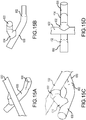
- FIGS. 11A and 11B illustrate a duct intersection 230 according to another exemplary embodiment.
- the duct intersection 230 includes an emergency stack 214 and a cross-over duct 216 with a transition portion 240 extending therebetween.
- Changing the size of the duct cross sectional areas near or at intersections can help improve flow performance.
- increasing the size of the flow cross sectional area as in transition portion 240 can help reduce flow losses.
- the transition portion can help better transition flow from a duct to a joining duct at tie-ins or intersections.
- the transitions can be flared, swaged, swept, or the like to provide the desired flow behavior at the intersections.
- the transitions may converge or diverge with respect to the direction of flow.
- Converging and diverging portions may be used in combination, e.g. the duct may first converge and then diverge or vice versa.
- the embodiments may be implemented in various combinations.
- a turning vane assembly such as described above with respect to FIGS. 7-9 , may be used in conjunction with the duct liners, whether fabricated or gunned in place, as well as transition portions.
- the transition portion 240 has a length L extending along a side of the exhaust duct and a depth D extending away from the side of the exhaust duct. In this embodiment, the length is greater than a diameter d of the cross-over duct 216.
- the length L may be a function of the duct diameter d or the depth D.
- the length L may be twice the depth D.
- FIG. 12A and 12B illustrate a duct intersection 330 including a transition portion 340 that is similar to that shown in FIGS. 11A and 11B , except in this case the exhaust stack 314 includes an enlarged annular region 315 that is adjacent to the intersection 330.
- FIG. 13 illustrates yet another embodiment of a duct intersection 430 with an asymmetric transition portion 440.
- external fins could be added to help enhance heat transfer with the surrounding ambient air.
- external fins from the surfaces could be used to help cool localized hot spots.
- Duct intersections can be designed, retrofitted, or modified to introduce fluids such as oxidizers (for better combustion or to remove PIC's, products of incomplete combustion), liquids such as water, fuels, inert gases, etc. to help better distribute combustion and mitigate hot spots or allow cooling of the hot stream.
- fluid could be introduced to provide a boundary layer of cold inert fluid to mitigate hot spots at affected wall surfaces.
- the fluids which could include liquids such as water, inert or other gases, could be used for cooling or mitigating certain chemical reactions.
- the ducts can be modified to accommodate ports or additional pathways for introducing fluids. Fluid introduction, if introduced from a pressurized source, could also create entrainment, thereby improving mixing or flow energy.
- FIG. 14 illustrates a duct intersection 530 including a fluid injection system 540.
- Fluid injection system 540 is operative to inject fluid at particular regions in the intersection 530 to energize or direct flow, as well as insulate the surface of the ducts from exhaust gases.
- Fluid injection system 540 includes a controller 542 which is connected to a plurality of valves, or fluid injectors 544, via wiring 548. Each injector 544 is connected by tubing 546 to a fluid reservoir 550.
- the term fluid encompasses liquids as well as gases.
- the injection system 540 may inject liquids or gases into the exhaust flow.
- the injectors may be spaced optimally depending on design conditions.
- the injectors can inject fluid transversely into the duct, as shown in FIG.
- the injectors could inject external fluid axially or along the exhaust flow direction at various locations.
- the injectors could also inject fluid at different injection angles. The direction and method of injection depends on the conditions that exist at the tie-ins and intersections.
- the injected fluid may come from an external pressurized source.
- the fluid may be entrained through a port or valve by the draft of the exhaust flow.
- the fluid injection system 540 may also include various sensors, such as temperature sensor 552 connected to controller 542 via cable 554. Various sensors, such as sensor 552, may provide feedback to controller 542 such that fluid may be injected at appropriate times. While the embodiment is illustrated as having a single temperature sensor, other additional sensors of different types of sensors may be employed in providing control feedback to controller 542. For example, other sensor may include pressure, velocity, and emissions sensors, such as an oxygen sensor.
- the fluid injection system 540 may be used in conjunction with the contoured duct liners, turning vanes, and transition portions disclosed above.
- the contoured duct liners in conjunction with the fluid injection system may extend the use of the duct intersection as a true mixing zone and potentially a combustion chamber. Air and other additives (e.g. oxygen) may be injected into the intersection to allow better combustion and use of the tunnels as extended combustion zones.
- a well-mixed duct intersection may be configured to act as a second combustion chamber.
- the addition of extra air into the duct intersection mixing zone can burn any excess flue gas and even cool off the intersection with excess air or other gases, such as nitrogen. For example, if the common tunnel is too hot and fully combusted, air may be injected to cool the process.
- an intermediate HRSG tie in may include transition pieces (632, 634, 652) at the tie-in joints. Transitions 632 and 634 connect duct 622 to duct 630. Duct 630 connects to a rectangular tube 650 via transition piece 652.
- the methods may include any procedural step inherent in the structures described herein.
- the method comprises determining a location of a low or poor flow zone, an area of poor combustion, or an area of poor mixing (Le. areas of relatively undesirable conditions) within the duct intersection and providing a flow modifier at the determined location.
- Providing a flow modifier may include, for example and without limitation, mounting a duct liner within the duct, gunning a refractory material to the inside of the duct, mounting turning vanes within the duct, forming a convex surface along the duct, and combinations of the above.
- the location may be determined with a computer aided design system, such as a CFD system.
- the location may also be determined by measuring conditions at the duct intersection, such as temperature, pressure, and velocity.
- the method comprises determining a location of a poor flow zone within the duct intersection and injecting a fluid into the duct intersection at the determined location.
Landscapes
- Engineering & Computer Science (AREA)
- Chemical & Material Sciences (AREA)
- Mechanical Engineering (AREA)
- General Engineering & Computer Science (AREA)
- Materials Engineering (AREA)
- Oil, Petroleum & Natural Gas (AREA)
- Organic Chemistry (AREA)
- Physics & Mathematics (AREA)
- Fluid Mechanics (AREA)
- Waste-Gas Treatment And Other Accessory Devices For Furnaces (AREA)
- Measuring Temperature Or Quantity Of Heat (AREA)
- Pipe Accessories (AREA)
Description
- The present technology is generally directed to devices and methods for modifying fluid flow within a duct. More specifically, some embodiments are directed to flow modifiers and transition portions for improving the exhaust flow from a coke oven through a duct intersection.
- Coke is a solid carbonaceous fuel that is derived from coal. Because of its relatively few impurities, coke is a favored energy source in a variety of useful applications. For example, coke is often used to smelt iron ores during the steelmaking process. As a further example, coke may also be used to heat commercial buildings or power industrial boilers.
- In a typical coke making process, an amount of coal is baked in a coke oven at temperatures that typically exceed 2000 degrees Fahrenheit (1093.3 degrees Celsius). The baking process transforms the relatively impure coal into coke, which contains relatively few impurities. At the end of the baking process, the coke typically emerges from the coke oven as a substantially intact piece. The coke typically is removed from the coke oven, loaded into one or more train cars (e.g., a hot car, a quench car, or a combined hot car/quench car), and transported to a quench tower in order to cool or "quench" the coke before it is made available for distribution for use as a fuel source.
- The hot exhaust (i.e. flue gas) is extracted from the coke ovens through a network of ducts, intersections, and transitions. The intersections in the flue gas flow path of a coke plant can lead to significant pressure drop losses, poor flow zones (e.g. dead, stagnant, recirculation, separation, etc.), and poor mixing of air and volatile matter. The high pressure drop losses lead to higher required draft which can lead to leaks and a more difficult to control system. In addition, poor mixing and resulting localized hot spots can lead to earlier structural degradation due to accelerated localized erosion and thermal wear. Erosion includes deterioration due to high velocity flow eating away at material. Hot spots can lead to thermal degradation of material, which can eventually cause thermal/structural failure. This localized erosion and/or hot spots can, in turn, lead to failures at duct intersections. For example, the intersection of a coke plant's vent stack and crossover duct is susceptible to poor mixing/flow distribution that can lead to hot spots resulting in tunnel failures.
- Traditional duct intersection designs also result in significant pressure drop losses which may limit the number of coke ovens connected together in a single battery. There are limitations on how much draft a coke plant draft fan can pull. Pressure drops in duct intersections take away from the amount of draft available to exhaust flue gases from the coke oven battery.
- These and other related problems with traditional duct intersection design result in additional capital expenses. Therefore, a need exists to provide improved duct intersection/transitions that can improve mixing, flow distribution, minimize poor flow zones (e.g. dead, stagnant, recirculation, separation, etc.), and reduce pressure drop losses at the intersection thereby leading to improved coke plant operation as well as potentially lower costs to design, build, and operate a coke plant.
US 2011/168482 A1 discloses a silencer for a gas turbine.
DE 10 2009 003461 A1 discloses an exhaust stack with a transition tube and a gas vent.
CN 2 521 473 Y discloses a flow guiding straight tee.
US 4 720 262 A discloses apparatus for the heat treatment of fine material.
US 4 342 195 A discloses an exhaust system for a motorcycle.
EP 0 126 399 A1
US 5 213 138 A discloses downstream extending convolutions disposed on the inside corner of an angled conduit. - Provided herein are contoured duct liners, turning vanes, transition portions, duct intersections, and methods of improving gas flow in an exhaust system.
A duct intersection according to the present invention is provided according to claim 1.
A method of improving gas flow in an exhaust system including at least one duct intersection according to the present invention is provided according to claim 5.
In an exemplary embodiment, a duct intersection comprises a first duct portion and a second duct portion extending laterally from a side of the first duct portion. The second duct portion may tee into the first duct portion. The second duct portion may extend laterally from the side of the first duct portion at an angle of less than 90 degrees. - At least one flow modifier is mounted inside one of the first and second duct portions. In one aspect of the technology described herein, the flow modifier is a contoured duct liner. In another aspect of the present technology, the flow modifier includes at least one turning vane.
- In an embodiment, the contoured duct liner comprises a first contoured wall mated to an inside surface of the duct and a second contoured wall mated to the first contoured wall. In one aspect of the present technology, the contoured duct liner may be mounted inside the first duct portion. In another aspect of the present technology, the contoured duct liner is mounted inside the second duct portion. The second contoured wall may comprise a refractory material.
- In another embodiment, the contoured duct liner comprises a first wall contoured to mate with an inside surface of a duct intersection and a second wall attached to the first wall. The second wall is contoured to modify the direction of gas flow within the duct intersection. In one aspect of the present technology, the second wall includes at least one convex surface.
- In yet another embodiment, the duct intersection comprises a first duct portion and a second duct portion extending laterally from a side of the first duct portion. A transition portion extends between the first and second duct portions, wherein the transition portion has a length extending along a side of the first duct portion and a depth extending away from the side of the first duct portion. In an embodiment, the length is a function of the diameter of the second duct portion. In another embodiment, the length is greater than a diameter of the second duct portion. In a still further embodiment, the length is twice the depth.
- Also provided herein is a coking facility exhaust system. In an embodiment the exhaust system comprises an emergency stack and a crossover duct extending laterally from a side of the emergency stack. The system also includes a contoured duct liner including a first wall mated to an inside surface of the emergency stack and a second wall attached to the first wall. The second wall is contoured to modify the direction of gas flow proximate an intersection of the emergency stack and crossover duct. The exhaust system may further comprise a second contoured duct liner mated to an inside surface of the crossover duct.
- Also contemplated herein are methods for improving gas flow in an exhaust system. In one embodiment the method may include determining a location of a poor flow zone (e.g. dead, stagnant, recirculation, separation, etc.) within the duct intersection and mounting a flow modifier in the duct intersection at the determined location. In one aspect of the disclosed technology, the location is determined with a computer aided design system, such as a computational fluid dynamics (CFD) system. In other aspects of the disclosed technology, the location is determined by measuring conditions at the duct intersection, such as temperature, pressure, and/or velocity.
- In another embodiment, a method of improving gas flow in an exhaust system including at least one duct intersection comprises determining a location of a poor flow zone within the duct intersection and injecting a fluid into the duct intersection at the determined location.
- These and other aspects of the disclosed technology will be apparent after consideration of the Detailed Description and Figures herein. It is to be understood, however, that the scope of the invention shall be determined by the claims as issued and not by whether given subject matter addresses any or all issues noted in the background or includes any features or aspects recited in this summary.
- Non-limiting and non-exhaustive embodiments of the devices, systems, and methods, including the preferred embodiment, are described with reference to the following figures, wherein like reference numerals refer to like parts throughout the various view unless otherwise specified.
-
FIG. 1 is a schematic representation of a coke plant; -
FIG. 2 is a schematic representation of a representative coke oven and associated exhaust system; -
FIG. 3 is a side view in cross-section of an emergency stack and crossover duct intersection indicating various flow anomalies near the intersection; -
FIG. 4 is a side view in cross-section of a duct intersection according to an exemplary embodiment; -
FIG. 5 is a perspective view of a fan manifold that extends between the duct fan and main stack of a coke plant; -
FIG. 6 is a side view in cross-section of a traditional fan manifold indicating the velocity of gases traveling through the manifold and main stack; -
FIG. 7 is a side view in cross-section of a modified fan manifold indicating the velocity of gases traveling through the manifold and main stack; -
FIG. 8 is a side view in cross-section of a turning vane assembly according to an exemplary embodiment; -
FIG. 9 is a perspective view of the turning vane assembly shown inFIG. 8 ; -
FIG. 10 is a side view in cross-section of a fan manifold according to an exemplary embodiment indicating the velocity of gases traveling through the manifold and main stack; -
FIG. 11A is a front view schematic representation of a duct intersection according to an exemplary embodiment; -
FIG. 11B is a side view schematic representation of the duct intersection shown inFIG. 11A ; -
FIG. 12A is a front view schematic representation of a duct intersection according to an exemplary embodiment; -
FIG. 12B is a side view schematic representation of the duct intersection shown inFIG. 12A ; -
FIG. 13 is a side view of a duct intersection according to another exemplary embodiment; -
FIG. 14 is a schematic representation of a fluid injection system for use at a duct intersection; -
FIG. 15A is a perspective view of an intermediate HRSG tie in with transition pieces at the tie-in joints; -
FIG. 15B is a side view of an intermediate HRSG tie in with transition pieces at the tie-in joints; -
FIG. 15C is a perspective view of an intermediate HRSG tie in with transition pieces at the tie-in joints; and -
FIG. 15D is a top view of an intermediate HRSG tie in with transition pieces at the tie-in joints. - Provided herein is a contoured duct liner, a duct intersection, and methods of improving gas flow in an exhaust system. The described embodiments may be implemented as original designs or as retrofits to existing facilities. The disclosed designs have been found to improve flow, thermal conditions, and structural integrity at intersections or tie-ins in a coke oven or similar system. By optimizing the external and/or internal shape of intersections, the mixing can be improved, areas of relatively undesirable conditions can be minimized, and pressure drop losses at the intersection can be minimized. Reducing pressure losses at the intersections can help lower draft set point(s), which can lead to improved operation as well as potentially lower cost designs and maintenance. Furthermore, it can be advantageous to minimize the draft set point of the overall system to minimize infiltration of any unwanted outside air into the system.
- Specific details of several embodiments of the technology are described below with reference to
FIGS. 1-14 . Other details describing well-known structures and systems often associated with coke making and/or duct design have not been set forth in the following disclosure to avoid unnecessarily obscuring the description of the various embodiments of the technology. Many of the details, dimensions, angles, and other features shown in the figures are merely illustrative of particular embodiments of the technology. Accordingly, other embodiments can have other details, dimensions, angles, and features without departing from the scope of the claims. A person of ordinary skill in the art, therefore, will accordingly understand that the technology may have other embodiments with additional elements, or the technology may have other embodiments without several of the features shown and described below with reference toFIGS. 1-14 . -
FIG. 1 illustrates a representative coke plant 5 where coal 1 is fed into a battery ofcoke ovens 10 where the coal is heated to form coke. Exhaust gases (i.e. flue gases) from the coke ovens are collected in acommon tunnel 12 which intersectsemergency stack 14.Cross-over duct 16 is also connected tocommon tunnel 12 via theemergency stack 14. Hot flue gases flow through thecross-over duct 16 into aco-generation plant 18 which includes a heat recovery steam generator (HRSG) 20 which in turn feedssteam turbine 22. The flue gases continue on to asulfur treatment facility 24 and finally the treated exhaust gases are expelled throughmain stack 28 viaduct fans 26, which provide negative pressure on the entire system in addition to the draft created by gases rising through themain stack 28. - With further reference to
FIG. 2 , it can be appreciated thatcoke ovens 10 are connected to thecommon tunnel 12 viauptakes 15.Common tunnel 12 extends horizontally along the top of thecoke ovens 10. Anemergency stack 14 extends vertically fromcommon tunnel 12 as shown.Cross-over duct 16 intersectsemergency stack 14 at aduct intersection 30. In normal operation, theemergency stack 14 is closed whereby exhaust gases travel through thecross-over duct 16 to the co-generation plant 18 (seeFIG. 1 ). In the event of a problem with theco-generation plant 18, or other downstream equipment, theemergency stack 14 may be opened to allow exhaust gases to exit the system directly. While the figures show thecommon tunnel 12 andcross-over duct 16 intersecting theemergency stack 14 at different elevations, thecommon tunnel 12 andcross-over duct 16 may intersect theemergency stack 14 at the same elevation. Furthermore, the technology disclosed herein may be applied to the intersections whether they are at the same elevation or different elevations. -
FIG. 3 illustrates various flow anomalies present in traditional duct intersections, such asduct intersection 30.Flow anomaly 32 is a point of localized combustion that is due to poor flow/distribution. An additional area of poor flow/mixingdistribution 36 is located in theemergency stack 14 across from thecross-over duct 16. A poor flow zone 34 (e.g. dead, stagnant, recirculation, separation, etc.) is located incross-over duct 16. These poor flow zone areas contain separated flows which can dissipate useful flow energy. These potential poor flow spaces can also contain unwanted, unsteady vortical flow, sometimes enhanced by buoyancy or chemical reactions, which can contribute to unwanted, poor acoustics, forced harmonics, potential flow instabilities, and incorrect instrument readings. Incorrect instrument readings may occur if measurements are made in a poor flow zone that has conditions not representative of flow in the duct. Because of the nature of the poor flow zones, these areas can also cause particle drop out and promote particle accumulation. -
FIG. 4 illustrates animproved duct intersection 130 according to an exemplary embodiment.Duct intersection 130 includes a first duct portion in the form ofemergency stack 114 and a second duct portion in the form ofcross-over duct 116 that extends laterally from a side of theemergency stack 114. In this embodiment,duct intersection 130 includes a plurality of flow modifiers (40, 42, 44) to improve exhaust flow. For example, flowmodifier 40 is in the form of a contoured duct liner that is positioned at theintersection 130 ofemergency stack 114 andcross-over duct 116.Flow modifier 40 occupies the area where traditional designs have poor flow and mixing such asflow anomaly 32 inFIG. 3 .Flow modifier 42 is disposed incross-over duct 116 to occupy thepoor flow zone 34 shown inFIG. 3 .Flow modifier 44 is disposed in theemergency stack 114 opposite thecross-over duct 116 and, in this case, occupies the poormixing distribution region 36 shown inFIG. 3 . With the addition offlow modifiers intersection 130 is improved (seeFIG. 4 ). - The duct liners reshape the internal contours of the duct, inherently changing the nature and direction of the flow path among other effects. The duct liners can be used to smooth or improve flow entrance or provide better transition from one path to another especially when there are limitations to do so with the duct shape. The contoured duct liners can be used to alleviate wall shear stress/erosion stemming from high velocities and particle accumulation from settling and/or particle impaction, which could result in slow or poor flow zones. The contoured duct liners also provide better duct transitions, or paths, for better flow transition and movement, mitigation of stress and thermal concentrations, and mitigation of flow separation, etc.
- With continued reference to
FIG. 4 it can be appreciated that, in this embodiment, the contouredduct liners duct liner 40 includes a first contouredwall 50 which is mated to the inside surface 17 ofemergency stack 114 and insidesurface 19 ofcross-over duct 116.Duct liner 40 also includes a second contouredwall 52 that is mated to the first contouredwall 50. In this case, the second contouredwall 52 is convex and extends into the flow F of the flue gases traveling through theduct intersection 130.Contoured duct liner 42 includes a first contouredwall 54 which is mated to aninside surface 19 of thecross-over duct 116. A second contouredwall 56 is mated to the first contouredwall 54 and is also convex. Similarly, contouredduct liner 44 includes a first contouredwall 58 mated to inside surface 17 of theemergency stack 114 and includes a second contouredwall 60 mated to the first contouredwall 58. - The first contoured walls of the contoured duct liners may be attached to the inside surfaces 17 and 19 by welding, fasteners, or the like. Similarly, the second contoured walls may be attached to their respective first contoured walls by appropriate fasteners or by welding. As one of ordinary skill in the art will recognize, the contoured duct liners may be comprised of various materials which are suitable for corrosive, high heat applications. For example, first contoured
walls contoured walls - In an embodiment, the flow modifiers may comprise a multilayer lining that is built up with a relatively inexpensive material and covered with a skin. In yet another embodiment, refractory or similar material can be shaped via gunning (i.e. spraying). Better control of shaping via gunning may be accomplished by gunning in small increments or layers. In addition, a template or mold may be used to aid the shaping via gunning. A template, mold, or advanced cutting techniques may be used to shape the refractory (e.g. even in the absence of gunning for the main shape of an internal insert) for insertion into the duct and then attached via gunning to the inner lining of the duct. In yet another embodiment, the flow modifier may be integrally formed along the duct. In other words, the duct wall may be formed or "dented" to provide a convex surface along the interior surface of the duct. As used herein, the term convex does not require a continuous smooth surface, although a smooth surface may be desirable. For example, the flow modifiers may be in the form of a multi-faceted protrusion extending into the flow path. Such a protrusion may be comprised of multiple discontinuous panels and/or surfaces. Furthermore, the flow modifiers are not limited to convex surfaces. The contours of the flow modifiers may have other complex surfaces that may be determined by CFD analysis and testing, and can be determined by design considerations such as cost, space, operating conditions, etc.
-
FIG. 5 illustrates atraditional fan manifold 70 that extends between theduct fans 26 and main stack 28 (seeFIG. 1 ).Fan manifold 70 comprises a plurality ofbranches plenum 80. As shown in the figure,branches flow diverters 78 while plenum 80 includesflow straightener 79. With reference toFIG. 6 , which indicates velocity magnitude in thefan manifold 70, traditional fan manifold designs result in ahigh velocity flow 82 which can damage the duct as a result of high shear stress. In contrast,FIG. 7 illustrates afan plenum 180 intersection which includes a turningvane assembly 90. In this case, the magnitude of the velocity flowing next to the surface ofmain stack 128 is much lower than in the conventional duct configuration shown inFIG. 6 . Thehigher flow velocity 184 is displaced inward away from the inside wall of themain stack 128, thereby reducing shear stress on the wall and helping to prevent erosion and corrosion of the stack. Turning vanes inside the duct help direct the flow path for a more efficient process. Turning vanes can be used to better mix flow, better directing of flow, and mitigation of total pressure losses, for example. - With reference to
FIGS. 8 and9 , the turningvane assembly 90 includes aninner vane 92 and anouter vane 94. In this embodiment, both the inner and outer vanes are disposed in themain stack 128.FIG. 8 provides exemplary dimensions by which a turning vane assembly could be constructed. However, these dimensions are exemplary and other dimensions and angles may be used. As perhaps best shown inFIG. 9 theinner vane 92 includes a leadingportion 902 that connects to an angled portion 904, which, in turn, connects to trailingportion 906. As shown in the figure, the angled portion 904 tapers from a 100 inch width (2.54 metres) to an 80 inch width (2.03 metres). Similarly, the trailingportion 906 tapers from an 80 inch width (2.03 metres) to a 50 inch width (1.27 metres). Here again, the dimensions are only representative and may vary. In this embodiment, the angled portion 904 is angled at approximately 45 degrees; however, other angles may be used depending on the particular application.Outer vane 94 includes a leadingportion 908 connected to anangled portion 910 which in turn is connected to a trailingportion 912.Outer turning vane 94 also includesside walls Side walls portions vane assembly 90 may be mounted or assembled into themain stack 128 with suitable fasteners or may be welded in place, for example. - In an exemplary embodiment shown in
FIG. 10 , afan manifold plenum 280 intersectsmain stack 228 with a ramped transition. In this case, it can be appreciated that thefan manifold plenum 280 has anupper wall 281 which transitions into themain stack 228 at an angle. As shown by thevelocity magnitude 282, this results in a lower flow velocity magnitude than with traditional fan manifold designs shown inFIGS. 5 and6 . It has been found that improving the intersection/transition from the duct fan to the main stack can reduce wear and erosion as well as ash buildup in the main stack. In addition to the ramped transition, contoured duct liners and/or turning vanes may be used together in combination. For example, contoured duct liners may be located in theslower velocity regions FIG. 10 . -
FIGS. 11A and 11B illustrate aduct intersection 230 according to another exemplary embodiment. In this embodiment, theduct intersection 230 includes anemergency stack 214 and across-over duct 216 with atransition portion 240 extending therebetween. Changing the size of the duct cross sectional areas near or at intersections can help improve flow performance. In general, increasing the size of the flow cross sectional area as intransition portion 240 can help reduce flow losses. The transition portion can help better transition flow from a duct to a joining duct at tie-ins or intersections. The transitions can be flared, swaged, swept, or the like to provide the desired flow behavior at the intersections. In addition, the transitions may converge or diverge with respect to the direction of flow. Converging and diverging portions may be used in combination, e.g. the duct may first converge and then diverge or vice versa. Furthermore, it should be understood that the embodiments may be implemented in various combinations. For example, a turning vane assembly, such as described above with respect toFIGS. 7-9 , may be used in conjunction with the duct liners, whether fabricated or gunned in place, as well as transition portions. - The
transition portion 240 has a length L extending along a side of the exhaust duct and a depth D extending away from the side of the exhaust duct. In this embodiment, the length is greater than a diameter d of thecross-over duct 216. The length L may be a function of the duct diameter d or the depth D. For example, the length L may be twice the depth D.FIG. 12A and 12B illustrate aduct intersection 330 including atransition portion 340 that is similar to that shown inFIGS. 11A and 11B , except in this case theexhaust stack 314 includes an enlargedannular region 315 that is adjacent to theintersection 330.FIG. 13 illustrates yet another embodiment of aduct intersection 430 with anasymmetric transition portion 440. Depending on the desired design performance, external fins could be added to help enhance heat transfer with the surrounding ambient air. For example, external fins from the surfaces could be used to help cool localized hot spots. - Duct intersections can be designed, retrofitted, or modified to introduce fluids such as oxidizers (for better combustion or to remove PIC's, products of incomplete combustion), liquids such as water, fuels, inert gases, etc. to help better distribute combustion and mitigate hot spots or allow cooling of the hot stream. For example, fluid could be introduced to provide a boundary layer of cold inert fluid to mitigate hot spots at affected wall surfaces. The fluids, which could include liquids such as water, inert or other gases, could be used for cooling or mitigating certain chemical reactions. The ducts can be modified to accommodate ports or additional pathways for introducing fluids. Fluid introduction, if introduced from a pressurized source, could also create entrainment, thereby improving mixing or flow energy.
-
FIG. 14 illustrates aduct intersection 530 including afluid injection system 540.Fluid injection system 540 is operative to inject fluid at particular regions in theintersection 530 to energize or direct flow, as well as insulate the surface of the ducts from exhaust gases.Fluid injection system 540 includes acontroller 542 which is connected to a plurality of valves, orfluid injectors 544, viawiring 548. Eachinjector 544 is connected bytubing 546 to afluid reservoir 550. It should be understood that the term fluid encompasses liquids as well as gases. Thus, theinjection system 540 may inject liquids or gases into the exhaust flow. The injectors may be spaced optimally depending on design conditions. The injectors can inject fluid transversely into the duct, as shown inFIG. 14 . Alternatively, the injectors could inject external fluid axially or along the exhaust flow direction at various locations. The injectors could also inject fluid at different injection angles. The direction and method of injection depends on the conditions that exist at the tie-ins and intersections. The injected fluid may come from an external pressurized source. In another embodiment, the fluid may be entrained through a port or valve by the draft of the exhaust flow. - The
fluid injection system 540 may also include various sensors, such astemperature sensor 552 connected tocontroller 542 viacable 554. Various sensors, such assensor 552, may provide feedback tocontroller 542 such that fluid may be injected at appropriate times. While the embodiment is illustrated as having a single temperature sensor, other additional sensors of different types of sensors may be employed in providing control feedback tocontroller 542. For example, other sensor may include pressure, velocity, and emissions sensors, such as an oxygen sensor. - The
fluid injection system 540 may be used in conjunction with the contoured duct liners, turning vanes, and transition portions disclosed above. The contoured duct liners in conjunction with the fluid injection system may extend the use of the duct intersection as a true mixing zone and potentially a combustion chamber. Air and other additives (e.g. oxygen) may be injected into the intersection to allow better combustion and use of the tunnels as extended combustion zones. Also, a well-mixed duct intersection may be configured to act as a second combustion chamber. The addition of extra air into the duct intersection mixing zone can burn any excess flue gas and even cool off the intersection with excess air or other gases, such as nitrogen. For example, if the common tunnel is too hot and fully combusted, air may be injected to cool the process. In contrast, if the flue gas is not completely combusted before entering the heat recovery steam generator (HRSG), it could reduce the HRSG tubes, which are typically made of metal, leading to accelerated corrosion and failure. In this case, an oxidizer is added, such as air, to burn all the combustibles before entering the HRSG. - Although the embodiments have been described with respect to a duct intersection between an emergency stack and cross-over duct, the disclosed technology may be applicable to hot duct tie-ins, cold duct tie-ins, stack junctions, and HRSGs. For example, as shown in
FIGS. 15A-15D , an intermediate HRSG tie in may include transition pieces (632, 634, 652) at the tie-in joints.Transitions connect duct 622 toduct 630.Duct 630 connects to arectangular tube 650 viatransition piece 652. - Also contemplated herein are methods of improving gas flow in an exhaust system that includes at least one duct intersection. The methods may include any procedural step inherent in the structures described herein. In an embodiment, the method comprises determining a location of a low or poor flow zone, an area of poor combustion, or an area of poor mixing (Le. areas of relatively undesirable conditions) within the duct intersection and providing a flow modifier at the determined location. Providing a flow modifier may include, for example and without limitation, mounting a duct liner within the duct, gunning a refractory material to the inside of the duct, mounting turning vanes within the duct, forming a convex surface along the duct, and combinations of the above. The location may be determined with a computer aided design system, such as a CFD system. The location may also be determined by measuring conditions at the duct intersection, such as temperature, pressure, and velocity. In another embodiment the method comprises determining a location of a poor flow zone within the duct intersection and injecting a fluid into the duct intersection at the determined location.
- From the foregoing it will be appreciated that, although specific embodiments of the technology have been described herein for purposes of illustration, various modifications may be made without deviating from the claimed invention. Further, certain aspects of the new technology described in the context of particular embodiments may be combined or eliminated in other embodiments. Moreover, while advantages associated with certain embodiments of the technology have been described in the context of those embodiments, other embodiments may also exhibit such advantages, and not all embodiments need necessarily exhibit such advantages to fall within the scope of the claimed invention. Accordingly, the claimed invention can encompass other embodiments not expressly shown or described herein. Thus, the disclosure is not limited except as by the appended claims.
Claims (7)
- A duct intersection, comprising:a first duct portion;a second duct portion extending laterally from a side of the first duct portion; andat least one flow modifier disposed inside one of the first and second duct portions, wherein the flow modifier is a contoured duct liner comprising:a first contoured wall mated to an inside surface of the duct; anda second contoured wall for modifying the direction of gas flow within the duct intersection mated to the first contoured wall, the second wall including at least one convex surfacecharacterized in that the flow modifier is a layered flow modifier formed by gunning refractory material in layers on an inside surface of the duct intersection at the determined location, thereby providing the convex surface.
- The duct intersection according to claim 1, wherein the second contoured wall comprises a refractory material.
- The duct intersection according to claim 1, wherein the second duct portion tees into the first duct portion.
- The duct intersection according to claim 3, wherein the contoured duct liner is mounted inside the first duct portion, or inside the second duct portion.
- A method of improving gas flow in an exhaust system including at least one duct intersection, the method comprising:determining a location having undesirable flow characteristics within the duct intersection; andproviding a flow modifier in the duct intersection at the determined location, wherein the flow modifier is a contoured duct liner comprising:a first contoured wall mated to an inside surface of the duct; anda second contoured wall for modifying the direction of gas flow within the duct intersection mated to the first contoured wall, the second wall including at least one convex surface,characterized in that the method further comprises gunning refractory material on an inside surface of the duct intersection at the determined location, thereby providing the convex surface.
- The method according to claim 5, wherein the location is determined by measuring conditions at the duct intersection.
- The method according to claim 6, wherein the conditions are selected from the group consisting of temperature, pressure, and velocity.
Applications Claiming Priority (1)
| Application Number | Priority Date | Filing Date | Title |
|---|---|---|---|
| PCT/US2012/072181 WO2014105067A1 (en) | 2012-12-28 | 2012-12-28 | Exhaust flow modifier, duct intersection incorporating the same, and methods therefor |
Publications (3)
| Publication Number | Publication Date |
|---|---|
| EP2938700A1 EP2938700A1 (en) | 2015-11-04 |
| EP2938700A4 EP2938700A4 (en) | 2016-07-13 |
| EP2938700B1 true EP2938700B1 (en) | 2020-09-02 |
Family
ID=51021878
Family Applications (1)
| Application Number | Title | Priority Date | Filing Date |
|---|---|---|---|
| EP12890654.2A Active EP2938700B1 (en) | 2012-12-28 | 2012-12-28 | Duct intersection incorporating a flow modifier and method for improving gas flow |
Country Status (5)
| Country | Link |
|---|---|
| EP (1) | EP2938700B1 (en) |
| CN (1) | CN104884577B (en) |
| CA (1) | CA2892292C (en) |
| PL (1) | PL2938700T3 (en) |
| WO (1) | WO2014105067A1 (en) |
Families Citing this family (4)
| Publication number | Priority date | Publication date | Assignee | Title |
|---|---|---|---|---|
| CN105135397B (en) * | 2015-08-27 | 2017-08-29 | 宜兴市海纳环境工程有限公司 | A kind of flue gas heat recovery system and its application process |
| GB201605184D0 (en) | 2016-03-24 | 2016-05-11 | Air Bp Ltd | Flow distibutor |
| DE102018116738A1 (en) * | 2018-07-11 | 2020-01-16 | Z & J Technologies Gmbh | Filling device, coking drum, crude oil processing system, petroleum coke manufacturing process |
| US11592041B2 (en) | 2020-10-28 | 2023-02-28 | Artisan Industries, Inc. | Device for increasing flow capacity of a fluid channel |
Citations (1)
| Publication number | Priority date | Publication date | Assignee | Title |
|---|---|---|---|---|
| US5213138A (en) * | 1992-03-09 | 1993-05-25 | United Technologies Corporation | Mechanism to reduce turning losses in conduits |
Family Cites Families (10)
| Publication number | Priority date | Publication date | Assignee | Title |
|---|---|---|---|---|
| US3998097A (en) * | 1975-03-17 | 1976-12-21 | Mitsubishi Jukogyo Kabushiki Kaisha | Flow-measuring device |
| US4302935A (en) * | 1980-01-31 | 1981-12-01 | Cousimano Robert D | Adjustable (D)-port insert header for internal combustion engines |
| US4342195A (en) | 1980-08-15 | 1982-08-03 | Lo Ching P | Motorcycle exhaust system |
| DE3317378A1 (en) | 1983-05-13 | 1984-11-15 | Wilhelm Fritz 4006 Erkrath Morschheuser | FLOW CHANNEL SHORT LENGTH |
| DE3436687A1 (en) | 1984-10-05 | 1986-04-10 | Krupp Polysius Ag, 4720 Beckum | DEVICE FOR HEAT TREATMENT OF FINE GOODS |
| CN2521473Y (en) * | 2001-12-27 | 2002-11-20 | 杨正德 | Induced flow tee |
| US7707818B2 (en) * | 2008-02-11 | 2010-05-04 | General Electric Company | Exhaust stacks and power generation systems for increasing gas turbine power output |
| CN201437533U (en) * | 2009-07-14 | 2010-04-14 | 武汉钢铁(集团)公司 | Pressure regulating device for coking chamber of coke oven |
| US8087491B2 (en) * | 2010-01-08 | 2012-01-03 | General Electric Company | Vane type silencers in elbow for gas turbine |
| US8104745B1 (en) * | 2010-11-20 | 2012-01-31 | Vladimir Vladimirovich Fisenko | Heat-generating jet injection |
-
2012
- 2012-12-28 PL PL12890654.2T patent/PL2938700T3/en unknown
- 2012-12-28 CN CN201280078042.6A patent/CN104884577B/en active Active
- 2012-12-28 WO PCT/US2012/072181 patent/WO2014105067A1/en not_active Ceased
- 2012-12-28 CA CA2892292A patent/CA2892292C/en active Active
- 2012-12-28 EP EP12890654.2A patent/EP2938700B1/en active Active
Patent Citations (1)
| Publication number | Priority date | Publication date | Assignee | Title |
|---|---|---|---|---|
| US5213138A (en) * | 1992-03-09 | 1993-05-25 | United Technologies Corporation | Mechanism to reduce turning losses in conduits |
Also Published As
| Publication number | Publication date |
|---|---|
| CA2892292A1 (en) | 2014-07-03 |
| CA2892292C (en) | 2018-02-27 |
| CN104884577B (en) | 2019-03-05 |
| EP2938700A4 (en) | 2016-07-13 |
| EP2938700A1 (en) | 2015-11-04 |
| PL2938700T3 (en) | 2021-03-22 |
| WO2014105067A1 (en) | 2014-07-03 |
| CN104884577A (en) | 2015-09-02 |
Similar Documents
| Publication | Publication Date | Title |
|---|---|---|
| US12325828B2 (en) | Exhaust flow modifier, duct intersection incorporating the same, and methods therefor | |
| US11008517B2 (en) | Non-perpendicular connections between coke oven uptakes and a hot common tunnel, and associated systems and methods | |
| US8511258B2 (en) | Coal boiler and coal boiler combustion method | |
| CN103047654B (en) | Air and gas double-heat-accumulation combustion device | |
| EP2938700B1 (en) | Duct intersection incorporating a flow modifier and method for improving gas flow | |
| CN101706110A (en) | Near-wall air device for preventing high-temperature corrosion of water-cooled wall of power station boiler | |
| WO2014041919A1 (en) | Coke dry quenching facility | |
| CN101311624B (en) | Economizer arrangement for steam generator | |
| CN102459102B (en) | Oxy-fuel burners through small furnaces | |
| CN206944137U (en) | CFBB based on denitration minimum discharge technology | |
| JP2012132603A (en) | Combustion method and device using coal and petroleum coke | |
| EP3734158B1 (en) | Method for the reduction of nitrogen oxides and carbon monoxide in the furnace chambers of water and steam boilers, particularly grate boilers. | |
| CN105189703B (en) | Non-perpendicular connection between coke oven tuyere and hot common flue and associated systems and methods | |
| JP5320926B2 (en) | Regenerative burner method for heating furnace burners | |
| CN106705032B (en) | Circulating fluidized bed boiler based on denitration minimum discharge technology | |
| CN223046403U (en) | A device for preventing spontaneous combustion of coal in a coal storage bin | |
| CN201611207U (en) | Wind-guiding wall water beam of pelletizing calcination shaft furnace | |
| CN223258641U (en) | Water-cooling flue device for sedimentation electric furnace | |
| CN107723405A (en) | A kind of molten bottom cooler and cooling means for dividing stove | |
| CN205501133U (en) | Fluorescent lamp formula water -cooling wall limekiln kiln wall structure | |
| JP2010071597A (en) | Boiler device | |
| CN207567273U (en) | A kind of molten bottom cooler for dividing stove | |
| CN119123841A (en) | A water-cooled flue device for a sedimentation electric furnace | |
| CN107965765A (en) | Regenerative radiant tube burner | |
| CN106907734A (en) | Blowing system and fuel combination boiler |
Legal Events
| Date | Code | Title | Description |
|---|---|---|---|
| PUAI | Public reference made under article 153(3) epc to a published international application that has entered the european phase |
Free format text: ORIGINAL CODE: 0009012 |
|
| 17P | Request for examination filed |
Effective date: 20150211 |
|
| AK | Designated contracting states |
Kind code of ref document: A1 Designated state(s): AL AT BE BG CH CY CZ DE DK EE ES FI FR GB GR HR HU IE IS IT LI LT LU LV MC MK MT NL NO PL PT RO RS SE SI SK SM TR |
|
| AX | Request for extension of the european patent |
Extension state: BA ME |
|
| RIN1 | Information on inventor provided before grant (corrected) |
Inventor name: CHUN, UNG-KYUNG Inventor name: QUANCI, JOHN, FRANCIS Inventor name: CHOI, CHUN, WAI Inventor name: KAPOOR, RAJAT |
|
| DAX | Request for extension of the european patent (deleted) | ||
| REG | Reference to a national code |
Ref country code: DE Ref legal event code: R079 Ref document number: 602012072163 Country of ref document: DE Free format text: PREVIOUS MAIN CLASS: C10B0027060000 Ipc: C10B0045000000 |
|
| A4 | Supplementary search report drawn up and despatched |
Effective date: 20160613 |
|
| RIC1 | Information provided on ipc code assigned before grant |
Ipc: F15D 1/04 20060101ALI20160607BHEP Ipc: C10B 15/02 20060101ALI20160607BHEP Ipc: F23J 11/00 20060101ALI20160607BHEP Ipc: C10B 45/00 20060101AFI20160607BHEP |
|
| STAA | Information on the status of an ep patent application or granted ep patent |
Free format text: STATUS: EXAMINATION IS IN PROGRESS |
|
| 17Q | First examination report despatched |
Effective date: 20170323 |
|
| GRAP | Despatch of communication of intention to grant a patent |
Free format text: ORIGINAL CODE: EPIDOSNIGR1 |
|
| STAA | Information on the status of an ep patent application or granted ep patent |
Free format text: STATUS: GRANT OF PATENT IS INTENDED |
|
| INTG | Intention to grant announced |
Effective date: 20200324 |
|
| RAP1 | Party data changed (applicant data changed or rights of an application transferred) |
Owner name: SUNCOKE TECHNOLOGY AND DEVELOPMENT LLC |
|
| GRAS | Grant fee paid |
Free format text: ORIGINAL CODE: EPIDOSNIGR3 |
|
| GRAA | (expected) grant |
Free format text: ORIGINAL CODE: 0009210 |
|
| STAA | Information on the status of an ep patent application or granted ep patent |
Free format text: STATUS: THE PATENT HAS BEEN GRANTED |
|
| AK | Designated contracting states |
Kind code of ref document: B1 Designated state(s): AL AT BE BG CH CY CZ DE DK EE ES FI FR GB GR HR HU IE IS IT LI LT LU LV MC MK MT NL NO PL PT RO RS SE SI SK SM TR |
|
| REG | Reference to a national code |
Ref country code: GB Ref legal event code: FG4D |
|
| REG | Reference to a national code |
Ref country code: AT Ref legal event code: REF Ref document number: 1308804 Country of ref document: AT Kind code of ref document: T Effective date: 20200915 Ref country code: CH Ref legal event code: EP |
|
| REG | Reference to a national code |
Ref country code: DE Ref legal event code: R096 Ref document number: 602012072163 Country of ref document: DE |
|
| REG | Reference to a national code |
Ref country code: IE Ref legal event code: FG4D |
|
| REG | Reference to a national code |
Ref country code: LT Ref legal event code: MG4D |
|
| PG25 | Lapsed in a contracting state [announced via postgrant information from national office to epo] |
Ref country code: BG Free format text: LAPSE BECAUSE OF FAILURE TO SUBMIT A TRANSLATION OF THE DESCRIPTION OR TO PAY THE FEE WITHIN THE PRESCRIBED TIME-LIMIT Effective date: 20201202 Ref country code: NO Free format text: LAPSE BECAUSE OF FAILURE TO SUBMIT A TRANSLATION OF THE DESCRIPTION OR TO PAY THE FEE WITHIN THE PRESCRIBED TIME-LIMIT Effective date: 20201202 Ref country code: FI Free format text: LAPSE BECAUSE OF FAILURE TO SUBMIT A TRANSLATION OF THE DESCRIPTION OR TO PAY THE FEE WITHIN THE PRESCRIBED TIME-LIMIT Effective date: 20200902 Ref country code: GR Free format text: LAPSE BECAUSE OF FAILURE TO SUBMIT A TRANSLATION OF THE DESCRIPTION OR TO PAY THE FEE WITHIN THE PRESCRIBED TIME-LIMIT Effective date: 20201203 Ref country code: SE Free format text: LAPSE BECAUSE OF FAILURE TO SUBMIT A TRANSLATION OF THE DESCRIPTION OR TO PAY THE FEE WITHIN THE PRESCRIBED TIME-LIMIT Effective date: 20200902 Ref country code: HR Free format text: LAPSE BECAUSE OF FAILURE TO SUBMIT A TRANSLATION OF THE DESCRIPTION OR TO PAY THE FEE WITHIN THE PRESCRIBED TIME-LIMIT Effective date: 20200902 Ref country code: LT Free format text: LAPSE BECAUSE OF FAILURE TO SUBMIT A TRANSLATION OF THE DESCRIPTION OR TO PAY THE FEE WITHIN THE PRESCRIBED TIME-LIMIT Effective date: 20200902 |
|
| REG | Reference to a national code |
Ref country code: NL Ref legal event code: MP Effective date: 20200902 |
|
| PG25 | Lapsed in a contracting state [announced via postgrant information from national office to epo] |
Ref country code: LV Free format text: LAPSE BECAUSE OF FAILURE TO SUBMIT A TRANSLATION OF THE DESCRIPTION OR TO PAY THE FEE WITHIN THE PRESCRIBED TIME-LIMIT Effective date: 20200902 Ref country code: RS Free format text: LAPSE BECAUSE OF FAILURE TO SUBMIT A TRANSLATION OF THE DESCRIPTION OR TO PAY THE FEE WITHIN THE PRESCRIBED TIME-LIMIT Effective date: 20200902 |
|
| REG | Reference to a national code |
Ref country code: AT Ref legal event code: UEP Ref document number: 1308804 Country of ref document: AT Kind code of ref document: T Effective date: 20200902 |
|
| PG25 | Lapsed in a contracting state [announced via postgrant information from national office to epo] |
Ref country code: NL Free format text: LAPSE BECAUSE OF FAILURE TO SUBMIT A TRANSLATION OF THE DESCRIPTION OR TO PAY THE FEE WITHIN THE PRESCRIBED TIME-LIMIT Effective date: 20200902 Ref country code: PT Free format text: LAPSE BECAUSE OF FAILURE TO SUBMIT A TRANSLATION OF THE DESCRIPTION OR TO PAY THE FEE WITHIN THE PRESCRIBED TIME-LIMIT Effective date: 20210104 Ref country code: SM Free format text: LAPSE BECAUSE OF FAILURE TO SUBMIT A TRANSLATION OF THE DESCRIPTION OR TO PAY THE FEE WITHIN THE PRESCRIBED TIME-LIMIT Effective date: 20200902 Ref country code: RO Free format text: LAPSE BECAUSE OF FAILURE TO SUBMIT A TRANSLATION OF THE DESCRIPTION OR TO PAY THE FEE WITHIN THE PRESCRIBED TIME-LIMIT Effective date: 20200902 Ref country code: EE Free format text: LAPSE BECAUSE OF FAILURE TO SUBMIT A TRANSLATION OF THE DESCRIPTION OR TO PAY THE FEE WITHIN THE PRESCRIBED TIME-LIMIT Effective date: 20200902 Ref country code: CZ Free format text: LAPSE BECAUSE OF FAILURE TO SUBMIT A TRANSLATION OF THE DESCRIPTION OR TO PAY THE FEE WITHIN THE PRESCRIBED TIME-LIMIT Effective date: 20200902 |
|
| PG25 | Lapsed in a contracting state [announced via postgrant information from national office to epo] |
Ref country code: ES Free format text: LAPSE BECAUSE OF FAILURE TO SUBMIT A TRANSLATION OF THE DESCRIPTION OR TO PAY THE FEE WITHIN THE PRESCRIBED TIME-LIMIT Effective date: 20200902 Ref country code: AL Free format text: LAPSE BECAUSE OF FAILURE TO SUBMIT A TRANSLATION OF THE DESCRIPTION OR TO PAY THE FEE WITHIN THE PRESCRIBED TIME-LIMIT Effective date: 20200902 Ref country code: IS Free format text: LAPSE BECAUSE OF FAILURE TO SUBMIT A TRANSLATION OF THE DESCRIPTION OR TO PAY THE FEE WITHIN THE PRESCRIBED TIME-LIMIT Effective date: 20210102 |
|
| REG | Reference to a national code |
Ref country code: DE Ref legal event code: R097 Ref document number: 602012072163 Country of ref document: DE |
|
| PG25 | Lapsed in a contracting state [announced via postgrant information from national office to epo] |
Ref country code: SK Free format text: LAPSE BECAUSE OF FAILURE TO SUBMIT A TRANSLATION OF THE DESCRIPTION OR TO PAY THE FEE WITHIN THE PRESCRIBED TIME-LIMIT Effective date: 20200902 |
|
| PLBE | No opposition filed within time limit |
Free format text: ORIGINAL CODE: 0009261 |
|
| STAA | Information on the status of an ep patent application or granted ep patent |
Free format text: STATUS: NO OPPOSITION FILED WITHIN TIME LIMIT |
|
| REG | Reference to a national code |
Ref country code: CH Ref legal event code: PL |
|
| 26N | No opposition filed |
Effective date: 20210603 |
|
| PG25 | Lapsed in a contracting state [announced via postgrant information from national office to epo] |
Ref country code: DK Free format text: LAPSE BECAUSE OF FAILURE TO SUBMIT A TRANSLATION OF THE DESCRIPTION OR TO PAY THE FEE WITHIN THE PRESCRIBED TIME-LIMIT Effective date: 20200902 Ref country code: MC Free format text: LAPSE BECAUSE OF FAILURE TO SUBMIT A TRANSLATION OF THE DESCRIPTION OR TO PAY THE FEE WITHIN THE PRESCRIBED TIME-LIMIT Effective date: 20200902 Ref country code: SI Free format text: LAPSE BECAUSE OF FAILURE TO SUBMIT A TRANSLATION OF THE DESCRIPTION OR TO PAY THE FEE WITHIN THE PRESCRIBED TIME-LIMIT Effective date: 20200902 |
|
| REG | Reference to a national code |
Ref country code: BE Ref legal event code: MM Effective date: 20201231 |
|
| PG25 | Lapsed in a contracting state [announced via postgrant information from national office to epo] |
Ref country code: IE Free format text: LAPSE BECAUSE OF NON-PAYMENT OF DUE FEES Effective date: 20201228 Ref country code: IT Free format text: LAPSE BECAUSE OF FAILURE TO SUBMIT A TRANSLATION OF THE DESCRIPTION OR TO PAY THE FEE WITHIN THE PRESCRIBED TIME-LIMIT Effective date: 20200902 Ref country code: FR Free format text: LAPSE BECAUSE OF NON-PAYMENT OF DUE FEES Effective date: 20201231 |
|
| PG25 | Lapsed in a contracting state [announced via postgrant information from national office to epo] |
Ref country code: LI Free format text: LAPSE BECAUSE OF NON-PAYMENT OF DUE FEES Effective date: 20201231 Ref country code: CH Free format text: LAPSE BECAUSE OF NON-PAYMENT OF DUE FEES Effective date: 20201231 |
|
| PG25 | Lapsed in a contracting state [announced via postgrant information from national office to epo] |
Ref country code: TR Free format text: LAPSE BECAUSE OF FAILURE TO SUBMIT A TRANSLATION OF THE DESCRIPTION OR TO PAY THE FEE WITHIN THE PRESCRIBED TIME-LIMIT Effective date: 20200902 Ref country code: MT Free format text: LAPSE BECAUSE OF FAILURE TO SUBMIT A TRANSLATION OF THE DESCRIPTION OR TO PAY THE FEE WITHIN THE PRESCRIBED TIME-LIMIT Effective date: 20200902 Ref country code: CY Free format text: LAPSE BECAUSE OF FAILURE TO SUBMIT A TRANSLATION OF THE DESCRIPTION OR TO PAY THE FEE WITHIN THE PRESCRIBED TIME-LIMIT Effective date: 20200902 |
|
| PG25 | Lapsed in a contracting state [announced via postgrant information from national office to epo] |
Ref country code: MK Free format text: LAPSE BECAUSE OF FAILURE TO SUBMIT A TRANSLATION OF THE DESCRIPTION OR TO PAY THE FEE WITHIN THE PRESCRIBED TIME-LIMIT Effective date: 20200902 |
|
| PG25 | Lapsed in a contracting state [announced via postgrant information from national office to epo] |
Ref country code: BE Free format text: LAPSE BECAUSE OF NON-PAYMENT OF DUE FEES Effective date: 20201231 |
|
| PGFP | Annual fee paid to national office [announced via postgrant information from national office to epo] |
Ref country code: LU Payment date: 20221219 Year of fee payment: 11 |
|
| PGFP | Annual fee paid to national office [announced via postgrant information from national office to epo] |
Ref country code: PL Payment date: 20221216 Year of fee payment: 11 |
|
| PGFP | Annual fee paid to national office [announced via postgrant information from national office to epo] |
Ref country code: GB Payment date: 20231218 Year of fee payment: 12 |
|
| PGFP | Annual fee paid to national office [announced via postgrant information from national office to epo] |
Ref country code: DE Payment date: 20231218 Year of fee payment: 12 Ref country code: AT Payment date: 20231218 Year of fee payment: 12 |
|
| PG25 | Lapsed in a contracting state [announced via postgrant information from national office to epo] |
Ref country code: LU Free format text: LAPSE BECAUSE OF NON-PAYMENT OF DUE FEES Effective date: 20231228 |
|
| PG25 | Lapsed in a contracting state [announced via postgrant information from national office to epo] |
Ref country code: LU Free format text: LAPSE BECAUSE OF NON-PAYMENT OF DUE FEES Effective date: 20231228 |
|
| PG25 | Lapsed in a contracting state [announced via postgrant information from national office to epo] |
Ref country code: PL Free format text: LAPSE BECAUSE OF NON-PAYMENT OF DUE FEES Effective date: 20231228 |
|
| REG | Reference to a national code |
Ref country code: DE Ref legal event code: R119 Ref document number: 602012072163 Country of ref document: DE |
|
| REG | Reference to a national code |
Ref country code: AT Ref legal event code: MM01 Ref document number: 1308804 Country of ref document: AT Kind code of ref document: T Effective date: 20241228 |
|
| GBPC | Gb: european patent ceased through non-payment of renewal fee |
Effective date: 20241228 |
|
| PG25 | Lapsed in a contracting state [announced via postgrant information from national office to epo] |
Ref country code: DE Free format text: LAPSE BECAUSE OF NON-PAYMENT OF DUE FEES Effective date: 20250701 |
|
| PG25 | Lapsed in a contracting state [announced via postgrant information from national office to epo] |
Ref country code: GB Free format text: LAPSE BECAUSE OF NON-PAYMENT OF DUE FEES Effective date: 20241228 |
|
| PG25 | Lapsed in a contracting state [announced via postgrant information from national office to epo] |
Ref country code: AT Free format text: LAPSE BECAUSE OF NON-PAYMENT OF DUE FEES Effective date: 20241228 |