EP2937970B1 - Apparatus and method for discharging battery pack - Google Patents
Apparatus and method for discharging battery pack Download PDFInfo
- Publication number
- EP2937970B1 EP2937970B1 EP14762480.3A EP14762480A EP2937970B1 EP 2937970 B1 EP2937970 B1 EP 2937970B1 EP 14762480 A EP14762480 A EP 14762480A EP 2937970 B1 EP2937970 B1 EP 2937970B1
- Authority
- EP
- European Patent Office
- Prior art keywords
- battery pack
- aperture
- discharging device
- contact member
- disposed
- Prior art date
- Legal status (The legal status is an assumption and is not a legal conclusion. Google has not performed a legal analysis and makes no representation as to the accuracy of the status listed.)
- Active
Links
Images








Classifications
-
- H—ELECTRICITY
- H02—GENERATION; CONVERSION OR DISTRIBUTION OF ELECTRIC POWER
- H02J—ELECTRIC POWER NETWORKS; CIRCUIT ARRANGEMENTS OR SYSTEMS FOR SUPPLYING OR DISTRIBUTING ELECTRIC POWER; SYSTEMS FOR STORING ELECTRIC ENERGY
- H02J7/00—Circuit arrangements for charging or discharging batteries or for supplying loads from batteries
- H02J7/855—Circuit arrangements for charging or discharging batteries or for supplying loads from batteries with circuits adapted for supplying loads from the battery
-
- B—PERFORMING OPERATIONS; TRANSPORTING
- B60—VEHICLES IN GENERAL
- B60L—PROPULSION OF ELECTRICALLY-PROPELLED VEHICLES; SUPPLYING ELECTRIC POWER FOR AUXILIARY EQUIPMENT OF ELECTRICALLY-PROPELLED VEHICLES; ELECTRODYNAMIC BRAKE SYSTEMS FOR VEHICLES IN GENERAL; MAGNETIC SUSPENSION OR LEVITATION FOR VEHICLES; MONITORING OPERATING VARIABLES OF ELECTRICALLY-PROPELLED VEHICLES; ELECTRIC SAFETY DEVICES FOR ELECTRICALLY-PROPELLED VEHICLES
- B60L3/00—Electric devices on electrically-propelled vehicles for safety purposes; Monitoring operating variables, e.g. speed, deceleration or energy consumption
- B60L3/04—Cutting off the power supply under fault conditions
-
- H—ELECTRICITY
- H02—GENERATION; CONVERSION OR DISTRIBUTION OF ELECTRIC POWER
- H02J—ELECTRIC POWER NETWORKS; CIRCUIT ARRANGEMENTS OR SYSTEMS FOR SUPPLYING OR DISTRIBUTING ELECTRIC POWER; SYSTEMS FOR STORING ELECTRIC ENERGY
- H02J7/00—Circuit arrangements for charging or discharging batteries or for supplying loads from batteries
- H02J7/70—Circuit arrangements for charging or discharging batteries or for supplying loads from batteries characterised by the mechanical construction
-
- H—ELECTRICITY
- H02—GENERATION; CONVERSION OR DISTRIBUTION OF ELECTRIC POWER
- H02J—ELECTRIC POWER NETWORKS; CIRCUIT ARRANGEMENTS OR SYSTEMS FOR SUPPLYING OR DISTRIBUTING ELECTRIC POWER; SYSTEMS FOR STORING ELECTRIC ENERGY
- H02J2105/00—Networks for supplying or distributing electric power characterised by their spatial reach or by the load
- H02J2105/30—Networks for supplying or distributing electric power characterised by their spatial reach or by the load the load networks being external to vehicles, i.e. exchanging power with vehicles
- H02J2105/33—Networks for supplying or distributing electric power characterised by their spatial reach or by the load the load networks being external to vehicles, i.e. exchanging power with vehicles exchanging power with road vehicles
- H02J2105/37—Networks for supplying or distributing electric power characterised by their spatial reach or by the load the load networks being external to vehicles, i.e. exchanging power with vehicles exchanging power with road vehicles exchanging power with electric vehicles [EV] or with hybrid electric vehicles [HEV]
Definitions
- Emergency responders may have to assist drivers in electric vehicles or hybrid electric vehicles, hereinafter referred to as electric vehicles.
- the inventors herein have recognized that it would be advantageous to have a battery pack discharging device that can be utilized by an emergency responder to safely discharge a battery pack in the electric vehicle or the hybrid electric vehicle.
- a battery pack discharging device for discharging a battery pack in accordance with an exemplary embodiment.
- the battery pack discharging device includes a hand-held member having a handle portion and an actuation member extending from the handle portion.
- the battery pack discharging device further including a docking device having a housing, a switch, and a resistor.
- the housing has an aperture extending therethrough.
- the switch is disposed in the housing proximate to the aperture.
- the switch has a normally-open operational position.
- the resistor is electrically coupled to the switch.
- the switch is further configured to be electrically coupled to the battery pack.
- the actuation member of the hand-held member is configured to be disposed in the aperture of the housing of the docking device such that the actuation member transitions the switch to a closed operational position
- a battery pack discharging device for discharging a battery pack in accordance with an exemplary embodiment.
- the battery pack discharging device includes a hand-held member having a handle portion and first and second actuation members extending from the handle portion.
- the battery pack discharging device further includes a docking device having a housing, first and second switches, and a resistor.
- the housing has first and second apertures extending therethrough.
- the first and second switches are disposed in the housing proximate to the first and second apertures, respectively.
- the first and second switches each have a normally-open operational position.
- the resistor is electrically coupled between the first and second switches.
- the first and second switches are further configured to be electrically coupled to the battery pack.
- the first and second actuation members of the hand-held member are configured to be disposed in the first and second apertures, respectively, of the housing of the docking device such that the first and second actuation members transition the first and second switches, respectively, to first and second closed operational positions, respectively.
- a method for discharging a battery pack in accordance with another exemplary embodiment includes providing a battery pack discharging device having a hand-held member and a docking device.
- the hand-held member has a handle portion and first and second actuation members extending from the handle portion.
- the docking device has a housing, first and second switches, and a resistor.
- the housing has first and second apertures extending therethrough.
- the first and second switches are disposed in the housing proximate to the first and second apertures, respectively.
- the first and second switches each have a normally-open operational position.
- the resistor is electrically coupled between the first and second switches.
- the first and second switches are further configured to be electrically coupled to the battery pack.
- the method further includes disposing the first and second actuation members of the hand-held member in the first and second apertures, respectively, of the housing of the docking device such that the first and second actuation members transition the first and second switches, respectively, to first and second closed operational positions, respectively.
- the electric vehicle 10 includes a battery pack 20, a battery pack discharging device 30 in accordance with an exemplary embodiment, and electrical cables 40, 42.
- the battery pack 20 is provided to store and release electrical energy for the hybrid electric vehicle 10.
- the battery pack 20 includes a housing 50, battery modules 52, a positive voltage terminal 57, and a negative voltage terminal 58.
- the battery pack 20 further includes a negative main contactor 54, a positive main contactor 55, and a main fuse 56.
- the battery modules 52 are disposed within the housing 50.
- the battery module 52 includes a positive voltage terminal and a negative voltage terminal.
- the positive terminal of the battery module 52 is electrically coupled to the positive voltage terminal 57 of the battery pack 20 when the positive contactor 55 has a closed operational position and fuse 56 is installed and functional.
- the negative terminal of the battery module 52 is electrically coupled to the negative voltage terminal 58 of the battery pack 20 when the negative contactor 54 has a closed operational position.
- the battery module 52 are lithium-ion battery modules.
- the battery module 52 could be other types of battery modules or ultra-capacitors known to those skilled in the art.
- the positive voltage terminal 57 is electrically coupled to the vehicle electrical system 47 utilizing the electrical cable 40
- the negative voltage terminal 58 is electrically coupled to the vehicle electrical system 47 utilizing the electrical cable 42
- An advantage of the battery pack discharging device 30 is that the device 30 allows an operator to electrically discharge the battery pack 20 utilizing a single hand-held member 60 regardless of the status of the contactors 54, 55 and fuse 56.
- the battery pack discharging device 30 is provided to selectively discharge the battery pack 20.
- the battery pack discharging device 30 includes a hand-held member 60 and a docking device 70.
- the device 30 is electrically coupled to the positive and negative terminals of the battery modules 52 and electrically discharges the battery pack 20 when the hand-held member 60 is operably coupled to the docking device 70.
- the hand-held member 60 is configured to be operably coupled to the docking device 70.
- the hand-held member 60 is constructed of an electrically non-conductive material such as plastic for example.
- the hand-held member 60 could be constructed of other electrically non-conductive materials known to those skilled in the art.
- the hand-held member 60 includes a handle portion 80 having a central body 81 and end portions 82, 83 disposed at opposite ends of the central body 81.
- the hand-held member 60 further includes an actuation member 89 and latching tabs 90, 92 extending in a first direction from the end portion 82.
- the hand-held member 60 includes an actuation member 104, a latching tab 102, and a guide member 100 extending from the end portion 83.
- the actuation member 89 is configured to induce the normally-open switch 160 to have a closed operational position when the hand-held member 60 is operably coupled to the docking station 70 and the actuation member 89 is disposed in the aperture 220 of the housing 140 as will be explained in greater detail below.
- the latching tabs 90, 92 are disposed proximate to first and second sides of the actuation member 89.
- the latching tabs 90, 92 are configured to engage catching portions 254, 252, respectively of the housing 140 of the docking device 70 when the actuation member 89 is disposed in the aperture 220 of the housing 140 to prevent the actuation member 89 from being removed from the aperture 220.
- the actuation member 104 is configured to induce the normally-open switch 170 to have a closed operational position when the hand-held member 60 is operably coupled to the docking station 70 and the actuation member 104 is disposed in the aperture 230 of the housing 140 as will be explained in greater detail below.
- the latching tab 102 is disposed between the actuation member 104 and the guide member 100.
- the latching tab 102 is configured to engage a catching portion 262 of the housing 140 of the docking device 70 when the actuation member 104 is disposed in the aperture 230 of the housing 140 to prevent the actuation member 104 from being removed from the aperture 230.
- the guide member 100 is configured to assist an operator to guide the actuation member 104 to a desired operational position within the aperture 230.
- the docking device 70 is configured to operably receive the hand-held member 60 therein.
- the docking device 70 includes a housing 140 having a housing portion 150 and a base plate 152.
- the docking device 70 further includes switches 160, 170, a resistor 180, conductive plates 190, 192, conductive studs 194, 196, electrical terminals 200, 202, and nuts 204, 206, 210, 212.
- the housing portion 150 and the base plate 152 are constructed of electrically non-conductive material such as plastic for example.
- the housing portion 150 and the base plate 152 could be constructed of other electrically non-conductive materials known to those skilled in the art.
- the housing portion 150 is configured to be disposed over the base plate 152 and the coupled to the base plate 152.
- the housing portion 150 includes apertures 220, 230 extending therethrough.
- the aperture 220 has a first cross-sectional shape (shown in FIG. 5 ), and the aperture 230 has a second cross-sectional shape (shown in FIG. 5 ) which is different than the first cross-sectional shape.
- the aperture 220 has a plus-sign cross-sectional shape
- the aperture 230 has a minus-sign cross-sectional shape.
- the actuation member 89 and the latching tabs 90, 92 are configured to be disposed through the aperture 220 having the first cross-sectional shape.
- actuation member 89 and the latching tabs 90, 92 cannot be disposed through the aperture 230 having the second cross-sectional shape to contact a movable electrically non-conductive tab.
- the actuation member 104, the latching tab 102, and the guide member 100 are configured to be disposed through the aperture 230 having the second cross-sectional shape.
- the actuation member 104, the latching tab 102, and the guide member 100 cannot be disposed through the aperture 220 having the first cross-sectional shape to contact a movable electrically non-conductive tab.
- the apertures 220, 230 have an identical shaped to one another.
- the housing portion 150 further includes apertures 240, 242 extending therethrough for receiving the electrical terminals 200, 202 therethrough.
- the housing portion 150 further includes the movable electrically non-conductive tab 250, catching portions 252, 254, the movable electrically non-conductive tab 260, and a catching portion 262.
- the movable electrically non-conductive tab 250 is disposed proximate to the aperture 220.
- the tab 250 is configured to electrically isolate the switch 160 from the hand-held member 60 when the hand-held member 60 is operably coupled to the docking device 70.
- the catching portions 252, 254 are disposed on opposite sides of the aperture 220 and are configured to engage the latching tabs 90, 92, respectively.
- the movable electrically non-conductive tab 260 is disposed proximate to the aperture 230.
- the tab 260 is configured to electrically isolate the switch 170 from the hand-held member 60 when the hand-held member 60 is operably coupled to the docking device 70.
- the catching portion 262 is disposed proximate to the aperture 230 and is configured to engage the latching tab 102.
- the switch 160 is a normally-open switch.
- the switch 160 includes a movable contact member 280 and a stationary contact member 282.
- the movable contact member 280 and the stationary contact member 282 are disposed proximate to one another and to the aperture 220 and are coupled to the base plate 152.
- the movable contact member 280 has a first operational position in which the movable contact member 280 is not physically contacting the stationary contact member 282.
- the movable contact member 280 has a second operational position in which the movable contact member 280 is physically contacting the stationary contact member 282 when the actuation member 89 (shown in FIG.
- the switch 170 is a normally-open switch.
- the switch 170 includes a movable contact member 290 and a stationary contact member 292.
- the movable contact member 290 and the stationary contact member 292 are disposed proximate to one another and to the aperture 230 (shown in FIG. 6 ) and are coupled to the base plate 152.
- the movable contact member 290 has a first operational position in which the movable contact member 290 is not physically contacting the stationary contact member 292. Referring to FIG.
- the movable contact member 290 has a second operational position in which the movable contact member 290 is physically contacting the stationary contact member 292 when the actuation member 104 (shown in FIG. 4 ) is disposed in the aperture 230 (shown in FIG. 6 ) such that the movable electrically non-conductive tab 260 moves the movable contact member 290 from the first operational position to the second operational position thereof to transition the switch 170 to the first closed operational position.
- the resistor 180 is configured to dissipate electrical energy from the battery pack 20 when the switches 160, 170 have a closed operational position.
- the resistor 180 is coupled to the base plate 152.
- a first side of the resistor 180 is electrically coupled to the stationary contact member 282 utilizing the conductive plate 190.
- a second side of the resistor 180 is electrically coupled to the stationary contact member 292 utilizing the conductive plate 192.
- the resistor 180 could be disposed outside of the housing 140 and could comprise a resistor bank having a plurality of resistors coupled together either in series or in parallel to one another.
- the resistance value of the resistor 180 could be determined based on a maximum output voltage of the battery pack 20 and a maximum desired electrical current to be received by the battery pack discharging device 30 from the battery pack 20.
- the conductive plates 192 are constructed of copper.
- the conductive studs 194, 196 are coupled to the base plate 152.
- the conductive stud 194 extends through an aperture in the conductive plate 190 and through an aperture in the stationary contact member 282.
- a nut 204 is threadably disposed on an end of the conductive stud 194 to fixedly attach the conductive plate 190 to the stationary contact member 282.
- the conductive stud 196 extends through an aperture in the conductive plate 192 and an aperture in the stationary contact member 292.
- a nut 206 is threadably disposed on an end of the conductive stud 196 to fixedly attach the conductive plate 192 to the stationary contact member 292.
- the electrical terminals 200, 202 are coupled to the base plate 152.
- the electrical terminal 200 extends through an aperture in the stationary contact member 282 and is electrically coupled to the stationary contact member 282.
- the electrical terminal 200 threadably receives a nut 210 thereon for coupling the electrical terminal 200 to the cable 40 (shown in FIG. 1 ).
- the electrical terminal 202 extends through an aperture in the stationary contact member 292 and is electrically coupled to the stationary contact member 292.
- the electrical terminal 202 threadably receives a nut 212 thereon for coupling the electrical terminal 202 to the cable 42 (shown in FIG. 1 ).
- the docking device 70 is assembled onto the battery pack 20.
- the docking device 70 has the housing 140, switches 160, 170, and the resistor 180.
- the housing 140 has apertures 220, 230 extending therethrough.
- the switches 160, 170 are disposed in the housing 140 proximate to the apertures 220, 230, respectively.
- the switches 160, 170 each have a normally-open operational position.
- the resistor 180 is electrically coupled between the switches 160, 170.
- the switches 160, 170 are further configured to be electrically coupled to the battery pack 20.
- the hand-held member 60 which has the handle portion 80 and first and second actuation members 89, 104 extending from the handle portion 80, is stored with the battery pack 20 and is thus made available to an operator or to emergency personnel.
- the operator holds the hand-held member 60 and disposes the actuation members 89, 104 of the hand-held member 60 in the apertures 220, 230, respectively, of the housing 140 of the docking device 70 such that the actuation members 89, 104 transition the switches 160, 170, respectively, to first and second closed operational positions, respectively.
- the battery pack 20 outputs an electrical current through the switch 160, the resistor 180, and the switch 170, to at least partially discharge the battery pack 20 when the switches 160, 170 have the first and second closed operational positions, respectively.
- the battery pack discharging device 430 has a similar structure as the device 30, except that the device 430 does not utilize the normally-open switch 160 and the conductive plates 190, 192.
- the device 430 utilizes one normally-open switch (i.e., switch 170) and conductive plates 440, 450.
- the normally-open switch 170 is electrically coupled to the electrical terminal 202.
- the switch 170 is further coupled to a first end of the resistor 180 utilizing the conductive plate 440.
- a second end of the resistor 180 is electrically coupled to the electrical terminal 200 utilizing the conductive plate 450.
- the device 434 further utilizes the hand-held member 60 discussed above, and the housing portion 150 discussed above which is coupled to the base plate 152.
- the switch 170 is transitioned to a closed operational position in an identical manner as discussed above for the device 30, to discharge the battery module.
- the battery pack discharging device and the method for discharging a battery pack provide a substantial advantage over other devices and methods.
- the battery pack discharging device and the method provide a technical effect of allowing an operator to insert a hand-held member into a docking device to discharge the battery pack, regardless of an operational state of the internal contactors and/or a fuse within the battery pack.
Landscapes
- Engineering & Computer Science (AREA)
- Power Engineering (AREA)
- Life Sciences & Earth Sciences (AREA)
- Sustainable Development (AREA)
- Sustainable Energy (AREA)
- Transportation (AREA)
- Mechanical Engineering (AREA)
- Battery Mounting, Suspending (AREA)
- Secondary Cells (AREA)
Description
- Emergency responders may have to assist drivers in electric vehicles or hybrid electric vehicles, hereinafter referred to as electric vehicles. The inventors herein have recognized that it would be advantageous to have a battery pack discharging device that can be utilized by an emergency responder to safely discharge a battery pack in the electric vehicle or the hybrid electric vehicle.
- A battery pack discharging device for discharging a battery pack in accordance with an exemplary embodiment. The battery pack discharging device includes a hand-held member having a handle portion and an actuation member extending from the handle portion. The battery pack discharging device further including a docking device having a housing, a switch, and a resistor. The housing has an aperture extending therethrough. The switch is disposed in the housing proximate to the aperture. The switch has a normally-open operational position. The resistor is electrically coupled to the switch. The switch is further configured to be electrically coupled to the battery pack. The actuation member of the hand-held member is configured to be disposed in the aperture of the housing of the docking device such that the actuation member transitions the switch to a closed operational position
- A battery pack discharging device for discharging a battery pack in accordance with an exemplary embodiment is provided. The battery pack discharging device includes a hand-held member having a handle portion and first and second actuation members extending from the handle portion. The battery pack discharging device further includes a docking device having a housing, first and second switches, and a resistor. The housing has first and second apertures extending therethrough. The first and second switches are disposed in the housing proximate to the first and second apertures, respectively. The first and second switches each have a normally-open operational position. The resistor is electrically coupled between the first and second switches. The first and second switches are further configured to be electrically coupled to the battery pack. The first and second actuation members of the hand-held member are configured to be disposed in the first and second apertures, respectively, of the housing of the docking device such that the first and second actuation members transition the first and second switches, respectively, to first and second closed operational positions, respectively.
- A method for discharging a battery pack in accordance with another exemplary embodiment is provided. The method includes providing a battery pack discharging device having a hand-held member and a docking device. The hand-held member has a handle portion and first and second actuation members extending from the handle portion. The docking device has a housing, first and second switches, and a resistor. The housing has first and second apertures extending therethrough. The first and second switches are disposed in the housing proximate to the first and second apertures, respectively. The first and second switches each have a normally-open operational position. The resistor is electrically coupled between the first and second switches. The first and second switches are further configured to be electrically coupled to the battery pack. The method further includes disposing the first and second actuation members of the hand-held member in the first and second apertures, respectively, of the housing of the docking device such that the first and second actuation members transition the first and second switches, respectively, to first and second closed operational positions, respectively.
-
-
FIG. 1 is a schematic of an electric vehicle having a battery pack and a battery pack discharging device in accordance with an exemplary embodiment; -
FIG. 2 is a schematic of the battery pack discharging device ofFIG. 1 having a docking device and a hand-held member; -
FIG. 3 is another schematic of the battery pack discharging device ofFIG. 1 ; -
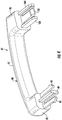
FIG. 4 is a schematic of the hand-held member ofFIG. 2 ; -
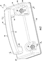
FIG. 5 is a schematic of a housing of the docking device ofFIG. 2 ; -
FIG. 6 is another schematic of the housing ofFIG. 5 ; -
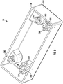
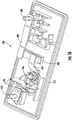
FIG. 7 is a schematic of a base plate and electrical components utilized in the docking device ofFIG. 2 ; -
FIG. 8 is another schematic of the base plate and electrical components ofFIG. 7 ; -
FIG. 9 is another schematic of the base plate and electrical components ofFIG. 7 ; -
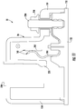
FIG. 10 is a cross-sectional schematic of the battery pack discharging device ofFIG. 2 taken along lines 10-10 inFIG. 2 ; -
FIG. 11 is a cross-sectional schematic of the docking device ofFIG. 2 when the hand-held member is not coupled to the docking device; -
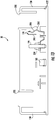
FIG. 12 is a cross-sectional schematic of the docking device ofFIG. 2 taken along lines 12-12 inFIG. 2 ; -
FIG. 13 is a cross-sectional schematic of the docking device ofFIG. 2 when the hand-held member is not coupled to the docking device; -
FIG. 14 is a cross-sectional schematic of the docking device ofFIG. 2 taken along lines 14-14 inFIG. 2 ; -
FIG. 15 is a flowchart of a method for discharging a battery pack in accordance with another exemplary embodiment; and -
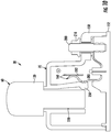
FIG. 16 is a schematic of a portion of another battery pack discharging device in accordance with another exemplary embodiment. - Referring to
FIG. 1 , anelectric vehicle 10 is illustrated. Theelectric vehicle 10 includes abattery pack 20, a batterypack discharging device 30 in accordance with an exemplary embodiment, andelectrical cables - The
battery pack 20 is provided to store and release electrical energy for the hybridelectric vehicle 10. Thebattery pack 20 includes ahousing 50,battery modules 52, apositive voltage terminal 57, and anegative voltage terminal 58. In an exemplary embodiment, thebattery pack 20 further includes a negativemain contactor 54, a positivemain contactor 55, and amain fuse 56. Thebattery modules 52 are disposed within thehousing 50. Thebattery module 52 includes a positive voltage terminal and a negative voltage terminal. The positive terminal of thebattery module 52 is electrically coupled to thepositive voltage terminal 57 of thebattery pack 20 when thepositive contactor 55 has a closed operational position andfuse 56 is installed and functional. The negative terminal of thebattery module 52 is electrically coupled to thenegative voltage terminal 58 of thebattery pack 20 when thenegative contactor 54 has a closed operational position. In one exemplary embodiment, thebattery module 52 are lithium-ion battery modules. Of course, in an alternative embodiment, thebattery module 52 could be other types of battery modules or ultra-capacitors known to those skilled in the art. Thepositive voltage terminal 57 is electrically coupled to the vehicleelectrical system 47 utilizing theelectrical cable 40, and thenegative voltage terminal 58 is electrically coupled to the vehicleelectrical system 47 utilizing theelectrical cable 42 - An advantage of the battery
pack discharging device 30 is that thedevice 30 allows an operator to electrically discharge thebattery pack 20 utilizing a single hand-heldmember 60 regardless of the status of thecontactors fuse 56. - The battery
pack discharging device 30 is provided to selectively discharge thebattery pack 20. The batterypack discharging device 30 includes a hand-heldmember 60 and adocking device 70. Thedevice 30 is electrically coupled to the positive and negative terminals of thebattery modules 52 and electrically discharges thebattery pack 20 when the hand-heldmember 60 is operably coupled to thedocking device 70. - Referring to
FIGS. 2-4 , the hand-heldmember 60 is configured to be operably coupled to thedocking device 70. In one exemplary embodiment, the hand-heldmember 60 is constructed of an electrically non-conductive material such as plastic for example. Of course, in alternative embodiments, the hand-heldmember 60 could be constructed of other electrically non-conductive materials known to those skilled in the art. The hand-heldmember 60 includes ahandle portion 80 having acentral body 81 andend portions central body 81. The hand-heldmember 60 further includes anactuation member 89 and latchingtabs end portion 82. Further, the hand-heldmember 60 includes anactuation member 104, alatching tab 102, and aguide member 100 extending from theend portion 83. - Referring to
FIGS. 1 ,2 ,4 and6 , theactuation member 89 is configured to induce the normally-open switch 160 to have a closed operational position when the hand-heldmember 60 is operably coupled to thedocking station 70 and theactuation member 89 is disposed in theaperture 220 of thehousing 140 as will be explained in greater detail below. - Referring to
FIGS. 4 and6 , the latchingtabs actuation member 89. The latchingtabs portions housing 140 of thedocking device 70 when theactuation member 89 is disposed in theaperture 220 of thehousing 140 to prevent theactuation member 89 from being removed from theaperture 220. - Referring to
FIGS. 1 ,2 ,4 and6 , theactuation member 104 is configured to induce the normally-open switch 170 to have a closed operational position when the hand-heldmember 60 is operably coupled to thedocking station 70 and theactuation member 104 is disposed in theaperture 230 of thehousing 140 as will be explained in greater detail below. - Referring to
FIGS. 4 and6 , thelatching tab 102 is disposed between theactuation member 104 and theguide member 100. Thelatching tab 102 is configured to engage a catchingportion 262 of thehousing 140 of thedocking device 70 when theactuation member 104 is disposed in theaperture 230 of thehousing 140 to prevent theactuation member 104 from being removed from theaperture 230. Theguide member 100 is configured to assist an operator to guide theactuation member 104 to a desired operational position within theaperture 230. - Referring to
FIGS. 2 ,7-9 , thedocking device 70 is configured to operably receive the hand-heldmember 60 therein. Thedocking device 70 includes ahousing 140 having ahousing portion 150 and abase plate 152. Thedocking device 70 further includesswitches resistor 180,conductive plates conductive studs electrical terminals nuts housing portion 150 and thebase plate 152 are constructed of electrically non-conductive material such as plastic for example. Of course, in alternative embodiments, thehousing portion 150 and thebase plate 152 could be constructed of other electrically non-conductive materials known to those skilled in the art. - Referring to
FIGS. 5 ,6 and10-13 , thehousing portion 150 is configured to be disposed over thebase plate 152 and the coupled to thebase plate 152. Thehousing portion 150 includesapertures aperture 220 has a first cross-sectional shape (shown inFIG. 5 ), and theaperture 230 has a second cross-sectional shape (shown inFIG. 5 ) which is different than the first cross-sectional shape. For example, in one exemplary embodiment, theaperture 220 has a plus-sign cross-sectional shape, and theaperture 230 has a minus-sign cross-sectional shape. During attachment of the hand-heldmember 60 to thedocking device 70, theactuation member 89 and the latchingtabs aperture 220 having the first cross-sectional shape. However,actuation member 89 and the latchingtabs aperture 230 having the second cross-sectional shape to contact a movable electrically non-conductive tab. Further, during attachment of the hand-heldmember 60 to thedocking device 70, theactuation member 104, thelatching tab 102, and theguide member 100 are configured to be disposed through theaperture 230 having the second cross-sectional shape. However, theactuation member 104, thelatching tab 102, and theguide member 100 cannot be disposed through theaperture 220 having the first cross-sectional shape to contact a movable electrically non-conductive tab. In an alternative embodiment, theapertures - Referring to
FIGS. 2 ,6 and7 , thehousing portion 150 further includesapertures electrical terminals - Referring to
FIG. 6 , thehousing portion 150 further includes the movable electricallynon-conductive tab 250, catchingportions non-conductive tab 260, and a catchingportion 262. - Referring to
FIGS. 4 ,6 and7 , the movable electricallynon-conductive tab 250 is disposed proximate to theaperture 220. Thetab 250 is configured to electrically isolate theswitch 160 from the hand-heldmember 60 when the hand-heldmember 60 is operably coupled to thedocking device 70. The catchingportions aperture 220 and are configured to engage the latchingtabs - Referring to
FIGS. 7 and14 , the movable electricallynon-conductive tab 260 is disposed proximate to theaperture 230. Thetab 260 is configured to electrically isolate theswitch 170 from the hand-heldmember 60 when the hand-heldmember 60 is operably coupled to thedocking device 70. The catchingportion 262 is disposed proximate to theaperture 230 and is configured to engage thelatching tab 102. - Referring to
FIGS. 7-11 , theswitch 160 is a normally-open switch. Theswitch 160 includes amovable contact member 280 and astationary contact member 282. Themovable contact member 280 and thestationary contact member 282 are disposed proximate to one another and to theaperture 220 and are coupled to thebase plate 152. Referring toFIG. 11 , themovable contact member 280 has a first operational position in which themovable contact member 280 is not physically contacting thestationary contact member 282. Referring toFIG. 10 , themovable contact member 280 has a second operational position in which themovable contact member 280 is physically contacting thestationary contact member 282 when the actuation member 89 (shown inFIG. 4 ) is disposed in the aperture 220 (shown inFIG. 6 ) such that the movable electricallynon-conductive tab 250 moves themovable contact member 280 from the first operational position to the second operational position thereof to transition theswitch 160 to the first closed operational position. - Referring to
FIGS. 7-11 , theswitch 170 is a normally-open switch. Theswitch 170 includes amovable contact member 290 and astationary contact member 292. Themovable contact member 290 and thestationary contact member 292 are disposed proximate to one another and to the aperture 230 (shown inFIG. 6 ) and are coupled to thebase plate 152. Referring toFIG. 13 , themovable contact member 290 has a first operational position in which themovable contact member 290 is not physically contacting thestationary contact member 292. Referring toFIG. 12 , themovable contact member 290 has a second operational position in which themovable contact member 290 is physically contacting thestationary contact member 292 when the actuation member 104 (shown inFIG. 4 ) is disposed in the aperture 230 (shown inFIG. 6 ) such that the movable electricallynon-conductive tab 260 moves themovable contact member 290 from the first operational position to the second operational position thereof to transition theswitch 170 to the first closed operational position. - Referring to
FIGS. 1 and7-9 , theresistor 180 is configured to dissipate electrical energy from thebattery pack 20 when theswitches resistor 180 is coupled to thebase plate 152. A first side of theresistor 180 is electrically coupled to thestationary contact member 282 utilizing theconductive plate 190. A second side of theresistor 180 is electrically coupled to thestationary contact member 292 utilizing theconductive plate 192. In an alternative embodiment, theresistor 180 could be disposed outside of thehousing 140 and could comprise a resistor bank having a plurality of resistors coupled together either in series or in parallel to one another. Further, the resistance value of theresistor 180 could be determined based on a maximum output voltage of thebattery pack 20 and a maximum desired electrical current to be received by the batterypack discharging device 30 from thebattery pack 20. In one exemplary embodiment, theconductive plates 192 are constructed of copper. - The
conductive studs base plate 152. Theconductive stud 194 extends through an aperture in theconductive plate 190 and through an aperture in thestationary contact member 282. Anut 204 is threadably disposed on an end of theconductive stud 194 to fixedly attach theconductive plate 190 to thestationary contact member 282. - The
conductive stud 196 extends through an aperture in theconductive plate 192 and an aperture in thestationary contact member 292. Anut 206 is threadably disposed on an end of theconductive stud 196 to fixedly attach theconductive plate 192 to thestationary contact member 292. - Referring to
FIGS. 2 and7-9 , theelectrical terminals base plate 152. Theelectrical terminal 200 extends through an aperture in thestationary contact member 282 and is electrically coupled to thestationary contact member 282. Theelectrical terminal 200 threadably receives anut 210 thereon for coupling theelectrical terminal 200 to the cable 40 (shown inFIG. 1 ). Theelectrical terminal 202 extends through an aperture in thestationary contact member 292 and is electrically coupled to thestationary contact member 292. Theelectrical terminal 202 threadably receives anut 212 thereon for coupling theelectrical terminal 202 to the cable 42 (shown inFIG. 1 ). - Referring to
FIGS. 1 ,2 and15 , a method for discharging thebattery pack 20 utilizing the batterypack discharging device 30 in accordance with another exemplary embodiment will now be explained. - At
step 320, thedocking device 70 is assembled onto thebattery pack 20. Thedocking device 70 has thehousing 140, switches 160, 170, and theresistor 180. Thehousing 140 hasapertures switches housing 140 proximate to theapertures switches resistor 180 is electrically coupled between theswitches switches battery pack 20. - At
step 322, the hand-heldmember 60, which has thehandle portion 80 and first andsecond actuation members handle portion 80, is stored with thebattery pack 20 and is thus made available to an operator or to emergency personnel. - At
step 324, the operator holds the hand-heldmember 60 and disposes theactuation members member 60 in theapertures housing 140 of thedocking device 70 such that theactuation members switches - At
step 326, thebattery pack 20 outputs an electrical current through theswitch 160, theresistor 180, and theswitch 170, to at least partially discharge thebattery pack 20 when theswitches - Referring to
FIG. 16 , a portion of a batterypack discharging device 430 in accordance with another exemplary embodiment is illustrated. The batterypack discharging device 430 has a similar structure as thedevice 30, except that thedevice 430 does not utilize the normally-open switch 160 and theconductive plates - In particular, the
device 430 utilizes one normally-open switch (i.e., switch 170) andconductive plates open switch 170 is electrically coupled to theelectrical terminal 202. Theswitch 170 is further coupled to a first end of theresistor 180 utilizing theconductive plate 440. A second end of theresistor 180 is electrically coupled to theelectrical terminal 200 utilizing theconductive plate 450. The device 434 further utilizes the hand-heldmember 60 discussed above, and thehousing portion 150 discussed above which is coupled to thebase plate 152. During operation, when the hand-heldmember 60 is inserted into theaperture 230, theswitch 170 is transitioned to a closed operational position in an identical manner as discussed above for thedevice 30, to discharge the battery module. - The battery pack discharging device and the method for discharging a battery pack provide a substantial advantage over other devices and methods. In particular, the battery pack discharging device and the method provide a technical effect of allowing an operator to insert a hand-held member into a docking device to discharge the battery pack, regardless of an operational state of the internal contactors and/or a fuse within the battery pack.
- While the claimed invention has been described in detail in connection with only a limited number of embodiments, it should be readily understood that the invention is not limited to such disclosed embodiments. Rather, the claimed invention can be modified to incorporate any number of variations, alterations, substitutions or equivalent arrangements not heretofore described, but which are commensurate with the scope of the invention. Additionally, while various embodiments of the claimed invention have been described, it is to be understood that aspects of the invention may include only some of the described embodiments. Accordingly, the claimed invention is not to be seen as limited by the foregoing description.
Claims (16)
- A battery pack discharging device (30) for discharging a battery pack, characterized in that it comprises:a hand-held member (60) having a handle portion (80) and first and second actuation members (89, 104) extending from the handle portion (80);a docking device (70) having a housing (140), first and second switches (160, 170), and a resistor (180), the housing (140) having first and second apertures (220, 230) extending therethrough, the first and second switches (160, 170) being disposed in the housing (140) proximate to the first and second apertures (220, 230), respectively, the first and second switches (160, 170) each having a normally-open operational position, the resistor (180) being electrically coupled to one end of the first and second switches (160, 170), the first and second switches (160, 170) further configured to be electrically coupled with their second end to the battery pack; and the first and second actuation members (89, 104) of the hand-held member (60) being configured to be introduced in the first and second apertures (220, 230), respectively, of the housing (140) of the docking device (70) thereby transitioning the first and second switches (160, 170), respectively, to first and second closed operational positions, respectively and therefore enabling the discharge of the battery pack in the resistor (180).
- The battery pack discharging device (30) of claim 1, wherein the first switch (160) comprises a first movable contact member (280) and a first stationary contact member (282), and the housing (140) has a first movable electrically non-conductive tab (250) disposed proximate to the first aperture (220).
- The battery pack discharging device (30) of claim 2, wherein the first movable contact member (280) has a first operational position in which the first movable contact member (280) is not physically contacting the first stationary contact member (282), and a second operational position in which the first movable contact member (280) is physically contacting the first stationary contact member (282), the first actuation member (89) being configured to contact the first movable electrically non-conductive tab (250) when the first actuation member (89) is disposed in the first aperture (220) such that the first movable electrically non-conductive tab (250) moves the first movable contact member (280) from the first operational position to the second operational position thereof to transition the first switch (160) to the first closed operational position.
- The battery pack discharging device (30) of claim 2, further comprising first and second latching tabs (90, 92) extending from the handle portion (80) in a first direction and being disposed proximate to first and second sides of the first actuation member (89).
- The battery pack discharging device (30) of claim 4, wherein the first and second latching tabs (90, 92) are configured to engage first and second catching portions (254, 252), respectively, of the housing (140) of the docking device (70) when the first actuation member (89) is disposed in the first aperture (220) to prevent the first actuation member (89) from being removed from the first aperture (220).
- The battery pack discharging device (30) of claim 2, wherein the second switch (170) comprises a second movable contact member (290) and a second stationary contact member (292), and the housing (140) having a second movable electrically non-conductive tab (260) disposed proximate to the second aperture (230).
- The battery pack discharging device (30) of claim 6, wherein the second movable contact member (290) having a first operational position in which the second movable contact member (290) is not physically contacting the second stationary contact member (292), and a second operational position in which the second movable contact member (290) is physically contacting the second stationary contact member (292), the second actuation member (104) being configured to contact the second movable electrically non-conductive tab (260) when the second actuation member (104) is disposed in the second aperture (230) such that the second movable electrically non-conductive tab (260) moves the second movable contact member (290) from the first operational position to the second operational position thereof to transition the second switch (170) to the second closed operational position.
- The battery pack discharging device (30) of claim 6, further comprising a first latching tab (102) extending from the handle portion (80) in a first direction and being disposed proximate to the second actuation member (104).
- The battery pack discharging device (30) of claim 8, wherein the first latching tab (102) is configured to engage a first catching portion (262) of the housing (140) of the docking device (70) when the second actuation member (104) is disposed in the second aperture (230) to prevent the second actuation member (104) from being removed from the second aperture (230).
- The battery pack discharging device (30) of claim 1, wherein the first aperture (220) has a first cross-sectional shape, and the second aperture (230) has a second cross-sectional shape, the first cross-sectional shape being different than the second cross-sectional shape.
- The battery pack discharging device (30) of claim 10, wherein the first actuation member (89) is configured to be disposed through the first aperture (220) having the first cross-sectional shape, and the first actuation member (89) cannot be disposed through the second aperture (230) having the second cross-sectional shape to contact a movable electrically non-conductive tab.
- The battery pack discharging device (30) of claim 11, wherein the second actuation member (104) is configured to be disposed through the second aperture (230) having the second cross-sectional shape, and the second actuation member (104) cannot be disposed through the first aperture (220) having the first cross-sectional shape to contact a movable electrically non-conductive tab.
- The battery pack discharging device (30) of claim 1, wherein the hand-held member (60) is constructed of an electrically non-conductive material.
- The battery pack discharging device (30) of claim 13, wherein the electrically non-conductive material is plastic.
- A method for discharging a battery pack, comprising:providing a battery pack discharging device according to one of claim 1 to 14; anddisposing the first and second actuation members of the hand-held member in the first and second apertures, respectively, of the housing of the docking device such that the first and second actuation members transition the first and second switches, respectively, to first and second closed operational positions, respectively.
- The method of claim 15, further comprising outputting an electrical current from the battery pack through the first switch, the resistor, and the second switch, to at least partially discharge the battery pack when the first and second switches have the first and second closed operational positions, respectively.
Applications Claiming Priority (2)
| Application Number | Priority Date | Filing Date | Title |
|---|---|---|---|
| US13/827,830 US8981724B2 (en) | 2013-03-14 | 2013-03-14 | Battery pack discharging device and method for discharging a battery pack |
| PCT/KR2014/002090 WO2014142563A1 (en) | 2013-03-14 | 2014-03-13 | Apparatus and method for discharging battery pack |
Publications (3)
| Publication Number | Publication Date |
|---|---|
| EP2937970A1 EP2937970A1 (en) | 2015-10-28 |
| EP2937970A4 EP2937970A4 (en) | 2016-03-09 |
| EP2937970B1 true EP2937970B1 (en) | 2017-11-29 |
Family
ID=51524682
Family Applications (1)
| Application Number | Title | Priority Date | Filing Date |
|---|---|---|---|
| EP14762480.3A Active EP2937970B1 (en) | 2013-03-14 | 2014-03-13 | Apparatus and method for discharging battery pack |
Country Status (6)
| Country | Link |
|---|---|
| US (1) | US8981724B2 (en) |
| EP (1) | EP2937970B1 (en) |
| JP (1) | JP6110510B2 (en) |
| KR (1) | KR101760496B1 (en) |
| CN (1) | CN104956561B (en) |
| WO (1) | WO2014142563A1 (en) |
Families Citing this family (8)
| Publication number | Priority date | Publication date | Assignee | Title |
|---|---|---|---|---|
| US9586489B2 (en) * | 2013-07-26 | 2017-03-07 | Lg Chem, Ltd. | Battery pack discharging device and method for discharging a battery pack |
| DE102014200262B4 (en) * | 2014-01-10 | 2025-03-13 | Robert Bosch Gmbh | Battery system with a battery that can be connected to at least one of its high-voltage terminals via a contactor, and method for switching such a contactor |
| US20200114784A1 (en) * | 2017-11-08 | 2020-04-16 | Eaton Intelligent Power Limited | System, method, and apparatus for current control in a power distribution unit |
| US11052784B2 (en) | 2017-11-08 | 2021-07-06 | Eaton Intelligent Power Limited | Power distribution unit and fuse management for an electric mobile application |
| US11070049B2 (en) | 2017-11-08 | 2021-07-20 | Eaton Intelligent Power Limited | System, method, and apparatus for power distribution in an electric mobile application using a combined breaker and relay |
| JP7073904B2 (en) * | 2018-05-21 | 2022-05-24 | 株式会社Gsユアサ | A power storage device, an external discharge device, and a discharge method using an external discharge device for the power storage device. |
| US11689010B2 (en) | 2019-02-22 | 2023-06-27 | Eaton Intelligent Power Limited | Coolant fitting promoting turbulent flow |
| CN116019516A (en) | 2020-09-16 | 2023-04-28 | 天津瑞奇外科器械股份有限公司 | Surgical instrument and battery pack thereof |
Family Cites Families (16)
| Publication number | Priority date | Publication date | Assignee | Title |
|---|---|---|---|---|
| JPH0168657U (en) * | 1987-10-27 | 1989-05-02 | ||
| JPH0674043U (en) | 1993-03-17 | 1994-10-18 | 株式会社ニコン | Secondary battery discharge adapter |
| KR200173155Y1 (en) | 1995-12-07 | 2000-03-02 | 정몽규 | Battery discharge preventing apparatus |
| US7714538B2 (en) * | 2002-11-22 | 2010-05-11 | Milwaukee Electric Tool Corporation | Battery pack |
| JP4003689B2 (en) * | 2003-04-17 | 2007-11-07 | 新神戸電機株式会社 | Battery pack for vehicles |
| ATE451731T1 (en) * | 2003-04-29 | 2009-12-15 | 3M Espe Ag | PREVENTING ELECTROCHEMICAL CORROSION ON THE CHARGING CONTACTS OF A BATTERY POWERED HANDPIECE AND ITS CHARGER |
| JP4188812B2 (en) * | 2003-12-09 | 2008-12-03 | 株式会社フジクラ | Circuit breaker |
| US20050248320A1 (en) * | 2004-05-04 | 2005-11-10 | Denning Bruce S | Switch reduction in a cordless power tool |
| KR100762086B1 (en) | 2005-01-14 | 2007-10-01 | 주식회사 엘지화학 | Apparatus and method for bucking battery |
| US20090009132A1 (en) * | 2007-07-02 | 2009-01-08 | Baruch Richard Dym | Method of powering appliances and apparatus therefor |
| KR101128423B1 (en) | 2008-04-28 | 2012-03-23 | 에스케이이노베이션 주식회사 | Safety switch of secondary battery for electric vehicle and charge / discharge system of secondary battery for electric vehicle using same |
| JP5388175B2 (en) * | 2009-01-14 | 2014-01-15 | Necエナジーデバイス株式会社 | Secondary battery pack |
| JP2011076949A (en) * | 2009-09-30 | 2011-04-14 | Toshiba Corp | Information processing apparatus |
| CN102916457B (en) * | 2011-08-05 | 2015-03-11 | 凹凸电子(武汉)有限公司 | Battery pack management system and method for balancing battery modules in battery pack |
| JP5106606B2 (en) | 2010-09-27 | 2012-12-26 | 三菱電機株式会社 | Discharge system and electric vehicle |
| JP5838056B2 (en) * | 2011-08-11 | 2015-12-24 | 富士通コンポーネント株式会社 | Switches and connectors |
-
2013
- 2013-03-14 US US13/827,830 patent/US8981724B2/en active Active
-
2014
- 2014-03-13 CN CN201480005107.3A patent/CN104956561B/en active Active
- 2014-03-13 JP JP2015549286A patent/JP6110510B2/en active Active
- 2014-03-13 EP EP14762480.3A patent/EP2937970B1/en active Active
- 2014-03-13 WO PCT/KR2014/002090 patent/WO2014142563A1/en not_active Ceased
- 2014-03-13 KR KR1020157015153A patent/KR101760496B1/en active Active
Non-Patent Citations (1)
| Title |
|---|
| None * |
Also Published As
| Publication number | Publication date |
|---|---|
| EP2937970A1 (en) | 2015-10-28 |
| JP2016507862A (en) | 2016-03-10 |
| KR101760496B1 (en) | 2017-07-21 |
| CN104956561B (en) | 2018-03-02 |
| CN104956561A (en) | 2015-09-30 |
| US20140266052A1 (en) | 2014-09-18 |
| KR20150094624A (en) | 2015-08-19 |
| EP2937970A4 (en) | 2016-03-09 |
| US8981724B2 (en) | 2015-03-17 |
| WO2014142563A1 (en) | 2014-09-18 |
| JP6110510B2 (en) | 2017-04-05 |
Similar Documents
| Publication | Publication Date | Title |
|---|---|---|
| US8981724B2 (en) | Battery pack discharging device and method for discharging a battery pack | |
| EP2505419B1 (en) | Battery disconnect unit and method of assembling the battery disconnect unit | |
| US11643033B2 (en) | Motor vehicle electrical system and vehicle with a motor vehicle electrical system | |
| EP3652833B1 (en) | Charging system | |
| US10583749B2 (en) | Battery system and method for the operation thereof | |
| US10230081B2 (en) | Voltage-protected producible motor vehicle battery | |
| JP2017508432A (en) | Battery system and method for driving battery system | |
| US9592743B2 (en) | Mobile discharge device for a battery and motor vehicle comprising a mobile discharge device | |
| EP2930771B1 (en) | Rechargeable battery | |
| CN108602438A (en) | The method of high-voltage electric system and operation high-voltage electric system with pyrotechnics isolating device | |
| KR20150057732A (en) | Protection apparutus for rechargeable battery | |
| WO2015078049A1 (en) | A connection device and method for vehicle | |
| JP2014180185A (en) | Battery module | |
| CN104025369A (en) | Battery system and motor vehicle | |
| US11309151B2 (en) | Direct current electric circuit interrupting switch assembly | |
| US9160163B2 (en) | Battery management system, motor vehicle and battery system | |
| EP4080674B1 (en) | Battery module | |
| US10637036B2 (en) | Method for manufacturing a battery, battery, and motor vehicle | |
| EP2999081B1 (en) | Battery pack discharging device and battery pack discharging method | |
| CN104810500A (en) | Current interruption device for traction battery pack | |
| CN103682504A (en) | Battery and motor vehicle |
Legal Events
| Date | Code | Title | Description |
|---|---|---|---|
| PUAI | Public reference made under article 153(3) epc to a published international application that has entered the european phase |
Free format text: ORIGINAL CODE: 0009012 |
|
| 17P | Request for examination filed |
Effective date: 20150717 |
|
| AK | Designated contracting states |
Kind code of ref document: A1 Designated state(s): AL AT BE BG CH CY CZ DE DK EE ES FI FR GB GR HR HU IE IS IT LI LT LU LV MC MK MT NL NO PL PT RO RS SE SI SK SM TR |
|
| AX | Request for extension of the european patent |
Extension state: BA ME |
|
| A4 | Supplementary search report drawn up and despatched |
Effective date: 20160205 |
|
| RIC1 | Information provided on ipc code assigned before grant |
Ipc: B60L 11/18 20060101ALI20160201BHEP Ipc: H01M 10/44 20060101ALI20160201BHEP Ipc: H02J 7/00 20060101AFI20160201BHEP Ipc: B60W 10/26 20060101ALI20160201BHEP Ipc: B60L 3/04 20060101ALI20160201BHEP |
|
| DAX | Request for extension of the european patent (deleted) | ||
| 17Q | First examination report despatched |
Effective date: 20160912 |
|
| STAA | Information on the status of an ep patent application or granted ep patent |
Free format text: STATUS: EXAMINATION IS IN PROGRESS |
|
| GRAP | Despatch of communication of intention to grant a patent |
Free format text: ORIGINAL CODE: EPIDOSNIGR1 |
|
| STAA | Information on the status of an ep patent application or granted ep patent |
Free format text: STATUS: GRANT OF PATENT IS INTENDED |
|
| INTG | Intention to grant announced |
Effective date: 20170413 |
|
| GRAS | Grant fee paid |
Free format text: ORIGINAL CODE: EPIDOSNIGR3 |
|
| GRAJ | Information related to disapproval of communication of intention to grant by the applicant or resumption of examination proceedings by the epo deleted |
Free format text: ORIGINAL CODE: EPIDOSDIGR1 |
|
| GRAL | Information related to payment of fee for publishing/printing deleted |
Free format text: ORIGINAL CODE: EPIDOSDIGR3 |
|
| STAA | Information on the status of an ep patent application or granted ep patent |
Free format text: STATUS: EXAMINATION IS IN PROGRESS |
|
| INTC | Intention to grant announced (deleted) | ||
| GRAP | Despatch of communication of intention to grant a patent |
Free format text: ORIGINAL CODE: EPIDOSNIGR1 |
|
| STAA | Information on the status of an ep patent application or granted ep patent |
Free format text: STATUS: GRANT OF PATENT IS INTENDED |
|
| GRAA | (expected) grant |
Free format text: ORIGINAL CODE: 0009210 |
|
| STAA | Information on the status of an ep patent application or granted ep patent |
Free format text: STATUS: THE PATENT HAS BEEN GRANTED |
|
| INTG | Intention to grant announced |
Effective date: 20171016 |
|
| AK | Designated contracting states |
Kind code of ref document: B1 Designated state(s): AL AT BE BG CH CY CZ DE DK EE ES FI FR GB GR HR HU IE IS IT LI LT LU LV MC MK MT NL NO PL PT RO RS SE SI SK SM TR |
|
| REG | Reference to a national code |
Ref country code: CH Ref legal event code: EP |
|
| REG | Reference to a national code |
Ref country code: AT Ref legal event code: REF Ref document number: 951241 Country of ref document: AT Kind code of ref document: T Effective date: 20171215 |
|
| REG | Reference to a national code |
Ref country code: IE Ref legal event code: FG4D |
|
| REG | Reference to a national code |
Ref country code: DE Ref legal event code: R096 Ref document number: 602014017942 Country of ref document: DE |
|
| REG | Reference to a national code |
Ref country code: FR Ref legal event code: PLFP Year of fee payment: 5 |
|
| REG | Reference to a national code |
Ref country code: NL Ref legal event code: MP Effective date: 20171129 |
|
| REG | Reference to a national code |
Ref country code: LT Ref legal event code: MG4D |
|
| REG | Reference to a national code |
Ref country code: AT Ref legal event code: MK05 Ref document number: 951241 Country of ref document: AT Kind code of ref document: T Effective date: 20171129 |
|
| PG25 | Lapsed in a contracting state [announced via postgrant information from national office to epo] |
Ref country code: NO Free format text: LAPSE BECAUSE OF FAILURE TO SUBMIT A TRANSLATION OF THE DESCRIPTION OR TO PAY THE FEE WITHIN THE PRESCRIBED TIME-LIMIT Effective date: 20180228 Ref country code: SE Free format text: LAPSE BECAUSE OF FAILURE TO SUBMIT A TRANSLATION OF THE DESCRIPTION OR TO PAY THE FEE WITHIN THE PRESCRIBED TIME-LIMIT Effective date: 20171129 Ref country code: LT Free format text: LAPSE BECAUSE OF FAILURE TO SUBMIT A TRANSLATION OF THE DESCRIPTION OR TO PAY THE FEE WITHIN THE PRESCRIBED TIME-LIMIT Effective date: 20171129 Ref country code: FI Free format text: LAPSE BECAUSE OF FAILURE TO SUBMIT A TRANSLATION OF THE DESCRIPTION OR TO PAY THE FEE WITHIN THE PRESCRIBED TIME-LIMIT Effective date: 20171129 Ref country code: ES Free format text: LAPSE BECAUSE OF FAILURE TO SUBMIT A TRANSLATION OF THE DESCRIPTION OR TO PAY THE FEE WITHIN THE PRESCRIBED TIME-LIMIT Effective date: 20171129 |
|
| PG25 | Lapsed in a contracting state [announced via postgrant information from national office to epo] |
Ref country code: LV Free format text: LAPSE BECAUSE OF FAILURE TO SUBMIT A TRANSLATION OF THE DESCRIPTION OR TO PAY THE FEE WITHIN THE PRESCRIBED TIME-LIMIT Effective date: 20171129 Ref country code: BG Free format text: LAPSE BECAUSE OF FAILURE TO SUBMIT A TRANSLATION OF THE DESCRIPTION OR TO PAY THE FEE WITHIN THE PRESCRIBED TIME-LIMIT Effective date: 20180228 Ref country code: HR Free format text: LAPSE BECAUSE OF FAILURE TO SUBMIT A TRANSLATION OF THE DESCRIPTION OR TO PAY THE FEE WITHIN THE PRESCRIBED TIME-LIMIT Effective date: 20171129 Ref country code: GR Free format text: LAPSE BECAUSE OF FAILURE TO SUBMIT A TRANSLATION OF THE DESCRIPTION OR TO PAY THE FEE WITHIN THE PRESCRIBED TIME-LIMIT Effective date: 20180301 Ref country code: AT Free format text: LAPSE BECAUSE OF FAILURE TO SUBMIT A TRANSLATION OF THE DESCRIPTION OR TO PAY THE FEE WITHIN THE PRESCRIBED TIME-LIMIT Effective date: 20171129 Ref country code: RS Free format text: LAPSE BECAUSE OF FAILURE TO SUBMIT A TRANSLATION OF THE DESCRIPTION OR TO PAY THE FEE WITHIN THE PRESCRIBED TIME-LIMIT Effective date: 20171129 |
|
| PG25 | Lapsed in a contracting state [announced via postgrant information from national office to epo] |
Ref country code: NL Free format text: LAPSE BECAUSE OF FAILURE TO SUBMIT A TRANSLATION OF THE DESCRIPTION OR TO PAY THE FEE WITHIN THE PRESCRIBED TIME-LIMIT Effective date: 20171129 |
|
| PG25 | Lapsed in a contracting state [announced via postgrant information from national office to epo] |
Ref country code: CZ Free format text: LAPSE BECAUSE OF FAILURE TO SUBMIT A TRANSLATION OF THE DESCRIPTION OR TO PAY THE FEE WITHIN THE PRESCRIBED TIME-LIMIT Effective date: 20171129 Ref country code: SK Free format text: LAPSE BECAUSE OF FAILURE TO SUBMIT A TRANSLATION OF THE DESCRIPTION OR TO PAY THE FEE WITHIN THE PRESCRIBED TIME-LIMIT Effective date: 20171129 Ref country code: EE Free format text: LAPSE BECAUSE OF FAILURE TO SUBMIT A TRANSLATION OF THE DESCRIPTION OR TO PAY THE FEE WITHIN THE PRESCRIBED TIME-LIMIT Effective date: 20171129 Ref country code: DK Free format text: LAPSE BECAUSE OF FAILURE TO SUBMIT A TRANSLATION OF THE DESCRIPTION OR TO PAY THE FEE WITHIN THE PRESCRIBED TIME-LIMIT Effective date: 20171129 Ref country code: CY Free format text: LAPSE BECAUSE OF FAILURE TO SUBMIT A TRANSLATION OF THE DESCRIPTION OR TO PAY THE FEE WITHIN THE PRESCRIBED TIME-LIMIT Effective date: 20171129 |
|
| REG | Reference to a national code |
Ref country code: DE Ref legal event code: R097 Ref document number: 602014017942 Country of ref document: DE |
|
| PG25 | Lapsed in a contracting state [announced via postgrant information from national office to epo] |
Ref country code: RO Free format text: LAPSE BECAUSE OF FAILURE TO SUBMIT A TRANSLATION OF THE DESCRIPTION OR TO PAY THE FEE WITHIN THE PRESCRIBED TIME-LIMIT Effective date: 20171129 Ref country code: IT Free format text: LAPSE BECAUSE OF FAILURE TO SUBMIT A TRANSLATION OF THE DESCRIPTION OR TO PAY THE FEE WITHIN THE PRESCRIBED TIME-LIMIT Effective date: 20171129 Ref country code: SM Free format text: LAPSE BECAUSE OF FAILURE TO SUBMIT A TRANSLATION OF THE DESCRIPTION OR TO PAY THE FEE WITHIN THE PRESCRIBED TIME-LIMIT Effective date: 20171129 Ref country code: PL Free format text: LAPSE BECAUSE OF FAILURE TO SUBMIT A TRANSLATION OF THE DESCRIPTION OR TO PAY THE FEE WITHIN THE PRESCRIBED TIME-LIMIT Effective date: 20171129 |
|
| PLBE | No opposition filed within time limit |
Free format text: ORIGINAL CODE: 0009261 |
|
| STAA | Information on the status of an ep patent application or granted ep patent |
Free format text: STATUS: NO OPPOSITION FILED WITHIN TIME LIMIT |
|
| REG | Reference to a national code |
Ref country code: CH Ref legal event code: PL |
|
| 26N | No opposition filed |
Effective date: 20180830 |
|
| PG25 | Lapsed in a contracting state [announced via postgrant information from national office to epo] |
Ref country code: MC Free format text: LAPSE BECAUSE OF FAILURE TO SUBMIT A TRANSLATION OF THE DESCRIPTION OR TO PAY THE FEE WITHIN THE PRESCRIBED TIME-LIMIT Effective date: 20171129 Ref country code: SI Free format text: LAPSE BECAUSE OF FAILURE TO SUBMIT A TRANSLATION OF THE DESCRIPTION OR TO PAY THE FEE WITHIN THE PRESCRIBED TIME-LIMIT Effective date: 20171129 |
|
| REG | Reference to a national code |
Ref country code: BE Ref legal event code: MM Effective date: 20180331 |
|
| REG | Reference to a national code |
Ref country code: IE Ref legal event code: MM4A |
|
| PG25 | Lapsed in a contracting state [announced via postgrant information from national office to epo] |
Ref country code: LU Free format text: LAPSE BECAUSE OF NON-PAYMENT OF DUE FEES Effective date: 20180313 |
|
| PG25 | Lapsed in a contracting state [announced via postgrant information from national office to epo] |
Ref country code: IE Free format text: LAPSE BECAUSE OF NON-PAYMENT OF DUE FEES Effective date: 20180313 |
|
| PG25 | Lapsed in a contracting state [announced via postgrant information from national office to epo] |
Ref country code: CH Free format text: LAPSE BECAUSE OF NON-PAYMENT OF DUE FEES Effective date: 20180331 Ref country code: LI Free format text: LAPSE BECAUSE OF NON-PAYMENT OF DUE FEES Effective date: 20180331 Ref country code: BE Free format text: LAPSE BECAUSE OF NON-PAYMENT OF DUE FEES Effective date: 20180331 |
|
| PG25 | Lapsed in a contracting state [announced via postgrant information from national office to epo] |
Ref country code: MT Free format text: LAPSE BECAUSE OF NON-PAYMENT OF DUE FEES Effective date: 20180313 |
|
| PG25 | Lapsed in a contracting state [announced via postgrant information from national office to epo] |
Ref country code: TR Free format text: LAPSE BECAUSE OF FAILURE TO SUBMIT A TRANSLATION OF THE DESCRIPTION OR TO PAY THE FEE WITHIN THE PRESCRIBED TIME-LIMIT Effective date: 20171129 |
|
| PG25 | Lapsed in a contracting state [announced via postgrant information from national office to epo] |
Ref country code: PT Free format text: LAPSE BECAUSE OF FAILURE TO SUBMIT A TRANSLATION OF THE DESCRIPTION OR TO PAY THE FEE WITHIN THE PRESCRIBED TIME-LIMIT Effective date: 20171129 |
|
| PG25 | Lapsed in a contracting state [announced via postgrant information from national office to epo] |
Ref country code: HU Free format text: LAPSE BECAUSE OF FAILURE TO SUBMIT A TRANSLATION OF THE DESCRIPTION OR TO PAY THE FEE WITHIN THE PRESCRIBED TIME-LIMIT; INVALID AB INITIO Effective date: 20140313 Ref country code: MK Free format text: LAPSE BECAUSE OF NON-PAYMENT OF DUE FEES Effective date: 20171129 |
|
| PG25 | Lapsed in a contracting state [announced via postgrant information from national office to epo] |
Ref country code: AL Free format text: LAPSE BECAUSE OF FAILURE TO SUBMIT A TRANSLATION OF THE DESCRIPTION OR TO PAY THE FEE WITHIN THE PRESCRIBED TIME-LIMIT Effective date: 20171129 Ref country code: IS Free format text: LAPSE BECAUSE OF FAILURE TO SUBMIT A TRANSLATION OF THE DESCRIPTION OR TO PAY THE FEE WITHIN THE PRESCRIBED TIME-LIMIT Effective date: 20180329 |
|
| P01 | Opt-out of the competence of the unified patent court (upc) registered |
Effective date: 20230512 |
|
| REG | Reference to a national code |
Ref country code: DE Ref legal event code: R081 Ref document number: 602014017942 Country of ref document: DE Owner name: LG ENERGY SOLUTION, LTD., KR Free format text: FORMER OWNER: LG CHEM, LTD., SEOUL, KR |
|
| REG | Reference to a national code |
Ref country code: GB Ref legal event code: 732E Free format text: REGISTERED BETWEEN 20230824 AND 20230831 |
|
| PGFP | Annual fee paid to national office [announced via postgrant information from national office to epo] |
Ref country code: GB Payment date: 20260224 Year of fee payment: 13 |
|
| PGFP | Annual fee paid to national office [announced via postgrant information from national office to epo] |
Ref country code: DE Payment date: 20260220 Year of fee payment: 13 |
|
| PGFP | Annual fee paid to national office [announced via postgrant information from national office to epo] |
Ref country code: FR Payment date: 20260224 Year of fee payment: 13 |