EP2937710A1 - Method and kinematic calibration system for measuring displacements and vibrations of objects/structures - Google Patents
Method and kinematic calibration system for measuring displacements and vibrations of objects/structures Download PDFInfo
- Publication number
- EP2937710A1 EP2937710A1 EP15164873.0A EP15164873A EP2937710A1 EP 2937710 A1 EP2937710 A1 EP 2937710A1 EP 15164873 A EP15164873 A EP 15164873A EP 2937710 A1 EP2937710 A1 EP 2937710A1
- Authority
- EP
- European Patent Office
- Prior art keywords
- radar
- receiver
- calibration
- interfering signals
- signal
- Prior art date
- Legal status (The legal status is an assumption and is not a legal conclusion. Google has not performed a legal analysis and makes no representation as to the accuracy of the status listed.)
- Granted
Links
Images



Classifications
-
- G—PHYSICS
- G01—MEASURING; TESTING
- G01S—RADIO DIRECTION-FINDING; RADIO NAVIGATION; DETERMINING DISTANCE OR VELOCITY BY USE OF RADIO WAVES; LOCATING OR PRESENCE-DETECTING BY USE OF THE REFLECTION OR RERADIATION OF RADIO WAVES; ANALOGOUS ARRANGEMENTS USING OTHER WAVES
- G01S7/00—Details of systems according to groups G01S13/00, G01S15/00, G01S17/00
- G01S7/02—Details of systems according to groups G01S13/00, G01S15/00, G01S17/00 of systems according to group G01S13/00
- G01S7/40—Means for monitoring or calibrating
- G01S7/4052—Means for monitoring or calibrating by simulation of echoes
- G01S7/4082—Means for monitoring or calibrating by simulation of echoes using externally generated reference signals, e.g. via remote reflector or transponder
- G01S7/4095—Means for monitoring or calibrating by simulation of echoes using externally generated reference signals, e.g. via remote reflector or transponder the external reference signals being modulated, e.g. rotating a dihedral reflector or modulating a transponder for simulation of a Doppler echo
-
- G—PHYSICS
- G01—MEASURING; TESTING
- G01H—MEASUREMENT OF MECHANICAL VIBRATIONS OR ULTRASONIC, SONIC OR INFRASONIC WAVES
- G01H9/00—Measuring mechanical vibrations or ultrasonic, sonic or infrasonic waves by using radiation-sensitive means, e.g. optical means
-
- G—PHYSICS
- G01—MEASURING; TESTING
- G01S—RADIO DIRECTION-FINDING; RADIO NAVIGATION; DETERMINING DISTANCE OR VELOCITY BY USE OF RADIO WAVES; LOCATING OR PRESENCE-DETECTING BY USE OF THE REFLECTION OR RERADIATION OF RADIO WAVES; ANALOGOUS ARRANGEMENTS USING OTHER WAVES
- G01S13/00—Systems using the reflection or reradiation of radio waves, e.g. radar systems; Analogous systems using reflection or reradiation of waves whose nature or wavelength is irrelevant or unspecified
- G01S13/02—Systems using reflection of radio waves, e.g. primary radar systems; Analogous systems
- G01S13/06—Systems determining position data of a target
- G01S13/08—Systems for measuring distance only
-
- G—PHYSICS
- G01—MEASURING; TESTING
- G01S—RADIO DIRECTION-FINDING; RADIO NAVIGATION; DETERMINING DISTANCE OR VELOCITY BY USE OF RADIO WAVES; LOCATING OR PRESENCE-DETECTING BY USE OF THE REFLECTION OR RERADIATION OF RADIO WAVES; ANALOGOUS ARRANGEMENTS USING OTHER WAVES
- G01S13/00—Systems using the reflection or reradiation of radio waves, e.g. radar systems; Analogous systems using reflection or reradiation of waves whose nature or wavelength is irrelevant or unspecified
- G01S13/02—Systems using reflection of radio waves, e.g. primary radar systems; Analogous systems
- G01S13/50—Systems of measurement based on relative movement of target
- G01S13/58—Velocity or trajectory determination systems; Sense-of-movement determination systems
-
- G—PHYSICS
- G01—MEASURING; TESTING
- G01S—RADIO DIRECTION-FINDING; RADIO NAVIGATION; DETERMINING DISTANCE OR VELOCITY BY USE OF RADIO WAVES; LOCATING OR PRESENCE-DETECTING BY USE OF THE REFLECTION OR RERADIATION OF RADIO WAVES; ANALOGOUS ARRANGEMENTS USING OTHER WAVES
- G01S7/00—Details of systems according to groups G01S13/00, G01S15/00, G01S17/00
- G01S7/02—Details of systems according to groups G01S13/00, G01S15/00, G01S17/00 of systems according to group G01S13/00
- G01S7/35—Details of non-pulse systems
- G01S7/352—Receivers
- G01S7/354—Extracting wanted echo-signals
-
- G—PHYSICS
- G01—MEASURING; TESTING
- G01S—RADIO DIRECTION-FINDING; RADIO NAVIGATION; DETERMINING DISTANCE OR VELOCITY BY USE OF RADIO WAVES; LOCATING OR PRESENCE-DETECTING BY USE OF THE REFLECTION OR RERADIATION OF RADIO WAVES; ANALOGOUS ARRANGEMENTS USING OTHER WAVES
- G01S7/00—Details of systems according to groups G01S13/00, G01S15/00, G01S17/00
- G01S7/02—Details of systems according to groups G01S13/00, G01S15/00, G01S17/00 of systems according to group G01S13/00
- G01S7/40—Means for monitoring or calibrating
-
- G—PHYSICS
- G01—MEASURING; TESTING
- G01S—RADIO DIRECTION-FINDING; RADIO NAVIGATION; DETERMINING DISTANCE OR VELOCITY BY USE OF RADIO WAVES; LOCATING OR PRESENCE-DETECTING BY USE OF THE REFLECTION OR RERADIATION OF RADIO WAVES; ANALOGOUS ARRANGEMENTS USING OTHER WAVES
- G01S7/00—Details of systems according to groups G01S13/00, G01S15/00, G01S17/00
- G01S7/02—Details of systems according to groups G01S13/00, G01S15/00, G01S17/00 of systems according to group G01S13/00
- G01S7/40—Means for monitoring or calibrating
- G01S7/4052—Means for monitoring or calibrating by simulation of echoes
Definitions
- the present invention relates to a method and a kinematic calibration system for measuring displacements and vibrations of objects/structures, in particular a method and a system which use a radar interferometry technique which provides, in real time, an estimation of the displacements, deformations and vibrations of objects/structures using simultaneous measurements effected by one or more radar devices positioned in one or more corresponding remote points with respect to the object/structure, consequently without requiring the installation of measurement and/or electrical equipment placed in direct contact with the object/structure to be measured.
- the method and system according to the invention provide measurements of displacements and vibrations with a micrometric accuracy and sensitivity and with response times in the order of milliseconds.
- Possible application fields of this method and system relate to petrochemical installations, for example, gas compression stations, thermal power plants, dams and forced ducts, refineries, offshore platforms, wind turbines, bridges and viaducts, monuments, historical buildings, etc.
- the antenna limits the "visibility" of the radar to an extremely narrow angle range around the target P.
- ⁇ is the radar wavelength.
- the angular aperture must be equal to ⁇ « 1/50 rad, and therefore the length must be equal to L >> 50 ⁇ .
- a drawback of the system with directional radar antennas is due to the dimension/encumbrance of the radar system (various meters) which can become critical, in addition to the cost, weight, etc..
- SAR systems attenuate the problem of the angular aperture by using a synthetic antenna, or by moving a radar in multiple positions, effecting a measurement for each position and then recombining the measurements by means of numerical processing of the signals.
- These systems do not solve the problem of encumbrance (the total aperture does not change) and also require a much longer time for effecting the displacement/vibration measurement, reducing the revisiting time of the scenario.
- equation (1) is valid in the hypothesis of a "far field" i.e. for targets positioned at much greater distances than the Fraunhofer distance d r : d r > > 2 ⁇ L 2 ⁇ which, in the example indicated above (L >> 50 ⁇ ) would lead to a distance d r in the order of hundreds of meters. For shorter distances, there is no desired separation of the interfering contributions.
- the movement extension must be significantly greater than the wavelength ⁇ and is therefore in the order of various centimetres. Consequently, not even are these techniques suitable for measuring displacements and vibrations of a small entity.
- the objective of the present invention is therefore to provide a method and a kinematic calibration system for measuring displacements and vibrations of objects /structures, in particular a method and system which use a radar interferometry technique, capable of solving the drawbacks of the known art indicated above in an extremely simple, economical and particularly functional manner.
- the method and kinematic calibration system for measuring displacements and vibrations of objects/structures allow the contribution of the vibrational motion of a certain target of interest to be separated from that of one or more further stationary or almost stationary targets.
- This separation phase is obtained by inducing, in the target of interest, a known vibrational motion, for example repetitive, and sufficiently extensive as to be separated from the contributions of the further almost stationary targets.
- the contribution of the interfering targets can be estimated and is then removed, eliminating the interference itself. This removal is effected once the vibration intentionally induced in the target, which has a limited duration, has been deactivated.
- the characterizing aspect relates to the whole kinematic calibration procedure, including both the vibrating target (actuator-shaker), and the processing suitable for estimating and cancelling the interfering contribution in the measurement scenario. It is important to note that the radar measurement system functions if the interfering target or targets move very slowly, so that this motion can be reconstructed by measurements at periodic intervals.
- these show a method and kinematic calibration system for measuring displacements and vibrations of objects/structures according to the present invention, in particular a method and system which use a radar interferometry technique.
- the precise estimation of the position and displacement of an item/structure (indicated with P) using a single radar device (indicated with Q) with the interferometric technique exploits a knowledge of the reflection phase of the radar waves (having removed the ambiguity of multiples of 2n) for determining the "LOS" (acronym of "line of sight” ) distance R LOs (t) between the radar device Q and the item/structure P:
- R LOS t - ⁇ t 4 ⁇ ⁇ ⁇ ⁇
- ⁇ is the phase of the received signal, after demodulation.
- the measurement of the phase ⁇ allows the variation in the distance R LOS (t) between the radar device Q and the item/structure P, to be known, in multiple time ranges of the repetition period T, as per equation 4.
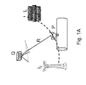
- This measurement of the phase ⁇ can be altered by the presence of various interfering targets I 1 , I 2 positioned at the same distance from the radar device Q or, in other words, within the resolution of the same radar device Q, with respect to the object /structure P, as shown in figure 1A .
- Figure 1A shows two interfering targets I 1 , I 2 positioned at the same distance, and therefore isochronous, with respect to the object/structure P, or "useful" target.
- the radar device Q is a linear system
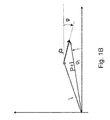
- the result of the interference is given by the sum of the contribution of the object /structure P, represented as a vector in figure 1B
- the interfering contribution I represented with a different vector in the same figure 1B .
- the amplitudes of the vectors P and I are proportional to the reflectivity, or "radar cross section", of the object /structure P and interfering targets I 1 , I 2 respectively, in the measurement field.
- phase of the vector P forms the useful signal ⁇
- phase of the interfering vector I is not generally known, depending on the position, amplitude and reflection coefficient of all the targets I n forming the interference.
- the result of the measurement is the phase of the sum P + I of the two contributions, i.e. ⁇ t , that can differ considerably from the contribution ⁇ to be measured, depending on the amplitudes of P and I, as shown in figure 1B .
- the estimation of the interfering contribution i.e. A I e j ⁇ I
- a I e j ⁇ I is effected by means of a statistical technique based on a knowledge of the phase term ⁇ P (t) due to the vibrational movement induced in equation (5).
- An example of the two contributions A P e j ⁇ P ( t ) e A I e j ⁇ I of equation (5) is shown in the range-frequency graph of figure 5 , which indicates the Fourier transform of the demodulated complex radar signal s(t) in different range positions.
- the calibration phase is repeated periodically, as indicated in figure 3 , for updating the estimation of the interfering contribution I with respect to possible changes in the interference (slow movements, amplitudes, etc.).
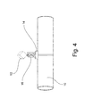
- the kinematic calibration device according to the invention is represented in figure 4 .
- Said calibration device consists of:
- the vibration mechanism 16 can be mechanically activated or powered by batteries, as for systems used in mobile phones, and must be periodically activated and deactivated. When the vibration mechanism 16 is deactivated, the reflector element 12 moves integrally with the object /structure P. The mechanism 16 is produced so as to periodically repeat the same vibration, with a better precision than the wavelength.
- the vibration mechanism 16 can operate according to different modes.
- An example of a vibration can consist in a sinusoidal motion generated by the vibration mechanism 16 by a battery motor and a cam.
- the adapted filter is represented by the Fourier transform.
- Figure 5 shows the module of said Fourier transform, measured for each possible distance ("range") between target and radar system. It can be immediately observed that this result allows the contribution of the vibrating target, that can be identified at a distance of about 12 m and a frequency of 6 Hz, to be separated with respect to all the other contributions.
- the complex amplitude of the target measured in correspondence with the peak (6 Hz and 12 m), provides the estimation of the complex contribution P of figure 1B .
- the estimation of the vector I is given by the complex contribution P measured at null frequency.
- a further example of application of the method according to the invention was effected by equipping a vibration actuator (shaker) having wide-range frequencies with a target visible to the radar system, in order to verify the sensitivity of the same radar system to the variation in frequency and therefore to effectively and accurately calibrate the receiving and calibration device 10.
- a vibration actuator (shaker) having wide-range frequencies with a target visible to the radar system
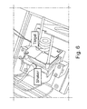
- FIG. 6 shows an example of a verification system of the performances of the calibration method according to the invention.
- the verification system effects an estimation of the vibration of a target assembled on a precision actuator (shaker) for measurement tests of the vibrations with a variation in the "sweep frequency".
- figures 7A and 7B show the results of radar estimations of two known vibrations equal to 90 Hz and 590 Hz with respect to a reference accelerometer.
- the optimum vibration frequency of the calibration target, object of the method according to the invention can be accurately determined thanks to the measurements indicated.
Landscapes
- Engineering & Computer Science (AREA)
- Radar, Positioning & Navigation (AREA)
- Remote Sensing (AREA)
- Physics & Mathematics (AREA)
- General Physics & Mathematics (AREA)
- Computer Networks & Wireless Communication (AREA)
- Radar Systems Or Details Thereof (AREA)
- Measurement Of Mechanical Vibrations Or Ultrasonic Waves (AREA)
- Measurement Of Velocity Or Position Using Acoustic Or Ultrasonic Waves (AREA)
Abstract
Description
- The present invention relates to a method and a kinematic calibration system for measuring displacements and vibrations of objects/structures, in particular a method and a system which use a radar interferometry technique which provides, in real time, an estimation of the displacements, deformations and vibrations of objects/structures using simultaneous measurements effected by one or more radar devices positioned in one or more corresponding remote points with respect to the object/structure, consequently without requiring the installation of measurement and/or electrical equipment placed in direct contact with the object/structure to be measured.
- The method and system according to the invention provide measurements of displacements and vibrations with a micrometric accuracy and sensitivity and with response times in the order of milliseconds. Possible application fields of this method and system relate to petrochemical installations, for example, gas compression stations, thermal power plants, dams and forced ducts, refineries, offshore platforms, wind turbines, bridges and viaducts, monuments, historical buildings, etc.
- Among the radar-type systems currently used for measuring displacements of objects/structures, the following can be mentioned:
- synthetic-aperture radar systems, such as that described, for example, in the document
US 2011/0298655 A1 . These systems, called "SAR" (acronym of Synthetic Aperture Radar), are capable of separating contributions in space by synthesis of a radar antenna having considerable dimensions. This synthesis is obtained by moving the radar sensor on a slide or with other devices, among which, for example, aeroplanes and satellites in the case of considerable distances. They are therefore cumbersome and costly devices which also require considerable time (from seconds to minutes) for every measurement acquisition, thus reducing the revisiting duration of the target, i.e. the object to be measured; - "active" systems (such as transponders) of the type described, for example, in the document
EP 2382487 A1 . These systems solve the problem of interference, using different codes and/or frequencies for each device, similar to what is used in the telecommunications industry for mobile systems. The functioning principle can be attributed to that of secondary radars for aeronautical use. The limits in the use of these systems are due to the fact that they are active and must therefore be installed in direct contact with the object/structure to be measured. These systems also emit electromagnetic fields and have a limited stability over long periods of time due to thermal drifts and aging; - simultaneous optical/radar measurement systems of the type described, for example, in the document
US 2006/0260407 A1 , provided with one or two receiver devices for eliminating errors in the vibration field. These systems, however, do not solve the problem of interference; - inverse "SAR" radar (or "ISAR") systems of the type described, for example, in the document
EP 1178330 A1 , which mediate on relatively lengthy times, displacements comparable to a wavelength. Inverse SAR systems exploit a significant displacement of the target in an "across range" direction for distinguishing it from possible interferences. This leads to effective applications in a military or automobile context, but is of no interest for assessing vibrations, in which the target composed of the object/structure to be measured, substantially maintains the same position; - space-time "STAP" signal processing systems (Melvin, W.L., "A STAP overview", Aerospace and Electronic Systems Magazine, IEEE, vol. 19, no. 1, pages 19-35, Jan. 2004; Ender, J., "Space-time processing for multichannel synthetic aperture radar", Electronics & Communication Engineering Journal, Feb. 1999). Also in this case, it is assumed that the movement of the target extends for numerous wavelengths, i.e. for many centimetres.
- The technical problem inherent in the simultaneous interferometric radar measurement of displacements and vibrations of numerous targets is generally the impossibility of the radar system of distinguishing reflected signals ("echoes") coming from targets localized at the same distance. This condition is illustrated, for example, in
figure 1A of the enclosed drawings, in which the echoes of the target P, which is the object/structure whose displacement is to be measured, are isochronous with respect to those of the interfering targets I1,I2 positioned at the same distance from the radar device Q. The overlapping of the three reflected signals creates an interference which prevents a correct measurement of the displacement of the target P. An example of the effect of this interference is shown infigure 1B in which the movement of the target P, for example of the sinusoidal type, is distorted and attenuated in amplitude. - Methods and systems according to the known art, as indicated above, separate the various contributions, which are based on two distinct principles:
- by means of directional radar antennas;
- by the space-time processing of the signals.
- In the case of directional radar antennas, the antenna limits the "visibility" of the radar to an extremely narrow angle range around the target P. An antenna having a length L has an angular aperture Δψ correlated to the diffraction principle:

- "SAR" systems attenuate the problem of the angular aperture by using a synthetic antenna, or by moving a radar in multiple positions, effecting a measurement for each position and then recombining the measurements by means of numerical processing of the signals. These systems, however, do not solve the problem of encumbrance (the total aperture does not change) and also require a much longer time for effecting the displacement/vibration measurement, reducing the revisiting time of the scenario.
- Furthermore, it can be observed that equation (1) is valid in the hypothesis of a "far field" i.e. for targets positioned at much greater distances than the Fraunhofer distance dr:

- In the case of systems that fall within the condition expressed by equation (2), a space-time processing of the radar signals is exploited for distinguishing a moving target with respect to a stationary or almost stationary target. In this condition, inverse radar systems "ISAR" which use the motion of the target to form a synthetic aperture are also considered. These latter systems require a predominant linear motion characteristic, i.e. a significant displacement of the target, and they are not suitable for vibrational motions (typically harmonic).
- Also in the case of time processing such as "MTI" (acronym of "moving target indicator") techniques, the movement extension must be significantly greater than the wavelength λ and is therefore in the order of various centimetres. Consequently, not even are these techniques suitable for measuring displacements and vibrations of a small entity.
- The objective of the present invention is therefore to provide a method and a kinematic calibration system for measuring displacements and vibrations of objects /structures, in particular a method and system which use a radar interferometry technique, capable of solving the drawbacks of the known art indicated above in an extremely simple, economical and particularly functional manner.
- The method and kinematic calibration system for measuring displacements and vibrations of objects/structures according to the present invention allow the contribution of the vibrational motion of a certain target of interest to be separated from that of one or more further stationary or almost stationary targets. This separation phase is obtained by inducing, in the target of interest, a known vibrational motion, for example repetitive, and sufficiently extensive as to be separated from the contributions of the further almost stationary targets.
- With a suitable processing of the radar signals, the contribution of the interfering targets can be estimated and is then removed, eliminating the interference itself. This removal is effected once the vibration intentionally induced in the target, which has a limited duration, has been deactivated. The characterizing aspect relates to the whole kinematic calibration procedure, including both the vibrating target (actuator-shaker), and the processing suitable for estimating and cancelling the interfering contribution in the measurement scenario. It is important to note that the radar measurement system functions if the interfering target or targets move very slowly, so that this motion can be reconstructed by measurements at periodic intervals.
- These purposes according to the present invention are achieved by providing a method and kinematic calibration system for the measurement of displacements and vibrations of objects/structures as specified in the independent claims.
- Further characteristics of the invention are highlighted by the dependent claims which are an integral part of the present description.
- The characteristics and advantages of a method and kinematic calibration system for the measurement of displacements and vibrations of objects /structures according to the present invention will appear more evident from the following illustrative and nonlimiting description, referring to the enclosed schematic drawings in which:
-
figure 1A is a schematic view illustrating a simultaneous interferometric radar measurement system of displacements and vibrations of a plurality of objects or targets; -
figure 1B is a diagram showing the effect of the interference in a measurement effected by means of a system such as that ofFigure 1A , wherein the radar signal is represented by a complex vector P+I, equal to the sum of the target contribution (vector P) and of the interfering signals (vector I). The motion of the target can be identified from the phase ϕ, which differs from the measured phase ϕt in the presence of the interfering contributions and therefore leads to an error; -
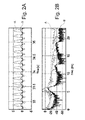
figures 2A and 2B both show the effect of interference on the radar estimation of the vibration, whereinfigure 2A illustrates the vibration measured by the radar with (curve B) and without (curve A) interference, whereasfigure 2B shows the spectrum of the vibration measured in both cases (with and without interference); -
figure 3 illustrates the method for the remote measuring of vibrations and displacements with radar systems according to the present invention, in which said measurement removes the interference from stationary targets obtained by means of a suitable periodic calibration technique; -
figure 4 represents the scheme of a calibration device capable of generating vibrations with a known frequency, provided with anchoring means to the structure to be monitored. In this embodiment example, the calibration device consists of a reflector and an actuator-shaker or vibrator and the above anchoring means; -
figure 5 is a graph in which, representing the radar signal in the range, frequency domain, the contributions of the motion of the vibrating system (shaker) in the calibration phase (frequency 6 Hz) can be distinguished with respect to those due to interfering targets in slow movement (almost zero frequency); -
figure 6 shows a system that verifies the performances of the kinematic calibration method according to the present invention, which estimates the vibration of a target assembled on a precision actuator-shaker for the "sweep frequency" test; and -
figures 7A and 7B show an estimation of the measurement of two vibrations equal to 90 Hz (figure 7A ) and 590 Hz (figure 7B ), with a comparison of the measurement obtained by the radar system (SRR) with the accelerometric measurement. The optimum vibration frequency of the calibration target can be accurately determined thanks to the measurements indicated. - With reference to the figures, these show a method and kinematic calibration system for measuring displacements and vibrations of objects/structures according to the present invention, in particular a method and system which use a radar interferometry technique. The precise estimation of the position and displacement of an item/structure (indicated with P) using a single radar device (indicated with Q) with the interferometric technique exploits a knowledge of the reflection phase of the radar waves (having removed the ambiguity of multiples of 2n) for determining the "LOS" (acronym of "line of sight") distance RLOs(t) between the radar device Q and the item/structure P:


- The measurement of the phase ϕ, on the basis of equations (3) and (4), allows the variation in the distance RLOS(t) between the radar device Q and the item/structure P, to be known, in multiple time ranges of the repetition period T, as per
equation 4. This measurement of the phase ϕ, can be altered by the presence of various interfering targets I1, I2 positioned at the same distance from the radar device Q or, in other words, within the resolution of the same radar device Q, with respect to the object /structure P, as shown infigure 1A . -
Figure 1A , in fact, shows two interfering targets I1, I2 positioned at the same distance, and therefore isochronous, with respect to the object/structure P, or "useful" target. As the radar device Q is a linear system, the result of the interference is given by the sum of the contribution of the object /structure P, represented as a vector infigure 1B , and the interfering contribution I, represented with a different vector in the samefigure 1B . The amplitudes of the vectors P and I are proportional to the reflectivity, or "radar cross section", of the object /structure P and interfering targets I1, I2 respectively, in the measurement field. The phase of the vector P forms the useful signal ϕ, whereas the phase of the interfering vector I is not generally known, depending on the position, amplitude and reflection coefficient of all the targets In forming the interference. The result of the measurement is the phase of the sum P + I of the two contributions, i.e. ϕ t , that can differ considerably from the contribution ϕ to be measured, depending on the amplitudes of P and I, as shown infigure 1B . - An example of an estimation of a sinusoidal vibration in the presence of interference is shown in
figures 2A and 2B . The ideal motion (curve A) is strongly distorted (curve B) and higher harmonic components are generated. - The separation of the interfering contribution is relatively easy, using techniques known in literature, if the target moves significantly, in the order of much more than half a wavelength, but it is not easy if the motion is extremely reduced. The demodulated complex radar signal s(t) is the sum of the contribution of the interfering targets I1, I2 and object /structure P in vibrational movement, and can be decomposed as follows:

- The estimation of the interfering contribution, i.e. AIe jϕ I, is effected by means of a statistical technique based on a knowledge of the phase term ϕ P(t) due to the vibrational movement induced in equation (5). An example of the two contributions APe jϕP(t) e AIe jϕI of equation (5) is shown in the range-frequency graph of
figure 5 , which indicates the Fourier transform of the demodulated complex radar signal s(t) in different range positions. - The complete calibration procedure shown in
figure 3 consists in two phases: - 1. calibration phase. A vibration is induced in the object /structure P by means of a suitable actuator device. The frequency and duration of said vibration is known and is measured, for example, in the absence of interferences. In this case, the complex contribution P (
figure 1B ) is known for each instant of time during the measurement. This information can be exploited for estimating the interfering contribution I, assuming that it is kept constant, or moves only slightly with respect to the wavelength, for the whole duration of the measurement, as can be seen in equation (5); - 2. measurement phase. The interfering contribution I thus determined is subtracted from the signal measured by the radar device Q, obtaining a signal without interference, whose phase is used for measuring the vibration as per equation (3) and equation (4).
- The calibration phase is repeated periodically, as indicated in
figure 3 , for updating the estimation of the interfering contribution I with respect to possible changes in the interference (slow movements, amplitudes, etc.). - The kinematic calibration device according to the invention is represented in
figure 4 . Said calibration device consists of: - a
reflector element 12 of the trihedral type, or produced with other geometrical forms or construction details so as to be visible by the radar device Q; - hooking or anchoring means 14, configured for making the calibration device (10) integral with the object /structure P whose movement is to be measured;
- a
vibration mechanism 16 which allows thetarget 12 to vibrate with its own motion with respect to the object /structure P whose movement is to be measured. - The
vibration mechanism 16 can be mechanically activated or powered by batteries, as for systems used in mobile phones, and must be periodically activated and deactivated. When thevibration mechanism 16 is deactivated, thereflector element 12 moves integrally with the object /structure P. Themechanism 16 is produced so as to periodically repeat the same vibration, with a better precision than the wavelength. - The
vibration mechanism 16 can operate according to different modes. An example of a vibration can consist in a sinusoidal motion generated by thevibration mechanism 16 by a battery motor and a cam. In the case of linear motion (or similar), it is well-known that the adapted filter is represented by the Fourier transform. -
Figure 5 shows the module of said Fourier transform, measured for each possible distance ("range") between target and radar system. It can be immediately observed that this result allows the contribution of the vibrating target, that can be identified at a distance of about 12 m and a frequency of 6 Hz, to be separated with respect to all the other contributions. The complex amplitude of the target, measured in correspondence with the peak (6 Hz and 12 m), provides the estimation of the complex contribution P offigure 1B . The estimation of the vector I, on the other hand, is given by the complex contribution P measured at null frequency. - A further example of application of the method according to the invention was effected by equipping a vibration actuator (shaker) having wide-range frequencies with a target visible to the radar system, in order to verify the sensitivity of the same radar system to the variation in frequency and therefore to effectively and accurately calibrate the receiving and
calibration device 10. -
Figure 6 shows an example of a verification system of the performances of the calibration method according to the invention. The verification system effects an estimation of the vibration of a target assembled on a precision actuator (shaker) for measurement tests of the vibrations with a variation in the "sweep frequency". - Finally,
figures 7A and 7B show the results of radar estimations of two known vibrations equal to 90 Hz and 590 Hz with respect to a reference accelerometer. The optimum vibration frequency of the calibration target, object of the method according to the invention, can be accurately determined thanks to the measurements indicated. - It can thus be seen that the method and kinematic calibration system for the measurement of displacements and vibrations of objects /structures according to the present invention achieve the objectives previously specified.
- The method and kinematic calibration system for the measurement of displacements and vibrations of items/structures of the present invention thus conceived, can in any case undergo numerous modifications and variants, all included in the same inventive concept. The protection scope of the invention is therefore defined by the enclosed claims.
Claims (10)
- A method for measuring displacements and vibrations of an object /structure (P), the method comprising the following steps:- transmission of at least one radar wave by a single radar device (Q) placed at a predefined distance (R) from a receiver device (10) applied on the object /structure (P);- reception, by the radar device (Q), of a complex signal (s(t)) consisting of the sum of the signal reflected from said receiver device (10) and of one or more interfering signals (I) generated by one or more corresponding targets (I1, I2) substantially stationary and substantially positioned at the same distance (R) from said radar device (Q); and- separation of said one or more interfering signals (I) from said reflected signal,
wherein said separation step comprises a calibration step consisting of:- induction, for a pre-determined period of time, of a vibrational motion having a known frequency and duration in the receiver device (10), which consequently operates as a calibration device, for obtaining an estimated value of said one or more interfering signals (I); and- subtraction of the estimated value of said one or more interfering signals (I) from the complex signal (s(t)), in order to substantially eliminate said one or more interfering signals (I) and obtain the entity of the displacement of the item/structure (P) on the basis of the calibrated reflected signal. - The method according to claim 1, wherein the value of the displacement of the object /structure (P) is calculated on the basis of the variation, as a function of time, of the distance (RLOS(t)) between the radar device (Q) and the object /structure (P).
- The method according to claim 2, wherein the distance (RLOS(t)), as a function of time, between the radar device (Q) and the item/structure (P) is equal to:

- The method according to claim 3, wherein the phase ϕ is periodically measured, i.e. with repetitions of transmissions, in correspondence with the times tn equal to:

- The method according to claim 4, wherein the measurement of the phase ϕ allows the variation in the distance (RLOS(t)), as a function of time, between the radar device (Q) and the object /structure (P) to be known for multiple time intervals of the repetition period T.
- The method according any of the claims from 1 to 5, wherein the calibration step is periodically repeated in order to update the estimated value of said one or more interfering signals (I) with respect to possible changes in the interference.
- The method according to claim 6, wherein the estimation step of the vibration of the object /structure is performed following the temporary interruption of the vibrational motion induced in the receiver or calibration device (10).
- The method according any of the claims from 1 to 7, wherein the vibrational motion is a sinusoidal motion.
- A system for measuring displacements and vibrations of an object /structure (P), the system comprising:- at least one receiver or calibration device (10) applied on the object /structure (P); and- at least one radar device (Q) positioned at a predefined distance (R) from the receiver or calibration device (10) and capable of transmitting at least one radar wave to said receiver or calibration device (10);
wherein said receiver or calibration device (10) consists of:- a reflector element (12) configured so as to be visible by the radar device (Q);- a hooking or anchoring means (14) configured for making said receiver or calibration device (10) integral with the object /structure (P); and- a vibration mechanism (16) which allows said receiver or calibration (10) device to be moved with its own motion with respect to the object /structure (P). - The system according to claim 9, wherein the vibration mechanism (16) is equipped with an electric motor fed by a battery and with a cam, and is capable of generating a vibrational motion of the sinusoidal type.
Applications Claiming Priority (1)
| Application Number | Priority Date | Filing Date | Title |
|---|---|---|---|
| ITMI20140771 | 2014-04-24 |
Publications (2)
| Publication Number | Publication Date |
|---|---|
| EP2937710A1 true EP2937710A1 (en) | 2015-10-28 |
| EP2937710B1 EP2937710B1 (en) | 2018-03-14 |
Family
ID=51033338
Family Applications (1)
| Application Number | Title | Priority Date | Filing Date |
|---|---|---|---|
| EP15164873.0A Active EP2937710B1 (en) | 2014-04-24 | 2015-04-23 | Method and kinematic calibration system for measuring displacements and vibrations of objects/structures |
Country Status (7)
| Country | Link |
|---|---|
| US (1) | US10006988B2 (en) |
| EP (1) | EP2937710B1 (en) |
| CY (1) | CY1120614T1 (en) |
| DK (1) | DK2937710T3 (en) |
| EA (1) | EA031205B1 (en) |
| NO (1) | NO2937710T3 (en) |
| TR (1) | TR201808111T4 (en) |
Cited By (2)
| Publication number | Priority date | Publication date | Assignee | Title |
|---|---|---|---|---|
| CN113419222A (en) * | 2021-05-10 | 2021-09-21 | 北方工业大学 | Method and system for extracting bridge vibration frequency based on radar signals |
| WO2022249126A1 (en) * | 2021-05-28 | 2022-12-01 | Eni S.P.A. | Reflectometric system and method for measuring vibrations or deformations of objects/structures |
Families Citing this family (7)
| Publication number | Priority date | Publication date | Assignee | Title |
|---|---|---|---|---|
| US10630397B2 (en) * | 2017-06-09 | 2020-04-21 | Keysight Technologies, Inc. | System and method for measuring free-space parameters of an antenna |
| CN108983229B (en) * | 2018-05-03 | 2022-04-19 | 电子科技大学 | High-voltage transmission tower height and deformation extraction method based on SAR (synthetic aperture radar) chromatography technology |
| US10914819B2 (en) * | 2018-08-02 | 2021-02-09 | GM Global Technology Operations LLC | Mitigating vibration in a radar system on a moving platform |
| CN112285663B (en) * | 2020-11-18 | 2023-10-17 | 中国铁道科学研究院集团有限公司 | Method and device for calibrating vibration degree of vehicle-mounted radar by using geological radar signals |
| WO2024082117A1 (en) * | 2022-10-18 | 2024-04-25 | 日立楼宇技术(广州)有限公司 | Radar ranging method and apparatus, and device and storage medium |
| JP2025085527A (en) * | 2023-11-24 | 2025-06-05 | 京セラ株式会社 | Electronic device, electronic device control method, and program |
| JP2025173412A (en) * | 2024-05-14 | 2025-11-27 | 京セラ株式会社 | Vibration detection method |
Citations (7)
| Publication number | Priority date | Publication date | Assignee | Title |
|---|---|---|---|---|
| EP1178330A1 (en) | 1993-04-12 | 2002-02-06 | The Regents Of The University Of California | Ultra-wideband radar motion sensor |
| US20060260407A1 (en) | 1999-08-23 | 2006-11-23 | The Trustees Of The Stevens Institute Of Technology | Method and apparatus for remote measurement of vibration and properties of objects |
| US20070085730A1 (en) * | 2005-10-19 | 2007-04-19 | General Atomics | Compact radar test range |
| EP2382487A1 (en) | 2008-12-31 | 2011-11-02 | IDS Ingegneria Dei Sistemi S.p.A. | Method for interferometric radar measurements |
| US20110298655A1 (en) | 2010-06-07 | 2011-12-08 | ELLEGI S.r.l.. | Synthetic-aperture radar system and operating method for monitoring ground and structure displacements suitable for emergency conditions |
| EP2560021A1 (en) * | 2011-08-18 | 2013-02-20 | Linear Technology Corporation | Radar system and method for providing information on movements of object's surface |
| WO2013118121A1 (en) * | 2012-02-11 | 2013-08-15 | Ilan Saul Barak | A microwave contactless heart rate sensor |
Family Cites Families (13)
| Publication number | Priority date | Publication date | Assignee | Title |
|---|---|---|---|---|
| DE2815773C3 (en) * | 1978-04-12 | 1981-07-16 | Wilfried Prof. Dr.-Ing. 2100 Hamburg Fritzsche | Warning system for traffic routes on an avalanche-prone mountain slope |
| GB2310099B (en) * | 1996-02-08 | 2000-08-02 | Mecon Limited | Radar for vibration detection |
| JP3105867B2 (en) * | 1998-07-03 | 2000-11-06 | 日本電気株式会社 | Synthetic aperture radar system, platform position measuring method used therefor, and recording medium recording its control program |
| CA2615803A1 (en) * | 2005-07-25 | 2007-02-01 | Groundprobe Pty Ltd. | Method and system of determining alarm conditions |
| US7825669B2 (en) * | 2007-03-29 | 2010-11-02 | Hamilton Sundstrand Corporation | Microwave position sensing for a turbo machine |
| RU2352909C1 (en) * | 2007-07-23 | 2009-04-20 | Тихоокеанский военно-морской институт им. С.О. Макарова | Method for radiolocating measurement of vessel hull vibration and device for its realisation |
| WO2010030630A1 (en) * | 2008-09-09 | 2010-03-18 | New York University | Method and devices to increase craniofacial bone density |
| RU2426974C2 (en) * | 2008-12-01 | 2011-08-20 | Владимир Иванович Винокуров | Procedure for determination of amplitude of oscillations of turbo-machine blades and device for its implementation |
| RU2446411C2 (en) * | 2009-05-29 | 2012-03-27 | Общество с ограниченной ответственностью "Научно-исследовательский институт природных газов и газовых технологий - Газпром ВНИИГАЗ" (ООО "Газпром ВНИИГАЗ") | Method of monitoring displacements of earth's surface and deformation of structures on territory of mineral deposits |
| US9194944B2 (en) * | 2010-07-14 | 2015-11-24 | Hitachi, Ltd. | Measurement device |
| US8638253B1 (en) * | 2010-11-12 | 2014-01-28 | Bbn Technologies Corp. | Vibrating radar sensor |
| US8963732B2 (en) * | 2011-01-28 | 2015-02-24 | Groundprobe Pty Ltd | Slope stability alarm |
| US9856859B2 (en) * | 2012-06-26 | 2018-01-02 | Vestas Wind Systems A/S | Wind turbine blade vibration detection and radar calibration |
-
2015
- 2015-04-17 EA EA201590605A patent/EA031205B1/en not_active IP Right Cessation
- 2015-04-23 TR TR2018/08111T patent/TR201808111T4/en unknown
- 2015-04-23 DK DK15164873.0T patent/DK2937710T3/en active
- 2015-04-23 EP EP15164873.0A patent/EP2937710B1/en active Active
- 2015-04-23 US US14/693,984 patent/US10006988B2/en active Active
- 2015-04-23 NO NO15164873A patent/NO2937710T3/no unknown
-
2018
- 2018-06-07 CY CY181100598T patent/CY1120614T1/en unknown
Patent Citations (7)
| Publication number | Priority date | Publication date | Assignee | Title |
|---|---|---|---|---|
| EP1178330A1 (en) | 1993-04-12 | 2002-02-06 | The Regents Of The University Of California | Ultra-wideband radar motion sensor |
| US20060260407A1 (en) | 1999-08-23 | 2006-11-23 | The Trustees Of The Stevens Institute Of Technology | Method and apparatus for remote measurement of vibration and properties of objects |
| US20070085730A1 (en) * | 2005-10-19 | 2007-04-19 | General Atomics | Compact radar test range |
| EP2382487A1 (en) | 2008-12-31 | 2011-11-02 | IDS Ingegneria Dei Sistemi S.p.A. | Method for interferometric radar measurements |
| US20110298655A1 (en) | 2010-06-07 | 2011-12-08 | ELLEGI S.r.l.. | Synthetic-aperture radar system and operating method for monitoring ground and structure displacements suitable for emergency conditions |
| EP2560021A1 (en) * | 2011-08-18 | 2013-02-20 | Linear Technology Corporation | Radar system and method for providing information on movements of object's surface |
| WO2013118121A1 (en) * | 2012-02-11 | 2013-08-15 | Ilan Saul Barak | A microwave contactless heart rate sensor |
Non-Patent Citations (2)
| Title |
|---|
| ENDER, J.: "Space-time processing for multichannel synthetic aperture radar", ELECTRONICS & COMMUNICATION ENGINEERING JOURNAL, February 1999 (1999-02-01) |
| MELVIN, W.L.: "A STAP overview", AEROSPACE AND ELECTRONIC SYSTEMS MAGAZINE, IEEE, vol. 19, no. 1, January 2004 (2004-01-01), pages 19 - 35, XP011106327, DOI: doi:10.1109/MAES.2004.1263229 |
Cited By (3)
| Publication number | Priority date | Publication date | Assignee | Title |
|---|---|---|---|---|
| CN113419222A (en) * | 2021-05-10 | 2021-09-21 | 北方工业大学 | Method and system for extracting bridge vibration frequency based on radar signals |
| CN113419222B (en) * | 2021-05-10 | 2022-12-16 | 北方工业大学 | Method and system for extracting bridge vibration frequency based on radar signal |
| WO2022249126A1 (en) * | 2021-05-28 | 2022-12-01 | Eni S.P.A. | Reflectometric system and method for measuring vibrations or deformations of objects/structures |
Also Published As
| Publication number | Publication date |
|---|---|
| US10006988B2 (en) | 2018-06-26 |
| EA201590605A1 (en) | 2016-01-29 |
| CY1120614T1 (en) | 2019-12-11 |
| US20150309160A1 (en) | 2015-10-29 |
| TR201808111T4 (en) | 2018-07-23 |
| EP2937710B1 (en) | 2018-03-14 |
| NO2937710T3 (en) | 2018-08-11 |
| DK2937710T3 (en) | 2018-06-18 |
| EA031205B1 (en) | 2018-11-30 |
Similar Documents
| Publication | Publication Date | Title |
|---|---|---|
| EP2937710B1 (en) | Method and kinematic calibration system for measuring displacements and vibrations of objects/structures | |
| EP2937711B1 (en) | Method and system for the remote monitoring of the two/three-dimensional field of displacements and vibrations of objects/structures | |
| JP7667331B2 (en) | Method and apparatus for capturing surroundings - Patents.com | |
| EP4080242B1 (en) | Radar communications with disparate pulse repetition intervals | |
| US10768276B2 (en) | Decentralised radar system | |
| US12468025B2 (en) | Systems and methods for doppler-enhanced radar tracking | |
| WO2007128703A1 (en) | A method for filtering sea clutter in a radar echo using a hydrographic model | |
| Amies et al. | Experimental validation of a radar-based structural health monitoring system | |
| Zeintl et al. | Evaluation of FMCW radar for vibration sensing in industrial environments | |
| GB2487374A (en) | Radar system synthesising a broadband waveform from a series of narrowband chirps and accounting for Doppler of a target between chirps | |
| US20240248173A1 (en) | Reflectometric system and method for measuring vibrations or deformations of objects/structures | |
| Moll et al. | Motion sensing of a wind turbine prototype using a bistatic FMCW Doppler radar sensor | |
| US12055645B2 (en) | System and method for positioning and navigation of an object | |
| Maizuar et al. | Dynamic monitoring of bridges: Accelerometer vs microwave radar interferometry (IBIS-S) | |
| US10247843B2 (en) | System and method for measuring the width of a fault on a site to be monitored | |
| KR20180101002A (en) | Angle Estimation Method and Apparatus for Automotive Radars | |
| Vavriv et al. | Cost-effective Ku-band airborne SAR with Doppler centroid estimation, autofocusing, and indication of moving targets | |
| Amies et al. | Shake Table Testing of a Radar-Based Structural Health Monitoring Method | |
| RU2621473C1 (en) | Device for remote measuring mutual element displacement of buildings and structures | |
| EP4644947A1 (en) | Improved virtual target generator | |
| Nurzaman et al. | Micro-Doppler Extraction from Ground-Based SAR Data using Interferometry Approach | |
| Van Groenestiin et al. | Quantifying the performance of state of the art sensors to measure guided elastic waves | |
| Amies et al. | Simulating and testing a non-contact structural health monitoring system | |
| El-Mokdad et al. | FMCW implementation on LABVIEW | |
| Lutsenko et al. | Illumination of air environment using radiation of SW broadcasting stations |
Legal Events
| Date | Code | Title | Description |
|---|---|---|---|
| PUAI | Public reference made under article 153(3) epc to a published international application that has entered the european phase |
Free format text: ORIGINAL CODE: 0009012 |
|
| AK | Designated contracting states |
Kind code of ref document: A1 Designated state(s): AL AT BE BG CH CY CZ DE DK EE ES FI FR GB GR HR HU IE IS IT LI LT LU LV MC MK MT NL NO PL PT RO RS SE SI SK SM TR |
|
| AX | Request for extension of the european patent |
Extension state: BA ME |
|
| 17P | Request for examination filed |
Effective date: 20160426 |
|
| RBV | Designated contracting states (corrected) |
Designated state(s): AL AT BE BG CH CY CZ DE DK EE ES FI FR GB GR HR HU IE IS IT LI LT LU LV MC MK MT NL NO PL PT RO RS SE SI SK SM TR |
|
| GRAP | Despatch of communication of intention to grant a patent |
Free format text: ORIGINAL CODE: EPIDOSNIGR1 |
|
| RIC1 | Information provided on ipc code assigned before grant |
Ipc: G01S 7/40 20060101ALI20170829BHEP Ipc: G01S 13/58 20060101ALI20170829BHEP Ipc: G01S 7/35 20060101AFI20170829BHEP |
|
| STAA | Information on the status of an ep patent application or granted ep patent |
Free format text: STATUS: GRANT OF PATENT IS INTENDED |
|
| INTG | Intention to grant announced |
Effective date: 20171005 |
|
| GRAS | Grant fee paid |
Free format text: ORIGINAL CODE: EPIDOSNIGR3 |
|
| GRAA | (expected) grant |
Free format text: ORIGINAL CODE: 0009210 |
|
| STAA | Information on the status of an ep patent application or granted ep patent |
Free format text: STATUS: THE PATENT HAS BEEN GRANTED |
|
| AK | Designated contracting states |
Kind code of ref document: B1 Designated state(s): AL AT BE BG CH CY CZ DE DK EE ES FI FR GB GR HR HU IE IS IT LI LT LU LV MC MK MT NL NO PL PT RO RS SE SI SK SM TR |
|
| REG | Reference to a national code |
Ref country code: GB Ref legal event code: FG4D |
|
| REG | Reference to a national code |
Ref country code: CH Ref legal event code: EP Ref country code: AT Ref legal event code: REF Ref document number: 979420 Country of ref document: AT Kind code of ref document: T Effective date: 20180315 |
|
| REG | Reference to a national code |
Ref country code: IE Ref legal event code: FG4D |
|
| REG | Reference to a national code |
Ref country code: DE Ref legal event code: R096 Ref document number: 602015008648 Country of ref document: DE |
|
| REG | Reference to a national code |
Ref country code: FR Ref legal event code: PLFP Year of fee payment: 4 |
|
| REG | Reference to a national code |
Ref country code: DK Ref legal event code: T3 Effective date: 20180611 |
|
| REG | Reference to a national code |
Ref country code: NL Ref legal event code: FP |
|
| REG | Reference to a national code |
Ref country code: LT Ref legal event code: MG4D |
|
| PG25 | Lapsed in a contracting state [announced via postgrant information from national office to epo] |
Ref country code: LT Free format text: LAPSE BECAUSE OF FAILURE TO SUBMIT A TRANSLATION OF THE DESCRIPTION OR TO PAY THE FEE WITHIN THE PRESCRIBED TIME-LIMIT Effective date: 20180314 Ref country code: FI Free format text: LAPSE BECAUSE OF FAILURE TO SUBMIT A TRANSLATION OF THE DESCRIPTION OR TO PAY THE FEE WITHIN THE PRESCRIBED TIME-LIMIT Effective date: 20180314 Ref country code: HR Free format text: LAPSE BECAUSE OF FAILURE TO SUBMIT A TRANSLATION OF THE DESCRIPTION OR TO PAY THE FEE WITHIN THE PRESCRIBED TIME-LIMIT Effective date: 20180314 |
|
| REG | Reference to a national code |
Ref country code: NO Ref legal event code: T2 Effective date: 20180314 |
|
| PG25 | Lapsed in a contracting state [announced via postgrant information from national office to epo] |
Ref country code: LV Free format text: LAPSE BECAUSE OF FAILURE TO SUBMIT A TRANSLATION OF THE DESCRIPTION OR TO PAY THE FEE WITHIN THE PRESCRIBED TIME-LIMIT Effective date: 20180314 Ref country code: SE Free format text: LAPSE BECAUSE OF FAILURE TO SUBMIT A TRANSLATION OF THE DESCRIPTION OR TO PAY THE FEE WITHIN THE PRESCRIBED TIME-LIMIT Effective date: 20180314 Ref country code: RS Free format text: LAPSE BECAUSE OF FAILURE TO SUBMIT A TRANSLATION OF THE DESCRIPTION OR TO PAY THE FEE WITHIN THE PRESCRIBED TIME-LIMIT Effective date: 20180314 Ref country code: BG Free format text: LAPSE BECAUSE OF FAILURE TO SUBMIT A TRANSLATION OF THE DESCRIPTION OR TO PAY THE FEE WITHIN THE PRESCRIBED TIME-LIMIT Effective date: 20180614 |
|
| PG25 | Lapsed in a contracting state [announced via postgrant information from national office to epo] |
Ref country code: AL Free format text: LAPSE BECAUSE OF FAILURE TO SUBMIT A TRANSLATION OF THE DESCRIPTION OR TO PAY THE FEE WITHIN THE PRESCRIBED TIME-LIMIT Effective date: 20180314 Ref country code: RO Free format text: LAPSE BECAUSE OF FAILURE TO SUBMIT A TRANSLATION OF THE DESCRIPTION OR TO PAY THE FEE WITHIN THE PRESCRIBED TIME-LIMIT Effective date: 20180314 Ref country code: ES Free format text: LAPSE BECAUSE OF FAILURE TO SUBMIT A TRANSLATION OF THE DESCRIPTION OR TO PAY THE FEE WITHIN THE PRESCRIBED TIME-LIMIT Effective date: 20180314 Ref country code: EE Free format text: LAPSE BECAUSE OF FAILURE TO SUBMIT A TRANSLATION OF THE DESCRIPTION OR TO PAY THE FEE WITHIN THE PRESCRIBED TIME-LIMIT Effective date: 20180314 Ref country code: PL Free format text: LAPSE BECAUSE OF FAILURE TO SUBMIT A TRANSLATION OF THE DESCRIPTION OR TO PAY THE FEE WITHIN THE PRESCRIBED TIME-LIMIT Effective date: 20180314 |
|
| REG | Reference to a national code |
Ref country code: GR Ref legal event code: EP Ref document number: 20180401578 Country of ref document: GR Effective date: 20181031 |
|
| PG25 | Lapsed in a contracting state [announced via postgrant information from national office to epo] |
Ref country code: SM Free format text: LAPSE BECAUSE OF FAILURE TO SUBMIT A TRANSLATION OF THE DESCRIPTION OR TO PAY THE FEE WITHIN THE PRESCRIBED TIME-LIMIT Effective date: 20180314 Ref country code: SK Free format text: LAPSE BECAUSE OF FAILURE TO SUBMIT A TRANSLATION OF THE DESCRIPTION OR TO PAY THE FEE WITHIN THE PRESCRIBED TIME-LIMIT Effective date: 20180314 Ref country code: CZ Free format text: LAPSE BECAUSE OF FAILURE TO SUBMIT A TRANSLATION OF THE DESCRIPTION OR TO PAY THE FEE WITHIN THE PRESCRIBED TIME-LIMIT Effective date: 20180314 |
|
| REG | Reference to a national code |
Ref country code: CH Ref legal event code: PL |
|
| REG | Reference to a national code |
Ref country code: DE Ref legal event code: R097 Ref document number: 602015008648 Country of ref document: DE |
|
| PG25 | Lapsed in a contracting state [announced via postgrant information from national office to epo] |
Ref country code: PT Free format text: LAPSE BECAUSE OF FAILURE TO SUBMIT A TRANSLATION OF THE DESCRIPTION OR TO PAY THE FEE WITHIN THE PRESCRIBED TIME-LIMIT Effective date: 20180716 |
|
| PLBE | No opposition filed within time limit |
Free format text: ORIGINAL CODE: 0009261 |
|
| STAA | Information on the status of an ep patent application or granted ep patent |
Free format text: STATUS: NO OPPOSITION FILED WITHIN TIME LIMIT |
|
| REG | Reference to a national code |
Ref country code: IE Ref legal event code: MM4A |
|
| PG25 | Lapsed in a contracting state [announced via postgrant information from national office to epo] |
Ref country code: MC Free format text: LAPSE BECAUSE OF FAILURE TO SUBMIT A TRANSLATION OF THE DESCRIPTION OR TO PAY THE FEE WITHIN THE PRESCRIBED TIME-LIMIT Effective date: 20180314 Ref country code: LU Free format text: LAPSE BECAUSE OF NON-PAYMENT OF DUE FEES Effective date: 20180423 |
|
| 26N | No opposition filed |
Effective date: 20181217 |
|
| PG25 | Lapsed in a contracting state [announced via postgrant information from national office to epo] |
Ref country code: CH Free format text: LAPSE BECAUSE OF NON-PAYMENT OF DUE FEES Effective date: 20180430 Ref country code: SI Free format text: LAPSE BECAUSE OF FAILURE TO SUBMIT A TRANSLATION OF THE DESCRIPTION OR TO PAY THE FEE WITHIN THE PRESCRIBED TIME-LIMIT Effective date: 20180314 Ref country code: LI Free format text: LAPSE BECAUSE OF NON-PAYMENT OF DUE FEES Effective date: 20180430 |
|
| PG25 | Lapsed in a contracting state [announced via postgrant information from national office to epo] |
Ref country code: IE Free format text: LAPSE BECAUSE OF NON-PAYMENT OF DUE FEES Effective date: 20180423 |
|
| PG25 | Lapsed in a contracting state [announced via postgrant information from national office to epo] |
Ref country code: MT Free format text: LAPSE BECAUSE OF NON-PAYMENT OF DUE FEES Effective date: 20180423 |
|
| REG | Reference to a national code |
Ref country code: AT Ref legal event code: UEP Ref document number: 979420 Country of ref document: AT Kind code of ref document: T Effective date: 20180314 |
|
| PG25 | Lapsed in a contracting state [announced via postgrant information from national office to epo] |
Ref country code: HU Free format text: LAPSE BECAUSE OF FAILURE TO SUBMIT A TRANSLATION OF THE DESCRIPTION OR TO PAY THE FEE WITHIN THE PRESCRIBED TIME-LIMIT; INVALID AB INITIO Effective date: 20150423 Ref country code: MK Free format text: LAPSE BECAUSE OF NON-PAYMENT OF DUE FEES Effective date: 20180314 |
|
| PG25 | Lapsed in a contracting state [announced via postgrant information from national office to epo] |
Ref country code: IS Free format text: LAPSE BECAUSE OF FAILURE TO SUBMIT A TRANSLATION OF THE DESCRIPTION OR TO PAY THE FEE WITHIN THE PRESCRIBED TIME-LIMIT Effective date: 20180714 |
|
| P01 | Opt-out of the competence of the unified patent court (upc) registered |
Effective date: 20230530 |
|
| PGFP | Annual fee paid to national office [announced via postgrant information from national office to epo] |
Ref country code: NL Payment date: 20250422 Year of fee payment: 11 |
|
| PGFP | Annual fee paid to national office [announced via postgrant information from national office to epo] |
Ref country code: DE Payment date: 20250417 Year of fee payment: 11 |
|
| PGFP | Annual fee paid to national office [announced via postgrant information from national office to epo] |
Ref country code: GB Payment date: 20250423 Year of fee payment: 11 Ref country code: DK Payment date: 20250423 Year of fee payment: 11 |
|
| PGFP | Annual fee paid to national office [announced via postgrant information from national office to epo] |
Ref country code: NO Payment date: 20250422 Year of fee payment: 11 |
|
| PGFP | Annual fee paid to national office [announced via postgrant information from national office to epo] |
Ref country code: BE Payment date: 20250422 Year of fee payment: 11 Ref country code: IT Payment date: 20250430 Year of fee payment: 11 |
|
| PGFP | Annual fee paid to national office [announced via postgrant information from national office to epo] |
Ref country code: FR Payment date: 20250422 Year of fee payment: 11 |
|
| PGFP | Annual fee paid to national office [announced via postgrant information from national office to epo] |
Ref country code: GR Payment date: 20250416 Year of fee payment: 11 |
|
| PGFP | Annual fee paid to national office [announced via postgrant information from national office to epo] |
Ref country code: AT Payment date: 20250416 Year of fee payment: 11 |
|
| PGFP | Annual fee paid to national office [announced via postgrant information from national office to epo] |
Ref country code: TR Payment date: 20250415 Year of fee payment: 11 |
|
| PGFP | Annual fee paid to national office [announced via postgrant information from national office to epo] |
Ref country code: CY Payment date: 20250415 Year of fee payment: 11 |