EP2937684A1 - A method of testing the oxidation resistance of an alloy - Google Patents
A method of testing the oxidation resistance of an alloy Download PDFInfo
- Publication number
- EP2937684A1 EP2937684A1 EP15164188.3A EP15164188A EP2937684A1 EP 2937684 A1 EP2937684 A1 EP 2937684A1 EP 15164188 A EP15164188 A EP 15164188A EP 2937684 A1 EP2937684 A1 EP 2937684A1
- Authority
- EP
- European Patent Office
- Prior art keywords
- alloy
- salt
- testing
- coating
- test
- Prior art date
- Legal status (The legal status is an assumption and is not a legal conclusion. Google has not performed a legal analysis and makes no representation as to the accuracy of the status listed.)
- Granted
Links
Images




Classifications
-
- G—PHYSICS
- G01—MEASURING; TESTING
- G01N—INVESTIGATING OR ANALYSING MATERIALS BY DETERMINING THEIR CHEMICAL OR PHYSICAL PROPERTIES
- G01N5/00—Analysing materials by weighing, e.g. weighing small particles separated from a gas or liquid
-
- C—CHEMISTRY; METALLURGY
- C22—METALLURGY; FERROUS OR NON-FERROUS ALLOYS; TREATMENT OF ALLOYS OR NON-FERROUS METALS
- C22C—ALLOYS
- C22C19/00—Alloys based on nickel or cobalt
- C22C19/03—Alloys based on nickel or cobalt based on nickel
- C22C19/05—Alloys based on nickel or cobalt based on nickel with chromium
- C22C19/051—Alloys based on nickel or cobalt based on nickel with chromium and Mo or W
- C22C19/057—Alloys based on nickel or cobalt based on nickel with chromium and Mo or W with the maximum Cr content being less 10%
-
- G—PHYSICS
- G01—MEASURING; TESTING
- G01N—INVESTIGATING OR ANALYSING MATERIALS BY DETERMINING THEIR CHEMICAL OR PHYSICAL PROPERTIES
- G01N1/00—Sampling; Preparing specimens for investigation
- G01N1/28—Preparing specimens for investigation including physical details of (bio-)chemical methods covered elsewhere, e.g. G01N33/50, C12Q
- G01N1/44—Sample treatment involving radiation, e.g. heat
-
- G—PHYSICS
- G01—MEASURING; TESTING
- G01N—INVESTIGATING OR ANALYSING MATERIALS BY DETERMINING THEIR CHEMICAL OR PHYSICAL PROPERTIES
- G01N17/00—Investigating resistance of materials to the weather, to corrosion, or to light
- G01N17/006—Investigating resistance of materials to the weather, to corrosion, or to light of metals
-
- G—PHYSICS
- G01—MEASURING; TESTING
- G01N—INVESTIGATING OR ANALYSING MATERIALS BY DETERMINING THEIR CHEMICAL OR PHYSICAL PROPERTIES
- G01N5/00—Analysing materials by weighing, e.g. weighing small particles separated from a gas or liquid
- G01N5/04—Analysing materials by weighing, e.g. weighing small particles separated from a gas or liquid by removing a component, e.g. by evaporation, and weighing the remainder
-
- C—CHEMISTRY; METALLURGY
- C22—METALLURGY; FERROUS OR NON-FERROUS ALLOYS; TREATMENT OF ALLOYS OR NON-FERROUS METALS
- C22C—ALLOYS
- C22C27/00—Alloys based on rhenium or a refractory metal not mentioned in groups C22C14/00 or C22C16/00
- C22C27/06—Alloys based on chromium
-
- C—CHEMISTRY; METALLURGY
- C22—METALLURGY; FERROUS OR NON-FERROUS ALLOYS; TREATMENT OF ALLOYS OR NON-FERROUS METALS
- C22C—ALLOYS
- C22C5/00—Alloys based on noble metals
- C22C5/04—Alloys based on a platinum group metal
Definitions
- the present disclosure relates to a method of testing the oxidation resistance of an alloy and in particular to an apparatus and a method of testing the oxidation resistance of a superalloy gas turbine engine component or a coating alloy on a superalloy gas turbine engine component.
- Superalloy components of gas turbine engines e.g. turbine blades, turbine vanes, combustion chambers, are operated in a wide range of temperatures, for example from 600°C to 1200°C.
- the temperature of operation of the superalloy component depends upon the position of the component within the gas turbine engine.
- it is essential to consider the environmental degradation of the superalloy, or the coating alloy, over all of the operating conditions that the superalloy component or the coating alloy will experience.
- Hot corrosion is most active at temperatures below about 950°C. Hot corrosion occurs whenever salt, ash or other airborne contaminant deposit accumulates on the surface of the superalloy component, or coating alloy, and hence alter the surface reactions. The severity of hot corrosion may vary substantially and depends upon the content of impurity in the intake air and the content of impurity in the fuel. There are two types of hot corrosion, Type I and Type II. Type I and Type II hot corrosion behaviour of superalloy components, or coating alloys, is tested using either burner rig testing or laboratory furnace testing. However, at temperatures above 1000°C oxidation is the dominant environmental degradation concern for superalloy components and coating alloys and oxidation is the life limiting factor for many superalloys and coating alloys.
- burner rig testing has been used to test superalloy components, or coating alloys, to assess their oxidation behaviour above temperatures of 1000°C.
- the burner rig test is capable of reproducing degradation mechanisms similar to those of an engine run blade/vane or an engine run blade/vane and coating.
- burner rig testing suffers from several problems. It is difficult to control the temperature within a specified margin of less than 10°C and especially so at temperatures above 1100°C. It is difficult to control contaminants deliberately introduced during a burner rig test. Burner rig testing has high operating costs due to the costs of the fuel and burner rig testing produces pollution. Burner rig testing is difficult with small quantities of superalloy or small quantities of coating alloy, e.g. small superalloy test pieces or small coating alloy samples on a superalloy test pieces. Burner rig testing has poor reproducibility from one burner rig to another resulting in substantial variation in lifing data generated by burner rigs at different sites.
- Cyclic oxidation testing in air has many advantages compared to burner rig testing. There is good control of temperature within a specified margin of less than 10°C. Cyclic oxidation testing in air may be used with small quantities of superalloy or small quantities of coating alloy, e.g. small superalloy test pieces or small coating alloy samples on a superalloy test pieces. Cyclic oxidation testing in air has good reproducibility from one cyclic oxidation testing rig to another. Cyclic oxidation testing has lower operating costs and cyclic oxidation testing produces significantly less pollution.
- cyclic oxidation testing cannot generate the degradation mechanism detected on superalloy gas turbine engine components, or coating alloys on gas turbine engine components, which have operated in a gas turbine engine because it has not taken into account the effects of contamination during the operation of the gas turbine engine. Cyclic oxidation testing has to be run for a long period of time, this may be 2000 to 4000 hours at 1100°C, to achieve any significant loss of material. The long operating periods of the cyclic oxidation testing increases the costs of the testing and impedes the development of new superalloys for components and the development of new coating alloys.
- the present disclosure seeks to provide a novel method of testing the oxidation resistance of a superalloy, or a coating alloy, which reduces or overcomes the above mentioned problem.
- the present disclosure provides a method of testing the oxidation resistance of an alloy comprising the steps of:-
- Step a) may comprise applying the layer of salt by spraying an aqueous solution of salt onto the surface of the alloy.
- Step a) may comprise spraying the aqueous solution of salt manually or semi-automatically.
- Step a) may comprise heating the alloy to a temperature of at least 120°C to evaporate the water to deposit the salt onto the surface of the alloy.
- Step a) may comprise heating the alloy before spraying the aqueous solution of salt onto the alloy or spraying the aqueous solution of salt onto the alloy and then heating the alloy.
- Step a) may comprise applying the layer of salt by providing a mist of an aqueous solution of salt and placing the alloy in the mist so that the mist deposits onto the surface of the alloy.
- Step d) may comprise cooling the alloy to ambient, or a suitable, temperature. Step a) and step d) may be performed at the same time.
- the oxygen containing gas may comprise air.
- the oxygen containing gas may comprise one or more of sulphur dioxide, sulphur trioxide and hydrogen chloride.
- the method may comprise applying the salt to the surface of the alloy at a level of 1 to 20 ⁇ g cm -2 h -1 .
- the method may comprise applying the salt to the surface of the alloy at a level of 7 ⁇ g cm -2 h -1 to 15 ⁇ g cm -2 h -1 .
- the method may comprise applying the salt to the surface of the alloy at a level of 7 ⁇ g cm -2 h -1 or 15 ⁇ g cm -2 h -1 .
- the method may comprise applying the salt to the surface of the alloy to give a surface coverage of 0.14mg cm -2 to 0.3mg cm -2 .
- the method may comprise applying the salt to the surface of the alloy to give a surface coverage of 0.14mg cm -2 .
- the method may comprise applying the salt to the surface of the alloy to give a surface coverage of 0.3mg cm -2 .
- the method may comprise reapplying the salt to the surface of the alloy every twenty 1 hour cycles.
- the salt may comprise a salt of one or more of the elements sodium, potassium, magnesium, calcium, vanadium, sulphur and chlorine.
- the salt may be sodium chloride, sea salt or sodium sulphate and sodium chloride.
- the sodium sulphate and sodium chloride may be Na 2 SO 4 - 2% NaCl.
- the predetermined temperature may be up to 1300°C.
- the predetermined temperature may be greater than or equal to 1100°C.
- the predetermined temperature may be greater than or equal to 1150°C.
- Step c) may comprise maintaining the alloy in the furnace at the predetermined temperature for 15 minutes, 30 minutes or 1 hour or other suitable time period.
- Step f) may comprise weighing the alloy every time steps a) to d) have been repeated a number of times.
- the alloy may be a superalloy or a coating alloy.
- the superalloy may be a nickel superalloy, a cobalt superalloy or an iron superalloy.
- the nickel superalloy may be a single crystal nickel superalloy and may comprise one or more of rhenium, ruthenium, yttrium and lanthanum.
- the coating alloy may be an MCrAlY, a platinum coating, an aluminide coating, a platinum aluminide coating, a chromium aluminide, platinum chromium aluminide coating, a silicide aluminide coating or a platinum silicide aluminide coating.
- the present disclosure also provides an apparatus for testing the oxidation resistance of an alloy comprising a furnace, an anti-chamber and a weight measuring apparatus, the furnace containing an oxygen containing gas, the anti-chamber being adjacent to, or connected, to the furnace, the anti-chamber having a spraying apparatus and the spraying apparatus comprising a supply of an aqueous solution of salt.
- the anti-chamber may have a mist spraying apparatus and the mist spraying apparatus comprising a supply of an aqueous solution of salt.
- the method may comprise determining the total weight loss of the alloy during the testing by subtracting the measured weight of the alloy at the end of the test from the measured weight of the alloy before the test.
- the method may include step g) cutting the alloy into two and step h) determining the dimension of a first portion of the alloy which has been oxidised, the dimension of a second portion of the alloy which has been depleted of strengthening elements and the dimension of a third portion of the alloy which has not been oxidised or been depleted of strengthening elements.
- Step h) may comprise measuring the dimension of the first portion of the alloy which has been oxidised, the dimension of the second portion of the alloy which has been depleted of strengthening elements and the dimension of the third portion of the alloy which has not been oxidised or been depleted of strengthening elements.
- the strengthening elements may include the element aluminium.
- the method may comprise determining the total loss of usable dimension of the alloy during the testing by subtracting the determined dimension of the third portion of the alloy at the end of the test from the measured dimension of the alloy before the test.
- the method may further include the step of i) correlating the total weight loss of the alloy during the test with the total loss of usable dimension of the alloy during the test.
- a turbofan gas turbine engine 10 as shown in figure 1 , comprises in flow series an intake 11, a fan 12, an intermediate pressure compressor 13, a high pressure compressor 14, a combustion chamber 15, a high pressure turbine 16, an intermediate pressure turbine 17, a low pressure turbine 18 and an exhaust 19.
- the high pressure turbine 16 is arranged to drive the high pressure compressor 14 via a first shaft 26.
- the intermediate pressure turbine 17 is arranged to drive the intermediate pressure compressor 13 via a second shaft 28 and the low pressure turbine 18 is arranged to drive the fan 12 via a third shaft 30.
- air flows into the intake 11 and is compressed by the fan 12.
- a first portion of the air flows through, and is compressed by, the intermediate pressure compressor 13 and the high pressure compressor 14 and is supplied to the combustion chamber 15.
- Fuel is injected into the combustion chamber 15 and is burnt in the air to produce hot exhaust gases which flow through, and drive, the high pressure turbine 16, the intermediate pressure turbine 17 and the low pressure turbine 18.
- the hot exhaust gases leaving the low pressure turbine 18 flow through the exhaust 19 to provide propulsive thrust.
- a second portion of the air bypasses the main engine to provide propulsive thrust.
- the high pressure turbine 16 comprises a turbine disc 38 and a plurality of turbine blades 40.
- the turbine disc 38 comprises a plurality of axially extending circumferentially spaced slots in the radially outer periphery and each turbine blade 40 locates in a respective one of the slots in the periphery of the turbine disc 38.
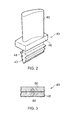
- One of the turbine blades 40 is shown in figure 2 .
- the turbine blade 40 comprises a root 42, a shank 44, a platform 46 and an aerofoil 48.
- the root 42 is shaped to locate in the slot in the periphery of the turbine disc 38 and in this example the root 42 is firtree shaped, but may be dovetail shaped.
- the turbine blade 40 consists of a superalloy and the superalloy may be a nickel superalloy, a cobalt superalloy or an iron superalloy.
- the nickel superalloy may be a single crystal nickel superalloy and may comprise one or more of rhenium, ruthenium, yttrium and lanthanum.
- the superalloy is a nickel superalloy and is a single crystal nickel superalloy, e.g. CMSX4.
- the aerofoil 48 and platform 46 of the turbine blade 40 may be provided with a protective coating, or a bond coating and a thermal barrier coating.
- the bond coating may be a protective coating.
- Figure 3 shows a protective coating 50 on the outer surface 49 of the aerofoil 48 of the turbine blade 40.
- the protective coating 50 may be oxidation resistant and/or corrosion resistant.
- the protective coating 50 consists of a suitable coating alloy and the coating alloy may be an MCrAlY, a platinum coating, an aluminide coating, a platinum aluminide coating, a chromium aluminide, platinum chromium aluminide coating, a silicide aluminide coating or a platinum silicide aluminide coating.
- An MCrAlY consists of chromium, aluminium and yttrium and one or more of nickel, cobalt and iron, as is well known to those skilled in the art.
- the MCrAlY coating is deposited by plasma spraying, thermal spraying or electron beam physical vapour deposition
- the aluminide type coatings are generally deposited by chemical vapour deposition.
- the aluminide silicide coatings may be deposited by slurry deposition.
- the platinum may be deposited by plating, e.g. electroplating, and the chromium may be deposited by plating or chemical vapour deposition.
- a method of testing the oxidation resistance of an alloy is shown in figure 4 .
- the method of testing the oxidation resistance of an alloy 51 comprises weighing the alloy at step 52 to determine the initial weight of the alloy, applying a layer of salt on the surface of the alloy at step 54, then placing the alloy in a furnace in step 56 and the furnace is at a predetermined temperature of at least 1000°C and contains an oxygen containing gas e.g. air.
- the alloy is maintained in the furnace at the predetermined temperature for a predetermined period of time in step 58 and then the alloy is removed from the furnace and allowed to cool to ambient temperature, or other suitable temperature, at step 60.
- Step 52 may also include measuring the dimension, or dimensions, e.g. diameter, or width and thickness, of the alloy.
- steps 54 to 60 are repeated for a first predetermined number of times, as shown by the repeat path, or loop, A.
- the resistance to oxidation test is stopped, as shown by path C, and step 62.
- the alloy is weighed to determine the final weight of the alloy at step 64.
- Figure 9 shows the temperature and time of steps 58 and 60 and in this particular example the alloy is maintained in the furnace at a temperature of 1273K, 1000°C, during step 58 and the alloy is cooled to ambient temperature of 293K, 20°C, at step 60.
- Figure 9 shows that the alloy is heated in the furnace from ambient temperature to 1273K during a heating time, then maintained in the furnace at the temperature of 1273K during a hot dwell time where T > 0.97 T dwell .
- Figure 9 shows that the alloy is cooled from 1273K to ambient temperature, or other suitable temperature, over a cooling time and then is maintained at ambient temperature, or other suitable temperature, for a cold dwell time where T ⁇ 323K, 50°C.
- the other suitable temperature is preferably less than 323K, 50°C.
- the alloy is periodically weighed after each of a second predetermined number of times that steps 54 to 60 have been repeated, as shown by path B, at step 66 and the second predetermined number of times is less than the first predetermined number of times.
- the alloy is periodically weighed at step 66 and 64 to determine the oxidation resistance of the alloy, because the change in weight indicates the resistance to oxidation of the alloy, e.g. the decrease in weight of the alloy indicates the resistance to oxidation.
- steps 54 to 60 are repeated for the next second predetermined number of times.
- the alloy is weighed again in step 66 and then steps 54 to 60 are repeated.
- the total weight loss of the alloy during the testing is determined at step 68 by subtracting the measured weight of the alloy at the end of the test at step 64 from the measured weight of the alloy before the test at step 52.
- the alloy is cut into two, or sectioned, in step 70, and then the dimension of a first portion of the alloy which has been oxidised, the dimension of a second portion of the alloy which has been depleted of strengthening elements, e.g. aluminium, and the dimension of a third portion of the alloy which has not been oxidised or been depleted of strengthening elements are determined in step 72.
- the first portion of the alloy which has not been oxidised or been depleted of strengthening elements corresponds to a portion of the alloy which has not had its material properties affected by oxidation.
- the dimension of the first portion of the alloy which has been oxidised, the dimension of the second portion of the alloy which has been depleted of strengthening elements, e.g. aluminium, and the dimension of the third portion of the alloy which has not been oxidised or been depleted of strengthening elements, e.g. aluminium, are measured in step 72.
- the total loss of usable dimension of the alloy during the testing is determined in step 74 by subtracting the determined dimension of the third portion of the alloy at the end of the test from the measured dimension of the alloy before the test.
- the total weight loss of the alloy during the test is correlated with the total loss of usable dimension of the alloy during the test in step 76.
- the total loss of usable dimension, or usable section, is a key parameter along with the time and the temperature for predicting oxidation attack in gas turbine engine turbine and combustion chamber components.
- the amount of salt applied to the surface of the alloy and the frequency of application of the salt is selected so that the salt is applied to the surface of the alloy at a level of 0.5 to 30 ⁇ g cm -2 h -1 .
- the salt is only present on the surface of the alloy for a brief period of time because it is quickly evaporated once it is placed in the furnace.
- An important factor in the method of testing the oxidation resistance of an alloy, cyclic oxidation testing, is the salt flux, the salt flux is controlled in order to balance the formation of a protective oxide scale, e.g.
- the salt flux level is below 0.5 ⁇ g cm -2 h -1 the salt flux level is insufficient to disrupt the formation of the protective oxide scale and a degradation mechanism which reproduces the degradation mechanism for a component or a coating on a component in a gas turbine engine is not obtained, e.g. it is effectively the same as the conventional oxidation resistance testing.
- the salt flux level is above 30 ⁇ g cm -2 h -1 the salt level is too high and the formation of the protective oxide scale is disrupted to too high a level and again a degradation mechanism which reproduces the degradation mechanism for a component or a coating on a component in a gas turbine engine is not obtained.
- ranges of salt flux of between 0.5 ⁇ g cm -2 h -1 and 30 ⁇ g cm -2 h -1 are required.
- a preferred range of salt flux is 1 ⁇ g cm -2 h -1 to 20 ⁇ g cm -2 h -1 .
- a more preferred range of salt flux is 7 ⁇ g cm -2 h -1 to 15 ⁇ g cm -2 h -1 .
- Particular examples of salt flux are 7 ⁇ g cm -2 h -1 and 15 ⁇ g cm -2 h -1 . Selection of the appropriate amount of salt for a cycling oxidation test depends upon the particular environment in which the gas turbine engine operates.
- the layer of salt may be applied onto the surface of the alloy by spraying an aqueous solution of salt onto the surface of the alloy and in particular the aqueous solution of salt may be applied by spraying the aqueous solution of salt manually or semi-automatically.
- the alloy may be heated to a suitable temperature, for example a temperature of at least 120°C, to quickly evaporate the water to deposit the layer of salt onto the surface of the alloy.
- a suitable temperature for example a temperature of at least 120°C
- the salt solution may be applied while the alloy is cooling to ambient temperature or after it has cooled down to ambient temperature, been weighed and reheated to a temperature of at least 120°C.
- the alloy is weighed after the salt has been applied, and after evaporation of the water to ensure that the required amount of salt has been applied to the alloy.
- the layer of salt may be applied onto the surface of the alloy by providing a mist of an aqueous solution of salt and placing the alloy in the salt solution mist so that the mist deposits onto the surface of the alloy.
- the alloy is removed from the furnace and placed in an anti-chamber adjacent the furnace, where the alloy is allowed to cool.
- the alloy is moved from the furnace to the anti-chamber by a sample holder.
- the salt solution mist is provided in the anti-chamber for a short period of time just before the alloy is removed from the furnace into the anti-chamber. When the alloy is moved from the furnace into the anti-chamber it is completely covered in a very thin layer of salt.
- the salt solution is thus applied while the alloy is cooling to ambient temperature.
- the salt is applied uniformly, e.g. a layer of uniform thickness, onto the surface of the alloy sample in order to prevent any preferential localised attack of the alloy surface by the salt due to variation in thickness of the layer of salt. It is necessary to calibrate the salt spray apparatus at known conditions, e.g. alloy composition, temperature, salt composition and salt flux, before testing any new alloy.
- the oxygen containing gas is generally air.
- the oxygen containing gas may comprise one or more of sulphur dioxide, sulphur trioxide and hydrogen chloride to simulate other corrosive species which may be present in a real life gas turbine engine.
- the salt used in the method of testing the oxidation resistance of an alloy, cyclic oxidation testing generally comprises salt, sodium chloride, or sea salt, sodium chloride plus impurities.
- the salt may comprise a salt of one or more of the elements sodium, potassium, magnesium, calcium, vanadium, sulphur and chlorine.
- the salt may also be sodium sulphate and sodium chloride, e.g. Na 2 SO 4 - 2% NaCl.
- the method of testing the oxidation resistance of an alloy, cyclic oxidation testing may be to test the alloy at temperatures in the range of 1000°C to 1300°C.
- the method of testing the oxidation resistance of an alloy, cyclic oxidation testing may be to test the alloy at a temperature greater than or equal to 1100°C.
- the method of testing the oxidation resistance of an alloy, cyclic oxidation testing may be to test the alloy at a temperature greater than or equal to 1150°C.
- the temperature in the furnace is maintained substantially constant during the testing.
- the temperature in the furnace is monitored by one or more temperature sensors and the temperature measurements are supplied from the one or more temperatures sensors to a controller.
- the controller monitors the temperature measurements supplied by the one or more temperature sensors and variations in the temperature in the furnace are detected by the controller and the controller controls the furnace heater, or furnace heaters, so that variations in the temperature in the furnace is limited to 5°C or less.
- the alloy may be maintained in the furnace at the predetermined temperature for example for 15 minutes, 30 minutes or 1 hour or other suitable time period.
- the alloy may be weighed after every 20 cycles or after other suitable number of cycles.
- the first predetermined number of times, the total number of cycles, may be up to several hundred or thousands of cycles depending upon the length of the predetermined period of time that the alloy is maintained in the furnace.
- the alloy may be maintained in the furnace for a period of an hour and the alloy may be weighed every 20 cycles and there may be a hundred or several hundred cycles.
- the alloy is generally a sample of the alloy, whether a superalloy or a coating alloy.
- the sample may vary in size and may take the form of a small pin, a small disc, a rectangular plate, a small cotton reel, a short cylinder or a long bar of the superalloy or a small pin, a small disc, a rectangular plate, a small cotton reel, a short cylinder or a long bar with a coating of the coating alloy.
- the alloy may be a larger sample, an actual superalloy component or an actual component with a coating of the coating alloy.
- the samples may be cut and/or machined to shape and size but care should be taken to avoid excessive heating and deformation of the alloy sample to ensure that there is no recrystallization of the alloy.
- the surface of the samples are prepared and cleaned before testing.
- the attack morphology of samples of alloy tested for oxidation resistance according to the present disclosure is very consistent with that observed by actual components, consisting of the same alloy, experiencing engine conditions.
- a platinum aluminide coating was produced on CMSX4 nickel superalloy samples and some of the samples were tested for oxidation resistance using conventional burner rig testing, some of the samples were tested for oxidation resistance in a furnace using conventional cyclic oxidation testing and some of the samples were tested for oxidation resistance using the cyclic oxidation testing according to the present disclosure.
- the morphology of the attack on these samples is shown in figure 8.
- Figure 8 (a) shows a sample tested for oxidation resistance according to the present disclosure
- figure 8 (c) shows a sample tested for oxidation resistance using a conventional burner rig
- figure 8 (d) shows a sample tested for oxidation resistance using conventional cyclic oxidation
- Figure 8 (b) shows a comparative sample of a CMSX4 nickel superalloy turbine blade with a platinum aluminide coating which has been run in a gas turbine engine. The progression of attack along the grain boundaries of the aluminium rich phase of the platinum aluminide coating is clearly shown in figures 8 (a), 8 (b) and 8 (c) .
- the conventional cyclic oxidation test is distinctly different, as seen in figure 8 (d) and the platinum aluminide coating has formed a continuous protective alumina scale with no sign of any attack along the aluminium rich phase grain boundaries.
- the test for oxidation resistance according to the present disclosure has been developed following an extensive study on the degradation kinetics and mechanisms of a range of superalloys, especially high temperature nickel superalloys, and coating alloys.
- the damage mechanisms of a range of alloy samples, superalloys and coating alloys, subject to conventional cyclic oxidation testing in air and conventional burner rig testing have been studied in conjunction with the damage morphology of turbine components, e.g. turbine blades and turbine vanes, that have run in a gas turbine engine.
- the total test time for each of the conventional burner rig testing, oxidation resistance testing using sea salt according to the present disclosure and oxidation resistance testing using Na 2 SO 4 - 2%NaCl according to the present disclosure was less than 80 hours.
- the total test time for the conventional cyclic oxidation resistance testing in air was 600 hours.
- the conventional cyclic oxidation resistance testing in air did not involve the application of salt to the four nickel superalloys tested.
- the oxidation resistance testing using sea salt involved the application of 0.3mg cm -2 of salt every 20 cycles resulting in 15 ⁇ g cm -2 h -1 to the four nickel superalloys tested.
- the oxidation resistance testing using Na 2 SO 4 - 2%NaCl involved the application of 0.3mg cm -2 of salt every 20 cycles resulting in 15 ⁇ g cm -2 h -1 to the four nickel superalloys tested.
- the conventional burner rig testing involved a continuous supply of salt at 0.4ppm to the four nickel superalloys tested. All of these tests involved a dwell time of 1 hour in the furnace, except for the conventional burner rig testing which involved a dwell time of 15 minutes at the maximum temperature.
- oxidation resistance tests a platinum aluminide coating was applied to samples of a nickel superalloy and the platinum aluminide coating was tested for oxidation resistance using four different oxidation resistance testing techniques.
- the nickel superalloy samples tested were CMSX4.
- the four oxidation resistance testing techniques were conventional burner rig testing, conventional cyclic oxidation resistance testing in air, oxidation resistance testing using sea salt according to the present disclosure and oxidation resistance testing using Na 2 SO 4 - 2%NaCl according to the present disclosure and all the tests were conducted at a temperature of 1150°C.
- Figure 7 shows the results of the testing and shows the coating life in hours for the platinum aluminide coating under the different oxidation resistance testing techniques.
- the coating life of the platinum aluminide coating using the conventional cyclic oxidation resistance testing in air was about 850 hours.
- the coating life of the platinum aluminide coating using the conventional burner rig testing was about 40 hours.
- the coating life of the platinum aluminide coating using oxidation resistance testing using sea salt according to the present disclosure was about 100 hours and the coating life of the platinum aluminide coating using oxidation resistance testing using Na 2 SO 4 -2%NaCl according to the present disclosure was about 75 hours.
- the conventional cyclic oxidation resistance testing, the oxidation resistance testing using sea salt and the oxidation resistance testing using Na 2 SO 4 - 2%NaCl used a dwell time at the maximum temperature of 60 minutes exposure.
- the conventional burner rig testing used a higher cycle frequency with a dwell time at the maximum temperature of 15 minutes exposure.
- the conventional cyclic oxidation resistance testing in air did not involve the application of salt to the platinum aluminide coating tested.
- the oxidation resistance testing using sea salt involved the application of 0.14mg cm -2 of salt every 20 cycles resulting in 7 ⁇ g cm -2 h -1 to the platinum aluminide coating.
- the oxidation resistance testing using Na 2 SO 4 - 2%NaCl involved the application of 0.14mg cm -2 of salt every 20 cycles resulting in 7 ⁇ g cm -2 h -1 to the platinum aluminide coating.
- the conventional burner rig testing involved a continuous supply of salt at 0.4ppm to the platinum aluminide coating. All of these tests involved a dwell time of 1 hour in the furnace, except for the conventional burner rig testing which involved a dwell time of 15 minutes at the maximum temperature.
- nickel superalloy CMSX4 coated with a diffused platinum coating nickel superalloy CMSX4 coated with a vapour aluminised aluminide coating and nickel superalloy CMSX4 coated with a pack aluminised aluminide coating a similar trend to the platinum aluminide coating was observed, e.g. the use of salt in the oxidation resistance testing significantly reduces the amount of time to conduct the oxidation resistance testing.
- the test is suitable for testing the oxidation resistance of overlay coatings, e.g. MCrAlY coatings.
- the MCrAlY coatings may be deposited by plasma spraying, thermal spraying or physical vapour deposition, e.g. electron beam physical vapour deposition.
- the aluminide coatings e.g. a simple aluminide, a chromium aluminide, a platinum aluminide, platinum chromium aluminide or a silicide aluminide may be deposited by chemical vapour deposition.
- the chromium and/or platinum may be deposited by plating, electroplating or chemical vapour deposition.
- the advantage of testing the oxidation resistance of an alloy according to the present disclosure is that it reproduces the degradation observed in real gas turbine engine components, or components of other engines operating at high temperatures, internal combustion engines, e.g. diesel engines, petrol engines, or combustion chambers, furnaces, ovens etc.
- Another advantage of testing the oxidation resistance of an alloy according to the present disclosure is that it significantly reduces the time taken to test the alloy compared to conventional cyclic oxidation testing.
- a further advantage of testing the oxidation resistance of an alloy according to the present disclosure is it controls the temperature with a high degree of accuracy. Additional advantages are that testing the oxidation resistance of an alloy according to the present disclosure is safer than burner rig testing, has reduced cost compared to burner rig testing and has reduced environmental pollution compared to burner rig testing.
Landscapes
- Chemical & Material Sciences (AREA)
- Life Sciences & Earth Sciences (AREA)
- Health & Medical Sciences (AREA)
- General Health & Medical Sciences (AREA)
- Immunology (AREA)
- Physics & Mathematics (AREA)
- Pathology (AREA)
- General Physics & Mathematics (AREA)
- Analytical Chemistry (AREA)
- Biochemistry (AREA)
- Engineering & Computer Science (AREA)
- Biodiversity & Conservation Biology (AREA)
- Ecology (AREA)
- Environmental Sciences (AREA)
- Environmental & Geological Engineering (AREA)
- Materials Engineering (AREA)
- Mechanical Engineering (AREA)
- Metallurgy (AREA)
- Organic Chemistry (AREA)
- Testing Resistance To Weather, Investigating Materials By Mechanical Methods (AREA)
- Food Science & Technology (AREA)
- Medicinal Chemistry (AREA)
Abstract
Description
- The present disclosure relates to a method of testing the oxidation resistance of an alloy and in particular to an apparatus and a method of testing the oxidation resistance of a superalloy gas turbine engine component or a coating alloy on a superalloy gas turbine engine component.
- Superalloy components of gas turbine engines, e.g. turbine blades, turbine vanes, combustion chambers, are operated in a wide range of temperatures, for example from 600°C to 1200°C. The temperature of operation of the superalloy component depends upon the position of the component within the gas turbine engine. During the selection of a superalloy for a component, or of a coating alloy for a component, it is essential to consider the environmental degradation of the superalloy, or the coating alloy, over all of the operating conditions that the superalloy component or the coating alloy will experience.
- The main environmental degradation concerns for superalloy components, or coating alloys, are hot corrosion and oxidation at high temperatures. Hot corrosion is most active at temperatures below about 950°C. Hot corrosion occurs whenever salt, ash or other airborne contaminant deposit accumulates on the surface of the superalloy component, or coating alloy, and hence alter the surface reactions. The severity of hot corrosion may vary substantially and depends upon the content of impurity in the intake air and the content of impurity in the fuel. There are two types of hot corrosion, Type I and Type II. Type I and Type II hot corrosion behaviour of superalloy components, or coating alloys, is tested using either burner rig testing or laboratory furnace testing. However, at temperatures above 1000°C oxidation is the dominant environmental degradation concern for superalloy components and coating alloys and oxidation is the life limiting factor for many superalloys and coating alloys.
- Conventionally burner rig testing has been used to test superalloy components, or coating alloys, to assess their oxidation behaviour above temperatures of 1000°C. The burner rig test is capable of reproducing degradation mechanisms similar to those of an engine run blade/vane or an engine run blade/vane and coating.
- However, burner rig testing suffers from several problems. It is difficult to control the temperature within a specified margin of less than 10°C and especially so at temperatures above 1100°C. It is difficult to control contaminants deliberately introduced during a burner rig test. Burner rig testing has high operating costs due to the costs of the fuel and burner rig testing produces pollution. Burner rig testing is difficult with small quantities of superalloy or small quantities of coating alloy, e.g. small superalloy test pieces or small coating alloy samples on a superalloy test pieces. Burner rig testing has poor reproducibility from one burner rig to another resulting in substantial variation in lifing data generated by burner rigs at different sites.
- More recently cyclic oxidation testing in air has been used to test superalloy components, or coating alloys, to assess their behaviour above temperatures of 1000°C.
- Cyclic oxidation testing in air has many advantages compared to burner rig testing. There is good control of temperature within a specified margin of less than 10°C. Cyclic oxidation testing in air may be used with small quantities of superalloy or small quantities of coating alloy, e.g. small superalloy test pieces or small coating alloy samples on a superalloy test pieces. Cyclic oxidation testing in air has good reproducibility from one cyclic oxidation testing rig to another. Cyclic oxidation testing has lower operating costs and cyclic oxidation testing produces significantly less pollution.
- However, cyclic oxidation testing cannot generate the degradation mechanism detected on superalloy gas turbine engine components, or coating alloys on gas turbine engine components, which have operated in a gas turbine engine because it has not taken into account the effects of contamination during the operation of the gas turbine engine. Cyclic oxidation testing has to be run for a long period of time, this may be 2000 to 4000 hours at 1100°C, to achieve any significant loss of material. The long operating periods of the cyclic oxidation testing increases the costs of the testing and impedes the development of new superalloys for components and the development of new coating alloys.
- Therefore the present disclosure seeks to provide a novel method of testing the oxidation resistance of a superalloy, or a coating alloy, which reduces or overcomes the above mentioned problem.
- Accordingly the present disclosure provides a method of testing the oxidation resistance of an alloy comprising the steps of:-
- a) applying a layer of salt on the surface of the alloy,
- b) placing the alloy in a furnace, the furnace being at a predetermined temperature of at least 1000°C and containing an oxygen containing gas,
- c) maintaining the alloy in the furnace at the predetermined temperature for a predetermined period of time,
- d) removing the alloy from the furnace and allowing the alloy to cool to ambient temperature or other suitable temperature,
- e) repeating steps a) to d) for a first predetermined number of times such that the salt is applied to the surface of the alloy at a level of 0.5 to 30µg cm-2 h-1, and
- f) weighing the alloy periodically to determine the oxidation resistance of the alloy, comprising at least weighing the alloy before the test and weighing the alloy at the end of the test.
- Step a) may comprise applying the layer of salt by spraying an aqueous solution of salt onto the surface of the alloy. Step a) may comprise spraying the aqueous solution of salt manually or semi-automatically. Step a) may comprise heating the alloy to a temperature of at least 120°C to evaporate the water to deposit the salt onto the surface of the alloy.
- Step a) may comprise heating the alloy before spraying the aqueous solution of salt onto the alloy or spraying the aqueous solution of salt onto the alloy and then heating the alloy.
- Step a) may comprise applying the layer of salt by providing a mist of an aqueous solution of salt and placing the alloy in the mist so that the mist deposits onto the surface of the alloy.
- Step d) may comprise cooling the alloy to ambient, or a suitable, temperature. Step a) and step d) may be performed at the same time.
- The oxygen containing gas may comprise air. The oxygen containing gas may comprise one or more of sulphur dioxide, sulphur trioxide and hydrogen chloride.
- The method may comprise applying the salt to the surface of the alloy at a level of 1 to 20µg cm-2h-1.
- The method may comprise applying the salt to the surface of the alloy at a level of 7µg cm-2 h-1 to 15µg cm-2 h-1.
- The method may comprise applying the salt to the surface of the alloy at a level of 7µg cm-2 h-1 or 15µg cm-2 h-1.
- The method may comprise applying the salt to the surface of the alloy to give a surface coverage of 0.14mg cm-2 to 0.3mg cm-2. The method may comprise applying the salt to the surface of the alloy to give a surface coverage of 0.14mg cm-2. The method may comprise applying the salt to the surface of the alloy to give a surface coverage of 0.3mg cm-2. The method may comprise reapplying the salt to the surface of the alloy every twenty 1 hour cycles.
- The salt may comprise a salt of one or more of the elements sodium, potassium, magnesium, calcium, vanadium, sulphur and chlorine.
- The salt may be sodium chloride, sea salt or sodium sulphate and sodium chloride.
- The sodium sulphate and sodium chloride may be Na2SO4 - 2% NaCl.
- The predetermined temperature may be up to 1300°C. The predetermined temperature may be greater than or equal to 1100°C. The predetermined temperature may be greater than or equal to 1150°C.
- Step c) may comprise maintaining the alloy in the furnace at the predetermined temperature for 15 minutes, 30 minutes or 1 hour or other suitable time period.
- Step f) may comprise weighing the alloy every time steps a) to d) have been repeated a number of times.
- The alloy may be a superalloy or a coating alloy. The superalloy may be a nickel superalloy, a cobalt superalloy or an iron superalloy. The nickel superalloy may be a single crystal nickel superalloy and may comprise one or more of rhenium, ruthenium, yttrium and lanthanum. The coating alloy may be an MCrAlY, a platinum coating, an aluminide coating, a platinum aluminide coating, a chromium aluminide, platinum chromium aluminide coating, a silicide aluminide coating or a platinum silicide aluminide coating.
- The present disclosure also provides an apparatus for testing the oxidation resistance of an alloy comprising a furnace, an anti-chamber and a weight measuring apparatus, the furnace containing an oxygen containing gas, the anti-chamber being adjacent to, or connected, to the furnace, the anti-chamber having a spraying apparatus and the spraying apparatus comprising a supply of an aqueous solution of salt.
- The anti-chamber may have a mist spraying apparatus and the mist spraying apparatus comprising a supply of an aqueous solution of salt.
- The method may comprise determining the total weight loss of the alloy during the testing by subtracting the measured weight of the alloy at the end of the test from the measured weight of the alloy before the test.
- The method may include step g) cutting the alloy into two and step h) determining the dimension of a first portion of the alloy which has been oxidised, the dimension of a second portion of the alloy which has been depleted of strengthening elements and the dimension of a third portion of the alloy which has not been oxidised or been depleted of strengthening elements. Step h) may comprise measuring the dimension of the first portion of the alloy which has been oxidised, the dimension of the second portion of the alloy which has been depleted of strengthening elements and the dimension of the third portion of the alloy which has not been oxidised or been depleted of strengthening elements. The strengthening elements may include the element aluminium.
The method may comprise determining the total loss of usable dimension of the alloy during the testing by subtracting the determined dimension of the third portion of the alloy at the end of the test from the measured dimension of the alloy before the test. - The method may further include the step of i) correlating the total weight loss of the alloy during the test with the total loss of usable dimension of the alloy during the test.
- The present disclosure will be more fully described by way of example with reference to the accompanying drawings, in which:-
-
Figure 1 is a cross-sectional view through a turbofan gas turbine engine. -
Figure 2 is an enlarged perspective view of a turbine blade of the turbofan gas turbine engine shown infigure 1 . -
Figure 3 is an enlarged cross-sectional view through the turbine blade offigure 2 . -
Figure 4 is a flow diagram of a method of testing the oxidation resistance of an alloy according to the present disclosure. -
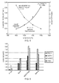
Figure 5 is a graph of evaporation rate of synthetic sea salt and Na2SO4-2%NaCl salt at different temperatures. -
Figure 6 is a graph of attack rate on different nickel superalloys in different oxidation testing conditions. -
Figure 7 is a graph of coating life for a platinum aluminide coating in different oxidation testing conditions. -
Figures 8(a) - 8(d) are micrographs showing the morphology of attack on CMSX4 after different oxidation testing conditions and CMSX4 after operation in a gas turbine engine. -
Figure 9 is a graph of temperature against time illustrating one cycle of the method of testing the oxidation resistance of an alloy according to the present disclosure. - A turbofan
gas turbine engine 10, as shown infigure 1 , comprises in flow series anintake 11, afan 12, anintermediate pressure compressor 13, ahigh pressure compressor 14, acombustion chamber 15, ahigh pressure turbine 16, anintermediate pressure turbine 17, alow pressure turbine 18 and anexhaust 19. Thehigh pressure turbine 16 is arranged to drive thehigh pressure compressor 14 via afirst shaft 26. Theintermediate pressure turbine 17 is arranged to drive theintermediate pressure compressor 13 via asecond shaft 28 and thelow pressure turbine 18 is arranged to drive thefan 12 via athird shaft 30. In operation air flows into theintake 11 and is compressed by thefan 12. A first portion of the air flows through, and is compressed by, theintermediate pressure compressor 13 and thehigh pressure compressor 14 and is supplied to thecombustion chamber 15. Fuel is injected into thecombustion chamber 15 and is burnt in the air to produce hot exhaust gases which flow through, and drive, thehigh pressure turbine 16, theintermediate pressure turbine 17 and thelow pressure turbine 18. The hot exhaust gases leaving thelow pressure turbine 18 flow through theexhaust 19 to provide propulsive thrust. A second portion of the air bypasses the main engine to provide propulsive thrust. - The
high pressure turbine 16 comprises aturbine disc 38 and a plurality ofturbine blades 40. Theturbine disc 38 comprises a plurality of axially extending circumferentially spaced slots in the radially outer periphery and eachturbine blade 40 locates in a respective one of the slots in the periphery of theturbine disc 38. One of theturbine blades 40 is shown infigure 2 . Theturbine blade 40 comprises aroot 42, ashank 44, aplatform 46 and anaerofoil 48. Theroot 42 is shaped to locate in the slot in the periphery of theturbine disc 38 and in this example theroot 42 is firtree shaped, but may be dovetail shaped. Theturbine blade 40 consists of a superalloy and the superalloy may be a nickel superalloy, a cobalt superalloy or an iron superalloy. The nickel superalloy may be a single crystal nickel superalloy and may comprise one or more of rhenium, ruthenium, yttrium and lanthanum. In this example the superalloy is a nickel superalloy and is a single crystal nickel superalloy, e.g. CMSX4. Theaerofoil 48 andplatform 46 of theturbine blade 40 may be provided with a protective coating, or a bond coating and a thermal barrier coating. The bond coating may be a protective coating.Figure 3 shows aprotective coating 50 on theouter surface 49 of theaerofoil 48 of theturbine blade 40. Theprotective coating 50 may be oxidation resistant and/or corrosion resistant. Theprotective coating 50 consists of a suitable coating alloy and the coating alloy may be an MCrAlY, a platinum coating, an aluminide coating, a platinum aluminide coating, a chromium aluminide, platinum chromium aluminide coating, a silicide aluminide coating or a platinum silicide aluminide coating. An MCrAlY consists of chromium, aluminium and yttrium and one or more of nickel, cobalt and iron, as is well known to those skilled in the art. The MCrAlY coating is deposited by plasma spraying, thermal spraying or electron beam physical vapour deposition - (EBPVD). The aluminide type coatings are generally deposited by chemical vapour deposition. The aluminide silicide coatings may be deposited by slurry deposition. The platinum may be deposited by plating, e.g. electroplating, and the chromium may be deposited by plating or chemical vapour deposition.
- A method of testing the oxidation resistance of an alloy is shown in
figure 4 . The method of testing the oxidation resistance of analloy 51 comprises weighing the alloy atstep 52 to determine the initial weight of the alloy, applying a layer of salt on the surface of the alloy atstep 54, then placing the alloy in a furnace instep 56 and the furnace is at a predetermined temperature of at least 1000°C and contains an oxygen containing gas e.g. air. The alloy is maintained in the furnace at the predetermined temperature for a predetermined period of time instep 58 and then the alloy is removed from the furnace and allowed to cool to ambient temperature, or other suitable temperature, atstep 60.Step 52 may also include measuring the dimension, or dimensions, e.g. diameter, or width and thickness, of the alloy. - After the alloy has cooled to ambient temperature, or other suitable temperature, steps 54 to 60 are repeated for a first predetermined number of times, as shown by the repeat path, or loop, A. After the alloy has been through
steps 54 to 60 for the first predetermined number of times the resistance to oxidation test is stopped, as shown by path C, andstep 62. When the oxidation resistance test is stopped the alloy is weighed to determine the final weight of the alloy atstep 64. -
Figure 9 shows the temperature and time ofsteps step 58 and the alloy is cooled to ambient temperature of 293K, 20°C, atstep 60.Figure 9 shows that the alloy is heated in the furnace from ambient temperature to 1273K during a heating time, then maintained in the furnace at the temperature of 1273K during a hot dwell time where T > 0.97 Tdwell.Figure 9 shows that the alloy is cooled from 1273K to ambient temperature, or other suitable temperature, over a cooling time and then is maintained at ambient temperature, or other suitable temperature, for a cold dwell time where T < 323K, 50°C. The other suitable temperature is preferably less than 323K, 50°C. - The alloy is periodically weighed after each of a second predetermined number of times that steps 54 to 60 have been repeated, as shown by path B, at
step 66 and the second predetermined number of times is less than the first predetermined number of times. The alloy is periodically weighed atstep step 66 and then steps 54 to 60 are repeated for the next second predetermined number of times. Again after the alloy has been cycled through the furnace for the next second predetermined number of times the alloy is weighed again instep 66 and then steps 54 to 60 are repeated. - The total weight loss of the alloy during the testing is determined at
step 68 by subtracting the measured weight of the alloy at the end of the test atstep 64 from the measured weight of the alloy before the test atstep 52. - The alloy is cut into two, or sectioned, in
step 70, and then the dimension of a first portion of the alloy which has been oxidised, the dimension of a second portion of the alloy which has been depleted of strengthening elements, e.g. aluminium, and the dimension of a third portion of the alloy which has not been oxidised or been depleted of strengthening elements are determined instep 72. The first portion of the alloy which has not been oxidised or been depleted of strengthening elements corresponds to a portion of the alloy which has not had its material properties affected by oxidation. The dimension of the first portion of the alloy which has been oxidised, the dimension of the second portion of the alloy which has been depleted of strengthening elements, e.g. aluminium, and the dimension of the third portion of the alloy which has not been oxidised or been depleted of strengthening elements, e.g. aluminium, are measured instep 72. - The total loss of usable dimension of the alloy during the testing is determined in step 74 by subtracting the determined dimension of the third portion of the alloy at the end of the test from the measured dimension of the alloy before the test.
- The total weight loss of the alloy during the test is correlated with the total loss of usable dimension of the alloy during the test in
step 76. - The total loss of usable dimension, or usable section, is a key parameter along with the time and the temperature for predicting oxidation attack in gas turbine engine turbine and combustion chamber components.
- The amount of salt applied to the surface of the alloy and the frequency of application of the salt is selected so that the salt is applied to the surface of the alloy at a level of 0.5 to 30µg cm-2 h-1. The salt is only present on the surface of the alloy for a brief period of time because it is quickly evaporated once it is placed in the furnace. An important factor in the method of testing the oxidation resistance of an alloy, cyclic oxidation testing, is the salt flux, the salt flux is controlled in order to balance the formation of a protective oxide scale, e.g. alumina, on the alloy, superalloy or coating alloy, with the effect of the salt in disrupting the formation of the protective oxide scale in order to maintain a degradation mechanism which reproduces the degradation mechanism of that for an alloy used for a component of a gas turbine engine or that for a coating alloy for a component of a gas turbine engine. If the salt flux level is below 0.5µg cm-2 h-1 the salt flux level is insufficient to disrupt the formation of the protective oxide scale and a degradation mechanism which reproduces the degradation mechanism for a component or a coating on a component in a gas turbine engine is not obtained, e.g. it is effectively the same as the conventional oxidation resistance testing. If the salt flux level is above 30µg cm-2 h-1 the salt level is too high and the formation of the protective oxide scale is disrupted to too high a level and again a degradation mechanism which reproduces the degradation mechanism for a component or a coating on a component in a gas turbine engine is not obtained.
- We have investigated the effect of the salt flux and have found that ranges of salt flux of between 0.5µg cm-2 h-1 and 30µg cm-2 h-1 are required. A preferred range of salt flux is 1µg cm-2 h-1 to 20µg cm-2 h-1. A more preferred range of salt flux is 7µg cm-2 h-1 to 15µg cm-2 h-1. Particular examples of salt flux are 7µg cm-2 h-1 and 15µg cm-2 h-1. Selection of the appropriate amount of salt for a cycling oxidation test depends upon the particular environment in which the gas turbine engine operates. A standard range of salt fluxes and salt chemistries may be used to assess the protection mechanisms of new alloys, whether superalloys or coating alloys. The salt flux (F) is determined by dividing the mass or weight of salt (m) applied per unit area (a) by the dwell time (t) in the furnace multiplied by the number of cycles (n) before reapplication of the salt, e.g. F = (m/a)/(t x n). For example applying the salt to the surface of the alloy to give a surface coverage of 0.14mg cm-2 to 0.3mg cm-2 and reapplying the salt to the surface of the alloy every twenty 1 hour cycles gives a salt flux of 7µg cm-2 h-1 to 15µg cm-2 h-1.
- The layer of salt may be applied onto the surface of the alloy by spraying an aqueous solution of salt onto the surface of the alloy and in particular the aqueous solution of salt may be applied by spraying the aqueous solution of salt manually or semi-automatically. After the aqueous solution of salt has been deposited onto the surface of the alloy, the alloy may be heated to a suitable temperature, for example a temperature of at least 120°C, to quickly evaporate the water to deposit the layer of salt onto the surface of the alloy. In order to spray the salt solution onto the surface of the alloy, the alloy is completely removed from the furnace and the salt solution is sprayed onto the alloy. The salt solution may be applied while the alloy is cooling to ambient temperature or after it has cooled down to ambient temperature, been weighed and reheated to a temperature of at least 120°C. The alloy is weighed after the salt has been applied, and after evaporation of the water to ensure that the required amount of salt has been applied to the alloy.
- Alternatively the layer of salt may be applied onto the surface of the alloy by providing a mist of an aqueous solution of salt and placing the alloy in the salt solution mist so that the mist deposits onto the surface of the alloy. In order to place the alloy in the salt solution mist, the alloy is removed from the furnace and placed in an anti-chamber adjacent the furnace, where the alloy is allowed to cool. The alloy is moved from the furnace to the anti-chamber by a sample holder. The salt solution mist is provided in the anti-chamber for a short period of time just before the alloy is removed from the furnace into the anti-chamber. When the alloy is moved from the furnace into the anti-chamber it is completely covered in a very thin layer of salt. The salt solution is thus applied while the alloy is cooling to ambient temperature.
- It is preferred that the salt is applied uniformly, e.g. a layer of uniform thickness, onto the surface of the alloy sample in order to prevent any preferential localised attack of the alloy surface by the salt due to variation in thickness of the layer of salt. It is necessary to calibrate the salt spray apparatus at known conditions, e.g. alloy composition, temperature, salt composition and salt flux, before testing any new alloy.
- The oxygen containing gas is generally air. The oxygen containing gas may comprise one or more of sulphur dioxide, sulphur trioxide and hydrogen chloride to simulate other corrosive species which may be present in a real life gas turbine engine.
- The salt used in the method of testing the oxidation resistance of an alloy, cyclic oxidation testing, generally comprises salt, sodium chloride, or sea salt, sodium chloride plus impurities. However, the salt may comprise a salt of one or more of the elements sodium, potassium, magnesium, calcium, vanadium, sulphur and chlorine. The salt may also be sodium sulphate and sodium chloride, e.g. Na2SO4 - 2% NaCl.
- The method of testing the oxidation resistance of an alloy, cyclic oxidation testing, may be to test the alloy at temperatures in the range of 1000°C to 1300°C. The method of testing the oxidation resistance of an alloy, cyclic oxidation testing, may be to test the alloy at a temperature greater than or equal to 1100°C. The method of testing the oxidation resistance of an alloy, cyclic oxidation testing, may be to test the alloy at a temperature greater than or equal to 1150°C. The temperature in the furnace is maintained substantially constant during the testing. The temperature in the furnace is monitored by one or more temperature sensors and the temperature measurements are supplied from the one or more temperatures sensors to a controller. The controller monitors the temperature measurements supplied by the one or more temperature sensors and variations in the temperature in the furnace are detected by the controller and the controller controls the furnace heater, or furnace heaters, so that variations in the temperature in the furnace is limited to 5°C or less.
- The alloy may be maintained in the furnace at the predetermined temperature for example for 15 minutes, 30 minutes or 1 hour or other suitable time period. The alloy may be weighed after every 20 cycles or after other suitable number of cycles. The first predetermined number of times, the total number of cycles, may be up to several hundred or thousands of cycles depending upon the length of the predetermined period of time that the alloy is maintained in the furnace.
- For example the alloy may be maintained in the furnace for a period of an hour and the alloy may be weighed every 20 cycles and there may be a hundred or several hundred cycles.
- The alloy is generally a sample of the alloy, whether a superalloy or a coating alloy. The sample may vary in size and may take the form of a small pin, a small disc, a rectangular plate, a small cotton reel, a short cylinder or a long bar of the superalloy or a small pin, a small disc, a rectangular plate, a small cotton reel, a short cylinder or a long bar with a coating of the coating alloy. The alloy may be a larger sample, an actual superalloy component or an actual component with a coating of the coating alloy.
- The samples may be cut and/or machined to shape and size but care should be taken to avoid excessive heating and deformation of the alloy sample to ensure that there is no recrystallization of the alloy. The surface of the samples are prepared and cleaned before testing.
- The attack morphology of samples of alloy tested for oxidation resistance according to the present disclosure, e.g. in the presence of salt, as described above is very consistent with that observed by actual components, consisting of the same alloy, experiencing engine conditions. In tests a platinum aluminide coating was produced on CMSX4 nickel superalloy samples and some of the samples were tested for oxidation resistance using conventional burner rig testing, some of the samples were tested for oxidation resistance in a furnace using conventional cyclic oxidation testing and some of the samples were tested for oxidation resistance using the cyclic oxidation testing according to the present disclosure. The morphology of the attack on these samples is shown in
figure 8. Figure 8 (a) shows a sample tested for oxidation resistance according to the present disclosure,figure 8 (c) shows a sample tested for oxidation resistance using a conventional burner rig andfigure 8 (d) shows a sample tested for oxidation resistance using conventional cyclic oxidation.Figure 8 (b) shows a comparative sample of a CMSX4 nickel superalloy turbine blade with a platinum aluminide coating which has been run in a gas turbine engine. The progression of attack along the grain boundaries of the aluminium rich phase of the platinum aluminide coating is clearly shown infigures 8 (a), 8 (b) and 8 (c) . However, the conventional cyclic oxidation test is distinctly different, as seen infigure 8 (d) and the platinum aluminide coating has formed a continuous protective alumina scale with no sign of any attack along the aluminium rich phase grain boundaries. - The test for oxidation resistance according to the present disclosure has been developed following an extensive study on the degradation kinetics and mechanisms of a range of superalloys, especially high temperature nickel superalloys, and coating alloys. The damage mechanisms of a range of alloy samples, superalloys and coating alloys, subject to conventional cyclic oxidation testing in air and conventional burner rig testing have been studied in conjunction with the damage morphology of turbine components, e.g. turbine blades and turbine vanes, that have run in a gas turbine engine.
- Surprisingly, during the study it was found that at temperatures of 1000° and above alloys, superalloys and coating alloys, are very sensitive to the presence of small amounts of salt even though salt has a very low dwell time on the surface of the alloys at these temperatures, due to the fast evaporation of the salt. This finding is in contrast to the previous view that salt would have very little effect on the alloys at temperatures above 1000°C because the salt evaporates rapidly. In tests the evaporation rate of synthetic sea salt at temperatures in the range of 1000°C to 1150°C and the evaporation rate of Na2SO4 - NaCl at 1100°C were measured by monitoring the mass change of salt deposited uniformly on an inert alumina sheet, with a thickness of 1 mm, using Thermo Gravimetric Analysis (TGA). The evaporation rate, in mg cm-2 s-1, of both of these salt mixtures at various temperatures is shown in
figure 5 and this shows that both of the salt mixtures evaporate very rapidly at temperatures of 1000°C and above and the evaporation rate increases exponentially with temperature.Figure 5 also shows the absolute half-life, (dwell time) of the sea salt on the surface of the inert alumina sheet. It is clear fromfigure 5 that a sea salt deposit of 0.14mg cm-2 may stay on the inert alumina sheet for up to 10 seconds at a temperature of 1000°C and for 1 second at a temperature of 1150°C before it evaporates. - Surprisingly, during the study it was found that even though the salt has a short dwell time on the surface of the alloy, superalloy or coating alloy, the salt had a significant effect on the oxidation of the alloy, superalloy or coating alloy.
- In a series of tests samples of four different nickel superalloys were tested for oxidation resistance using four different oxidation resistance testing techniques. The four nickel superalloys tested were CMSX4, CMSX10 (RR3010), MarM002 and C1023. The four oxidation resistance testing techniques were conventional burner rig testing, conventional cyclic oxidation resistance testing in air, oxidation resistance testing using sea salt according to the present disclosure and oxidation resistance testing using Na2SO4 - 2%NaCl according to the present disclosure and all the tests were conducted at a temperature of 1150°C.
Figure 6 shows the results of the testing and shows the attack rate in µm h-1 for the different alloys under the different oxidation resistance testing techniques. The total test time for each of the conventional burner rig testing, oxidation resistance testing using sea salt according to the present disclosure and oxidation resistance testing using Na2SO4 - 2%NaCl according to the present disclosure was less than 80 hours. The total test time for the conventional cyclic oxidation resistance testing in air was 600 hours. These tests demonstrate that the oxidation resistance testing according to the present disclosure can substantially reduce the amount of time to conduct the oxidation resistance testing. - In
figure 6 the conventional cyclic oxidation resistance testing in air did not involve the application of salt to the four nickel superalloys tested. The oxidation resistance testing using sea salt involved the application of 0.3mg cm-2 of salt every 20 cycles resulting in 15µg cm-2 h-1 to the four nickel superalloys tested. Similarly, the oxidation resistance testing using Na2SO4 - 2%NaCl involved the application of 0.3mg cm-2 of salt every 20 cycles resulting in 15µg cm-2 h-1 to the four nickel superalloys tested. The conventional burner rig testing involved a continuous supply of salt at 0.4ppm to the four nickel superalloys tested. All of these tests involved a dwell time of 1 hour in the furnace, except for the conventional burner rig testing which involved a dwell time of 15 minutes at the maximum temperature. - In another series of oxidation resistance tests a platinum aluminide coating was applied to samples of a nickel superalloy and the platinum aluminide coating was tested for oxidation resistance using four different oxidation resistance testing techniques. The nickel superalloy samples tested were CMSX4. The four oxidation resistance testing techniques were conventional burner rig testing, conventional cyclic oxidation resistance testing in air, oxidation resistance testing using sea salt according to the present disclosure and oxidation resistance testing using Na2SO4 - 2%NaCl according to the present disclosure and all the tests were conducted at a temperature of 1150°C.
Figure 7 shows the results of the testing and shows the coating life in hours for the platinum aluminide coating under the different oxidation resistance testing techniques. The coating life of the platinum aluminide coating using the conventional cyclic oxidation resistance testing in air was about 850 hours. The coating life of the platinum aluminide coating using the conventional burner rig testing was about 40 hours. The coating life of the platinum aluminide coating using oxidation resistance testing using sea salt according to the present disclosure was about 100 hours and the coating life of the platinum aluminide coating using oxidation resistance testing using Na2SO4-2%NaCl according to the present disclosure was about 75 hours. The conventional cyclic oxidation resistance testing, the oxidation resistance testing using sea salt and the oxidation resistance testing using Na2SO4 - 2%NaCl used a dwell time at the maximum temperature of 60 minutes exposure. The conventional burner rig testing used a higher cycle frequency with a dwell time at the maximum temperature of 15 minutes exposure. These tests demonstrate that the oxidation resistance testing according to the present disclosure can substantially reduce the amount of time to conduct the oxidation resistance testing. - In
figure 7 the conventional cyclic oxidation resistance testing in air did not involve the application of salt to the platinum aluminide coating tested. The oxidation resistance testing using sea salt involved the application of 0.14mg cm-2 of salt every 20 cycles resulting in 7µg cm-2 h-1 to the platinum aluminide coating. Similarly, the oxidation resistance testing using Na2SO4 - 2%NaCl involved the application of 0.14mg cm-2 of salt every 20 cycles resulting in 7µg cm-2 h-1 to the platinum aluminide coating. The conventional burner rig testing involved a continuous supply of salt at 0.4ppm to the platinum aluminide coating. All of these tests involved a dwell time of 1 hour in the furnace, except for the conventional burner rig testing which involved a dwell time of 15 minutes at the maximum temperature. - In similar tests carried out on nickel superalloy CMSX4 coated with a diffused platinum coating, nickel superalloy CMSX4 coated with a vapour aluminised aluminide coating and nickel superalloy CMSX4 coated with a pack aluminised aluminide coating a similar trend to the platinum aluminide coating was observed, e.g. the use of salt in the oxidation resistance testing significantly reduces the amount of time to conduct the oxidation resistance testing.
- It is expected that the test is suitable for testing the oxidation resistance of overlay coatings, e.g. MCrAlY coatings. The MCrAlY coatings may be deposited by plasma spraying, thermal spraying or physical vapour deposition, e.g. electron beam physical vapour deposition. The aluminide coatings, e.g. a simple aluminide, a chromium aluminide, a platinum aluminide, platinum chromium aluminide or a silicide aluminide may be deposited by chemical vapour deposition. The chromium and/or platinum may be deposited by plating, electroplating or chemical vapour deposition.
- The advantage of testing the oxidation resistance of an alloy according to the present disclosure is that it reproduces the degradation observed in real gas turbine engine components, or components of other engines operating at high temperatures, internal combustion engines, e.g. diesel engines, petrol engines, or combustion chambers, furnaces, ovens etc. Another advantage of testing the oxidation resistance of an alloy according to the present disclosure is that it significantly reduces the time taken to test the alloy compared to conventional cyclic oxidation testing. A further advantage of testing the oxidation resistance of an alloy according to the present disclosure is it controls the temperature with a high degree of accuracy. Additional advantages are that testing the oxidation resistance of an alloy according to the present disclosure is safer than burner rig testing, has reduced cost compared to burner rig testing and has reduced environmental pollution compared to burner rig testing.
Claims (16)
- A method of testing the oxidation resistance of an alloy comprising the steps of:-a) applying a layer of salt on the surface of the alloy (52),b) placing the alloy in a furnace (54), the furnace being at a predetermined temperature of at least 1000°C and containing an oxygen containing gas,c) maintaining the alloy in the furnace (56) at the predetermined temperature for a predetermined period of time,d) removing the alloy from the furnace and allowing the alloy to cool to ambient temperature or other suitable temperature,e) repeating steps a) to d) for a first predetermined number of times such that the salt is applied to the surface of the alloy at a level of 0.5 to 30µg cm-2 h-1, andf) weighing the alloy periodically to determine the oxidation resistance of the alloy, comprising at least weighing the alloy before the test and weighing the alloy at the end of the test.
- A method as claimed in claim 1 wherein step a) comprises applying the layer of salt by spraying an aqueous solution of salt onto the surface of the alloy or by providing a mist of an aqueous solution of salt and placing the alloy in the mist so that the mist deposits onto the surface of the alloy.
- A method as claimed in claim 2 wherein step a) comprises heating the alloy to a temperature of at least 120°C to evaporate the water to deposit the salt onto the surface of the alloy.
- A method as claimed in any of claims 1 to 3 wherein step d) comprises cooling the alloy to ambient, or other suitable, temperature.
- A method as claimed in any of claims 1 to 4 wherein the oxygen containing gas comprises air.
- A method as claimed in any of claims 1 to 5 comprising applying the salt to the surface of the alloy at a level of 1 to 20µg cm-2 h-1.
- A method as claimed in any of claims 1 to 6 wherein the salt comprises a salt of one or more of the elements sodium, potassium, magnesium, calcium, vanadium, sulphur and chlorine.
- A method as claimed in any of claims 1 to 7 wherein the predetermined temperature is up to 1300°C.
- A method as claimed in any of claims 1 to 8 wherein step f) comprises weighing the alloy (66) every time steps a) to d) have been repeated a number of times.
- A method as claimed in any of claims 1 to 9 wherein the alloy is a superalloy or a coating alloy.
- A method as claimed in claim 10 wherein the superalloy is a nickel superalloy, a single crystal nickel superalloy, a cobalt superalloy or an iron superalloy.
- A method as claimed in claim 10 wherein the coating alloy is an MCrAlY, a platinum coating, an aluminide coating, a platinum aluminide coating, a chromium aluminide, platinum chromium aluminide coating, a silicide aluminide coating or a platinum silicide aluminide coating.
- A method as claimed in any of claims 1 to 12 comprising determining the total weight loss of the alloy during the testing (68) by subtracting the measured weight of the alloy at the end of the test (64) from the measured weight of the alloy before the test (52).
- A method as claimed in any of claims 1 to 13 including the further steps of g) cutting the alloy into two (70) and step h) determining the dimension of a first portion of the alloy which has been oxidised, the dimension of a second portion of the alloy which has been depleted of strengthening elements and the dimension of a third portion of the alloy which has not been oxidised or been depleted of strengthening elements (72).
- A method as claimed in claim 14 comprising determining the total loss of usable dimension of the alloy during the testing (74) by subtracting the determined dimension of the third portion of the alloy at the end of the test from the measured dimension of the alloy before the test.
- A method as claimed in claim 15 further including the step of i) correlating the total weight loss of the alloy during the test with the total loss of usable dimension of the alloy during the test (76).
Applications Claiming Priority (1)
| Application Number | Priority Date | Filing Date | Title |
|---|---|---|---|
| GBGB1407151.8A GB201407151D0 (en) | 2014-04-23 | 2014-04-23 | A method of testing the oxidation resistance of an alloy |
Publications (2)
| Publication Number | Publication Date |
|---|---|
| EP2937684A1 true EP2937684A1 (en) | 2015-10-28 |
| EP2937684B1 EP2937684B1 (en) | 2022-12-14 |
Family
ID=50929078
Family Applications (1)
| Application Number | Title | Priority Date | Filing Date |
|---|---|---|---|
| EP15164188.3A Active EP2937684B1 (en) | 2014-04-23 | 2015-04-20 | A method of testing the oxidation resistance of an alloy |
Country Status (3)
| Country | Link |
|---|---|
| US (1) | US9752970B2 (en) |
| EP (1) | EP2937684B1 (en) |
| GB (1) | GB201407151D0 (en) |
Families Citing this family (4)
| Publication number | Priority date | Publication date | Assignee | Title |
|---|---|---|---|---|
| CN110806376A (en) * | 2018-08-06 | 2020-02-18 | 宝钢特钢有限公司 | Corrosion evaluation method for nickel-based alloy strip for electric heating pipe of water heater |
| CN110487788B (en) * | 2019-07-12 | 2021-08-20 | 中国科学院金属研究所 | A method for evaluating the propensity to form small-angle grain boundaries in single-crystal superalloys |
| US11686208B2 (en) | 2020-02-06 | 2023-06-27 | Rolls-Royce Corporation | Abrasive coating for high-temperature mechanical systems |
| US20230266012A1 (en) * | 2022-02-18 | 2023-08-24 | General Electric Company | Mixer assembly with a catalytic metal coating for a gas turbine engine |
Citations (1)
| Publication number | Priority date | Publication date | Assignee | Title |
|---|---|---|---|---|
| US5916382A (en) * | 1992-03-09 | 1999-06-29 | Hitachi, Ltd. | High corrosion resistant high strength superalloy and gas turbine utilizing the alloy |
Family Cites Families (16)
| Publication number | Priority date | Publication date | Assignee | Title |
|---|---|---|---|---|
| US3418111A (en) * | 1966-10-27 | 1968-12-24 | Union Carbide Corp | Cobalt base alloy |
| US5455119A (en) | 1993-11-08 | 1995-10-03 | Praxair S.T. Technology, Inc. | Coating composition having good corrosion and oxidation resistance |
| GB9903988D0 (en) | 1999-02-22 | 1999-10-20 | Rolls Royce Plc | A nickel based superalloy |
| EP1094131B1 (en) | 1999-10-23 | 2004-05-06 | ROLLS-ROYCE plc | A corrosion protective coating for a metallic article and a method of applying a corrosion protective coating to a metallic article |
| US6352670B1 (en) * | 2000-08-18 | 2002-03-05 | Ati Properties, Inc. | Oxidation and corrosion resistant austenitic stainless steel including molybdenum |
| US20040200549A1 (en) * | 2002-12-10 | 2004-10-14 | Cetel Alan D. | High strength, hot corrosion and oxidation resistant, equiaxed nickel base superalloy and articles and method of making |
| JP2006515535A (en) * | 2002-12-23 | 2006-06-01 | アプライド シン フィルムズ,インコーポレイティッド | Aluminum phosphate coating |
| US6983599B2 (en) * | 2004-02-12 | 2006-01-10 | General Electric Company | Combustor member and method for making a combustor assembly |
| GB0513121D0 (en) | 2005-06-28 | 2005-10-26 | Rolls Royce Plc | A nickel based superalloy |
| JP5344453B2 (en) | 2005-09-27 | 2013-11-20 | 独立行政法人物質・材料研究機構 | Ni-base superalloy with excellent oxidation resistance |
| KR100747170B1 (en) | 2006-05-12 | 2007-08-07 | 현대자동차주식회사 | High Temperature Oxidation Test Method of Heat-resistant Materials for Exhaust Systems |
| KR101008182B1 (en) | 2008-12-23 | 2011-01-13 | 재단법인 포항산업과학연구원 | Apparatus for evaluating thermal shock and cyclic oxidation of refractory |
| CN101900663B (en) * | 2009-05-27 | 2013-05-15 | 宝山钢铁股份有限公司 | High-temperature cyclic oxidation corrosion simulating test device |
| CN102094163B (en) * | 2011-02-25 | 2012-09-05 | 中国科学院金属研究所 | CoNiCrAlY corrosion-resistant thermal spraying alloy powder and preparation method thereof |
| WO2012142422A1 (en) | 2011-04-13 | 2012-10-18 | Rolls-Royce Corporation | Interfacial diffusion barrier layer including iridium on a metallic substrate |
| JP2013134162A (en) * | 2011-12-27 | 2013-07-08 | Hitachi Ltd | Atmospheric corrosion testing method and atmospheric corrosion testing apparatus |
-
2014
- 2014-04-23 GB GBGB1407151.8A patent/GB201407151D0/en not_active Ceased
-
2015
- 2015-04-20 US US14/690,965 patent/US9752970B2/en active Active
- 2015-04-20 EP EP15164188.3A patent/EP2937684B1/en active Active
Patent Citations (1)
| Publication number | Priority date | Publication date | Assignee | Title |
|---|---|---|---|---|
| US5916382A (en) * | 1992-03-09 | 1999-06-29 | Hitachi, Ltd. | High corrosion resistant high strength superalloy and gas turbine utilizing the alloy |
Non-Patent Citations (3)
| Title |
|---|
| SUDHANGSHU BOSE: "High Temperature Coatings", 1 January 2007, BUTTERWORTH-HEINEMANN, ISBN: 978-0-7506-8252-7, XP040426160 * |
| WANG F ET AL: "Oxidation and hot corrosion behavior of sputtered nanocrystalline coating of superalloy K52", THIN SOLID FILMS, ELSEVIER-SEQUOIA S.A. LAUSANNE, CH, vol. 516, no. 16, 30 June 2008 (2008-06-30), pages 5740 - 5747, XP023904299, ISSN: 0040-6090, [retrieved on 20080630], DOI: 10.1016/J.TSF.2007.07.131 * |
| ZHENHUA DAN ET AL: "Effects of environmental factors on atmospheric corrosion of aluminium and its alloys under constant dew point conditions", CORROSION SCIENCE, OXFORD, GB, vol. 57, 27 December 2011 (2011-12-27), pages 22 - 29, XP028458277, ISSN: 0010-938X, [retrieved on 20120105], DOI: 10.1016/J.CORSCI.2011.12.038 * |
Also Published As
| Publication number | Publication date |
|---|---|
| GB201407151D0 (en) | 2014-06-04 |
| US20150308937A1 (en) | 2015-10-29 |
| US9752970B2 (en) | 2017-09-05 |
| EP2937684B1 (en) | 2022-12-14 |
Similar Documents
| Publication | Publication Date | Title |
|---|---|---|
| Lau et al. | Influence of bondcoat pre-treatment and surface topology on the lifetime of EB-PVD TBCs | |
| Kim et al. | The effect of the type of thermal exposure on the durability of thermal barrier coatings | |
| US9752970B2 (en) | Method of testing the oxidation resistance of an alloy | |
| US6339879B1 (en) | Method of sizing and forming a cooling hole in a gas turbine engine component | |
| Cormier | Thermal cycling creep resistance of Ni-based single crystal superalloys | |
| EP2405032B1 (en) | Oxidation and corrosion resistant coating | |
| Warnes | Improved aluminide/MCrAlX coating systems for super alloys using CVD low activity aluminizing | |
| CN110132826A (en) | The test method of nickel-base high-temperature single crystal alloy hot corrosion resistance | |
| US8252601B2 (en) | Method for designating a component having a heat insulation layer and for determining its operating time | |
| Getsov et al. | Sulfide oxide corrosion of modern heat-resistant alloys | |
| Encinas-Oropesa et al. | Evaluation of oxidation related damage caused to a gas turbine disc alloy between 700 and 800 C | |
| Leyens et al. | Effect of experimental procedures on the cyclic, hot-corrosion behavior of NiCoCrAlY-type bondcoat alloys | |
| Srinivasan et al. | Degradation of MCrAlY Coating and substrate superalloy during long term thermal exposure | |
| EP1426759A1 (en) | A non-destructive testing method of determining the depletion of a coating | |
| Leyens et al. | Significance of Experimental Procedures on the Hot Corrosion Behaviour of Nickel-Base Alloys under Cyclic Conditions | |
| Shifler | High-temperature gaseous corrosion testing | |
| Chan et al. | Degradation mechanism characterization and remaining life prediction for NiCoCrAlY coatings | |
| Bacos et al. | ALLBATROS advanced long life blade turbine coating systems | |
| Deodeshmukh | Evaluating the hot corrosion behavior of high-temperature alloys for gas turbine engine components | |
| US20070059550A1 (en) | Nickel based superalloy | |
| JP4986730B2 (en) | Judgment method for coating deterioration of high temperature metal products | |
| Santhanam et al. | The influence of protective coatings on thermal fatigue resistance of Udimet 710 | |
| Schmidt et al. | Influence of bond coat roughness on life time of APS thermal barrier coating systems under thermo-mechanical load | |
| Nalin | Degradation of environmental protection coatings for gas turbine materials | |
| Chmiela et al. | Degradation of Si-Al aluminide coating after service of turbine blades made of ZhS6K superalloy |
Legal Events
| Date | Code | Title | Description |
|---|---|---|---|
| PUAI | Public reference made under article 153(3) epc to a published international application that has entered the european phase |
Free format text: ORIGINAL CODE: 0009012 |
|
| AK | Designated contracting states |
Kind code of ref document: A1 Designated state(s): AL AT BE BG CH CY CZ DE DK EE ES FI FR GB GR HR HU IE IS IT LI LT LU LV MC MK MT NL NO PL PT RO RS SE SI SK SM TR |
|
| AX | Request for extension of the european patent |
Extension state: BA ME |
|
| 17P | Request for examination filed |
Effective date: 20160330 |
|
| RBV | Designated contracting states (corrected) |
Designated state(s): AL AT BE BG CH CY CZ DE DK EE ES FI FR GB GR HR HU IE IS IT LI LT LU LV MC MK MT NL NO PL PT RO RS SE SI SK SM TR |
|
| RAP1 | Party data changed (applicant data changed or rights of an application transferred) |
Owner name: THE CHANCELLOR, MASTERS AND SCHOLARS OF THE UNIVERSITY OF CAMBRIDGE Owner name: ROLLS-ROYCE PLC |
|
| STAA | Information on the status of an ep patent application or granted ep patent |
Free format text: STATUS: EXAMINATION IS IN PROGRESS |
|
| 17Q | First examination report despatched |
Effective date: 20200506 |
|
| REG | Reference to a national code |
Ref country code: DE Ref legal event code: R079 Ref document number: 602015081923 Country of ref document: DE Free format text: PREVIOUS MAIN CLASS: G01N0017000000 Ipc: G01N0005040000 |
|
| RIC1 | Information provided on ipc code assigned before grant |
Ipc: C22C 19/05 20060101ALI20220817BHEP Ipc: G01N 5/00 20060101ALI20220817BHEP Ipc: G01N 17/00 20060101ALI20220817BHEP Ipc: C22C 27/06 20060101ALI20220817BHEP Ipc: C22C 5/04 20060101ALI20220817BHEP Ipc: G01N 5/04 20060101AFI20220817BHEP |
|
| GRAP | Despatch of communication of intention to grant a patent |
Free format text: ORIGINAL CODE: EPIDOSNIGR1 |
|
| STAA | Information on the status of an ep patent application or granted ep patent |
Free format text: STATUS: GRANT OF PATENT IS INTENDED |
|
| INTG | Intention to grant announced |
Effective date: 20220930 |
|
| GRAS | Grant fee paid |
Free format text: ORIGINAL CODE: EPIDOSNIGR3 |
|
| GRAA | (expected) grant |
Free format text: ORIGINAL CODE: 0009210 |
|
| STAA | Information on the status of an ep patent application or granted ep patent |
Free format text: STATUS: THE PATENT HAS BEEN GRANTED |
|
| AK | Designated contracting states |
Kind code of ref document: B1 Designated state(s): AL AT BE BG CH CY CZ DE DK EE ES FI FR GB GR HR HU IE IS IT LI LT LU LV MC MK MT NL NO PL PT RO RS SE SI SK SM TR |
|
| REG | Reference to a national code |
Ref country code: GB Ref legal event code: FG4D |
|
| REG | Reference to a national code |
Ref country code: CH Ref legal event code: EP |
|
| REG | Reference to a national code |
Ref country code: DE Ref legal event code: R096 Ref document number: 602015081923 Country of ref document: DE |
|
| REG | Reference to a national code |
Ref country code: IE Ref legal event code: FG4D |
|
| REG | Reference to a national code |
Ref country code: AT Ref legal event code: REF Ref document number: 1537961 Country of ref document: AT Kind code of ref document: T Effective date: 20230115 |
|
| REG | Reference to a national code |
Ref country code: LT Ref legal event code: MG9D |
|
| REG | Reference to a national code |
Ref country code: NL Ref legal event code: MP Effective date: 20221214 |
|
| PG25 | Lapsed in a contracting state [announced via postgrant information from national office to epo] |
Ref country code: SE Free format text: LAPSE BECAUSE OF FAILURE TO SUBMIT A TRANSLATION OF THE DESCRIPTION OR TO PAY THE FEE WITHIN THE PRESCRIBED TIME-LIMIT Effective date: 20221214 Ref country code: NO Free format text: LAPSE BECAUSE OF FAILURE TO SUBMIT A TRANSLATION OF THE DESCRIPTION OR TO PAY THE FEE WITHIN THE PRESCRIBED TIME-LIMIT Effective date: 20230314 Ref country code: LT Free format text: LAPSE BECAUSE OF FAILURE TO SUBMIT A TRANSLATION OF THE DESCRIPTION OR TO PAY THE FEE WITHIN THE PRESCRIBED TIME-LIMIT Effective date: 20221214 Ref country code: FI Free format text: LAPSE BECAUSE OF FAILURE TO SUBMIT A TRANSLATION OF THE DESCRIPTION OR TO PAY THE FEE WITHIN THE PRESCRIBED TIME-LIMIT Effective date: 20221214 |
|
| REG | Reference to a national code |
Ref country code: AT Ref legal event code: MK05 Ref document number: 1537961 Country of ref document: AT Kind code of ref document: T Effective date: 20221214 |
|
| PG25 | Lapsed in a contracting state [announced via postgrant information from national office to epo] |
Ref country code: RS Free format text: LAPSE BECAUSE OF FAILURE TO SUBMIT A TRANSLATION OF THE DESCRIPTION OR TO PAY THE FEE WITHIN THE PRESCRIBED TIME-LIMIT Effective date: 20221214 Ref country code: LV Free format text: LAPSE BECAUSE OF FAILURE TO SUBMIT A TRANSLATION OF THE DESCRIPTION OR TO PAY THE FEE WITHIN THE PRESCRIBED TIME-LIMIT Effective date: 20221214 Ref country code: HR Free format text: LAPSE BECAUSE OF FAILURE TO SUBMIT A TRANSLATION OF THE DESCRIPTION OR TO PAY THE FEE WITHIN THE PRESCRIBED TIME-LIMIT Effective date: 20221214 Ref country code: GR Free format text: LAPSE BECAUSE OF FAILURE TO SUBMIT A TRANSLATION OF THE DESCRIPTION OR TO PAY THE FEE WITHIN THE PRESCRIBED TIME-LIMIT Effective date: 20230315 |
|
| PG25 | Lapsed in a contracting state [announced via postgrant information from national office to epo] |
Ref country code: NL Free format text: LAPSE BECAUSE OF FAILURE TO SUBMIT A TRANSLATION OF THE DESCRIPTION OR TO PAY THE FEE WITHIN THE PRESCRIBED TIME-LIMIT Effective date: 20221214 |
|
| P01 | Opt-out of the competence of the unified patent court (upc) registered |
Effective date: 20230528 |
|
| PG25 | Lapsed in a contracting state [announced via postgrant information from national office to epo] |
Ref country code: SM Free format text: LAPSE BECAUSE OF FAILURE TO SUBMIT A TRANSLATION OF THE DESCRIPTION OR TO PAY THE FEE WITHIN THE PRESCRIBED TIME-LIMIT Effective date: 20221214 Ref country code: RO Free format text: LAPSE BECAUSE OF FAILURE TO SUBMIT A TRANSLATION OF THE DESCRIPTION OR TO PAY THE FEE WITHIN THE PRESCRIBED TIME-LIMIT Effective date: 20221214 Ref country code: PT Free format text: LAPSE BECAUSE OF FAILURE TO SUBMIT A TRANSLATION OF THE DESCRIPTION OR TO PAY THE FEE WITHIN THE PRESCRIBED TIME-LIMIT Effective date: 20230414 Ref country code: ES Free format text: LAPSE BECAUSE OF FAILURE TO SUBMIT A TRANSLATION OF THE DESCRIPTION OR TO PAY THE FEE WITHIN THE PRESCRIBED TIME-LIMIT Effective date: 20221214 Ref country code: EE Free format text: LAPSE BECAUSE OF FAILURE TO SUBMIT A TRANSLATION OF THE DESCRIPTION OR TO PAY THE FEE WITHIN THE PRESCRIBED TIME-LIMIT Effective date: 20221214 Ref country code: CZ Free format text: LAPSE BECAUSE OF FAILURE TO SUBMIT A TRANSLATION OF THE DESCRIPTION OR TO PAY THE FEE WITHIN THE PRESCRIBED TIME-LIMIT Effective date: 20221214 Ref country code: AT Free format text: LAPSE BECAUSE OF FAILURE TO SUBMIT A TRANSLATION OF THE DESCRIPTION OR TO PAY THE FEE WITHIN THE PRESCRIBED TIME-LIMIT Effective date: 20221214 |
|
| PG25 | Lapsed in a contracting state [announced via postgrant information from national office to epo] |
Ref country code: SK Free format text: LAPSE BECAUSE OF FAILURE TO SUBMIT A TRANSLATION OF THE DESCRIPTION OR TO PAY THE FEE WITHIN THE PRESCRIBED TIME-LIMIT Effective date: 20221214 Ref country code: PL Free format text: LAPSE BECAUSE OF FAILURE TO SUBMIT A TRANSLATION OF THE DESCRIPTION OR TO PAY THE FEE WITHIN THE PRESCRIBED TIME-LIMIT Effective date: 20221214 Ref country code: IS Free format text: LAPSE BECAUSE OF FAILURE TO SUBMIT A TRANSLATION OF THE DESCRIPTION OR TO PAY THE FEE WITHIN THE PRESCRIBED TIME-LIMIT Effective date: 20230414 Ref country code: AL Free format text: LAPSE BECAUSE OF FAILURE TO SUBMIT A TRANSLATION OF THE DESCRIPTION OR TO PAY THE FEE WITHIN THE PRESCRIBED TIME-LIMIT Effective date: 20221214 |
|
| REG | Reference to a national code |
Ref country code: DE Ref legal event code: R097 Ref document number: 602015081923 Country of ref document: DE |
|
| PLBE | No opposition filed within time limit |
Free format text: ORIGINAL CODE: 0009261 |
|
| STAA | Information on the status of an ep patent application or granted ep patent |
Free format text: STATUS: NO OPPOSITION FILED WITHIN TIME LIMIT |
|
| PG25 | Lapsed in a contracting state [announced via postgrant information from national office to epo] |
Ref country code: DK Free format text: LAPSE BECAUSE OF FAILURE TO SUBMIT A TRANSLATION OF THE DESCRIPTION OR TO PAY THE FEE WITHIN THE PRESCRIBED TIME-LIMIT Effective date: 20221214 |
|
| 26N | No opposition filed |
Effective date: 20230915 |
|
| PG25 | Lapsed in a contracting state [announced via postgrant information from national office to epo] |
Ref country code: SI Free format text: LAPSE BECAUSE OF FAILURE TO SUBMIT A TRANSLATION OF THE DESCRIPTION OR TO PAY THE FEE WITHIN THE PRESCRIBED TIME-LIMIT Effective date: 20221214 |
|
| REG | Reference to a national code |
Ref country code: CH Ref legal event code: PL |
|
| PG25 | Lapsed in a contracting state [announced via postgrant information from national office to epo] |
Ref country code: LU Free format text: LAPSE BECAUSE OF NON-PAYMENT OF DUE FEES Effective date: 20230420 |
|
| REG | Reference to a national code |
Ref country code: BE Ref legal event code: MM Effective date: 20230430 |
|
| PG25 | Lapsed in a contracting state [announced via postgrant information from national office to epo] |
Ref country code: MC Free format text: LAPSE BECAUSE OF FAILURE TO SUBMIT A TRANSLATION OF THE DESCRIPTION OR TO PAY THE FEE WITHIN THE PRESCRIBED TIME-LIMIT Effective date: 20221214 |
|
| PG25 | Lapsed in a contracting state [announced via postgrant information from national office to epo] |
Ref country code: MC Free format text: LAPSE BECAUSE OF FAILURE TO SUBMIT A TRANSLATION OF THE DESCRIPTION OR TO PAY THE FEE WITHIN THE PRESCRIBED TIME-LIMIT Effective date: 20221214 Ref country code: LI Free format text: LAPSE BECAUSE OF NON-PAYMENT OF DUE FEES Effective date: 20230430 Ref country code: CH Free format text: LAPSE BECAUSE OF NON-PAYMENT OF DUE FEES Effective date: 20230430 |
|
| REG | Reference to a national code |
Ref country code: IE Ref legal event code: MM4A |
|
| PG25 | Lapsed in a contracting state [announced via postgrant information from national office to epo] |
Ref country code: BE Free format text: LAPSE BECAUSE OF NON-PAYMENT OF DUE FEES Effective date: 20230430 |
|
| PG25 | Lapsed in a contracting state [announced via postgrant information from national office to epo] |
Ref country code: IE Free format text: LAPSE BECAUSE OF NON-PAYMENT OF DUE FEES Effective date: 20230420 |
|
| PG25 | Lapsed in a contracting state [announced via postgrant information from national office to epo] |
Ref country code: IE Free format text: LAPSE BECAUSE OF NON-PAYMENT OF DUE FEES Effective date: 20230420 |
|
| PG25 | Lapsed in a contracting state [announced via postgrant information from national office to epo] |
Ref country code: IT Free format text: LAPSE BECAUSE OF FAILURE TO SUBMIT A TRANSLATION OF THE DESCRIPTION OR TO PAY THE FEE WITHIN THE PRESCRIBED TIME-LIMIT Effective date: 20221214 |
|
| PG25 | Lapsed in a contracting state [announced via postgrant information from national office to epo] |
Ref country code: BG Free format text: LAPSE BECAUSE OF FAILURE TO SUBMIT A TRANSLATION OF THE DESCRIPTION OR TO PAY THE FEE WITHIN THE PRESCRIBED TIME-LIMIT Effective date: 20221214 |
|
| PG25 | Lapsed in a contracting state [announced via postgrant information from national office to epo] |
Ref country code: BG Free format text: LAPSE BECAUSE OF FAILURE TO SUBMIT A TRANSLATION OF THE DESCRIPTION OR TO PAY THE FEE WITHIN THE PRESCRIBED TIME-LIMIT Effective date: 20221214 |
|
| PGFP | Annual fee paid to national office [announced via postgrant information from national office to epo] |
Ref country code: DE Payment date: 20250428 Year of fee payment: 11 |
|
| PGFP | Annual fee paid to national office [announced via postgrant information from national office to epo] |
Ref country code: FR Payment date: 20250424 Year of fee payment: 11 |
|
| PG25 | Lapsed in a contracting state [announced via postgrant information from national office to epo] |
Ref country code: CY Free format text: LAPSE BECAUSE OF FAILURE TO SUBMIT A TRANSLATION OF THE DESCRIPTION OR TO PAY THE FEE WITHIN THE PRESCRIBED TIME-LIMIT; INVALID AB INITIO Effective date: 20150420 |
|
| PG25 | Lapsed in a contracting state [announced via postgrant information from national office to epo] |
Ref country code: HU Free format text: LAPSE BECAUSE OF FAILURE TO SUBMIT A TRANSLATION OF THE DESCRIPTION OR TO PAY THE FEE WITHIN THE PRESCRIBED TIME-LIMIT; INVALID AB INITIO Effective date: 20150420 |
|
| PG25 | Lapsed in a contracting state [announced via postgrant information from national office to epo] |
Ref country code: TR Free format text: LAPSE BECAUSE OF FAILURE TO SUBMIT A TRANSLATION OF THE DESCRIPTION OR TO PAY THE FEE WITHIN THE PRESCRIBED TIME-LIMIT Effective date: 20221214 |
|
| PGFP | Annual fee paid to national office [announced via postgrant information from national office to epo] |
Ref country code: GB Payment date: 20260313 Year of fee payment: 12 |