EP2937582A1 - Floating bush bearing device and supercharger provided with same - Google Patents
Floating bush bearing device and supercharger provided with same Download PDFInfo
- Publication number
- EP2937582A1 EP2937582A1 EP12890467.9A EP12890467A EP2937582A1 EP 2937582 A1 EP2937582 A1 EP 2937582A1 EP 12890467 A EP12890467 A EP 12890467A EP 2937582 A1 EP2937582 A1 EP 2937582A1
- Authority
- EP
- European Patent Office
- Prior art keywords
- floating bush
- circumferential surface
- rotation shaft
- inner circumferential
- bush
- Prior art date
- Legal status (The legal status is an assumption and is not a legal conclusion. Google has not performed a legal analysis and makes no representation as to the accuracy of the status listed.)
- Granted
Links
Images


Classifications
-
- F—MECHANICAL ENGINEERING; LIGHTING; HEATING; WEAPONS; BLASTING
- F16—ENGINEERING ELEMENTS AND UNITS; GENERAL MEASURES FOR PRODUCING AND MAINTAINING EFFECTIVE FUNCTIONING OF MACHINES OR INSTALLATIONS; THERMAL INSULATION IN GENERAL
- F16C—SHAFTS; FLEXIBLE SHAFTS; ELEMENTS OR CRANKSHAFT MECHANISMS; ROTARY BODIES OTHER THAN GEARING ELEMENTS; BEARINGS
- F16C17/00—Sliding-contact bearings for exclusively rotary movement
- F16C17/02—Sliding-contact bearings for exclusively rotary movement for radial load only
- F16C17/028—Sliding-contact bearings for exclusively rotary movement for radial load only with fixed wedges to generate hydrodynamic pressure, e.g. multi-lobe bearings
-
- F—MECHANICAL ENGINEERING; LIGHTING; HEATING; WEAPONS; BLASTING
- F01—MACHINES OR ENGINES IN GENERAL; ENGINE PLANTS IN GENERAL; STEAM ENGINES
- F01D—NON-POSITIVE DISPLACEMENT MACHINES OR ENGINES, e.g. STEAM TURBINES
- F01D25/00—Component parts, details, or accessories, not provided for in, or of interest apart from, other groups
- F01D25/16—Arrangement of bearings; Supporting or mounting bearings in casings
- F01D25/166—Sliding contact bearing
-
- F—MECHANICAL ENGINEERING; LIGHTING; HEATING; WEAPONS; BLASTING
- F01—MACHINES OR ENGINES IN GENERAL; ENGINE PLANTS IN GENERAL; STEAM ENGINES
- F01D—NON-POSITIVE DISPLACEMENT MACHINES OR ENGINES, e.g. STEAM TURBINES
- F01D25/00—Component parts, details, or accessories, not provided for in, or of interest apart from, other groups
- F01D25/18—Lubricating arrangements
- F01D25/183—Sealing means
- F01D25/186—Sealing means for sliding contact bearing
-
- F—MECHANICAL ENGINEERING; LIGHTING; HEATING; WEAPONS; BLASTING
- F04—POSITIVE - DISPLACEMENT MACHINES FOR LIQUIDS; PUMPS FOR LIQUIDS OR ELASTIC FLUIDS
- F04D—NON-POSITIVE-DISPLACEMENT PUMPS
- F04D17/00—Radial-flow pumps, e.g. centrifugal pumps; Helico-centrifugal pumps
- F04D17/08—Centrifugal pumps
- F04D17/10—Centrifugal pumps for compressing or evacuating
-
- F—MECHANICAL ENGINEERING; LIGHTING; HEATING; WEAPONS; BLASTING
- F04—POSITIVE - DISPLACEMENT MACHINES FOR LIQUIDS; PUMPS FOR LIQUIDS OR ELASTIC FLUIDS
- F04D—NON-POSITIVE-DISPLACEMENT PUMPS
- F04D29/00—Details, component parts, or accessories
- F04D29/05—Shafts or bearings, or assemblies thereof, specially adapted for elastic fluid pumps
- F04D29/053—Shafts
-
- F—MECHANICAL ENGINEERING; LIGHTING; HEATING; WEAPONS; BLASTING
- F04—POSITIVE - DISPLACEMENT MACHINES FOR LIQUIDS; PUMPS FOR LIQUIDS OR ELASTIC FLUIDS
- F04D—NON-POSITIVE-DISPLACEMENT PUMPS
- F04D29/00—Details, component parts, or accessories
- F04D29/05—Shafts or bearings, or assemblies thereof, specially adapted for elastic fluid pumps
- F04D29/056—Bearings
-
- F—MECHANICAL ENGINEERING; LIGHTING; HEATING; WEAPONS; BLASTING
- F04—POSITIVE - DISPLACEMENT MACHINES FOR LIQUIDS; PUMPS FOR LIQUIDS OR ELASTIC FLUIDS
- F04D—NON-POSITIVE-DISPLACEMENT PUMPS
- F04D29/00—Details, component parts, or accessories
- F04D29/26—Rotors specially for elastic fluids
- F04D29/28—Rotors specially for elastic fluids for centrifugal or helico-centrifugal pumps for radial-flow or helico-centrifugal pumps
- F04D29/284—Rotors specially for elastic fluids for centrifugal or helico-centrifugal pumps for radial-flow or helico-centrifugal pumps for compressors
-
- F—MECHANICAL ENGINEERING; LIGHTING; HEATING; WEAPONS; BLASTING
- F16—ENGINEERING ELEMENTS AND UNITS; GENERAL MEASURES FOR PRODUCING AND MAINTAINING EFFECTIVE FUNCTIONING OF MACHINES OR INSTALLATIONS; THERMAL INSULATION IN GENERAL
- F16C—SHAFTS; FLEXIBLE SHAFTS; ELEMENTS OR CRANKSHAFT MECHANISMS; ROTARY BODIES OTHER THAN GEARING ELEMENTS; BEARINGS
- F16C17/00—Sliding-contact bearings for exclusively rotary movement
- F16C17/12—Sliding-contact bearings for exclusively rotary movement characterised by features not related to the direction of the load
- F16C17/18—Sliding-contact bearings for exclusively rotary movement characterised by features not related to the direction of the load with floating brasses or brushing, rotatable at a reduced speed
-
- F—MECHANICAL ENGINEERING; LIGHTING; HEATING; WEAPONS; BLASTING
- F16—ENGINEERING ELEMENTS AND UNITS; GENERAL MEASURES FOR PRODUCING AND MAINTAINING EFFECTIVE FUNCTIONING OF MACHINES OR INSTALLATIONS; THERMAL INSULATION IN GENERAL
- F16C—SHAFTS; FLEXIBLE SHAFTS; ELEMENTS OR CRANKSHAFT MECHANISMS; ROTARY BODIES OTHER THAN GEARING ELEMENTS; BEARINGS
- F16C33/00—Parts of bearings; Special methods for making bearings or parts thereof
- F16C33/02—Parts of sliding-contact bearings
- F16C33/04—Brasses; Bushes; Linings
- F16C33/06—Sliding surface mainly made of metal
- F16C33/10—Construction relative to lubrication
- F16C33/1025—Construction relative to lubrication with liquid, e.g. oil, as lubricant
- F16C33/1045—Details of supply of the liquid to the bearing
-
- F—MECHANICAL ENGINEERING; LIGHTING; HEATING; WEAPONS; BLASTING
- F16—ENGINEERING ELEMENTS AND UNITS; GENERAL MEASURES FOR PRODUCING AND MAINTAINING EFFECTIVE FUNCTIONING OF MACHINES OR INSTALLATIONS; THERMAL INSULATION IN GENERAL
- F16C—SHAFTS; FLEXIBLE SHAFTS; ELEMENTS OR CRANKSHAFT MECHANISMS; ROTARY BODIES OTHER THAN GEARING ELEMENTS; BEARINGS
- F16C33/00—Parts of bearings; Special methods for making bearings or parts thereof
- F16C33/02—Parts of sliding-contact bearings
- F16C33/04—Brasses; Bushes; Linings
- F16C33/06—Sliding surface mainly made of metal
- F16C33/10—Construction relative to lubrication
- F16C33/1025—Construction relative to lubrication with liquid, e.g. oil, as lubricant
- F16C33/106—Details of distribution or circulation inside the bearings, e.g. details of the bearing surfaces to affect flow or pressure of the liquid
- F16C33/1075—Wedges, e.g. ramps or lobes, for generating pressure
-
- F—MECHANICAL ENGINEERING; LIGHTING; HEATING; WEAPONS; BLASTING
- F16—ENGINEERING ELEMENTS AND UNITS; GENERAL MEASURES FOR PRODUCING AND MAINTAINING EFFECTIVE FUNCTIONING OF MACHINES OR INSTALLATIONS; THERMAL INSULATION IN GENERAL
- F16C—SHAFTS; FLEXIBLE SHAFTS; ELEMENTS OR CRANKSHAFT MECHANISMS; ROTARY BODIES OTHER THAN GEARING ELEMENTS; BEARINGS
- F16C33/00—Parts of bearings; Special methods for making bearings or parts thereof
- F16C33/02—Parts of sliding-contact bearings
- F16C33/04—Brasses; Bushes; Linings
- F16C33/06—Sliding surface mainly made of metal
- F16C33/10—Construction relative to lubrication
- F16C33/1025—Construction relative to lubrication with liquid, e.g. oil, as lubricant
- F16C33/106—Details of distribution or circulation inside the bearings, e.g. details of the bearing surfaces to affect flow or pressure of the liquid
- F16C33/1085—Channels or passages to recirculate the liquid in the bearing
-
- F—MECHANICAL ENGINEERING; LIGHTING; HEATING; WEAPONS; BLASTING
- F05—INDEXING SCHEMES RELATING TO ENGINES OR PUMPS IN VARIOUS SUBCLASSES OF CLASSES F01-F04
- F05D—INDEXING SCHEME FOR ASPECTS RELATING TO NON-POSITIVE-DISPLACEMENT MACHINES OR ENGINES, GAS-TURBINES OR JET-PROPULSION PLANTS
- F05D2260/00—Function
- F05D2260/98—Lubrication
-
- F—MECHANICAL ENGINEERING; LIGHTING; HEATING; WEAPONS; BLASTING
- F16—ENGINEERING ELEMENTS AND UNITS; GENERAL MEASURES FOR PRODUCING AND MAINTAINING EFFECTIVE FUNCTIONING OF MACHINES OR INSTALLATIONS; THERMAL INSULATION IN GENERAL
- F16C—SHAFTS; FLEXIBLE SHAFTS; ELEMENTS OR CRANKSHAFT MECHANISMS; ROTARY BODIES OTHER THAN GEARING ELEMENTS; BEARINGS
- F16C2360/00—Engines or pumps
- F16C2360/23—Gas turbine engines
- F16C2360/24—Turbochargers
-
- F—MECHANICAL ENGINEERING; LIGHTING; HEATING; WEAPONS; BLASTING
- F16—ENGINEERING ELEMENTS AND UNITS; GENERAL MEASURES FOR PRODUCING AND MAINTAINING EFFECTIVE FUNCTIONING OF MACHINES OR INSTALLATIONS; THERMAL INSULATION IN GENERAL
- F16C—SHAFTS; FLEXIBLE SHAFTS; ELEMENTS OR CRANKSHAFT MECHANISMS; ROTARY BODIES OTHER THAN GEARING ELEMENTS; BEARINGS
- F16C2360/00—Engines or pumps
- F16C2360/44—Centrifugal pumps
Definitions
- the present invention relates to a floating bush bearing device which rotatably supports a rotation shaft and a supercharger including the floating bush bearing device.
- a floating bush bearing device which is formed by rotatably disposing a floating bush between a bearing housing and a rotation shaft in a bearing device rotatably supporting the rotation shaft (for example, see Patent Document 1).
- an oil film is formed by supplying lubricating oil into a clearance between the bearing housing and the floating bush, and into a clearance between the floating bush and the rotation shaft.
- the rotation shaft is rotatably supported by the oil film formed in the clearances.
- Patent Document 1 Japanese Patent Application Laid-Open No. 2012-207584
- inner and outer circumferential surfaces of the rotation shaft and the floating bush as well as an inner circumferential surface of the bearing housing each have a circular lateral cross-sectional shape.
- the present inventors have found out that asynchronous oscillation, not in synchronization with the rotation of the rotation shaft, is likely to occur in such a conventional floating bush bearing device.
- the asynchronous oscillation is particularly likely to occur in a small supercharger mounted in an automobile engine for example.
- At least one embodiment of the present invention is made in view of the problem in the conventional device described above, and an object of the present invention is to provide a floating bush bearing device with excellent oscillation stability and small bearing loss, and a supercharger including the floating bush bearing device.
- At least one embodiment of the present invention provides a floating bush bearing device which rotatably supports a rotation shaft
- the floating bush bearing device including: a bearing housing, a floating bush rotatably disposed between the rotation shaft and an inner circumferential surface of the bearing housing, in the bearing housing, and a bush side oil supply hole which is formed through the floating bush and is capable of supplying lubricating oil between the rotation shaft and the inner circumferential surface of the floating bush.
- the inner circumferential surface of the floating bush has a non-circular shape so that a gap portion is formed between the rotation shaft and the inner circumferential surface of the floating bush, the gap portion having a predetermined clearance or larger regardless of relative positions of the rotation shaft and the inner circumferential surface of the floating bush.
- the bush side oil supply hole communicates with the gap portion.
- the inner circumferential surface of the floating bush has the non-circular shape, so that the clearance between the inner circumferential surface of the floating bush and the rotation shaft is non-uniform in the circumference direction, and the gap portion having a predetermined clearance or larger regardless of relative positions of the rotation shaft and the inner circumferential surface of the floating bush is formed.
- a cross section is reduced with respect to a bearing dynamic characteristic direct section, whereby the oscillation stability of the bearing device can be improved.
- a larger average clearance between the rotation shaft and the inner circumferential surface of the floating bush can be achieved, whereby a bearing loss can be reduced compared with a case where the inner circumferential surface of the floating bush has a perfect circle shape.
- the bush side oil supply hole is in communication with the gap portion, whereby higher oil supply characteristics on the inner side of the floating bush can be achieved, the oscillation stability can be improved, and the bearing loss can be reduced.
- the inner circumferential surface of the floating bush has a multi-arc shape, formed by combining a plurality of arcs with different center points, or has an elliptical shape.
- the inner circumferential surface of the floating bush described above can geometrically easily be formed to have a non-circular shape. Furthermore, for example, the clearance between the rotation shaft and the inner circumferential surface of the floating bush can be more gently changed, compared with a case where the inner circumferential surface of the floating bush has recesses and protrusions.
- recess portions having different areas, are respectively formed on a load direction side of the rotation shaft and a side opposite to the load direction side, in the inner circumferential surface of the bearing housing, and one of the recess portions with a larger area communicates with a housing side oil supply hole which is formed through the bearing housing and is capable of supplying lubricating oil between an outer circumferential surface of the floating bush and the inner circumferential surface of the bearing housing.
- oil supply pressure oil pressure x area
- the recess portions are respectively formed on the load direction side of the rotation shaft and the side opposite to the load direction side.
- the first recess portion and the second recess portion each function as an oil reservoir, whereby higher oil supply characteristics on the inner side of the floating bush can be achieved.
- an oil groove is formed in the inner circumferential surface of the bearing housing, the oil groove connecting between the two recess portions respectively formed on the load direction side of the rotation shaft and the side opposite to the load direction side.
- the lubricating oil can be further supplied into the second recess portion, which is not in communication with the housing side oil supply hole, through the oil groove, whereby higher oil supply characteristics on the inner side of the floating bush can be achieved.
- the housing side oil supply hole communicates with a first recess portion formed on the side opposite to the load direction side of the rotation shaft in the inner circumferential surface of the bearing housing.
- the housing side oil supply hole is in communication with the first recess portion formed on the side opposite to the load direction side of the rotation shaft.
- the rotation shaft is further pushed in the load direction thereof due to the above-described difference between the first recess portion and the second recess portion in the oil supply pressure.
- the housing side oil supply hole communicates with a second recess portion on the load direction side of the rotation shaft in the inner circumferential surface of the bearing housing.
- the housing side oil supply hole is in communication with the second recess portion formed on the load direction side of the rotation shaft, whereby floating of the floating bush can be easily achieved, and the startability can be improved.
- a circumference direction groove extending along a circumference direction, is formed in the outer circumferential surface of the floating bush.
- a plurality of partial grooves are formed in the outer circumferential surface of the floating bush, and the bush side oil supply hole communicates with the partial holes.
- the higher oil supply characteristics on the inner side of the floating bush can be achieved, the oscillation stability can be improved, and the bearing loss can be reduced.
- the partial grooves have a V shape in a plan view formed by two groove portions intersecting with each other, each of two groove portions extending in different directions inclined with respect to an axial direction, and which have an opening side on a rotation direction side of the floating bush, and the bush side oil supply hole communicates with an intersecting portion between the two groove portions.
- the bush side oil supply hole is in communication with the intersecting portion between the two groove portions where the lubricating oil is easily collected.
- a supercharger includes: a rotation shaft; a compressor rotor coupled to one end portion of the rotation shaft; and the floating bush bearing device which rotatably supports the rotation shaft according to any one of the embodiments.
- the supercharger including the floating bush bearing device with excellent oscillation stability and small bearing loss can be formed.
- a floating bush bearing device with excellent oscillation stability and small bearing loss, and a supercharger including the floating bush bearing device can be provided.
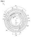
- FIG. 1 is a cross-sectional view of a floating bush bearing device according to an embodiment of the present invention.
- a floating bush bearing device 1a according to the present embodiment includes a bearing housing 10 and a floating bush 20 as shown in FIG. 1 , and rotatably supports a rotation shaft R.
- the bearing housing 10 has a cylindrical cross-sectional shape as shown in FIG. 1 , and has a first recess portion 14a formed at an upper side position in the figure, and a second recess portion 14b formed at a position in an inner circumferential surface 10a on the opposite side of the first recess portion 14a in a circumference direction.
- the first recess portion 14a and the second recess portion 14b are different from each other in area.
- the first recess portion 14a has a larger area.
- An arrow F in the figure indicates a load direction of the rotation shaft R.
- the second recess portion 14b is formed at a portion of the inner circumferential surface 10a of the bearing housing on a side of a load direction F.
- a width Ba of the first recess portion 14a is larger than a width Bb of the second recess portion 14b.
- a length La of the first recess portion 14a is the same as a length Lb of the second recess portion 14b.
- an area Aa of the first recess portion 14a is larger than an area Ab of the second recess portion 14b.
- Ba and Bb may be the same when La > Lb holds true so that the first recess portion 14a has a larger area.
- the first recess portion 14a and the second recess portion 14b are connected to each other through an oil groove 16 which extends in a circumference direction and is formed in the inner circumferential surface 10a of the bearing housing.
- a housing side oil supply hole 12 extending in a radial direction is formed through the bearing housing 10. Pressurized lubricating oil is supplied between an outer circumferential surface 20b of the floating bush 20 and the inner circumferential surface 10a of the bearing housing 10 through the housing side oil supply hole 12, whereby an oil film is formed between the outer circumferential surface 20b and the inner circumferential surface 10a.
- the housing side oil supply hole 12 is in communication with the first recess portion 14a with a larger area, and the lubricating oil is supplied to the second recess portion 14b through the oil groove 16 described above and the clearance between the inner circumferential surface 10a and the outer circumferential surface 20a of the floating bush.
- an oil pressure at the first recess portion 14a is higher than an oil pressure at the second recess portion 14b.
- the first recess portion 14a has a larger area than the second recess portion 14b.
- an oil supply pressure for pushing down the floating bush 20 by the first recess portion 14a (the oil pressure at the first recess portion 14a ⁇ the area of the first recess portion 14a) is larger than an oil supply pressure for pushing up the floating bush 20 by the second recess portion 14b (the oil pressure at the second recess portion 14b ⁇ the area of the second recess portion 14b).
- the floating bush 20 is disposed between the rotation shaft R and the inner circumferential surface 10a of the bearing housing 10 in the bearing housing 10.
- the floating bush 20 is disposed in the bearing housing 10 to be rotatable in a direction indicated by an arrow r in FIG. 1 , together with the rotation shaft R.
- the floating bush 20 has a multi-arc shape formed by combining three arc portions 20A having the inner circumferential surfaces 20a with different center points.
- a gap portion g between the rotation shaft having a predetermined clearance or larger is formed between the rotation shaft R and an inner circumferential surface 20a of the floating bush 20 regardless of the relative positions between the rotation shaft R and the inner circumferential surface 20a of the floating bush 20, that is, even when the rotation shaft R, having a circular cross-sectional shape, moves in the floating bush 20, as illustrated in a two-dotted dashed line in the figure.
- a bush side oil supply hole 22 extending in the radial direction, is formed through the floating bush 20, and is in communication with the gap portion g described above.
- the lubricating oil supplied into the clearance between the outer circumferential surface 20b of the floating bush and the inner circumferential surface 10a of the bearing housing, is further supplied into the clearance between the rotation shaft R and the inner circumferential surface 20a of the floating bush through a bush side oil supply hole 2.
- the bush side oil supply hole 22 is in communication with the gap portion g as described above, whereby the lubricating oil is stably supplied to the inner side of the floating bush 20 regardless of the position of the rotation shaft R.
- the three arc portions 20A have the outer circumferential surfaces 20b with different center points.
- a gap portion g' having a predetermined clearance or larger regardless of the position of the floating bush 20, is formed between the inner circumferential surface 10a of the bearing housing 10 and the outer circumferential surface 20b of the floating bush 20.
- the bush side oil supply hole 22 described above is in communication with the gap portion g'.
- the inner circumferential surfaces 20a of the floating bush 20 define a non-circular shape with the multi-arc shape.
- the clearance between the inner circumferential surface 20a of the floating bush 20 and the rotation shaft R is non-uniform in the circumference direction, and the gap portion g, having the predetermined clearance or larger regardless of the relative positions between the inner circumferential surface 20a of the floating bush 20 and the rotation shaft R, is formed.
- a cross section is reduced with respect to a bearing dynamic characteristic direct section, whereby the oscillation stability of the bearing device can be improved.
- a larger average clearance between the rotation shaft R and the inner circumferential surface 20a of the floating bush 20 can be achieved, whereby a bearing loss can be reduced compared with a case where the inner circumferential surface 20a of the floating bush has a perfect circle shape.
- the bush side oil supply hole 22 is in communication with the gap portion g.
- the oil supply characteristics on the inner side of the floating bush 20 can be improved, whereby the oscillation stability can be improved and furthermore, the bearing loss can be reduced.
- the housing side oil supply hole 12 is in communication with the first recess portion 14a having a larger area.
- the floating bush 20 is pushed toward the second recess portion 14b, due to the difference between the two recess portions of the first recess portion 14a and the second recess portion 14b in the oil supply pressure.
- a higher eccentricity ratio of the floating bush 20 is achieved, whereby higher oscillation stability can be achieved.
- the recess portions are respectively formed on a load direction side of the rotation shaft R and the side opposite to the load direction side.
- the first recess portion 14a and the second recess portion 14b each function as an oil reservoir, whereby higher oil supply characteristics on the inner side of the floating bush 20 can be achieved.
- the first recess portion 14a and the second recess portion 14b are connected to each other through the oil groove 16.
- the lubricating oil can be further supplied into the second recess portion 14b, which is not in communication with the housing side oil supply hole 12, through the oil groove 16, whereby higher oil supply characteristics on the inner side of the floating bush 20 can be achieved.
- the housing side oil supply hole 12 is in communication with the first recess portion 14a, which is formed on the opposite side of the side of the load direction F of the rotation shaft R.
- the rotation shaft R is further pushed in the load direction F thereof due to the above-described difference between the first recess portion 14a and the second recess portion 14b in the oil supply pressure.
- even higher eccentricity ratio of the floating bush 20 can be achieved, whereby the oscillation stability of the bearing can be improved.
- the housing side oil supply hole 12 may be in communication with the second recess portion 14b formed on the side of the load direction F of the rotation shaft R as in a floating bush bearing device 1b shown in FIG. 3 .
- floating of the floating bush 20 is achieved by the pressurized lubricating oil supplied from the housing side oil supply hole 12.
- the oil film is swiftly formed in the clearance between the inner circumferential surface 10a of the bearing housing 10 and the outer circumferential surface 20b of the floating bush 20, whereby the bearing loss at the time of the rotation start can be reduced and the startability can be improved.
- the clearance between the inner circumferential surface 10a of the bearing housing 10 and the outer circumferential surface 20b of the floating bush 20 is non-uniform in the circumference direction, and the gap portion g' is formed in the clearance between the inner circumferential surface 10a of the bearing housing 10 and the outer circumferential surface 20b of the floating bush 20.
- the floating bush bearing device 1 according to the present invention is not limited to this.
- the clearance between the inner circumferential surface 10a of the bearing housing 10 and the outer circumferential surface 20b of the floating bush 20 may be uniform in the circumference direction as in a floating bush bearing device 1c illustrated in FIG.
- the floating bush 20 has the multi-arc shape formed by combining the three arc portions 20A having the inner circumferential surfaces 20a with different center points.
- the floating bush bearing device 1 according to the present invention is not limited to this. Any number of arc portions may be combined as appropriate. The number of the arc portions to be combined is preferably two to five for the sake of productivity.
- FIG. 5 shows an example of a floating bush bearing device 1d including the floating bush 20 formed by combining two arc portions 20B having the inner circumferential surfaces 20a with different center points.
- the inner circumferential surface 20a of the floating bush 20 may have an elliptical shape, as in a floating bush bearing device 1e shown in FIG. 6 .
- the inner circumferential surface 20a of the floating bush 20 described above can geometrically easily be formed to have a non-circular shape. Furthermore, for example, the clearance between the rotation shaft R and the inner circumferential surface 20a of the floating bush 20 can be more gently changed, compared with a case where the inner circumferential surface 20a of the floating bush 20 has recesses and protrusions.
- FIG. 7 is a vertical cross-sectional view of a floating bush of a floating bush according to an embodiment of the present invention.
- the floating bush 20 according to the present embodiment has basically the same configuration as the floating bush 20 in the embodiment described above.
- the same components are denoted with the same reference numerals and the detail description thereof will be omitted.
- a circumference direction groove 24 is formed along the circumference direction in the outer circumferential surface 20b as shown in FIG. 7 .
- the circumference direction groove 24 is formed over the entire circumference of the outer circumferential surface 20b.
- the number of the circumference direction grooves 24 is not particularly limited. In the example shown in FIG. 7 , a single circumference direction groove 24 is continuously formed over the entire circumference of the outer circumferential surface 20b of the floating bush 20 for example.
- Such a circumference direction groove 24 can reduce a friction torque on the outer circumferential surface 20b of the floating bush 20 so that the rotation speed of the floating bush 20 increases, whereby the bearing loss on the inner side of the floating bush 20 can be reduced.
- the circumference direction groove 24 provides a squeezing effect to achieve higher reduction effect of the lubricating oil. All things considered, the oscillation stability is improved.
- the bush side oil supply hole 22 described above may be in communication with the circumference direction groove 24.
- the oil supply characteristics on the inner side of the floating bush 20 can be improved, the oscillation stability can be improved and the bearing loss can be reduced.
- FIG. 8 is an outer view of a floating bush according to an embodiment of the present invention.
- the floating bush 20 according to the present embodiment has basically the same configuration as the floating bush 20 in the embodiments described above.
- the same components are denoted with the same reference numerals and the detail description thereof will be omitted.
- a plurality of partial grooves 26a are formed in the outer circumferential surface 20b.
- the partial groove 26a has a V shape in a plan view formed by two groove portions 27a and 28a, extending in different directions inclined with respect to an axial direction, intersecting with each other.
- the partial groove 26a has an opening side of a V shape on the rotation direction side in the rotation direction r of the floating bush 20.
- the bush side oil supply hole 22 described above is in communication with the intersecting portion between the two groove portions 27a and 28a.
- the lubricating oil can be easily collected in the intersecting portion through the groove portions 27a and 28a, when the floating bush 20 rotates.
- the bush side oil supply hole 22 is in communication with the intersecting portion in which the lubricating oil is easily collected. Thus, even higher oil supply characteristics on the inner side of the floating bush 20 can be achieved.
- the embodiment of the partial groove 26 is not limited to the embodiment of the partial groove 26a shown in FIG. 8 .
- an embodiment where elongated partial grooves 26b have a longitudinal direction extending along the circumference direction, and may form a staggered pattern may be employed.
- the bush side oil supply hole 22 is in communication with the elongated partial groove 26b at a position on an opposite side of the rotation direction r of the floating bush 20.
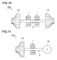
- FIG. 10 is a schematic view of an embodiment of a supercharger including the floating bush bearing device according to the present invention.
- a supercharger 100 according to the present embodiment is formed as a turbocharger 100a including the rotation shaft R, a compressor rotor 102 and a turbine rotor 104 that are respectively coupled to both end portions of the rotation shaft R, and the floating bush bearing device 1 described above rotatably supports the rotation shaft R.
- the compressor rotor 102 is disposed in an intake path of an engine, and the turbine rotor 104 is disposed in an exhaust path of the engine.
- the turbine rotor 104 is rotated by exhaust gas from the engine, and the compressor rotor 102 is coaxially operated in response to the rotation.
- air flowing in the intake path is compressed, whereby turbocharged air is supplied to the engine.
- the turbocharger 100a including the floating bush bearing device with excellent oscillation stability and small bearing loss can be provided.
- the supercharger 100 according to the present invention is not limited to the turbocharger 100a described above.
- an electric supercharger 100b may be formed that includes an electric motor 106 instead of the turbine rotor 104.
- the compressor rotor 102 is driven when the rotation shaft R is rotated by the electric motor 106.
- At least one embodiment of the present invention is suitably used, as a floating bush bearing device that rotatably supports a rotation shaft, in a small supercharger mounted in an automobile engine for example.
Landscapes
- Engineering & Computer Science (AREA)
- General Engineering & Computer Science (AREA)
- Mechanical Engineering (AREA)
- Chemical & Material Sciences (AREA)
- Oil, Petroleum & Natural Gas (AREA)
- Physics & Mathematics (AREA)
- Fluid Mechanics (AREA)
- Sliding-Contact Bearings (AREA)
- Supercharger (AREA)
- Support Of The Bearing (AREA)
Abstract
Description
- The present invention relates to a floating bush bearing device which rotatably supports a rotation shaft and a supercharger including the floating bush bearing device.
- A floating bush bearing device has been known which is formed by rotatably disposing a floating bush between a bearing housing and a rotation shaft in a bearing device rotatably supporting the rotation shaft (for example, see Patent Document 1). In the floating bush bearing device, an oil film is formed by supplying lubricating oil into a clearance between the bearing housing and the floating bush, and into a clearance between the floating bush and the rotation shaft. The rotation shaft is rotatably supported by the oil film formed in the clearances.
- Patent Document 1: Japanese Patent Application Laid-Open No.
2012-207584 - In a conventional floating bush bearing device, inner and outer circumferential surfaces of the rotation shaft and the floating bush as well as an inner circumferential surface of the bearing housing each have a circular lateral cross-sectional shape. The present inventors have found out that asynchronous oscillation, not in synchronization with the rotation of the rotation shaft, is likely to occur in such a conventional floating bush bearing device. The asynchronous oscillation is particularly likely to occur in a small supercharger mounted in an automobile engine for example.
- At least one embodiment of the present invention is made in view of the problem in the conventional device described above, and an object of the present invention is to provide a floating bush bearing device with excellent oscillation stability and small bearing loss, and a supercharger including the floating bush bearing device.
- To achieve the object described above, at least one embodiment of the present invention provides a floating bush bearing device which rotatably supports a rotation shaft, the floating bush bearing device including: a bearing housing, a floating bush rotatably disposed between the rotation shaft and an inner circumferential surface of the bearing housing, in the bearing housing, and a bush side oil supply hole which is formed through the floating bush and is capable of supplying lubricating oil between the rotation shaft and the inner circumferential surface of the floating bush. The inner circumferential surface of the floating bush has a non-circular shape so that a gap portion is formed between the rotation shaft and the inner circumferential surface of the floating bush, the gap portion having a predetermined clearance or larger regardless of relative positions of the rotation shaft and the inner circumferential surface of the floating bush. The bush side oil supply hole communicates with the gap portion.
- In such a floating bush bearing device, the inner circumferential surface of the floating bush has the non-circular shape, so that the clearance between the inner circumferential surface of the floating bush and the rotation shaft is non-uniform in the circumference direction, and the gap portion having a predetermined clearance or larger regardless of relative positions of the rotation shaft and the inner circumferential surface of the floating bush is formed. Thus, a cross section is reduced with respect to a bearing dynamic characteristic direct section, whereby the oscillation stability of the bearing device can be improved. Furthermore, a larger average clearance between the rotation shaft and the inner circumferential surface of the floating bush can be achieved, whereby a bearing loss can be reduced compared with a case where the inner circumferential surface of the floating bush has a perfect circle shape.
- The bush side oil supply hole is in communication with the gap portion, whereby higher oil supply characteristics on the inner side of the floating bush can be achieved, the oscillation stability can be improved, and the bearing loss can be reduced.
- In one embodiment of the present invention, the inner circumferential surface of the floating bush has a multi-arc shape, formed by combining a plurality of arcs with different center points, or has an elliptical shape.
- In such a configuration, the inner circumferential surface of the floating bush described above can geometrically easily be formed to have a non-circular shape. Furthermore, for example, the clearance between the rotation shaft and the inner circumferential surface of the floating bush can be more gently changed, compared with a case where the inner circumferential surface of the floating bush has recesses and protrusions.
- In one embodiment of the present invention, recess portions, having different areas, are respectively formed on a load direction side of the rotation shaft and a side opposite to the load direction side, in the inner circumferential surface of the bearing housing, and one of the recess portions with a larger area communicates with a housing side oil supply hole which is formed through the bearing housing and is capable of supplying lubricating oil between an outer circumferential surface of the floating bush and the inner circumferential surface of the bearing housing.
- In such a configuration, the housing side oil supply hole is in communication with the recess portion having a larger area, whereby the floating bush is pushed toward the floating bush having a smaller area due to the difference between the two recess portions in the oil supply pressure (oil supply pressure = oil pressure x area). As a result, even higher eccentricity ratio of the floating bush can be achieved, whereby the oscillation stability of the bearing can be improved.
- The recess portions are respectively formed on the load direction side of the rotation shaft and the side opposite to the load direction side. Thus, the first recess portion and the second recess portion each function as an oil reservoir, whereby higher oil supply characteristics on the inner side of the floating bush can be achieved.
- In one embodiment of the present invention, an oil groove is formed in the inner circumferential surface of the bearing housing, the oil groove connecting between the two recess portions respectively formed on the load direction side of the rotation shaft and the side opposite to the load direction side.
- In such a configuration, the lubricating oil can be further supplied into the second recess portion, which is not in communication with the housing side oil supply hole, through the oil groove, whereby higher oil supply characteristics on the inner side of the floating bush can be achieved.
- In one embodiment of the present invention, the housing side oil supply hole communicates with a first recess portion formed on the side opposite to the load direction side of the rotation shaft in the inner circumferential surface of the bearing housing.
- In such a configuration, the housing side oil supply hole is in communication with the first recess portion formed on the side opposite to the load direction side of the rotation shaft. Thus, the rotation shaft is further pushed in the load direction thereof due to the above-described difference between the first recess portion and the second recess portion in the oil supply pressure. As a result, even higher eccentricity ratio of the floating bush can be achieved, whereby the oscillation stability of the bearing can be improved.
- In one embodiment of the present invention, the housing side oil supply hole communicates with a second recess portion on the load direction side of the rotation shaft in the inner circumferential surface of the bearing housing.
- In such a configuration, the housing side oil supply hole is in communication with the second recess portion formed on the load direction side of the rotation shaft, whereby floating of the floating bush can be easily achieved, and the startability can be improved.
- In one embodiment of the present invention, a circumference direction groove, extending along a circumference direction, is formed in the outer circumferential surface of the floating bush.
- In such a configuration, a friction torque on the outer circumferential surface of the floating bush is reduced, so that the rotation speed of the floating bush increases, whereby the bearing loss on the inner side of the floating bush can be reduced. The circumference direction groove provides a squeezing effect to achieve higher reduction effect of the lubricating oil. All things considered, the oscillation stability is improved.
- In one embodiment of the present invention, a plurality of partial grooves are formed in the outer circumferential surface of the floating bush, and the bush side oil supply hole communicates with the partial holes.
- In such a configuration, the higher oil supply characteristics on the inner side of the floating bush can be achieved, the oscillation stability can be improved, and the bearing loss can be reduced.
- In one embodiment of the present invention, the partial grooves have a V shape in a plan view formed by two groove portions intersecting with each other, each of two groove portions extending in different directions inclined with respect to an axial direction, and which have an opening side on a rotation direction side of the floating bush, and the bush side oil supply hole communicates with an intersecting portion between the two groove portions.
- In such a configuration, the bush side oil supply hole is in communication with the intersecting portion between the two groove portions where the lubricating oil is easily collected. Thus, even higher oil supply characteristics on the inner side of the floating bush can be achieved.
- A supercharger according to at least one embodiment of the present invention includes: a rotation shaft; a compressor rotor coupled to one end portion of the rotation shaft; and the floating bush bearing device which rotatably supports the rotation shaft according to any one of the embodiments.
- Thus, the supercharger including the floating bush bearing device with excellent oscillation stability and small bearing loss can be formed.
- With at least one embodiment of the present invention, a floating bush bearing device with excellent oscillation stability and small bearing loss, and a supercharger including the floating bush bearing device can be provided.
-
-
FIG. 1 is a cross-sectional view of a floating bush bearing device according to an embodiment of the present invention. -
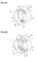
FIGs. 2A and 2B are diagrams for schematically illustrating a recess portion formed in an inner circumferential surface of a bearing housing. -
FIG. 3 is a cross-sectional view of a modification of the floating bush bearing device according to the embodiment of the present invention. -
FIG. 4 is a cross-sectional view of a modification of the floating bush bearing device according to the embodiment of the present invention. -
FIG. 5 is a cross-sectional view of a modification of the floating bush bearing device according to the embodiment of the present invention. -
FIG. 6 is a cross-sectional view of a modification of the floating bush bearing device according to the embodiment of the present invention. -
FIG. 7 is a vertical cross-sectional view of a floating bush of a floating bush according to an embodiment of the present invention. -
FIG. 8 is an outer view of a floating bush according to an embodiment of the present invention. -
FIG. 9 is a diagram illustrating a modification of the floating bush illustrated inFIG.8 -
FIG. 10 is a schematic view of an embodiment of a supercharger including the floating bush bearing device according to the present invention. -
FIG. 11 is a schematic view of an embodiment of a supercharger including the floating bush bearing device according to the present invention. - Embodiments of the present invention are described in detail with reference to the drawings. It is intended, however, that the scope of the present invention is not limited to the embodiments described above. Dimensions, materials, shapes, relative positions, and the like of components described in the embodiments shall be interpreted as illustrative only and not limitative of the scope of the present invention unless otherwise specified.
-
FIG. 1 is a cross-sectional view of a floating bush bearing device according to an embodiment of the present invention. A floatingbush bearing device 1a according to the present embodiment includes a bearinghousing 10 and a floatingbush 20 as shown inFIG. 1 , and rotatably supports a rotation shaft R. - The bearing
housing 10 has a cylindrical cross-sectional shape as shown inFIG. 1 , and has afirst recess portion 14a formed at an upper side position in the figure, and asecond recess portion 14b formed at a position in an innercircumferential surface 10a on the opposite side of thefirst recess portion 14a in a circumference direction. Thefirst recess portion 14a and thesecond recess portion 14b are different from each other in area. In the bearinghousing 10 of the present embodiment, thefirst recess portion 14a has a larger area. An arrow F in the figure indicates a load direction of the rotation shaft R. Thesecond recess portion 14b is formed at a portion of the innercircumferential surface 10a of the bearing housing on a side of a load direction F. - As shown in
FIG. 2A , in the bearinghousing 10 shown inFIG. 1 , a width Ba of thefirst recess portion 14a is larger than a width Bb of thesecond recess portion 14b. A length La of thefirst recess portion 14a is the same as a length Lb of thesecond recess portion 14b. Thus, an area Aa of thefirst recess portion 14a is larger than an area Ab of thesecond recess portion 14b. - Alternatively, as shown in
FIG. 2B , Ba and Bb may be the same when La > Lb holds true so that thefirst recess portion 14a has a larger area. - As shown in
FIGs. 2A and 2B , thefirst recess portion 14a and thesecond recess portion 14b are connected to each other through anoil groove 16 which extends in a circumference direction and is formed in the innercircumferential surface 10a of the bearing housing. - As shown in
FIG. 1 , a housing sideoil supply hole 12 extending in a radial direction is formed through the bearinghousing 10. Pressurized lubricating oil is supplied between an outercircumferential surface 20b of the floatingbush 20 and the innercircumferential surface 10a of the bearinghousing 10 through the housing sideoil supply hole 12, whereby an oil film is formed between the outercircumferential surface 20b and the innercircumferential surface 10a. - The housing side
oil supply hole 12 is in communication with thefirst recess portion 14a with a larger area, and the lubricating oil is supplied to thesecond recess portion 14b through theoil groove 16 described above and the clearance between the innercircumferential surface 10a and the outercircumferential surface 20a of the floating bush. Thus, an oil pressure at thefirst recess portion 14a is higher than an oil pressure at thesecond recess portion 14b. As described above, thefirst recess portion 14a has a larger area than thesecond recess portion 14b. Thus, an oil supply pressure for pushing down the floatingbush 20 by thefirst recess portion 14a (the oil pressure at thefirst recess portion 14a × the area of thefirst recess portion 14a) is larger than an oil supply pressure for pushing up the floatingbush 20 by thesecond recess portion 14b (the oil pressure at thesecond recess portion 14b × the area of thesecond recess portion 14b). - As shown in
FIG. 1 , the floatingbush 20 is disposed between the rotation shaft R and the innercircumferential surface 10a of the bearinghousing 10 in the bearinghousing 10. The floatingbush 20 is disposed in the bearinghousing 10 to be rotatable in a direction indicated by an arrow r inFIG. 1 , together with the rotation shaft R. - As shown in
FIG. 1 , the floatingbush 20 has a multi-arc shape formed by combining threearc portions 20A having the innercircumferential surfaces 20a with different center points. A gap portion g between the rotation shaft having a predetermined clearance or larger is formed between the rotation shaft R and an innercircumferential surface 20a of the floatingbush 20 regardless of the relative positions between the rotation shaft R and the innercircumferential surface 20a of the floatingbush 20, that is, even when the rotation shaft R, having a circular cross-sectional shape, moves in the floatingbush 20, as illustrated in a two-dotted dashed line in the figure. - As shown in
FIG. 1 , a bush sideoil supply hole 22, extending in the radial direction, is formed through the floatingbush 20, and is in communication with the gap portion g described above. The lubricating oil, supplied into the clearance between the outercircumferential surface 20b of the floating bush and the innercircumferential surface 10a of the bearing housing, is further supplied into the clearance between the rotation shaft R and the innercircumferential surface 20a of the floating bush through a bush side oil supply hole 2. Thus, the oil film is formed in the clearances. The bush sideoil supply hole 22 is in communication with the gap portion g as described above, whereby the lubricating oil is stably supplied to the inner side of the floatingbush 20 regardless of the position of the rotation shaft R. - As shown in
FIG. 1 , the threearc portions 20A have the outercircumferential surfaces 20b with different center points. A gap portion g', having a predetermined clearance or larger regardless of the position of the floatingbush 20, is formed between the innercircumferential surface 10a of the bearinghousing 10 and the outercircumferential surface 20b of the floatingbush 20. The bush sideoil supply hole 22 described above is in communication with the gap portion g'. Thus, the lubricating oil is stably supplied to the inner side of the floatingbush 20 regardless of the position of the floatingbush 20. - As described above, in the floating
bush bearing device 1a according to the present embodiment having the configuration described above, the innercircumferential surfaces 20a of the floatingbush 20 define a non-circular shape with the multi-arc shape. Thus, the clearance between the innercircumferential surface 20a of the floatingbush 20 and the rotation shaft R is non-uniform in the circumference direction, and the gap portion g, having the predetermined clearance or larger regardless of the relative positions between the innercircumferential surface 20a of the floatingbush 20 and the rotation shaft R, is formed. Thus, a cross section is reduced with respect to a bearing dynamic characteristic direct section, whereby the oscillation stability of the bearing device can be improved. Furthermore, a larger average clearance between the rotation shaft R and the innercircumferential surface 20a of the floatingbush 20 can be achieved, whereby a bearing loss can be reduced compared with a case where the innercircumferential surface 20a of the floating bush has a perfect circle shape. - As described above, the bush side
oil supply hole 22 is in communication with the gap portion g. Thus, the oil supply characteristics on the inner side of the floatingbush 20 can be improved, whereby the oscillation stability can be improved and furthermore, the bearing loss can be reduced. - As described above, the housing side
oil supply hole 12 is in communication with thefirst recess portion 14a having a larger area. Thus, the floatingbush 20 is pushed toward thesecond recess portion 14b, due to the difference between the two recess portions of thefirst recess portion 14a and thesecond recess portion 14b in the oil supply pressure. As a result, a higher eccentricity ratio of the floatingbush 20 is achieved, whereby higher oscillation stability can be achieved. - As described above, the recess portions are respectively formed on a load direction side of the rotation shaft R and the side opposite to the load direction side. Thus, the
first recess portion 14a and thesecond recess portion 14b each function as an oil reservoir, whereby higher oil supply characteristics on the inner side of the floatingbush 20 can be achieved. - As described above, the
first recess portion 14a and thesecond recess portion 14b are connected to each other through theoil groove 16. Thus, the lubricating oil can be further supplied into thesecond recess portion 14b, which is not in communication with the housing sideoil supply hole 12, through theoil groove 16, whereby higher oil supply characteristics on the inner side of the floatingbush 20 can be achieved. - In the embodiment described above, the housing side
oil supply hole 12 is in communication with thefirst recess portion 14a, which is formed on the opposite side of the side of the load direction F of the rotation shaft R. Thus, the rotation shaft R is further pushed in the load direction F thereof due to the above-described difference between thefirst recess portion 14a and thesecond recess portion 14b in the oil supply pressure. As a result, even higher eccentricity ratio of the floatingbush 20 can be achieved, whereby the oscillation stability of the bearing can be improved. - On the other hand, the housing side
oil supply hole 12 may be in communication with thesecond recess portion 14b formed on the side of the load direction F of the rotation shaft R as in a floatingbush bearing device 1b shown inFIG. 3 . In this configuration in which the housing sideoil supply hole 12 is in communication with thesecond recess portion 14b on the side of the load direction F of the rotation shaft R, floating of the floatingbush 20 is achieved by the pressurized lubricating oil supplied from the housing sideoil supply hole 12. Thus, the oil film is swiftly formed in the clearance between the innercircumferential surface 10a of the bearinghousing 10 and the outercircumferential surface 20b of the floatingbush 20, whereby the bearing loss at the time of the rotation start can be reduced and the startability can be improved. - In the embodiment described above, the clearance between the inner
circumferential surface 10a of the bearinghousing 10 and the outercircumferential surface 20b of the floatingbush 20 is non-uniform in the circumference direction, and the gap portion g' is formed in the clearance between the innercircumferential surface 10a of the bearinghousing 10 and the outercircumferential surface 20b of the floatingbush 20. However, the floatingbush bearing device 1 according to the present invention is not limited to this. The clearance between the innercircumferential surface 10a of the bearinghousing 10 and the outercircumferential surface 20b of the floatingbush 20 may be uniform in the circumference direction as in a floatingbush bearing device 1c illustrated inFIG. 4 , as long as the clearance between the rotation shaft R and the innercircumferential surface 20a of the floatingbush 20 is non-uniform, and the gap portion g is formed in the clearance between rotation shaft R and the innercircumferential surface 20a of the floatingbush 20. - In the embodiment described above, the floating
bush 20 has the multi-arc shape formed by combining the threearc portions 20A having the innercircumferential surfaces 20a with different center points. However, the floatingbush bearing device 1 according to the present invention is not limited to this. Any number of arc portions may be combined as appropriate. The number of the arc portions to be combined is preferably two to five for the sake of productivity.FIG. 5 shows an example of a floatingbush bearing device 1d including the floatingbush 20 formed by combining twoarc portions 20B having the innercircumferential surfaces 20a with different center points. The innercircumferential surface 20a of the floatingbush 20 may have an elliptical shape, as in a floatingbush bearing device 1e shown inFIG. 6 . - In such a configuration, the inner
circumferential surface 20a of the floatingbush 20 described above can geometrically easily be formed to have a non-circular shape. Furthermore, for example, the clearance between the rotation shaft R and the innercircumferential surface 20a of the floatingbush 20 can be more gently changed, compared with a case where the innercircumferential surface 20a of the floatingbush 20 has recesses and protrusions. -
FIG. 7 is a vertical cross-sectional view of a floating bush of a floating bush according to an embodiment of the present invention. The floatingbush 20 according to the present embodiment has basically the same configuration as the floatingbush 20 in the embodiment described above. The same components are denoted with the same reference numerals and the detail description thereof will be omitted. - In the floating
bush 20 according to the present embodiment, acircumference direction groove 24 is formed along the circumference direction in the outercircumferential surface 20b as shown inFIG. 7 . Preferably, thecircumference direction groove 24 is formed over the entire circumference of the outercircumferential surface 20b. However, there may be a portion where thecircumference direction groove 24 is not formed in the circumference direction. The number of thecircumference direction grooves 24 is not particularly limited. In the example shown inFIG. 7 , a singlecircumference direction groove 24 is continuously formed over the entire circumference of the outercircumferential surface 20b of the floatingbush 20 for example. - Such a
circumference direction groove 24 can reduce a friction torque on the outercircumferential surface 20b of the floatingbush 20 so that the rotation speed of the floatingbush 20 increases, whereby the bearing loss on the inner side of the floatingbush 20 can be reduced. Thecircumference direction groove 24 provides a squeezing effect to achieve higher reduction effect of the lubricating oil. All things considered, the oscillation stability is improved. - As shown in
FIG. 7 , the bush sideoil supply hole 22 described above may be in communication with thecircumference direction groove 24. Thus, the oil supply characteristics on the inner side of the floatingbush 20 can be improved, the oscillation stability can be improved and the bearing loss can be reduced. -
FIG. 8 is an outer view of a floating bush according to an embodiment of the present invention. The floatingbush 20 according to the present embodiment has basically the same configuration as the floatingbush 20 in the embodiments described above. The same components are denoted with the same reference numerals and the detail description thereof will be omitted. - As shown in
FIG. 8 , in the floatingbush 20 according to the present embodiment, a plurality ofpartial grooves 26a are formed in the outercircumferential surface 20b. Thepartial groove 26a has a V shape in a plan view formed by twogroove portions partial groove 26a has an opening side of a V shape on the rotation direction side in the rotation direction r of the floatingbush 20. The bush sideoil supply hole 22 described above is in communication with the intersecting portion between the twogroove portions - In such a configuration, the lubricating oil can be easily collected in the intersecting portion through the
groove portions bush 20 rotates. The bush sideoil supply hole 22 is in communication with the intersecting portion in which the lubricating oil is easily collected. Thus, even higher oil supply characteristics on the inner side of the floatingbush 20 can be achieved. - The embodiment of the partial groove 26 is not limited to the embodiment of the
partial groove 26a shown inFIG. 8 . For example, as shown inFIG. 9 , an embodiment where elongatedpartial grooves 26b have a longitudinal direction extending along the circumference direction, and may form a staggered pattern may be employed. Here, as shown inFIG. 9 , the bush sideoil supply hole 22 is in communication with the elongatedpartial groove 26b at a position on an opposite side of the rotation direction r of the floatingbush 20. Thus, the lubricating oil can be easily collected in the bush sideoil supply hole 22 when the floatingbush 20 rotates, whereby even higher oil supply characteristics on the inner side of the floatingbush 20 can be achieved. -
FIG. 10 is a schematic view of an embodiment of a supercharger including the floating bush bearing device according to the present invention. As shown inFIG. 10 , a supercharger 100 according to the present embodiment is formed as aturbocharger 100a including the rotation shaft R, acompressor rotor 102 and aturbine rotor 104 that are respectively coupled to both end portions of the rotation shaft R, and the floatingbush bearing device 1 described above rotatably supports the rotation shaft R. - The
compressor rotor 102 is disposed in an intake path of an engine, and theturbine rotor 104 is disposed in an exhaust path of the engine. Theturbine rotor 104 is rotated by exhaust gas from the engine, and thecompressor rotor 102 is coaxially operated in response to the rotation. Thus, air flowing in the intake path is compressed, whereby turbocharged air is supplied to the engine. - In such a configuration, the
turbocharger 100a including the floating bush bearing device with excellent oscillation stability and small bearing loss can be provided. - The supercharger 100 according to the present invention is not limited to the
turbocharger 100a described above. As shown inFIG. 11 , anelectric supercharger 100b may be formed that includes anelectric motor 106 instead of theturbine rotor 104. Here, thecompressor rotor 102 is driven when the rotation shaft R is rotated by theelectric motor 106. - The preferred embodiment of the present invention are described above. However, the present invention is not limited to the embodiments described above, and various modifications may be made without departing from the object of the present invention.
- At least one embodiment of the present invention is suitably used, as a floating bush bearing device that rotatably supports a rotation shaft, in a small supercharger mounted in an automobile engine for example.
-
- 1, 1a to 1e
- floating bush bearing device
- 10
- bearing housing
- 10a
- inner circumferential surface of bearing housing
- 12
- housing side oil supply hole
- 14a, 14b
- recess portion
- 16
- oil groove
- 20
- floating bush
- 20a
- circumferential surface of floating bush inner
- 20b
- outer circumferential surface of floating bush
- 20A, 20B
- arc portion
- 22
- bush side oil supply hole
- 24
- circumference direction groove
- 26a, 26b
- partial groove
- 27a, 28a
- groove portion
- 100
- supercharger
- 100a
- turbocharger
- 100b
- electric supercharger
- 102
- compressor rotor
- 104
- turbine rotor
- 106
- electric motor
Claims (10)
- A floating bush bearing device which rotatably supports a rotation shaft, the floating bush bearing device comprising:a bearing housing;a floating bush rotatably disposed between the rotation shaft and an inner circumferential surface of the bearing housing, in the bearing housing; anda bush side oil supply hole which is formed through the floating bush and is capable of supplying lubricating oil between the rotation shaft and the inner circumferential surface of the floating bush, whereinthe inner circumferential surface of the floating bush has a non-circular shape so that a gap portion is formed between the rotation shaft and the inner circumferential surface of the floating bush, the gap portion having a predetermined clearance or larger regardless of relative positions of the rotation shaft and the inner circumferential surface of the floating bush, andthe bush side oil supply hole communicates with the gap portion.
- The floating bush bearing device according to claim 1, wherein the inner circumferential surface of the floating bush has a multi-arc shape, formed by combining a plurality of arcs with different center points, or has an elliptical shape.
- The floating bush bearing device according to claim 1 or 2, wherein
recess portions, having different areas, are respectively formed on a load direction side of the rotation shaft and a side opposite to the load direction side, in the inner circumferential surface of the bearing housing, and
one of the recess portions with a larger area communicates with a housing side oil supply hole which is formed through the bearing housing and is capable of supplying lubricating oil between an outer circumferential surface of the floating bush and the inner circumferential surface of the bearing housing. - The floating bush bearing device according to claim 3, wherein an oil groove is formed in the inner circumferential surface of the bearing housing, the oil groove connecting between the two recess portions respectively formed on the load direction side of the rotation shaft and the side opposite to the load direction side.
- The floating bush bearing device according to claim 3 or 4, wherein the housing side oil supply hole communicates with a first recess portion formed on the side opposite to the load direction side of the rotation shaft in the inner circumferential surface of the bearing housing.
- The floating bush bearing device according to claim 3 or 4, wherein the housing side oil supply hole communicates with a second recess portion on the load direction side of the rotation shaft in the inner circumferential surface of the bearing housing.
- The floating bush bearing device according to any one of claims 1 to 6, wherein a circumference direction groove, extending along a circumference direction, is formed in the outer circumferential surface of the floating bush.
- The floating bush bearing device according to any one of claims 1 to 6, wherein a plurality of partial grooves are formed in the outer circumferential surface of the floating bush, and the bush side oil supply hole communicates with the partial holes.
- The floating bush bearing device according to claim 8, wherein
the partial grooves have a V shape in a plan view formed by two groove portions intersecting with each other, each of two groove portions extending in different directions inclined with respect to an axial direction, and which have an opening side on a rotation direction side of the floating bush, and
the bush side oil supply hole communicates with an intersecting portion between the two groove portions. - A supercharger comprising:a rotation shaft;a compressor rotor coupled to one end portion of the rotation shaft; andthe floating bush bearing device which rotatably supports the rotation shaft according to any one of claims 1 to 9.
Priority Applications (1)
| Application Number | Priority Date | Filing Date | Title |
|---|---|---|---|
| EP16174154.1A EP3098465B1 (en) | 2012-12-19 | 2012-12-19 | Floating bush bearing device and supercharger including the same |
Applications Claiming Priority (1)
| Application Number | Priority Date | Filing Date | Title |
|---|---|---|---|
| PCT/JP2012/082893 WO2014097417A1 (en) | 2012-12-19 | 2012-12-19 | Floating bush bearing device and supercharger provided with same |
Related Child Applications (2)
| Application Number | Title | Priority Date | Filing Date |
|---|---|---|---|
| EP16174154.1A Division-Into EP3098465B1 (en) | 2012-12-19 | 2012-12-19 | Floating bush bearing device and supercharger including the same |
| EP16174154.1A Division EP3098465B1 (en) | 2012-12-19 | 2012-12-19 | Floating bush bearing device and supercharger including the same |
Publications (3)
| Publication Number | Publication Date |
|---|---|
| EP2937582A1 true EP2937582A1 (en) | 2015-10-28 |
| EP2937582A4 EP2937582A4 (en) | 2015-12-02 |
| EP2937582B1 EP2937582B1 (en) | 2016-11-30 |
Family
ID=50977801
Family Applications (1)
| Application Number | Title | Priority Date | Filing Date |
|---|---|---|---|
| EP12890467.9A Active EP2937582B1 (en) | 2012-12-19 | 2012-12-19 | Floating bush bearing device and supercharger provided with same |
Country Status (5)
| Country | Link |
|---|---|
| US (1) | US9885384B2 (en) |
| EP (1) | EP2937582B1 (en) |
| JP (1) | JP5730436B2 (en) |
| CN (1) | CN104813044B (en) |
| WO (1) | WO2014097417A1 (en) |
Cited By (1)
| Publication number | Priority date | Publication date | Assignee | Title |
|---|---|---|---|---|
| EP3321527A1 (en) * | 2014-02-27 | 2018-05-16 | Mitsubishi Heavy Industries, Ltd. | Floating bush bearing device, and turbocharger provided with said bearing device |
Families Citing this family (15)
| Publication number | Priority date | Publication date | Assignee | Title |
|---|---|---|---|---|
| CN107110200B (en) * | 2015-02-10 | 2019-05-14 | 三菱重工发动机和增压器株式会社 | Floating bush bearing device and supercharger equipped with the same |
| EP3064721B1 (en) * | 2015-03-03 | 2020-08-12 | BorgWarner Inc. | Exhaust gas turbocharger comprising an anisotropic bearing arrangement |
| JP2016169861A (en) | 2015-03-13 | 2016-09-23 | キヤノン株式会社 | Slide member, slide mechanism and transport device |
| GB201507390D0 (en) * | 2015-04-30 | 2015-06-17 | Rolls Royce Plc | Transfer couplings |
| WO2017010450A1 (en) * | 2015-07-16 | 2017-01-19 | 株式会社Ihi | Multi-lobe bearing and supercharger |
| WO2017136217A1 (en) * | 2016-02-02 | 2017-08-10 | Borgwarner Inc. | Bearing and process of making and using the same |
| CN105697548A (en) * | 2016-05-03 | 2016-06-22 | 袁静 | Shaft sleeve |
| DE102016111757B3 (en) * | 2016-06-27 | 2017-09-14 | Ks Gleitlager Gmbh | plain bearing bush |
| DE102017211046A1 (en) | 2017-06-29 | 2019-01-03 | Robert Bosch Gmbh | Method for producing components of a tilting pad bearing and tilting pad bearing |
| US11698078B2 (en) | 2018-03-30 | 2023-07-11 | Mitsubishi Heavy Industries Engine & Turbocharger, Ltd. | Rotating machine and turbocharger |
| CN110500360B (en) * | 2018-05-18 | 2023-02-03 | 博格华纳公司 | Bearing sleeve for a charging device, bearing housing and charging device |
| DE112018007702T5 (en) * | 2018-06-28 | 2021-03-04 | Borgwarner Inc. | BEARING ELEMENT WITH A SMOOTH CONTINUOUS PROFILE |
| CN108894831B (en) * | 2018-07-03 | 2021-05-14 | 广州粤能电力科技开发有限公司 | Auxiliary equipment of steam turbine, steam turbine |
| CN118715383A (en) * | 2022-02-17 | 2024-09-27 | 米巴轴承美国有限公司 | Fluid dynamic sliding bearings |
| CN115681318B (en) * | 2022-09-27 | 2025-03-21 | 郑机所(郑州)传动科技有限公司 | A dynamic pressure sliding bearing for high-speed rotor |
Family Cites Families (26)
| Publication number | Priority date | Publication date | Assignee | Title |
|---|---|---|---|---|
| US1674453A (en) * | 1926-02-03 | 1928-06-19 | Sloper Thomas | Loose or floating bearing bush |
| FR2316861A1 (en) | 1975-07-08 | 1977-02-04 | Cottier Pierre | Trailer mounted bale loader - has pivoted frame locked to trailer and lift chain driven from trailer wheel |
| DE2906167C2 (en) | 1979-02-17 | 1983-05-19 | Dornier System Gmbh, 7990 Friedrichshafen | Method for manufacturing a multi-surface plain bearing |
| JPS56138423A (en) * | 1980-04-01 | 1981-10-29 | Toyota Motor Corp | Structure of bearing of turbosupercharger |
| JPS58142014A (en) * | 1982-02-17 | 1983-08-23 | Hitachi Ltd | floating bush bearing |
| JPS58149415A (en) * | 1982-02-26 | 1983-09-05 | Hitachi Ltd | Anti-oscillation bearing |
| JPS62106122A (en) | 1985-10-30 | 1987-05-16 | Mitsubishi Heavy Ind Ltd | Contrarotating bearing |
| JPS6343023A (en) * | 1986-08-08 | 1988-02-24 | Toshiba Corp | Slide bearing for high-speed rotation |
| JPS6363023A (en) | 1986-09-04 | 1988-03-19 | Fuji Photo Film Co Ltd | Auto focus device |
| JPS6448425U (en) | 1987-09-21 | 1989-03-24 | ||
| JPH01193409A (en) * | 1988-01-26 | 1989-08-03 | Ishikawajima Harima Heavy Ind Co Ltd | Bearings with floating metal |
| DE3936069A1 (en) | 1989-10-28 | 1991-05-02 | Kuehnle Kopp Kausch Ag | STORAGE OF EXHAUST TURBOCHARGER |
| DE4200687A1 (en) * | 1992-01-14 | 1993-07-22 | Asea Brown Boveri | Radial bearing with bearing bush and lubrication gap - has tangential oil supply bores in bearing housing opening into oil chamber |
| EP0856673A3 (en) * | 1997-01-28 | 1999-11-17 | FAIGLE, Heinz | Hydrodynamic bearing with inclined grooves |
| JP2000145781A (en) | 1998-11-12 | 2000-05-26 | Hitachi Ltd | Bearing device |
| JP2001173659A (en) | 1999-12-17 | 2001-06-26 | Hitachi Ltd | Plastic journal bearing device |
| JP2003166524A (en) | 2001-11-30 | 2003-06-13 | Sankyo Seiki Mfg Co Ltd | Hydrodynamic bearing unit |
| US7429132B1 (en) | 2005-08-16 | 2008-09-30 | Florida Turbine Technologies, Inc. | Hydrostatic air bearing with a porous metal ring |
| FR2916499B1 (en) | 2007-05-24 | 2009-12-25 | Flender Graffenstaden | COIN SHELL WITH THIN SHELL. |
| JP2009007935A (en) * | 2007-06-26 | 2009-01-15 | Hitachi Ltd | Turbocharger |
| US8646979B2 (en) * | 2007-09-13 | 2014-02-11 | Elka Precision, Llc | Hybrid hydro (air) static multi-recess journal bearing |
| JP2009167872A (en) | 2008-01-15 | 2009-07-30 | Toyota Motor Corp | Turbocharger |
| JP4969531B2 (en) * | 2008-08-12 | 2012-07-04 | 三菱重工業株式会社 | Floating bush bearing |
| JP2011236923A (en) | 2010-05-06 | 2011-11-24 | Toyota Central R&D Labs Inc | Bearing structure of rotary shaft |
| JP5535976B2 (en) | 2011-03-29 | 2014-07-02 | 三菱重工業株式会社 | Turbocharger and floating bush manufacturing method |
| JP5337227B2 (en) | 2011-11-15 | 2013-11-06 | 三菱重工業株式会社 | Floating bush bearing |
-
2012
- 2012-12-19 JP JP2014501362A patent/JP5730436B2/en not_active Expired - Fee Related
- 2012-12-19 EP EP12890467.9A patent/EP2937582B1/en active Active
- 2012-12-19 CN CN201280077265.0A patent/CN104813044B/en not_active Expired - Fee Related
- 2012-12-19 US US14/650,811 patent/US9885384B2/en not_active Expired - Fee Related
- 2012-12-19 WO PCT/JP2012/082893 patent/WO2014097417A1/en not_active Ceased
Cited By (3)
| Publication number | Priority date | Publication date | Assignee | Title |
|---|---|---|---|---|
| EP3321527A1 (en) * | 2014-02-27 | 2018-05-16 | Mitsubishi Heavy Industries, Ltd. | Floating bush bearing device, and turbocharger provided with said bearing device |
| US10330152B2 (en) | 2014-02-27 | 2019-06-25 | Mitsubishi Heavy Industries Engine & Turbocharger, Ltd. | Floating bush bearing device and turbocharger provided with the bearing device |
| EP3112707B1 (en) * | 2014-02-27 | 2019-12-11 | Mitsubishi Heavy Industries Engine & Turbocharger, Ltd. | Floating bush bearing device, and turbocharger provided with said bearing device |
Also Published As
| Publication number | Publication date |
|---|---|
| WO2014097417A1 (en) | 2014-06-26 |
| US9885384B2 (en) | 2018-02-06 |
| CN104813044B (en) | 2017-05-17 |
| US20150330442A1 (en) | 2015-11-19 |
| EP2937582A4 (en) | 2015-12-02 |
| JP5730436B2 (en) | 2015-06-10 |
| CN104813044A (en) | 2015-07-29 |
| EP2937582B1 (en) | 2016-11-30 |
| JPWO2014097417A1 (en) | 2017-01-12 |
Similar Documents
| Publication | Publication Date | Title |
|---|---|---|
| EP2937582B1 (en) | Floating bush bearing device and supercharger provided with same | |
| US9638059B2 (en) | Exhaust-gas turbocharger | |
| JP2015516054A (en) | Axial bearing device | |
| CN205350063U (en) | A Hybrid Dynamic Pressure Gas Radial Bearing | |
| EP3098465B1 (en) | Floating bush bearing device and supercharger including the same | |
| CN104956126B (en) | wind power installation transmission mechanism | |
| EP2728137B1 (en) | Bearing device for turbocharger | |
| US9279453B2 (en) | Radial bearing | |
| WO2011024898A1 (en) | Planetary bearing structure | |
| JPS61211519A (en) | Bearing structure of turbocharger | |
| WO2017046842A1 (en) | Turbocharger | |
| CN110594286B (en) | Foil gas dynamic pressure bearing and high-speed motor | |
| EP3258123B1 (en) | Floating bush bearing device and supercharger provided with same | |
| CN104895924A (en) | A Hybrid Dynamic Pressure Gas Radial Bearing | |
| EP2390520A2 (en) | Roller bearing | |
| CN105202018B (en) | A kind of hybrid kinetic pressure gas journal bearing | |
| JP2005133635A (en) | Turbocharger bearing structure | |
| WO2016063456A1 (en) | Floating bush bearing and ship exhaust turbine | |
| RU2363867C1 (en) | Leaf-type gas bearing with supercharge | |
| GB2520825A (en) | Air vane wheel for conveying air having an air bearing and radial compressor having an air vane wheel | |
| JP2015206410A (en) | rolling bearing | |
| JP2018105329A (en) | Foil bearing | |
| US10648364B2 (en) | Turbocharger | |
| US20190128139A1 (en) | Bearing Bush Of A Turbocharger And Turbocharger | |
| CN106195005B (en) | A kind of crosscutting rotor of knife cylinder swinging flying knife |
Legal Events
| Date | Code | Title | Description |
|---|---|---|---|
| PUAI | Public reference made under article 153(3) epc to a published international application that has entered the european phase |
Free format text: ORIGINAL CODE: 0009012 |
|
| 17P | Request for examination filed |
Effective date: 20150603 |
|
| AK | Designated contracting states |
Kind code of ref document: A1 Designated state(s): AL AT BE BG CH CY CZ DE DK EE ES FI FR GB GR HR HU IE IS IT LI LT LU LV MC MK MT NL NO PL PT RO RS SE SI SK SM TR |
|
| AX | Request for extension of the european patent |
Extension state: BA ME |
|
| A4 | Supplementary search report drawn up and despatched |
Effective date: 20151030 |
|
| RIC1 | Information provided on ipc code assigned before grant |
Ipc: F16C 33/10 20060101ALI20151026BHEP Ipc: F16C 17/18 20060101AFI20151026BHEP Ipc: F16C 17/02 20060101ALI20151026BHEP |
|
| DAX | Request for extension of the european patent (deleted) | ||
| GRAP | Despatch of communication of intention to grant a patent |
Free format text: ORIGINAL CODE: EPIDOSNIGR1 |
|
| RIC1 | Information provided on ipc code assigned before grant |
Ipc: F16C 17/02 20060101ALI20160713BHEP Ipc: F16C 17/18 20060101AFI20160713BHEP Ipc: F16C 33/10 20060101ALI20160713BHEP |
|
| INTG | Intention to grant announced |
Effective date: 20160802 |
|
| GRAS | Grant fee paid |
Free format text: ORIGINAL CODE: EPIDOSNIGR3 |
|
| GRAA | (expected) grant |
Free format text: ORIGINAL CODE: 0009210 |
|
| AK | Designated contracting states |
Kind code of ref document: B1 Designated state(s): AL AT BE BG CH CY CZ DE DK EE ES FI FR GB GR HR HU IE IS IT LI LT LU LV MC MK MT NL NO PL PT RO RS SE SI SK SM TR |
|
| REG | Reference to a national code |
Ref country code: CH Ref legal event code: EP Ref country code: GB Ref legal event code: FG4D |
|
| REG | Reference to a national code |
Ref country code: AT Ref legal event code: REF Ref document number: 850095 Country of ref document: AT Kind code of ref document: T Effective date: 20161215 |
|
| REG | Reference to a national code |
Ref country code: IE Ref legal event code: FG4D |
|
| REG | Reference to a national code |
Ref country code: DE Ref legal event code: R096 Ref document number: 602012026206 Country of ref document: DE |
|
| REG | Reference to a national code |
Ref country code: FR Ref legal event code: PLFP Year of fee payment: 5 |
|
| PG25 | Lapsed in a contracting state [announced via postgrant information from national office to epo] |
Ref country code: LV Free format text: LAPSE BECAUSE OF FAILURE TO SUBMIT A TRANSLATION OF THE DESCRIPTION OR TO PAY THE FEE WITHIN THE PRESCRIBED TIME-LIMIT Effective date: 20161130 |
|
| REG | Reference to a national code |
Ref country code: NL Ref legal event code: FP |
|
| REG | Reference to a national code |
Ref country code: LT Ref legal event code: MG4D |
|
| REG | Reference to a national code |
Ref country code: AT Ref legal event code: MK05 Ref document number: 850095 Country of ref document: AT Kind code of ref document: T Effective date: 20161130 |
|
| PG25 | Lapsed in a contracting state [announced via postgrant information from national office to epo] |
Ref country code: SE Free format text: LAPSE BECAUSE OF FAILURE TO SUBMIT A TRANSLATION OF THE DESCRIPTION OR TO PAY THE FEE WITHIN THE PRESCRIBED TIME-LIMIT Effective date: 20161130 Ref country code: GR Free format text: LAPSE BECAUSE OF FAILURE TO SUBMIT A TRANSLATION OF THE DESCRIPTION OR TO PAY THE FEE WITHIN THE PRESCRIBED TIME-LIMIT Effective date: 20170301 Ref country code: LT Free format text: LAPSE BECAUSE OF FAILURE TO SUBMIT A TRANSLATION OF THE DESCRIPTION OR TO PAY THE FEE WITHIN THE PRESCRIBED TIME-LIMIT Effective date: 20161130 Ref country code: NO Free format text: LAPSE BECAUSE OF FAILURE TO SUBMIT A TRANSLATION OF THE DESCRIPTION OR TO PAY THE FEE WITHIN THE PRESCRIBED TIME-LIMIT Effective date: 20170228 |
|
| PG25 | Lapsed in a contracting state [announced via postgrant information from national office to epo] |
Ref country code: BE Free format text: LAPSE BECAUSE OF NON-PAYMENT OF DUE FEES Effective date: 20161231 Ref country code: ES Free format text: LAPSE BECAUSE OF FAILURE TO SUBMIT A TRANSLATION OF THE DESCRIPTION OR TO PAY THE FEE WITHIN THE PRESCRIBED TIME-LIMIT Effective date: 20161130 Ref country code: AT Free format text: LAPSE BECAUSE OF FAILURE TO SUBMIT A TRANSLATION OF THE DESCRIPTION OR TO PAY THE FEE WITHIN THE PRESCRIBED TIME-LIMIT Effective date: 20161130 Ref country code: PL Free format text: LAPSE BECAUSE OF FAILURE TO SUBMIT A TRANSLATION OF THE DESCRIPTION OR TO PAY THE FEE WITHIN THE PRESCRIBED TIME-LIMIT Effective date: 20161130 Ref country code: RS Free format text: LAPSE BECAUSE OF FAILURE TO SUBMIT A TRANSLATION OF THE DESCRIPTION OR TO PAY THE FEE WITHIN THE PRESCRIBED TIME-LIMIT Effective date: 20161130 Ref country code: PT Free format text: LAPSE BECAUSE OF FAILURE TO SUBMIT A TRANSLATION OF THE DESCRIPTION OR TO PAY THE FEE WITHIN THE PRESCRIBED TIME-LIMIT Effective date: 20170330 Ref country code: FI Free format text: LAPSE BECAUSE OF FAILURE TO SUBMIT A TRANSLATION OF THE DESCRIPTION OR TO PAY THE FEE WITHIN THE PRESCRIBED TIME-LIMIT Effective date: 20161130 Ref country code: HR Free format text: LAPSE BECAUSE OF FAILURE TO SUBMIT A TRANSLATION OF THE DESCRIPTION OR TO PAY THE FEE WITHIN THE PRESCRIBED TIME-LIMIT Effective date: 20161130 |
|
| PG25 | Lapsed in a contracting state [announced via postgrant information from national office to epo] |
Ref country code: RO Free format text: LAPSE BECAUSE OF FAILURE TO SUBMIT A TRANSLATION OF THE DESCRIPTION OR TO PAY THE FEE WITHIN THE PRESCRIBED TIME-LIMIT Effective date: 20161130 Ref country code: CZ Free format text: LAPSE BECAUSE OF FAILURE TO SUBMIT A TRANSLATION OF THE DESCRIPTION OR TO PAY THE FEE WITHIN THE PRESCRIBED TIME-LIMIT Effective date: 20161130 Ref country code: DK Free format text: LAPSE BECAUSE OF FAILURE TO SUBMIT A TRANSLATION OF THE DESCRIPTION OR TO PAY THE FEE WITHIN THE PRESCRIBED TIME-LIMIT Effective date: 20161130 Ref country code: EE Free format text: LAPSE BECAUSE OF FAILURE TO SUBMIT A TRANSLATION OF THE DESCRIPTION OR TO PAY THE FEE WITHIN THE PRESCRIBED TIME-LIMIT Effective date: 20161130 Ref country code: SK Free format text: LAPSE BECAUSE OF FAILURE TO SUBMIT A TRANSLATION OF THE DESCRIPTION OR TO PAY THE FEE WITHIN THE PRESCRIBED TIME-LIMIT Effective date: 20161130 |
|
| REG | Reference to a national code |
Ref country code: CH Ref legal event code: PL |
|
| PG25 | Lapsed in a contracting state [announced via postgrant information from national office to epo] |
Ref country code: IT Free format text: LAPSE BECAUSE OF FAILURE TO SUBMIT A TRANSLATION OF THE DESCRIPTION OR TO PAY THE FEE WITHIN THE PRESCRIBED TIME-LIMIT Effective date: 20161130 Ref country code: BE Free format text: LAPSE BECAUSE OF FAILURE TO SUBMIT A TRANSLATION OF THE DESCRIPTION OR TO PAY THE FEE WITHIN THE PRESCRIBED TIME-LIMIT Effective date: 20161130 Ref country code: SM Free format text: LAPSE BECAUSE OF FAILURE TO SUBMIT A TRANSLATION OF THE DESCRIPTION OR TO PAY THE FEE WITHIN THE PRESCRIBED TIME-LIMIT Effective date: 20161130 Ref country code: BG Free format text: LAPSE BECAUSE OF FAILURE TO SUBMIT A TRANSLATION OF THE DESCRIPTION OR TO PAY THE FEE WITHIN THE PRESCRIBED TIME-LIMIT Effective date: 20170228 |
|
| REG | Reference to a national code |
Ref country code: DE Ref legal event code: R097 Ref document number: 602012026206 Country of ref document: DE |
|
| PG25 | Lapsed in a contracting state [announced via postgrant information from national office to epo] |
Ref country code: MC Free format text: LAPSE BECAUSE OF FAILURE TO SUBMIT A TRANSLATION OF THE DESCRIPTION OR TO PAY THE FEE WITHIN THE PRESCRIBED TIME-LIMIT Effective date: 20161130 |
|
| REG | Reference to a national code |
Ref country code: IE Ref legal event code: MM4A |
|
| PLBE | No opposition filed within time limit |
Free format text: ORIGINAL CODE: 0009261 |
|
| STAA | Information on the status of an ep patent application or granted ep patent |
Free format text: STATUS: NO OPPOSITION FILED WITHIN TIME LIMIT |
|
| PG25 | Lapsed in a contracting state [announced via postgrant information from national office to epo] |
Ref country code: LU Free format text: LAPSE BECAUSE OF NON-PAYMENT OF DUE FEES Effective date: 20161219 Ref country code: CH Free format text: LAPSE BECAUSE OF NON-PAYMENT OF DUE FEES Effective date: 20161231 Ref country code: LI Free format text: LAPSE BECAUSE OF NON-PAYMENT OF DUE FEES Effective date: 20161231 |
|
| 26N | No opposition filed |
Effective date: 20170831 |
|
| PG25 | Lapsed in a contracting state [announced via postgrant information from national office to epo] |
Ref country code: IE Free format text: LAPSE BECAUSE OF NON-PAYMENT OF DUE FEES Effective date: 20161219 Ref country code: SI Free format text: LAPSE BECAUSE OF FAILURE TO SUBMIT A TRANSLATION OF THE DESCRIPTION OR TO PAY THE FEE WITHIN THE PRESCRIBED TIME-LIMIT Effective date: 20161130 |
|
| REG | Reference to a national code |
Ref country code: FR Ref legal event code: PLFP Year of fee payment: 6 |
|
| PG25 | Lapsed in a contracting state [announced via postgrant information from national office to epo] |
Ref country code: HU Free format text: LAPSE BECAUSE OF FAILURE TO SUBMIT A TRANSLATION OF THE DESCRIPTION OR TO PAY THE FEE WITHIN THE PRESCRIBED TIME-LIMIT; INVALID AB INITIO Effective date: 20121219 |
|
| PG25 | Lapsed in a contracting state [announced via postgrant information from national office to epo] |
Ref country code: CY Free format text: LAPSE BECAUSE OF FAILURE TO SUBMIT A TRANSLATION OF THE DESCRIPTION OR TO PAY THE FEE WITHIN THE PRESCRIBED TIME-LIMIT Effective date: 20161130 Ref country code: IS Free format text: LAPSE BECAUSE OF FAILURE TO SUBMIT A TRANSLATION OF THE DESCRIPTION OR TO PAY THE FEE WITHIN THE PRESCRIBED TIME-LIMIT Effective date: 20161130 Ref country code: MK Free format text: LAPSE BECAUSE OF FAILURE TO SUBMIT A TRANSLATION OF THE DESCRIPTION OR TO PAY THE FEE WITHIN THE PRESCRIBED TIME-LIMIT Effective date: 20161130 |
|
| PG25 | Lapsed in a contracting state [announced via postgrant information from national office to epo] |
Ref country code: MT Free format text: LAPSE BECAUSE OF NON-PAYMENT OF DUE FEES Effective date: 20161219 |
|
| PG25 | Lapsed in a contracting state [announced via postgrant information from national office to epo] |
Ref country code: TR Free format text: LAPSE BECAUSE OF FAILURE TO SUBMIT A TRANSLATION OF THE DESCRIPTION OR TO PAY THE FEE WITHIN THE PRESCRIBED TIME-LIMIT Effective date: 20161130 |
|
| PG25 | Lapsed in a contracting state [announced via postgrant information from national office to epo] |
Ref country code: AL Free format text: LAPSE BECAUSE OF FAILURE TO SUBMIT A TRANSLATION OF THE DESCRIPTION OR TO PAY THE FEE WITHIN THE PRESCRIBED TIME-LIMIT Effective date: 20161130 |
|
| PGFP | Annual fee paid to national office [announced via postgrant information from national office to epo] |
Ref country code: NL Payment date: 20221114 Year of fee payment: 11 Ref country code: GB Payment date: 20221027 Year of fee payment: 11 Ref country code: FR Payment date: 20221110 Year of fee payment: 11 |
|
| REG | Reference to a national code |
Ref country code: NL Ref legal event code: MM Effective date: 20240101 |
|
| GBPC | Gb: european patent ceased through non-payment of renewal fee |
Effective date: 20231219 |
|
| PG25 | Lapsed in a contracting state [announced via postgrant information from national office to epo] |
Ref country code: NL Free format text: LAPSE BECAUSE OF NON-PAYMENT OF DUE FEES Effective date: 20240101 |
|
| PG25 | Lapsed in a contracting state [announced via postgrant information from national office to epo] |
Ref country code: NL Free format text: LAPSE BECAUSE OF NON-PAYMENT OF DUE FEES Effective date: 20240101 |
|
| PG25 | Lapsed in a contracting state [announced via postgrant information from national office to epo] |
Ref country code: GB Free format text: LAPSE BECAUSE OF NON-PAYMENT OF DUE FEES Effective date: 20231219 |
|
| PG25 | Lapsed in a contracting state [announced via postgrant information from national office to epo] |
Ref country code: FR Free format text: LAPSE BECAUSE OF NON-PAYMENT OF DUE FEES Effective date: 20231231 |
|
| PG25 | Lapsed in a contracting state [announced via postgrant information from national office to epo] |
Ref country code: GB Free format text: LAPSE BECAUSE OF NON-PAYMENT OF DUE FEES Effective date: 20231219 Ref country code: FR Free format text: LAPSE BECAUSE OF NON-PAYMENT OF DUE FEES Effective date: 20231231 |
|
| PGFP | Annual fee paid to national office [announced via postgrant information from national office to epo] |
Ref country code: DE Payment date: 20251028 Year of fee payment: 14 |