EP2937566A1 - Cam follower roller device, notably for a fuel injection pump - Google Patents
Cam follower roller device, notably for a fuel injection pump Download PDFInfo
- Publication number
- EP2937566A1 EP2937566A1 EP14165445.9A EP14165445A EP2937566A1 EP 2937566 A1 EP2937566 A1 EP 2937566A1 EP 14165445 A EP14165445 A EP 14165445A EP 2937566 A1 EP2937566 A1 EP 2937566A1
- Authority
- EP
- European Patent Office
- Prior art keywords
- cam follower
- casing
- roller
- roller device
- follower roller
- Prior art date
- Legal status (The legal status is an assumption and is not a legal conclusion. Google has not performed a legal analysis and makes no representation as to the accuracy of the status listed.)
- Granted
Links
Images




Classifications
-
- F—MECHANICAL ENGINEERING; LIGHTING; HEATING; WEAPONS; BLASTING
- F16—ENGINEERING ELEMENTS AND UNITS; GENERAL MEASURES FOR PRODUCING AND MAINTAINING EFFECTIVE FUNCTIONING OF MACHINES OR INSTALLATIONS; THERMAL INSULATION IN GENERAL
- F16H—GEARING
- F16H53/00—Cams or cam-followers, e.g. rollers for gearing mechanisms
- F16H53/06—Cam-followers
-
- F—MECHANICAL ENGINEERING; LIGHTING; HEATING; WEAPONS; BLASTING
- F02—COMBUSTION ENGINES; HOT-GAS OR COMBUSTION-PRODUCT ENGINE PLANTS
- F02M—SUPPLYING COMBUSTION ENGINES IN GENERAL WITH COMBUSTIBLE MIXTURES OR CONSTITUENTS THEREOF
- F02M59/00—Pumps specially adapted for fuel-injection and not provided for in groups F02M39/00 -F02M57/00, e.g. rotary cylinder-block type of pumps
- F02M59/02—Pumps specially adapted for fuel-injection and not provided for in groups F02M39/00 -F02M57/00, e.g. rotary cylinder-block type of pumps of reciprocating-piston or reciprocating-cylinder type
- F02M59/10—Pumps specially adapted for fuel-injection and not provided for in groups F02M39/00 -F02M57/00, e.g. rotary cylinder-block type of pumps of reciprocating-piston or reciprocating-cylinder type characterised by the piston-drive
- F02M59/102—Mechanical drive, e.g. tappets or cams
-
- F—MECHANICAL ENGINEERING; LIGHTING; HEATING; WEAPONS; BLASTING
- F04—POSITIVE - DISPLACEMENT MACHINES FOR LIQUIDS; PUMPS FOR LIQUIDS OR ELASTIC FLUIDS
- F04B—POSITIVE-DISPLACEMENT MACHINES FOR LIQUIDS; PUMPS
- F04B1/00—Multi-cylinder machines or pumps characterised by number or arrangement of cylinders
- F04B1/04—Multi-cylinder machines or pumps characterised by number or arrangement of cylinders having cylinders in star- or fan-arrangement
- F04B1/0404—Details or component parts
- F04B1/0408—Pistons
-
- F—MECHANICAL ENGINEERING; LIGHTING; HEATING; WEAPONS; BLASTING
- F04—POSITIVE - DISPLACEMENT MACHINES FOR LIQUIDS; PUMPS FOR LIQUIDS OR ELASTIC FLUIDS
- F04B—POSITIVE-DISPLACEMENT MACHINES FOR LIQUIDS; PUMPS
- F04B1/00—Multi-cylinder machines or pumps characterised by number or arrangement of cylinders
- F04B1/04—Multi-cylinder machines or pumps characterised by number or arrangement of cylinders having cylinders in star- or fan-arrangement
- F04B1/0404—Details or component parts
- F04B1/0413—Cams
-
- F—MECHANICAL ENGINEERING; LIGHTING; HEATING; WEAPONS; BLASTING
- F04—POSITIVE - DISPLACEMENT MACHINES FOR LIQUIDS; PUMPS FOR LIQUIDS OR ELASTIC FLUIDS
- F04B—POSITIVE-DISPLACEMENT MACHINES FOR LIQUIDS; PUMPS
- F04B1/00—Multi-cylinder machines or pumps characterised by number or arrangement of cylinders
- F04B1/04—Multi-cylinder machines or pumps characterised by number or arrangement of cylinders having cylinders in star- or fan-arrangement
- F04B1/0404—Details or component parts
- F04B1/0426—Arrangements for pressing the pistons against the actuated cam; Arrangements for connecting the pistons to the actuated cam
Definitions
- the present invention relates to the field of mechanical cam follower roller devices for actuating a reciprocating movement used in automotive or industrial applications.
- An advantageous application of the invention is the use of the cam follower roller device in a fuel injection pump intended for an internal combustion engine, notably of a motor vehicle.
- Such a cam follower roller device generally comprises an outer sleeve or casing and a roller mounted on said casing and adapted to collaborate with a cam synchronized with the internal combustion engine camshaft so that the rotation of the camshaft leads to a periodic displacement of a piston of the pump which is in contact against the casing of the device.
- Patent application US2008/0190237 discloses such a conventional mechanical cam follower roller device.
- One aim of the present invention is to overcome these drawbacks.
- the cam follower roller device notably for fuel injection pump of an internal combustion engine, comprises a casing, a shaft mounted on the casing and a roller rotatably mounted on said shaft.
- the casing comprises on its periphery at least four openings made through the thickness of the casing and located in such a way that two openings face one end of the outer cylindrical surface of the roller.
- the openings provided in the casing allow the insertion of a roller of larger diameter and of larger axial length.
- the contact pressure between the roller and the cam can thus be reduced thanks to the increase of the contact surface of the roller and the service life is thus increased.
- the openings allow a weight reduction.
- the outer diameter of the tappet casing is a standard dimension, such that openings in the tappet casing allow the use of a bigger roller without modifying the overall dimensions of the tappet casing.
- the outer casing comprises a first end and a second end opposite to the first end, said second end comprises an outwardly opened recess inside which the roller is mounted and through-holes supporting the ends of said shaft.
- the roller may comprises an outer cylindrical surface forming the rolling surface delimited radially by two lateral surfaces axially into contact with flat sections formed on the inner surface of the second end of the casing, in the region of the trough-holes.
- the openings may be each located at one end of the flat sections.
- the openings have the shape of an outwardly opened slot.
- the openings have the shape of through-holes.
- the roller radially projects from the outer surface of the second end of the casing.
- At least one of the shaft and the roller is coated with an antifriction and/or wear resistance coating.
- the cam follower roller device further comprising a bushing radially interposed between the roller and the shaft.
- the outer surface of the bushing in contact with the bore of the roller and the bore of said bushing in contact with the outer cylindrical surface of the shaft are each coated with an antifriction and/or wear resistance coating.
- a first embodiment of a mechanical cam follower roller device 10 is illustrated on Figures 1 to 4 , said device may for example be used in a fuel injection pump intended for an internal combustion engine.
- the device 10 may be used in other applications, for example in a rocker system adapted to control the valves of an internal combustion engine.
- the device 10 comprises an outer casing or tappet body 12, a pin or shaft 14 extending along an axis X-X and mounted on the casing, and a roller 16 supported on the shaft 14 and adapted to press against a cam (not shown) synchronized with the internal combustion engine camshaft or directly against a cam of the said camshaft.
- the outer casing 12 has a tubular form and may be made of stamped metal sheet.
- the outer casing 12 comprises a first end 18 and a second end 20 opposite to the first end 18.
- the first end 18 comprises an outwardly opened recess 18a designed to cooperate with a pump piston (not shown) delimited by a two lateral walls 18b and a flat seat 18c forming a stroke-transmission plate for the piston head (not shown).
- the second end 20 comprises an outwardly opened recess 20a inside which the roller 16 is mounted.
- the roller 16 has a bore 16a of cylindrical shape rotatably mounted on an outer cylindrical surface 14b of the shaft 14.
- the device 10 further comprises a sleeve or bushing 22 radially disposed between the outer surface 14b of the pin 14 and the bore 16a of the roller 16.
- An outer cylindrical surface 22a of the bushing 22 comes radially into contact with the bore 16a of the roller and an inner bore 22b of said bushing 22 comes radially into contact with the outer surface 14b of the shaft.
- the bushing 22 is coated with at least an antifriction and/or wear resistance coating.
- the bushing 22 may be coated with a diamond like carbon coating or a black oxide coating as previously described.
- the outer surface 22a of the bushing 22 is coated with the diamond like carbon coating when the black oxide coating is provided on the bore 16a of the roller 16, and the bore 22b of said bushing is coated with the black oxide coating when the diamond like carbon coating is provided on the outer surface 14b of the shaft 14.
- the device may not comprise a bushing in such a way that the bore 16a of the roller 16 is radially in direct contact with the outer surface 14a of the shaft 14.
- the ends 14c of the shaft 14 project out of the roller 16 and are supported in through-holes 20b formed on the second end 20 of the casing 12 and facing on another.
- the shaft 14 is axially maintained in said through-holes 20b by means of a washer 24 radially mounted inside each through-hole 20b.
- the shaft 14 may be fixed to the casing by push-fitting in said through-holes 20b.
- the shaft 14 may be fixed to the casing 12 by any other appropriate means.
- the roller 16 radially projects from the outer surface 20c of the second end 20 of the casing 12.
- the roller 16 comprises an outer cylindrical surface 16b forming the rolling surface delimited by two parallel lateral radial surfaces 16c perpendicular to the roller rotational.
- the lateral surfaces 16c of the roller come axially into contact with flat sections 20d formed on the inner surface of the second end 20 of the casing 12, in the region of the trough-holes 20b.
- the openings 26 are each located at one end of the flat sections 20d in such a way that two openings face one end 16c of the outer cylindrical surface 16b of the roller 16.
- the openings are disposed in such a way to be symmetrical compared to the rotational axis X-X and compared to a radial axis (not shown) perpendicular to the rotational axis X-X.
- Each opening 26 is made through the thickness of the casing 12 and has the shape of an outwardly opened slot.
- the casing 12 further comprises on its outer cylindrical surface, a groove 28 designed as a path for the lubricating oil of the engine to reach the roller 16, the shaft 14 and the bushing 22 if there is a bushing.
- a roller of bigger dimensions can be inserted inside the casing without increasing the diameter of the casing.
- the openings provided in the casing allow the insertion of a roller of larger diameter and of larger axial length. Thanks to the increase in the contact surface of the roller, the contact pressure between the roller and the cam can thus be reduced.
- the service life of the cam follower roller device is enhanced even under highly loaded conditions.
- the cam follower roller device according to the invention can be used with a camshaft, a crankshaft or a balancing shaft.
Landscapes
- Engineering & Computer Science (AREA)
- General Engineering & Computer Science (AREA)
- Mechanical Engineering (AREA)
- Chemical & Material Sciences (AREA)
- Combustion & Propulsion (AREA)
- Fuel-Injection Apparatus (AREA)
- Valve-Gear Or Valve Arrangements (AREA)
- Gears, Cams (AREA)
Abstract
Description
- The present invention relates to the field of mechanical cam follower roller devices for actuating a reciprocating movement used in automotive or industrial applications.
- An advantageous application of the invention is the use of the cam follower roller device in a fuel injection pump intended for an internal combustion engine, notably of a motor vehicle.
- Such a cam follower roller device generally comprises an outer sleeve or casing and a roller mounted on said casing and adapted to collaborate with a cam synchronized with the internal combustion engine camshaft so that the rotation of the camshaft leads to a periodic displacement of a piston of the pump which is in contact against the casing of the device. Patent application
US2008/0190237 discloses such a conventional mechanical cam follower roller device. - With increasing demand on fuel efficiency, the pressure of the fuel pump has raised significantly last years. With a higher fuel pump pressure, the load applied on the cam follower device increases as well as the pressure contact between the roller and the cam.
- Otherwise, automotive engine manufactures are looking for an oil-free operation. This means that the use of the lubricating oil shall be limited or even avoided for the cam follower device. Besides, some time is necessary for the engine oil to reach the tappet. Accordingly, there will be a period of time without lubrication for the tappet.
- Currently, the conventional mechanical cam follower roller devices are not adapted to meet these two major requirements: a higher contact pressure and an increased service life.
- One aim of the present invention is to overcome these drawbacks.
- It is a particular object of the present invention to provide a cam follower roller device, notably for a fuel injection pump, which has an increased service life.
- In one embodiment, the cam follower roller device, notably for fuel injection pump of an internal combustion engine, comprises a casing, a shaft mounted on the casing and a roller rotatably mounted on said shaft. The casing comprises on its periphery at least four openings made through the thickness of the casing and located in such a way that two openings face one end of the outer cylindrical surface of the roller.
- The openings provided in the casing allow the insertion of a roller of larger diameter and of larger axial length. The contact pressure between the roller and the cam can thus be reduced thanks to the increase of the contact surface of the roller and the service life is thus increased. Furthermore, the openings allow a weight reduction. The outer diameter of the tappet casing is a standard dimension, such that openings in the tappet casing allow the use of a bigger roller without modifying the overall dimensions of the tappet casing.
- Advantageously, the outer casing comprises a first end and a second end opposite to the first end, said second end comprises an outwardly opened recess inside which the roller is mounted and through-holes supporting the ends of said shaft.
- The roller may comprises an outer cylindrical surface forming the rolling surface delimited radially by two lateral surfaces axially into contact with flat sections formed on the inner surface of the second end of the casing, in the region of the trough-holes.
- The openings may be each located at one end of the flat sections.
- In one embodiment, the openings have the shape of an outwardly opened slot.
- In another embodiment, the openings have the shape of through-holes.
- Advantageously, the roller radially projects from the outer surface of the second end of the casing.
- In one embodiment, at least one of the shaft and the roller is coated with an antifriction and/or wear resistance coating.
- In one embodiment, the cam follower roller device further comprising a bushing radially interposed between the roller and the shaft.
- In one embodiment, the outer surface of the bushing in contact with the bore of the roller and the bore of said bushing in contact with the outer cylindrical surface of the shaft are each coated with an antifriction and/or wear resistance coating.
- The present invention and its advantages will be better understood by studying the detailed description of specific embodiments given by way of non-limiting examples and illustrated by the appended drawings on which
-
Figure 1 is a perspective view of a cam follower roller device according to first embodiment of the invention; -
Figure 2 is a side view of the cam follower roller device ofFigure 1 ; -
Figure 3 is a cross-section along line III-III ofFigure 2 ; -
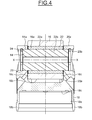
Figure 4 is a cross-section along line IV-IV ofFigure 3 ; -
Figure 5 is a perspective view of a cam follower roller device according to second embodiment of the invention; and -
Figure 6 is a cross-section of the cam follower roller device ofFigure 5 . - A first embodiment of a mechanical cam
follower roller device 10 is illustrated onFigures 1 to 4 , said device may for example be used in a fuel injection pump intended for an internal combustion engine. Thedevice 10 may be used in other applications, for example in a rocker system adapted to control the valves of an internal combustion engine. - The
device 10 comprises an outer casing ortappet body 12, a pin orshaft 14 extending along an axis X-X and mounted on the casing, and aroller 16 supported on theshaft 14 and adapted to press against a cam (not shown) synchronized with the internal combustion engine camshaft or directly against a cam of the said camshaft. - The
outer casing 12 has a tubular form and may be made of stamped metal sheet. Theouter casing 12 comprises afirst end 18 and asecond end 20 opposite to thefirst end 18. - The
first end 18 comprises an outwardly openedrecess 18a designed to cooperate with a pump piston (not shown) delimited by a twolateral walls 18b and aflat seat 18c forming a stroke-transmission plate for the piston head (not shown). Thesecond end 20 comprises an outwardly openedrecess 20a inside which theroller 16 is mounted. - The
roller 16 has abore 16a of cylindrical shape rotatably mounted on an outercylindrical surface 14b of theshaft 14. As illustrated, thedevice 10 further comprises a sleeve or bushing 22 radially disposed between theouter surface 14b of thepin 14 and thebore 16a of theroller 16. An outercylindrical surface 22a of thebushing 22 comes radially into contact with thebore 16a of the roller and aninner bore 22b of saidbushing 22 comes radially into contact with theouter surface 14b of the shaft. Advantageously, thebushing 22 is coated with at least an antifriction and/or wear resistance coating. Thebushing 22 may be coated with a diamond like carbon coating or a black oxide coating as previously described. Preferably, theouter surface 22a of thebushing 22 is coated with the diamond like carbon coating when the black oxide coating is provided on thebore 16a of theroller 16, and thebore 22b of said bushing is coated with the black oxide coating when the diamond like carbon coating is provided on theouter surface 14b of theshaft 14. Alternatively, the device may not comprise a bushing in such a way that thebore 16a of theroller 16 is radially in direct contact with theouter surface 14a of theshaft 14. - As illustrated, the ends 14c of the
shaft 14 project out of theroller 16 and are supported in through-holes 20b formed on thesecond end 20 of thecasing 12 and facing on another. Theshaft 14 is axially maintained in said through-holes 20b by means of awasher 24 radially mounted inside each through-hole 20b. Alternatively, theshaft 14 may be fixed to the casing by push-fitting in said through-holes 20b. Alternatively, theshaft 14 may be fixed to thecasing 12 by any other appropriate means. - The
roller 16 radially projects from theouter surface 20c of thesecond end 20 of thecasing 12. Theroller 16 comprises an outercylindrical surface 16b forming the rolling surface delimited by two parallel lateralradial surfaces 16c perpendicular to the roller rotational. - The
lateral surfaces 16c of the roller come axially into contact withflat sections 20d formed on the inner surface of thesecond end 20 of thecasing 12, in the region of the trough-holes 20b. - On the periphery of the
second end 20 of thecasing 12, fouropenings 26 can be seen, which allow the insertion of aroller 16 of bigger dimensions inside thecasing 12. - As illustrated on
Figures 1 to 4 , theopenings 26 are each located at one end of theflat sections 20d in such a way that two openings face oneend 16c of the outercylindrical surface 16b of theroller 16. The openings are disposed in such a way to be symmetrical compared to the rotational axis X-X and compared to a radial axis (not shown) perpendicular to the rotational axis X-X. Eachopening 26 is made through the thickness of thecasing 12 and has the shape of an outwardly opened slot. - The
casing 12 further comprises on its outer cylindrical surface, agroove 28 designed as a path for the lubricating oil of the engine to reach theroller 16, theshaft 14 and thebushing 22 if there is a bushing. - The embodiment shown on
Figures 5 and6 , in which identical parts are given identical references, differs from the previous embodiment in that the fouropenings 30 provided on the periphery of thesecond end 20 of thecasing 12 have the shape of though-holes. - Thanks to the openings provided at each end of the roller, a roller of bigger dimensions (diameter and axial length) can be inserted inside the casing without increasing the diameter of the casing. The openings provided in the casing allow the insertion of a roller of larger diameter and of larger axial length. Thanks to the increase in the contact surface of the roller, the contact pressure between the roller and the cam can thus be reduced.
- The service life of the cam follower roller device is enhanced even under highly loaded conditions. The cam follower roller device according to the invention can be used with a camshaft, a crankshaft or a balancing shaft.
Claims (10)
- Cam follower roller device, notably for fuel injection pump of an internal combustion engine, comprises a casing (12), a shaft (14) mounted on the casing (12) and a roller (16) rotatably mounted on said shaft (14), characterized in that the casing (12) comprises on its periphery at least four openings (26, 30) made through the thickness of the casing (12) and located in such a way that two openings face one end (16c) of the outer cylindrical surface (16b) of the roller (16).
- Cam follower roller device according to claim 1, in which the outer casing (12) comprises a first end (18) and a second end (20) opposite to the first end (18), said second end comprises an outwardly opened recess (20a) inside which the roller (16) is mounted and through-holes (20b) supporting the ends (14c) of said shaft (14).
- Cam follower roller device according to 2, in which the roller (16) comprises an outer cylindrical surface (16b) forming the rolling surface delimited radially by two lateral surfaces (16c) axially into contact with flat sections (20d) formed on the inner surface of the second end (20) of the casing (12), in the region of the trough-holes (20b).
- Cam follower roller device according to claim 3, in which the openings (26, 30) are each located at one end of the flat sections (20d).
- Cam follower roller device according to any of the preceding claims, in which the openings (26) have the shape of an outwardly opened slot.
- Cam follower roller device according to any of claims 1 to 5, in which the openings (30) have the shape of through-holes.
- Cam follower roller device according to any of the preceding claims, in which the roller (16) radially projects from the outer surface (20c) of the second end (20) of the casing (12).
- Cam follower roller device according to any of the preceding claims, in which at least one of the shaft and the roller is coated with an antifriction and/or wear resistance coating.
- Cam follower roller device according to any of the preceding claims, further comprising a bushing (22) radially interposed between the roller (16) and the shaft (14).
- Cam follower roller device according to claim 9, wherein the outer surface (22a) of the bushing (22) in contact with the bore (16a) of the roller (16) and the bore (22b) of said bushing (22) in contact with the outer cylindrical surface (14b) of the shaft (14) are each coated with an antifriction and/or wear resistance coating.
Priority Applications (3)
| Application Number | Priority Date | Filing Date | Title |
|---|---|---|---|
| EP14165445.9A EP2937566B1 (en) | 2014-04-22 | 2014-04-22 | Cam follower roller device, notably for a fuel injection pump |
| US14/690,890 US9726270B2 (en) | 2014-04-22 | 2015-04-20 | Cam follower roller device, notably for a fuel injection pump |
| CN201510319270.3A CN105179129B (en) | 2014-04-22 | 2015-04-22 | Cam follower roller device, in particular for fuel injection pumps |
Applications Claiming Priority (1)
| Application Number | Priority Date | Filing Date | Title |
|---|---|---|---|
| EP14165445.9A EP2937566B1 (en) | 2014-04-22 | 2014-04-22 | Cam follower roller device, notably for a fuel injection pump |
Publications (2)
| Publication Number | Publication Date |
|---|---|
| EP2937566A1 true EP2937566A1 (en) | 2015-10-28 |
| EP2937566B1 EP2937566B1 (en) | 2016-10-19 |
Family
ID=50513122
Family Applications (1)
| Application Number | Title | Priority Date | Filing Date |
|---|---|---|---|
| EP14165445.9A Active EP2937566B1 (en) | 2014-04-22 | 2014-04-22 | Cam follower roller device, notably for a fuel injection pump |
Country Status (3)
| Country | Link |
|---|---|
| US (1) | US9726270B2 (en) |
| EP (1) | EP2937566B1 (en) |
| CN (1) | CN105179129B (en) |
Cited By (3)
| Publication number | Priority date | Publication date | Assignee | Title |
|---|---|---|---|---|
| EP3173592A1 (en) * | 2015-11-24 | 2017-05-31 | Aktiebolaget SKF | Cam follower roller device with lubricant supply holes and lubricating method |
| EP3179061A1 (en) * | 2015-12-10 | 2017-06-14 | Aktiebolaget SKF | Cam follower roller device with roller |
| EP3181836A1 (en) * | 2015-12-17 | 2017-06-21 | Aktiebolaget SKF | Cam follower roller device |
Families Citing this family (2)
| Publication number | Priority date | Publication date | Assignee | Title |
|---|---|---|---|---|
| DE102024106283A1 (en) * | 2024-03-05 | 2025-09-11 | Schaeffler Technologies AG & Co. KG | Tappet for a high-pressure fuel pump with an axial locking device for its bolt carrying a cam roller |
| DE102024110494A1 (en) * | 2024-04-15 | 2025-10-16 | Schaeffler Technologies AG & Co. KG | Roller tappet for a pump or valve train of an internal combustion engine |
Citations (3)
| Publication number | Priority date | Publication date | Assignee | Title |
|---|---|---|---|---|
| WO2001081727A1 (en) * | 2000-04-21 | 2001-11-01 | Jurij Manfreda | Piston assembly for a radial piston hydraulic motor |
| US20080190237A1 (en) | 2006-12-06 | 2008-08-14 | Schaeffler Kg | Mechanical tappet in particular for a fuel pump of an internal combustion engine |
| DE102012208791A1 (en) * | 2012-05-25 | 2013-11-28 | Schaeffler Technologies AG & Co. KG | Plunger for e.g. high pressure pump, for pumping diesel fuel into quality or quantity-controlled internal combustion engine, has notch-like discharges longitudinally extending at casing, and roller with ring edges projecting into discharges |
Family Cites Families (19)
| Publication number | Priority date | Publication date | Assignee | Title |
|---|---|---|---|---|
| US2152404A (en) * | 1938-06-18 | 1939-03-28 | Eaton Mfg Co | Valve tappet |
| US2152403A (en) * | 1938-06-18 | 1939-03-28 | Eaton Mfg Co | Valve tappet |
| US5188068A (en) * | 1991-02-04 | 1993-02-23 | Crane Cams | Roller tappet |
| US5127374A (en) * | 1991-11-21 | 1992-07-07 | Morel Jr Edward J | Valve lifter |
| WO2004028878A1 (en) * | 2002-09-24 | 2004-04-08 | Continental Teves Ag & Co. Ohg | Supply device |
| DE102005017409A1 (en) * | 2005-04-15 | 2006-10-19 | Schaeffler Kg | Outer part of a switchable tappet |
| DE102006031032A1 (en) * | 2006-07-05 | 2008-01-10 | Schaeffler Kg | Tappet for fuel high pressure pump of internal combustion engine, has cross-hole for supplying lubricant to shell surface and bearing surface, and tappet skirt with outer annular groove that connects cross hole with lubricant supply channel |
| DE102007006320A1 (en) * | 2007-02-08 | 2008-08-14 | Schaeffler Kg | Mechanical roller tappet for an internal combustion engine |
| US20080228275A1 (en) | 2007-03-14 | 2008-09-18 | Heather Cannon | Intervertebral implant component with three points of contact |
| US8464678B1 (en) * | 2007-12-18 | 2013-06-18 | Ed Iskenderian Racing Cams | Roller valve lifter |
| DE102009013130A1 (en) * | 2009-03-13 | 2010-09-16 | Schaeffler Technologies Gmbh & Co. Kg | tappet |
| DE102010030498A1 (en) * | 2010-06-24 | 2011-12-29 | Robert Bosch Gmbh | Pump, in particular high-pressure fuel pump |
| DE102010063351A1 (en) * | 2010-12-17 | 2012-06-21 | Robert Bosch Gmbh | high pressure pump |
| FR2998614A1 (en) * | 2012-11-29 | 2014-05-30 | Skf Ab | CAM FOLLOWER WITH ANTI-ROTATION DEVICE |
| US8616772B1 (en) * | 2013-03-15 | 2013-12-31 | Little Engine, LLC | Conformal wear-resistant bearing assembly |
| EP3002426B1 (en) * | 2014-09-30 | 2017-11-08 | Aktiebolaget SKF | Mechanical system forming a cam follower or a rocker arm |
| EP3026231B1 (en) * | 2014-11-27 | 2020-08-12 | Aktiebolaget SKF | Mechanical system forming a cam follower or a rocker arm, injection pump or valve actuator comprising such a mechanical system and method for manufacturing such a mechanical system |
| EP3026232B1 (en) * | 2014-11-27 | 2020-01-08 | Aktiebolaget SKF | Mechanical system forming a cam follower or a rocker arm, injection pump or valve actuator comprising such a mechanical system and method for manufacturing such a mechanical system |
| EP3056696A1 (en) * | 2015-02-10 | 2016-08-17 | Aktiebolaget SKF | Mechanical system forming a cam follower or a rocker arm, injection pump or valve actuator comprising such a mechanical system and method for manufacturing such a mechanical system |
-
2014
- 2014-04-22 EP EP14165445.9A patent/EP2937566B1/en active Active
-
2015
- 2015-04-20 US US14/690,890 patent/US9726270B2/en active Active
- 2015-04-22 CN CN201510319270.3A patent/CN105179129B/en active Active
Patent Citations (3)
| Publication number | Priority date | Publication date | Assignee | Title |
|---|---|---|---|---|
| WO2001081727A1 (en) * | 2000-04-21 | 2001-11-01 | Jurij Manfreda | Piston assembly for a radial piston hydraulic motor |
| US20080190237A1 (en) | 2006-12-06 | 2008-08-14 | Schaeffler Kg | Mechanical tappet in particular for a fuel pump of an internal combustion engine |
| DE102012208791A1 (en) * | 2012-05-25 | 2013-11-28 | Schaeffler Technologies AG & Co. KG | Plunger for e.g. high pressure pump, for pumping diesel fuel into quality or quantity-controlled internal combustion engine, has notch-like discharges longitudinally extending at casing, and roller with ring edges projecting into discharges |
Cited By (7)
| Publication number | Priority date | Publication date | Assignee | Title |
|---|---|---|---|---|
| EP3173592A1 (en) * | 2015-11-24 | 2017-05-31 | Aktiebolaget SKF | Cam follower roller device with lubricant supply holes and lubricating method |
| US10718240B2 (en) | 2015-11-24 | 2020-07-21 | Aktiebolaget Skf | Cam follower roller device with lubricant supply holes and lubricating method |
| EP3179061A1 (en) * | 2015-12-10 | 2017-06-14 | Aktiebolaget SKF | Cam follower roller device with roller |
| EP3181836A1 (en) * | 2015-12-17 | 2017-06-21 | Aktiebolaget SKF | Cam follower roller device |
| CN106948985A (en) * | 2015-12-17 | 2017-07-14 | 斯凯孚公司 | Cam driven roller arrangement |
| US10072533B2 (en) | 2015-12-17 | 2018-09-11 | Aktiebolaget Skf | Cam follower roller device |
| CN106948985B (en) * | 2015-12-17 | 2020-10-02 | 斯凯孚公司 | Cam Follower Roller |
Also Published As
| Publication number | Publication date |
|---|---|
| US20150300476A1 (en) | 2015-10-22 |
| CN105179129B (en) | 2020-03-24 |
| EP2937566B1 (en) | 2016-10-19 |
| CN105179129A (en) | 2015-12-23 |
| US9726270B2 (en) | 2017-08-08 |
Similar Documents
| Publication | Publication Date | Title |
|---|---|---|
| EP2853738B1 (en) | Mechanical system, injection pump and valve actuator comprising such a mechanical system and manufacturing method | |
| EP2853698B1 (en) | Cam follower, injection pump and valve actuator comprising such a cam follower and manufacturing method | |
| EP3026232B1 (en) | Mechanical system forming a cam follower or a rocker arm, injection pump or valve actuator comprising such a mechanical system and method for manufacturing such a mechanical system | |
| EP2853696B1 (en) | Mechanical system, injection pump and valve actuator comprising such a mechanical system and manufacturing method | |
| EP2937566B1 (en) | Cam follower roller device, notably for a fuel injection pump | |
| EP3073066B1 (en) | Cam follower, injection pump and valve actuator comprising such a cam follower, and manufacturing method | |
| EP3026231B1 (en) | Mechanical system forming a cam follower or a rocker arm, injection pump or valve actuator comprising such a mechanical system and method for manufacturing such a mechanical system | |
| EP2960446A1 (en) | Mechanical system forming a cam follower or a rocker arm | |
| EP2853699B1 (en) | Tappet, injection pump and valve actuator comprising such a tappet and manufacturing method for such a tappet | |
| EP3002425A1 (en) | Mechanical system forming a cam follower or a rocker arm | |
| JP2013167236A (en) | Cam follower device | |
| EP3173592A1 (en) | Cam follower roller device with lubricant supply holes and lubricating method | |
| EP2947307A1 (en) | Cam follower roller device with integrated sealing elements, notably for a fuel injection pump | |
| EP3020932A1 (en) | Mechanical system forming a cam follower or a rocker arm | |
| US10072533B2 (en) | Cam follower roller device | |
| EP3176421A1 (en) | Cam follower roller device with reinforced tappet body | |
| EP2853697B1 (en) | Mechanical system, injection pump and valve actuator comprising such a mechanical system and manufacturing method | |
| EP2672116B1 (en) | Cam follower roller device, notably for a fuel injection pump | |
| EP3002424A1 (en) | Mechanical system forming a cam follower or a rocker arm | |
| EP2806188A1 (en) | Cam follower roller assembly | |
| US20150233459A1 (en) | Cam follower or eccentric follower with roller supported by plain bearing mounting |
Legal Events
| Date | Code | Title | Description |
|---|---|---|---|
| PUAI | Public reference made under article 153(3) epc to a published international application that has entered the european phase |
Free format text: ORIGINAL CODE: 0009012 |
|
| AK | Designated contracting states |
Kind code of ref document: A1 Designated state(s): AL AT BE BG CH CY CZ DE DK EE ES FI FR GB GR HR HU IE IS IT LI LT LU LV MC MK MT NL NO PL PT RO RS SE SI SK SM TR |
|
| AX | Request for extension of the european patent |
Extension state: BA ME |
|
| 17P | Request for examination filed |
Effective date: 20160414 |
|
| GRAP | Despatch of communication of intention to grant a patent |
Free format text: ORIGINAL CODE: EPIDOSNIGR1 |
|
| RIC1 | Information provided on ipc code assigned before grant |
Ipc: F04B 1/04 20060101AFI20160429BHEP |
|
| INTG | Intention to grant announced |
Effective date: 20160607 |
|
| RIN1 | Information on inventor provided before grant (corrected) |
Inventor name: CHAMPALOU, FRANCOIS Inventor name: BERRUET, NICOLAS Inventor name: HAUVESPRE, BENOIT Inventor name: VIAULT, SAMUEL |
|
| GRAS | Grant fee paid |
Free format text: ORIGINAL CODE: EPIDOSNIGR3 |
|
| GRAA | (expected) grant |
Free format text: ORIGINAL CODE: 0009210 |
|
| AK | Designated contracting states |
Kind code of ref document: B1 Designated state(s): AL AT BE BG CH CY CZ DE DK EE ES FI FR GB GR HR HU IE IS IT LI LT LU LV MC MK MT NL NO PL PT RO RS SE SI SK SM TR |
|
| REG | Reference to a national code |
Ref country code: GB Ref legal event code: FG4D |
|
| REG | Reference to a national code |
Ref country code: CH Ref legal event code: EP |
|
| REG | Reference to a national code |
Ref country code: AT Ref legal event code: REF Ref document number: 838594 Country of ref document: AT Kind code of ref document: T Effective date: 20161115 |
|
| REG | Reference to a national code |
Ref country code: IE Ref legal event code: FG4D |
|
| REG | Reference to a national code |
Ref country code: DE Ref legal event code: R096 Ref document number: 602014004295 Country of ref document: DE |
|
| REG | Reference to a national code |
Ref country code: NL Ref legal event code: MP Effective date: 20161019 |
|
| REG | Reference to a national code |
Ref country code: LT Ref legal event code: MG4D |
|
| PG25 | Lapsed in a contracting state [announced via postgrant information from national office to epo] |
Ref country code: LV Free format text: LAPSE BECAUSE OF FAILURE TO SUBMIT A TRANSLATION OF THE DESCRIPTION OR TO PAY THE FEE WITHIN THE PRESCRIBED TIME-LIMIT Effective date: 20161019 |
|
| REG | Reference to a national code |
Ref country code: AT Ref legal event code: MK05 Ref document number: 838594 Country of ref document: AT Kind code of ref document: T Effective date: 20161019 |
|
| PG25 | Lapsed in a contracting state [announced via postgrant information from national office to epo] |
Ref country code: NO Free format text: LAPSE BECAUSE OF FAILURE TO SUBMIT A TRANSLATION OF THE DESCRIPTION OR TO PAY THE FEE WITHIN THE PRESCRIBED TIME-LIMIT Effective date: 20170119 Ref country code: SE Free format text: LAPSE BECAUSE OF FAILURE TO SUBMIT A TRANSLATION OF THE DESCRIPTION OR TO PAY THE FEE WITHIN THE PRESCRIBED TIME-LIMIT Effective date: 20161019 Ref country code: GR Free format text: LAPSE BECAUSE OF FAILURE TO SUBMIT A TRANSLATION OF THE DESCRIPTION OR TO PAY THE FEE WITHIN THE PRESCRIBED TIME-LIMIT Effective date: 20170120 Ref country code: LT Free format text: LAPSE BECAUSE OF FAILURE TO SUBMIT A TRANSLATION OF THE DESCRIPTION OR TO PAY THE FEE WITHIN THE PRESCRIBED TIME-LIMIT Effective date: 20161019 |
|
| PG25 | Lapsed in a contracting state [announced via postgrant information from national office to epo] |
Ref country code: RS Free format text: LAPSE BECAUSE OF FAILURE TO SUBMIT A TRANSLATION OF THE DESCRIPTION OR TO PAY THE FEE WITHIN THE PRESCRIBED TIME-LIMIT Effective date: 20161019 Ref country code: NL Free format text: LAPSE BECAUSE OF FAILURE TO SUBMIT A TRANSLATION OF THE DESCRIPTION OR TO PAY THE FEE WITHIN THE PRESCRIBED TIME-LIMIT Effective date: 20161019 Ref country code: AT Free format text: LAPSE BECAUSE OF FAILURE TO SUBMIT A TRANSLATION OF THE DESCRIPTION OR TO PAY THE FEE WITHIN THE PRESCRIBED TIME-LIMIT Effective date: 20161019 Ref country code: HR Free format text: LAPSE BECAUSE OF FAILURE TO SUBMIT A TRANSLATION OF THE DESCRIPTION OR TO PAY THE FEE WITHIN THE PRESCRIBED TIME-LIMIT Effective date: 20161019 Ref country code: IS Free format text: LAPSE BECAUSE OF FAILURE TO SUBMIT A TRANSLATION OF THE DESCRIPTION OR TO PAY THE FEE WITHIN THE PRESCRIBED TIME-LIMIT Effective date: 20170219 Ref country code: PT Free format text: LAPSE BECAUSE OF FAILURE TO SUBMIT A TRANSLATION OF THE DESCRIPTION OR TO PAY THE FEE WITHIN THE PRESCRIBED TIME-LIMIT Effective date: 20170220 Ref country code: ES Free format text: LAPSE BECAUSE OF FAILURE TO SUBMIT A TRANSLATION OF THE DESCRIPTION OR TO PAY THE FEE WITHIN THE PRESCRIBED TIME-LIMIT Effective date: 20161019 Ref country code: PL Free format text: LAPSE BECAUSE OF FAILURE TO SUBMIT A TRANSLATION OF THE DESCRIPTION OR TO PAY THE FEE WITHIN THE PRESCRIBED TIME-LIMIT Effective date: 20161019 Ref country code: BE Free format text: LAPSE BECAUSE OF FAILURE TO SUBMIT A TRANSLATION OF THE DESCRIPTION OR TO PAY THE FEE WITHIN THE PRESCRIBED TIME-LIMIT Effective date: 20161019 Ref country code: FI Free format text: LAPSE BECAUSE OF FAILURE TO SUBMIT A TRANSLATION OF THE DESCRIPTION OR TO PAY THE FEE WITHIN THE PRESCRIBED TIME-LIMIT Effective date: 20161019 |
|
| REG | Reference to a national code |
Ref country code: DE Ref legal event code: R097 Ref document number: 602014004295 Country of ref document: DE |
|
| PG25 | Lapsed in a contracting state [announced via postgrant information from national office to epo] |
Ref country code: EE Free format text: LAPSE BECAUSE OF FAILURE TO SUBMIT A TRANSLATION OF THE DESCRIPTION OR TO PAY THE FEE WITHIN THE PRESCRIBED TIME-LIMIT Effective date: 20161019 Ref country code: SK Free format text: LAPSE BECAUSE OF FAILURE TO SUBMIT A TRANSLATION OF THE DESCRIPTION OR TO PAY THE FEE WITHIN THE PRESCRIBED TIME-LIMIT Effective date: 20161019 Ref country code: RO Free format text: LAPSE BECAUSE OF FAILURE TO SUBMIT A TRANSLATION OF THE DESCRIPTION OR TO PAY THE FEE WITHIN THE PRESCRIBED TIME-LIMIT Effective date: 20161019 Ref country code: CZ Free format text: LAPSE BECAUSE OF FAILURE TO SUBMIT A TRANSLATION OF THE DESCRIPTION OR TO PAY THE FEE WITHIN THE PRESCRIBED TIME-LIMIT Effective date: 20161019 Ref country code: DK Free format text: LAPSE BECAUSE OF FAILURE TO SUBMIT A TRANSLATION OF THE DESCRIPTION OR TO PAY THE FEE WITHIN THE PRESCRIBED TIME-LIMIT Effective date: 20161019 |
|
| PLBE | No opposition filed within time limit |
Free format text: ORIGINAL CODE: 0009261 |
|
| STAA | Information on the status of an ep patent application or granted ep patent |
Free format text: STATUS: NO OPPOSITION FILED WITHIN TIME LIMIT |
|
| PG25 | Lapsed in a contracting state [announced via postgrant information from national office to epo] |
Ref country code: BG Free format text: LAPSE BECAUSE OF FAILURE TO SUBMIT A TRANSLATION OF THE DESCRIPTION OR TO PAY THE FEE WITHIN THE PRESCRIBED TIME-LIMIT Effective date: 20170119 Ref country code: IT Free format text: LAPSE BECAUSE OF FAILURE TO SUBMIT A TRANSLATION OF THE DESCRIPTION OR TO PAY THE FEE WITHIN THE PRESCRIBED TIME-LIMIT Effective date: 20161019 Ref country code: SM Free format text: LAPSE BECAUSE OF FAILURE TO SUBMIT A TRANSLATION OF THE DESCRIPTION OR TO PAY THE FEE WITHIN THE PRESCRIBED TIME-LIMIT Effective date: 20161019 |
|
| 26N | No opposition filed |
Effective date: 20170720 |
|
| PG25 | Lapsed in a contracting state [announced via postgrant information from national office to epo] |
Ref country code: SI Free format text: LAPSE BECAUSE OF FAILURE TO SUBMIT A TRANSLATION OF THE DESCRIPTION OR TO PAY THE FEE WITHIN THE PRESCRIBED TIME-LIMIT Effective date: 20161019 |
|
| REG | Reference to a national code |
Ref country code: CH Ref legal event code: PL |
|
| REG | Reference to a national code |
Ref country code: IE Ref legal event code: MM4A |
|
| REG | Reference to a national code |
Ref country code: FR Ref legal event code: ST Effective date: 20171229 |
|
| PG25 | Lapsed in a contracting state [announced via postgrant information from national office to epo] |
Ref country code: MC Free format text: LAPSE BECAUSE OF FAILURE TO SUBMIT A TRANSLATION OF THE DESCRIPTION OR TO PAY THE FEE WITHIN THE PRESCRIBED TIME-LIMIT Effective date: 20161019 Ref country code: FR Free format text: LAPSE BECAUSE OF NON-PAYMENT OF DUE FEES Effective date: 20170502 |
|
| PG25 | Lapsed in a contracting state [announced via postgrant information from national office to epo] |
Ref country code: LU Free format text: LAPSE BECAUSE OF NON-PAYMENT OF DUE FEES Effective date: 20170422 Ref country code: LI Free format text: LAPSE BECAUSE OF NON-PAYMENT OF DUE FEES Effective date: 20170430 Ref country code: CH Free format text: LAPSE BECAUSE OF NON-PAYMENT OF DUE FEES Effective date: 20170430 |
|
| PG25 | Lapsed in a contracting state [announced via postgrant information from national office to epo] |
Ref country code: IE Free format text: LAPSE BECAUSE OF NON-PAYMENT OF DUE FEES Effective date: 20170422 |
|
| PG25 | Lapsed in a contracting state [announced via postgrant information from national office to epo] |
Ref country code: MT Free format text: LAPSE BECAUSE OF NON-PAYMENT OF DUE FEES Effective date: 20170422 |
|
| GBPC | Gb: european patent ceased through non-payment of renewal fee |
Effective date: 20180422 |
|
| PG25 | Lapsed in a contracting state [announced via postgrant information from national office to epo] |
Ref country code: GB Free format text: LAPSE BECAUSE OF NON-PAYMENT OF DUE FEES Effective date: 20180422 |
|
| PG25 | Lapsed in a contracting state [announced via postgrant information from national office to epo] |
Ref country code: HU Free format text: LAPSE BECAUSE OF FAILURE TO SUBMIT A TRANSLATION OF THE DESCRIPTION OR TO PAY THE FEE WITHIN THE PRESCRIBED TIME-LIMIT; INVALID AB INITIO Effective date: 20140422 |
|
| PG25 | Lapsed in a contracting state [announced via postgrant information from national office to epo] |
Ref country code: CY Free format text: LAPSE BECAUSE OF FAILURE TO SUBMIT A TRANSLATION OF THE DESCRIPTION OR TO PAY THE FEE WITHIN THE PRESCRIBED TIME-LIMIT Effective date: 20161019 |
|
| PG25 | Lapsed in a contracting state [announced via postgrant information from national office to epo] |
Ref country code: MK Free format text: LAPSE BECAUSE OF FAILURE TO SUBMIT A TRANSLATION OF THE DESCRIPTION OR TO PAY THE FEE WITHIN THE PRESCRIBED TIME-LIMIT Effective date: 20161019 |
|
| PG25 | Lapsed in a contracting state [announced via postgrant information from national office to epo] |
Ref country code: TR Free format text: LAPSE BECAUSE OF FAILURE TO SUBMIT A TRANSLATION OF THE DESCRIPTION OR TO PAY THE FEE WITHIN THE PRESCRIBED TIME-LIMIT Effective date: 20161019 |
|
| PG25 | Lapsed in a contracting state [announced via postgrant information from national office to epo] |
Ref country code: AL Free format text: LAPSE BECAUSE OF FAILURE TO SUBMIT A TRANSLATION OF THE DESCRIPTION OR TO PAY THE FEE WITHIN THE PRESCRIBED TIME-LIMIT Effective date: 20161019 |
|
| P01 | Opt-out of the competence of the unified patent court (upc) registered |
Effective date: 20230513 |
|
| REG | Reference to a national code |
Ref country code: DE Ref legal event code: R082 Ref document number: 602014004295 Country of ref document: DE Representative=s name: SCHONECKE, MITJA, DIPL.-PHYS. DR. RER. NAT., DE Ref country code: DE Ref legal event code: R082 Ref document number: 602014004295 Country of ref document: DE Representative=s name: SCHONECKE, MITJA, DR., DE |
|
| REG | Reference to a national code |
Ref country code: DE Ref legal event code: R082 Ref document number: 602014004295 Country of ref document: DE Representative=s name: SCHONECKE, MITJA, DR., DE |
|
| PGFP | Annual fee paid to national office [announced via postgrant information from national office to epo] |
Ref country code: DE Payment date: 20260421 Year of fee payment: 13 |