EP2937547A1 - Piston for an internal combustion engine - Google Patents
Piston for an internal combustion engine Download PDFInfo
- Publication number
- EP2937547A1 EP2937547A1 EP13834370.2A EP13834370A EP2937547A1 EP 2937547 A1 EP2937547 A1 EP 2937547A1 EP 13834370 A EP13834370 A EP 13834370A EP 2937547 A1 EP2937547 A1 EP 2937547A1
- Authority
- EP
- European Patent Office
- Prior art keywords
- piston
- segment
- defines
- radial bore
- radial
- Prior art date
- Legal status (The legal status is an assumption and is not a legal conclusion. Google has not performed a legal analysis and makes no representation as to the accuracy of the status listed.)
- Withdrawn
Links
- 238000002485 combustion reaction Methods 0.000 title claims abstract description 16
- 230000006835 compression Effects 0.000 claims abstract description 9
- 238000007906 compression Methods 0.000 claims abstract description 9
- 230000003014 reinforcing effect Effects 0.000 claims description 5
- 230000003247 decreasing effect Effects 0.000 claims description 2
- 230000009467 reduction Effects 0.000 description 5
- 230000006872 improvement Effects 0.000 description 3
- 238000005304 joining Methods 0.000 description 2
- 239000000203 mixture Substances 0.000 description 2
- 230000002093 peripheral effect Effects 0.000 description 2
- 230000008859 change Effects 0.000 description 1
- 230000007423 decrease Effects 0.000 description 1
- 230000000694 effects Effects 0.000 description 1
- 239000003344 environmental pollutant Substances 0.000 description 1
- 238000004880 explosion Methods 0.000 description 1
- 239000012530 fluid Substances 0.000 description 1
- 239000000446 fuel Substances 0.000 description 1
- 238000005461 lubrication Methods 0.000 description 1
- 238000004519 manufacturing process Methods 0.000 description 1
- 239000007769 metal material Substances 0.000 description 1
- 238000005457 optimization Methods 0.000 description 1
- 231100000719 pollutant Toxicity 0.000 description 1
- 238000004088 simulation Methods 0.000 description 1
- 238000005549 size reduction Methods 0.000 description 1
- 230000000930 thermomechanical effect Effects 0.000 description 1
Images


Classifications
-
- F—MECHANICAL ENGINEERING; LIGHTING; HEATING; WEAPONS; BLASTING
- F02—COMBUSTION ENGINES; HOT-GAS OR COMBUSTION-PRODUCT ENGINE PLANTS
- F02F—CYLINDERS, PISTONS OR CASINGS, FOR COMBUSTION ENGINES; ARRANGEMENTS OF SEALINGS IN COMBUSTION ENGINES
- F02F3/00—Pistons
- F02F3/26—Pistons having combustion chamber in piston head
-
- F—MECHANICAL ENGINEERING; LIGHTING; HEATING; WEAPONS; BLASTING
- F02—COMBUSTION ENGINES; HOT-GAS OR COMBUSTION-PRODUCT ENGINE PLANTS
- F02F—CYLINDERS, PISTONS OR CASINGS, FOR COMBUSTION ENGINES; ARRANGEMENTS OF SEALINGS IN COMBUSTION ENGINES
- F02F3/00—Pistons
- F02F3/02—Pistons having means for accommodating or controlling heat expansion
-
- F—MECHANICAL ENGINEERING; LIGHTING; HEATING; WEAPONS; BLASTING
- F02—COMBUSTION ENGINES; HOT-GAS OR COMBUSTION-PRODUCT ENGINE PLANTS
- F02F—CYLINDERS, PISTONS OR CASINGS, FOR COMBUSTION ENGINES; ARRANGEMENTS OF SEALINGS IN COMBUSTION ENGINES
- F02F3/00—Pistons
- F02F3/0015—Multi-part pistons
-
- F—MECHANICAL ENGINEERING; LIGHTING; HEATING; WEAPONS; BLASTING
- F02—COMBUSTION ENGINES; HOT-GAS OR COMBUSTION-PRODUCT ENGINE PLANTS
- F02F—CYLINDERS, PISTONS OR CASINGS, FOR COMBUSTION ENGINES; ARRANGEMENTS OF SEALINGS IN COMBUSTION ENGINES
- F02F3/00—Pistons
- F02F3/16—Pistons having cooling means
- F02F3/20—Pistons having cooling means the means being a fluid flowing through or along piston
- F02F3/22—Pistons having cooling means the means being a fluid flowing through or along piston the fluid being liquid
Definitions
- a piston for an internal combustion engine such as that used in engines that operate according to the Otto or Diesel cycles, has a generally cylindrical shape having an upper portion or head defining the combustion chamber together with the cylinder head and the engine block, a cylindrical side wall or skirt comprising at least two annular cavities for positioning the piston rings (compression, intermediate, and oil scraper), and a radial boss for positioning the piston pin, which pivotally fixes it to the rod.
- Patent document DE 10145589 relates to a piston for an internal combustion engine the innovation of which, again, is in the connecting walls of the skirt segments with the piston central region, where the bore for positioning the piston pin is located.
- the connecting walls are convex in the area of the lower peripheral edges and concave or straight in the upper area, just below the ring grooves.
- the walls of the bore for positioning the piston pin may have a constant or variable thickness.
- Patent document JP 11-036978 relates to a piston capable of efficiently distribute the forces on the load side.
- the skirt portion on the load side is thicker, and its thickness is greater in the portion adjacent to the ring grooves and gradually decreases.
- Patent document JP 2008-286030 relates to a piston of an internal combustion engine capable of resisting the stresses of radial deformation on the portions of the skirt free end.
- an internal wall is provided in the form of a plate that anchors both walls joining the two skirt side sections with the bore for positioning the pin, thus ensuring the structural strength of the part.
- the present invention relates to a piston of an internal combustion engine, the constructive geometry of which provides advantages such as increased strength, lower mass and reduced friction, thus optimizing the operation of the internal combustion engine equipped therewith.
- the present invention relates to a piston for an internal combustion engine 1, particularly designed for use in an engine which operates according to the Otto and Diesel cycles.
- the piston is designed for use in Diesel engines, as is the case of the embodiment illustrated in the figures; but conceptually nothing prevents the piston to be used in an Otto cycle engine, such as a gas engine or even in other uses, such as in a two-stroke engine or a fluid compressor.
- each of the first and second side segments 3", 3" has a free end 30, opposite the top portion 2 of which they protrude from, the thickness of the at least first and second side segments 3', 3" decreasing from top portion 2 toward free end 30.
- Piston 1 further comprises a substantially cylindrical portion defining a radial bore 4 positioned substantially parallel, and in the lower portion relative to the top portion 2, for positioning a piston pin/rod, which will allow the angular movement of the rod relative to the piston.
- piston 1, object of the present invention comprises at least the first two structural walls 5' which perform the connection between the first segment of the side portion 3' with the portion that defines the radial bore 4, and at least two second structural walls 5" making the connection between the second segment of side portion 3" with the portion defining the radial hole 4.
- first two structural walls 5' are divergent and second walls 5" are convergent toward the substantially cylindrical portion which defines the radial bore 4, they are essentially and substantially straight at the free end 30.
- the wall 5' has a variable and increasing thickness towards 3'.
- the outer surface of the wall 5' can be parallel or divergent with respect to bore 4 and the inner wall surface 5' is necessarily divergent with respect to bore 4.
- Wall 5" has a constant thickness. Regarding the upper portion 2 (top), walls 5', 5" are convergent.
- the shape of the cavity and the shape and amount(s) of the respective access window(s) 7' can vary freely.
- piston 1 object of the present invention, is the provision of a cavity 20 in the top portion 2 that defines the engine combustion chamber when the piston is positioned inside the cylinder.
Landscapes
- Engineering & Computer Science (AREA)
- Chemical & Material Sciences (AREA)
- Combustion & Propulsion (AREA)
- Mechanical Engineering (AREA)
- General Engineering & Computer Science (AREA)
- Physics & Mathematics (AREA)
- Fluid Mechanics (AREA)
- Pistons, Piston Rings, And Cylinders (AREA)
Abstract
A piston for an internal combustion engine is provided with a top portion (2) substantially circular from which outer perimeter protrudes a side portion (3) comprising at least a first segment (3') positioned on the portion of the piston that undergoes a greater radial compressive stress (TS) and at least a second segment (3") located in the opposite portion of the piston which undergoes a lower stress radial compression (ATS), the piston further comprising a substantially cylindrical portion which defines a radial bore (4) positioned substantially parallel, and in the lower portion relative to the head portion (2) for positioning a piston/rod pin and at least two first structural walls (5') making the connection between the first segment of the side portion (3') with the portion which defines the radial bore (4) and at least two second structural walls (5') making the connection between the second side segment (3") with the portion which defines the radial bore (4), wherein the first structural walls (5') are substantially divergent toward the substantially cylindrical portion which defines the radial bore (4) and the second structural walls (5") are substantially convergent toward the substantially cylindrical portion which defines the radial bore (4).
Description
- The present invention relates to a piston for an internal combustion engine, designed particularly for an internal combustion engine that operates on the Otto or Diesel cycle, the constructive geometry of which provides advantages such as increased strength, lower mass and reduced friction, thus optimizing the operation of the internal combustion engine equipped therewith.
- A piston for an internal combustion engine such as that used in engines that operate according to the Otto or Diesel cycles, has a generally cylindrical shape having an upper portion or head defining the combustion chamber together with the cylinder head and the engine block, a cylindrical side wall or skirt comprising at least two annular cavities for positioning the piston rings (compression, intermediate, and oil scraper), and a radial boss for positioning the piston pin, which pivotally fixes it to the rod.
- In older engines, the pistons feature an almost perfectly cylindrical shape; but the technological improvement and the ever-increasing high power demands, low consumption and pollutant emission limits increasingly restrictive led to a considerable improvement in the shape of this component.
- Thus, the most modern engines have pistons whose geometric shape, although obviously being cylindrical to be cooperative with the cylinder inside which it will move a million times, are quite different in elements such as radial bore, skirt, head, grooves and other reinforcing elements.
- In essence, designers seek to reduce the size of the side skirt in order to reduce weight and friction, while maintaining the properties of the structural strength of the part. A number of solutions have been proposed recently, some of the most relevant are briefly commented below.
- Patent document
US 2011/0168124 relates to a piston in which the improvement resides in the specific geometry of the walls that join the two sections of the side skirt (on the sides of the load, called thrust side - TS and on the unloaded side, called anti-thrust side - ATS) with the central portion of the piston, where the bore for positioning the pin is located. According to the teachings of this invention, the walls that connect the side skirt in the TS with the bore are arched, while the walls that effect the connection of the side skirt in the ATS are substantially straight and parallel to each other. As a result of this geometry, the arched side walls in the ATS side have greater elasticity, which is important since they do not suffer as high shear forces and define the stroke of the movement of the piston. - Patent document
DE 10145589 relates to a piston for an internal combustion engine the innovation of which, again, is in the connecting walls of the skirt segments with the piston central region, where the bore for positioning the piston pin is located. The connecting walls are convex in the area of the lower peripheral edges and concave or straight in the upper area, just below the ring grooves. The walls of the bore for positioning the piston pin may have a constant or variable thickness. - Patent document
JP 11-036978 - Patent document
JP 2008-286030 - Finally, patent document
JP 2008-309118 - So far, therefore, no piston had been developed that has reached the goals of lower wear, durability and lightness from the innovative geometric changes made by the applicant, after extensive studies and simulations.
- The present invention relates to a piston of an internal combustion engine, the constructive geometry of which provides advantages such as increased strength, lower mass and reduced friction, thus optimizing the operation of the internal combustion engine equipped therewith.
- The objects of the present invention are reached by a piston for an internal combustion engine provided with a substantially circular top portion from which outer circumference protrudes a side portion comprising at least a first segment positioned at the portion of the piston which undergoes greater degree of radial compression and at least a second portion positioned on the opposite portion of the piston, which undergoes a smaller radial compression force. The piston further comprises a substantially cylindrical portion defining a radial bore positioned substantially parallel in the lower portion relative to the top portion, for positioning a piston pin/rod and at least two structural walls making the connection between the first segment of the side portion defining the radial bore and at least two second structural walls making the connection between the second segment of the side portion with the portion which defines the radial bore. The first structural walls are substantially divergent toward the substantially cylindrical portion defining the radial bore and the second structural walls are substantially convergent toward the substantially cylindrical portion defining the radial bore.
- The present invention will be further described in more details based on one example of realization represented in the drawings. The figures show:
-
Figure 1 - is a first side view of a possible embodiment of the piston engine object of the present invention. -
Figure 2 - is a second side view of the piston illustrated inFigure 1 , lagging by 90° in relation to it. -
Figure 3 - is a sectional view of the piston in the position illustrated inFigure 1 . -
Figure 4 - is a sectional view of the piston in the position illustrated inFigure 2 . -
Figure 5 - is a bottom perspective view of the piston illustrated inFigures 1 to 4 . -
Figure 6 - is a bottom view of the piston illustrated inFigures 1 to 5 . -
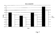
Figure 7 - is a graph comparing the reduction in mass/weight. - According to a preferred embodiment and, as can be seen from
Figure 1 , the present invention relates to a piston for aninternal combustion engine 1, particularly designed for use in an engine which operates according to the Otto and Diesel cycles. In a preferred embodiment, the piston is designed for use in Diesel engines, as is the case of the embodiment illustrated in the figures; but conceptually nothing prevents the piston to be used in an Otto cycle engine, such as a gas engine or even in other uses, such as in a two-stroke engine or a fluid compressor. - As the vast majority of currently known pistons,
piston 1, object of the present invention, is provided with a top portion 2 (usually called "upper" portion, being the one that comes into contact with the air-fuel mixture) substantially circular from an outer circumference of which protrudes aside portion 3 comprising at least two (but in practice, three or four) annular cavities for positioning the piston rings which are split into the compression rings, intermediate or second groove rings and oil-film control or scraper rings. Because it is not relevant in defining the scope of protection of the present piston, the shape, number and positioning of the annular cavities may vary freely. - The side portion of
piston 1 can be continuous or segmented and, in a preferable but not mandatory manner, comprises at least a first segment 3' positioned on the portion of the piston suffers the greatest stresses of radial compression, called TS, thrust side, (arising from the explosion of the fuel-air mixture, which moves the piston against the inner surface of the jacket (not shown) in the direction of the crankshaft (not shown), causing a change in the angle of the connecting rod which ultimately generates a non-negligible component of radial force). It is further provided at least onesecond segment 3" positioned in the opposite region of the piston, lagging 180°, and which does not undergo radial compression stresses in that magnitude, called ATS (anti-thrust side). - Because of the difference in radial force they are subjected to, the
first side segment 3" has an average thickness greater than the average thickness of thesecond side segment 3". If measured at points corresponding to each of the segments, the thickness of the first segment 3' will always be greater than the thickness of thesecond segment 3". - On the other hand, it is the
second side segment 3" the one responsible for guiding the movement of piston inside the cylinder, especially in the compression and exhaust strokes, which has the width (arc) higher than the first side segment 3'. In other words, the width of the first side segment 3' is smaller than the width of thesecond side segment 3". - In a preferred but not mandatory manner, each of the first and
second side segments 3", 3" has afree end 30, opposite thetop portion 2 of which they protrude from, the thickness of the at least first andsecond side segments 3', 3" decreasing fromtop portion 2 towardfree end 30. -
Piston 1 further comprises a substantially cylindrical portion defining aradial bore 4 positioned substantially parallel, and in the lower portion relative to thetop portion 2, for positioning a piston pin/rod, which will allow the angular movement of the rod relative to the piston. - There are also
side walls 5', 5" joining the first andsecond side segments 3', 3" with the substantially cylindrical portion defining theradial bore 4, with the primary function of providing shape structure and mechanical strength topiston 1. Side walls exist in most modern pistons, but the configuration they assume inpiston 1, object of the present invention, is completely novel and innovative, providing it with properties of strength and lightness. - In essence, whatever its specific configuration,
piston 1, object of the present invention, comprises at least the first two structural walls 5' which perform the connection between the first segment of the side portion 3' with the portion that defines theradial bore 4, and at least two secondstructural walls 5" making the connection between the second segment ofside portion 3" with the portion defining theradial hole 4. - The first structural walls 5' are substantially divergent toward the substantially cylindrical portion defining the
radial bore 4 and the secondstructural walls 5" are substantially convergent toward the substantially cylindrical portion defining theradial bore 4.Walls 5', 5" can be seen, particularly, inFigures 5 and 6 . - In addition to the fact that the first two structural walls 5' are divergent and
second walls 5" are convergent toward the substantially cylindrical portion which defines theradial bore 4, they are essentially and substantially straight at thefree end 30. The wall 5' has a variable and increasing thickness towards 3'. The outer surface of the wall 5' can be parallel or divergent with respect tobore 4 and the inner wall surface 5' is necessarily divergent with respect tobore 4.Wall 5" has a constant thickness. Regarding the upper portion 2 (top),walls 5', 5" are convergent. - Its inclination, combined with the fact that they are substantially straight and respectively convergent/divergent causes the first and second
structural walls 5', 5" are very important in the improved structural behavior ofpiston 1, object of the present invention over those currently known. - Optionally, the piston comprises at least one reinforcing
element 6 for increasing strength in the cooperation region betweenwalls 5', 5" andtop portion 2. In a preferred manner, four reinforcing elements (which may be of different dimensions/sizes) are provided, which increase the rigidity of the piston and helps to prevent the peripheral portion from "twisting" laterally on the aforementioned radial bore, especially when the engine equipped withpiston 1 has high thermo-mechanical loading, as in the case of a piston designed for a Diesel engine. The reinforcing elements can be seen inFigure 1 . - Still optionally, a
cavity 7 is provided adjacent to the cooperation region between the portion which defines theradial bore 4 and thetop portion 2, the cavity having at least one access window 7'. This cavity is used to allow for an oil flow in the inner region of the piston, which is important to reduce the temperature of the top portion and vicinity. -
Cavity 7 being provided, one can anticipate a branch in the engine lubrication circuit to create an oil flow there, thus removing the heat. - Anyway, and even to be an optional characteristic, the shape of the cavity and the shape and amount(s) of the respective access window(s) 7' can vary freely.
- Finally, another option, but not a limiting characteristic of
piston 1, object of the present invention, is the provision of acavity 20 in thetop portion 2 that defines the engine combustion chamber when the piston is positioned inside the cylinder. - Due to the above characteristics,
current piston 1 has a number of advantages over the currently existing pistons, such as increased strength (due to the optimized geometry, with particular regard to the first and secondstructural walls 5', 5"), mass reduction (due to the size reduction and the thickness of the various parts of piston 1), friction reduction. - The present invention allows, through its modified geometry, to achieve greater mass reductions through thickness optimizations in regions where conventional geometry does not permit it, which is achieved by definition of the manufacturing process or commitment of the changed region. The present invention makes it possible to achieve mass reductions above 12%, without compromising its application ability.
- Evidently,
piston 1 can be made of any necessary or desirable metallic or non-metallic material. - After one example of a preferred embodiment has been described, it should be understood that the scope of the present invention encompasses other possible embodiments and is limited only by the content of the appended claims, which include their possible equivalents.
Claims (7)
- A piston for an internal combustion engine provided with a top portion (2) substantially circular from which outer perimeter protrudes a side portion (3) comprising at least a first segment (3') positioned on the portion of the piston that undergoes a greater radial compressive stress (TS) and at least a second segment (3") located in the opposite portion of the piston which undergoes a lower stress radial compression (ATS), the piston further comprising a substantially cylindrical portion defining a radial bore (4) positioned substantially parallel, and in the lower portion relative to the head portion (2) for positioning a piston/rod pin and at least two first structural walls (5') making the connection between the first segment of the side portion (3') with the portion which defines the radial bore (4) and at least two second structural walls (5') making the connection between the second side segment (3") with the portion which defines the radial bore (4), the piston being characterized in that:- the first structural walls (5') are substantially divergent toward the substantially cylindrical portion which defines the radial bore (4);- the second structural walls (5") are substantially convergent toward the substantially cylindrical portion which defines the radial bore (4).
- The piston according to claim 1, characterized in that each of the first and second side segments (3', 3") has a free end (30), opposite the top portion (2) from which they protrude, the thickness of the at least first and second side segments (3', 3") decreasing from the top portion (2) toward the free end (30).
- The piston according to claim 1 or 2, characterized in that the average thickness of the first side segment (3') is greater than the average thickness of the second side segment (3").
- The piston according to claim 1, 2 or 3, characterized in that the width of the first side segment (3') is lower than the width of the second side segment (3").
- The piston according to one of the preceding claims, characterized in that it comprises at least one reinforcing element (6) for increasing the strength in the cooperation region between the walls (5', 5") and the top portion (2).
- The piston according to one of the preceding claims, characterized in that it comprises at least one cavity (7) adjacent to the cooperation region between the portion which defines the radial bore (4) and the top portion (2), the cavity having at least one access window (7').
- The piston according to one of the preceding claims, characterized in that it comprises at least one cavity (20) at the top portion (2) which defines the engine combustion chamber when the piston is positioned inside the cylinder.
Applications Claiming Priority (2)
| Application Number | Priority Date | Filing Date | Title |
|---|---|---|---|
| BRBR102012032765-1A BR102012032765A2 (en) | 2012-12-20 | 2012-12-20 | INTERNAL COMBUSTION ENGINE PISTON |
| PCT/BR2013/000578 WO2014094096A1 (en) | 2012-12-20 | 2013-12-19 | Piston for an internal combustion engine |
Publications (1)
| Publication Number | Publication Date |
|---|---|
| EP2937547A1 true EP2937547A1 (en) | 2015-10-28 |
Family
ID=50230824
Family Applications (1)
| Application Number | Title | Priority Date | Filing Date |
|---|---|---|---|
| EP13834370.2A Withdrawn EP2937547A1 (en) | 2012-12-20 | 2013-12-19 | Piston for an internal combustion engine |
Country Status (6)
| Country | Link |
|---|---|
| US (1) | US20150330329A1 (en) |
| EP (1) | EP2937547A1 (en) |
| JP (1) | JP2016502025A (en) |
| CN (1) | CN104870794A (en) |
| BR (1) | BR102012032765A2 (en) |
| WO (1) | WO2014094096A1 (en) |
Families Citing this family (1)
| Publication number | Priority date | Publication date | Assignee | Title |
|---|---|---|---|---|
| DE102019209248A1 (en) | 2019-06-26 | 2020-12-31 | Federal-Mogul Nürnberg GmbH | Pistons for an internal combustion engine |
Family Cites Families (10)
| Publication number | Priority date | Publication date | Assignee | Title |
|---|---|---|---|---|
| DE1014558B (en) | 1955-03-12 | 1957-08-29 | Roland Offsetmaschf | Gripper device on sheet conveying devices, which take over sheets from the printing cylinder of sheet-fed printing machines or transfer them to him |
| JPH0299245U (en) * | 1989-01-24 | 1990-08-07 | ||
| JPH1136978A (en) | 1997-07-16 | 1999-02-09 | Unisia Jecs Corp | Piston for internal combustion engine |
| JP2002317691A (en) * | 2001-04-19 | 2002-10-31 | Unisia Jecs Corp | Internal combustion engine piston |
| JP4692512B2 (en) | 2007-05-15 | 2011-06-01 | トヨタ自動車株式会社 | Piston and internal combustion engine |
| JP4661831B2 (en) | 2007-06-15 | 2011-03-30 | トヨタ自動車株式会社 | Piston and internal combustion engine |
| AT505592B1 (en) * | 2007-07-06 | 2009-04-15 | Mahle Kinig Kommanditgesellsch | PISTON |
| DE102008002536B4 (en) | 2008-06-19 | 2015-02-12 | Federal-Mogul Nürnberg GmbH | Piston for an internal combustion engine |
| DE102009032379A1 (en) * | 2008-08-13 | 2010-02-18 | Mahle International Gmbh | Piston for an internal combustion engine |
| DE102012203570A1 (en) * | 2012-03-07 | 2013-09-12 | Mahle International Gmbh | Cast light metal piston, especially an aluminum piston |
-
2012
- 2012-12-20 BR BRBR102012032765-1A patent/BR102012032765A2/en not_active IP Right Cessation
-
2013
- 2013-12-19 CN CN201380066681.5A patent/CN104870794A/en active Pending
- 2013-12-19 JP JP2015548115A patent/JP2016502025A/en active Pending
- 2013-12-19 EP EP13834370.2A patent/EP2937547A1/en not_active Withdrawn
- 2013-12-19 WO PCT/BR2013/000578 patent/WO2014094096A1/en not_active Ceased
- 2013-12-19 US US14/654,509 patent/US20150330329A1/en not_active Abandoned
Non-Patent Citations (1)
| Title |
|---|
| See references of WO2014094096A1 * |
Also Published As
| Publication number | Publication date |
|---|---|
| BR102012032765A2 (en) | 2014-09-30 |
| WO2014094096A1 (en) | 2014-06-26 |
| JP2016502025A (en) | 2016-01-21 |
| US20150330329A1 (en) | 2015-11-19 |
| CN104870794A (en) | 2015-08-26 |
Similar Documents
| Publication | Publication Date | Title |
|---|---|---|
| KR102068372B1 (en) | Engine piston | |
| US8220432B2 (en) | Internal combustion engine piston | |
| US9739233B2 (en) | Piston of internal combustion engine | |
| US8387585B2 (en) | Piston of an internal combustion engine with an increased inclination of the box walls of the piston | |
| CN107636276B (en) | Four-stroke internal combustion engine and piston for the same | |
| CN110506173B (en) | Pistons and piston rings for internal combustion engines | |
| EP3368800B1 (en) | Piston, oil control ring therefor and method of construction thereof | |
| EP2937547A1 (en) | Piston for an internal combustion engine | |
| CN101297138B (en) | Piston | |
| JP6299949B2 (en) | Piston for internal combustion engine | |
| CN112204240A (en) | Cast pistons for internal combustion engines made of iron-based materials | |
| JP6206191B2 (en) | Piston of internal combustion engine | |
| US8443715B2 (en) | Piston-pin bore dimensions for a piston of an internal combustion engine | |
| WO2003016757A1 (en) | Piston for an internal combustion engine | |
| JP5307209B2 (en) | Piston of internal combustion engine | |
| EP2647887B1 (en) | Piston with active structure | |
| WO2018216503A1 (en) | Piston for internal combustion engine | |
| KR20120062831A (en) | Monobloc piston with a low friction skirt | |
| JP2026007698A (en) | Pistons for internal combustion engines | |
| CN107850004A (en) | Piston for internal combustion engine | |
| JPS6055700B2 (en) | Piston for internal combustion engine | |
| JP2009257199A (en) | Piston ring structure for internal combustion engine | |
| JP2006257887A (en) | Piston for internal combustion engine |
Legal Events
| Date | Code | Title | Description |
|---|---|---|---|
| PUAI | Public reference made under article 153(3) epc to a published international application that has entered the european phase |
Free format text: ORIGINAL CODE: 0009012 |
|
| 17P | Request for examination filed |
Effective date: 20150608 |
|
| AK | Designated contracting states |
Kind code of ref document: A1 Designated state(s): AL AT BE BG CH CY CZ DE DK EE ES FI FR GB GR HR HU IE IS IT LI LT LU LV MC MK MT NL NO PL PT RO RS SE SI SK SM TR |
|
| AX | Request for extension of the european patent |
Extension state: BA ME |
|
| DAX | Request for extension of the european patent (deleted) | ||
| STAA | Information on the status of an ep patent application or granted ep patent |
Free format text: STATUS: THE APPLICATION HAS BEEN WITHDRAWN |
|
| 18W | Application withdrawn |
Effective date: 20180914 |