EP2937469A1 - Method and apparatus for controlling engine of wheel loader - Google Patents
Method and apparatus for controlling engine of wheel loader Download PDFInfo
- Publication number
- EP2937469A1 EP2937469A1 EP13865373.8A EP13865373A EP2937469A1 EP 2937469 A1 EP2937469 A1 EP 2937469A1 EP 13865373 A EP13865373 A EP 13865373A EP 2937469 A1 EP2937469 A1 EP 2937469A1
- Authority
- EP
- European Patent Office
- Prior art keywords
- engine
- boom
- vehicle
- mode
- sensor
- Prior art date
- Legal status (The legal status is an assumption and is not a legal conclusion. Google has not performed a legal analysis and makes no representation as to the accuracy of the status listed.)
- Granted
Links
Images

Classifications
-
- E—FIXED CONSTRUCTIONS
- E02—HYDRAULIC ENGINEERING; FOUNDATIONS; SOIL SHIFTING
- E02F—DREDGING; SOIL-SHIFTING
- E02F9/00—Component parts of dredgers or soil-shifting machines, not restricted to one of the kinds covered by groups E02F3/00 - E02F7/00
- E02F9/20—Drives; Control devices
- E02F9/22—Hydraulic or pneumatic drives
- E02F9/2246—Control of prime movers, e.g. depending on the hydraulic load of work tools
-
- E—FIXED CONSTRUCTIONS
- E02—HYDRAULIC ENGINEERING; FOUNDATIONS; SOIL SHIFTING
- E02F—DREDGING; SOIL-SHIFTING
- E02F9/00—Component parts of dredgers or soil-shifting machines, not restricted to one of the kinds covered by groups E02F3/00 - E02F7/00
- E02F9/20—Drives; Control devices
-
- E—FIXED CONSTRUCTIONS
- E02—HYDRAULIC ENGINEERING; FOUNDATIONS; SOIL SHIFTING
- E02F—DREDGING; SOIL-SHIFTING
- E02F9/00—Component parts of dredgers or soil-shifting machines, not restricted to one of the kinds covered by groups E02F3/00 - E02F7/00
- E02F9/20—Drives; Control devices
- E02F9/2058—Electric or electro-mechanical or mechanical control devices of vehicle sub-units
- E02F9/2062—Control of propulsion units
- E02F9/2066—Control of propulsion units of the type combustion engines
-
- F—MECHANICAL ENGINEERING; LIGHTING; HEATING; WEAPONS; BLASTING
- F02—COMBUSTION ENGINES; HOT-GAS OR COMBUSTION-PRODUCT ENGINE PLANTS
- F02D—CONTROLLING COMBUSTION ENGINES
- F02D2200/00—Input parameters for engine control
- F02D2200/50—Input parameters for engine control said parameters being related to the vehicle or its components
- F02D2200/501—Vehicle speed
-
- F—MECHANICAL ENGINEERING; LIGHTING; HEATING; WEAPONS; BLASTING
- F02—COMBUSTION ENGINES; HOT-GAS OR COMBUSTION-PRODUCT ENGINE PLANTS
- F02D—CONTROLLING COMBUSTION ENGINES
- F02D29/00—Controlling engines, such controlling being peculiar to the devices driven thereby, the devices being other than parts or accessories essential to engine operation, e.g. controlling of engines by signals external thereto
- F02D29/04—Controlling engines, such controlling being peculiar to the devices driven thereby, the devices being other than parts or accessories essential to engine operation, e.g. controlling of engines by signals external thereto peculiar to engines driving pumps
-
- F—MECHANICAL ENGINEERING; LIGHTING; HEATING; WEAPONS; BLASTING
- F02—COMBUSTION ENGINES; HOT-GAS OR COMBUSTION-PRODUCT ENGINE PLANTS
- F02D—CONTROLLING COMBUSTION ENGINES
- F02D41/00—Electrical control of supply of combustible mixture or its constituents
- F02D41/02—Circuit arrangements for generating control signals
- F02D41/021—Introducing corrections for particular conditions exterior to the engine
Definitions
- work of a wheel loader is performed by repeating a process of excavating loading materials, loading the loading materials and moving the loading materials to a destination, unloading the loading materials, and then going back to a place where the loading materials are located.
- an apparatus for controlling an engine of a wheel loader includes: a sensor unit configured to sense vehicle information and working machine information; a vehicle control unit configured to select a working condition according to a priority of the vehicle information and the working machine information sensed by using the sensor unit, select an engine mode corresponding to the selected working condition, and output an engine mode signal representing the selected engine mode; and an engine control unit configured to control the engine output according to the engine mode signal output from the vehicle control unit.
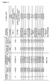
- FIG. 1 is a table illustrating classification of working conditions according to a plurality of pieces of sensing information, and engine modes corresponding to respective working conditions.
- each predetermined reference value may be differently set depending on equipment.
- a working condition according to the present disclosure may be classified into 'heavy/load', 'digging', 'dumping', 'forward/empty', 'load carry', 'reverse/empty', 'previous mode maintenance', and the like.
- an engine mode is divided into a power mode, an economic mode, and a normal mode according to a characteristic of working in an industrial vehicle mounted with a transmission, such as a wheel loader.
- the power mode is a mode emphasizing driving force
- the economic mode is a mode emphasizing a fuel efficiency aspect
- the normal mode which is a generally used mode, is a mode in which fuel efficiency and driving force are appropriately combined.
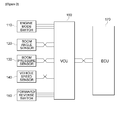
- FIG. 2 is a block diagram illustrating a schematic configuration of an apparatus for controlling an engine of a wheel loader according to an exemplary embodiment of the present disclosure.
- the apparatus for controlling the engine of the wheel loader includes an engine mode switch 110, a boom angle sensor 120, a boom pressure sensor 130, a vehicle speed sensor 140, a forward and reverse switch 150, a vehicle control unit (VCU) 160, an engine control unit (ECU) 170, and the like.
- VCU vehicle control unit
- ECU engine control unit
- the engine mode switch 110 selects any one engine mode among a power mode, an economic mode, a normal mode, and an auto mode.
- the boom angle sensor 120 senses an angle of a boom.
- the VCU 160 selects a working condition according to the angle of the boom sensed by the boom angle sensor 120, the pressure of the boom sensed by the boom pressure sensor 130, the speed of the vehicle sensed by the vehicle speed sensor 140, and the position of the forward/reverse lever sensed by the forward/reverse switch 150, selects an engine mode corresponding to the selected working condition, and outputs an engine mode signal corresponding to the selected engine mode.
- the VCU 160 selects any one engine mode among the power mode, the economic mode, and the normal mode.
- the VCU 160 determines that there is no load, and selects the economic mode.
- the VCU 160 determines that there is a load, and selects the normal mode.
- the ECU 170 changes an RPM torque value of an engine output according to the engine mode signal output from the VCU 160 to control the engine output.
- FIG. 3 is a flowchart illustrating a method of controlling an engine of a wheel loader according to an exemplary embodiment of the present disclosure.
Landscapes
- Engineering & Computer Science (AREA)
- General Engineering & Computer Science (AREA)
- Mining & Mineral Resources (AREA)
- Civil Engineering (AREA)
- Structural Engineering (AREA)
- Chemical & Material Sciences (AREA)
- Combustion & Propulsion (AREA)
- Mechanical Engineering (AREA)
- Operation Control Of Excavators (AREA)
- Control Of Vehicle Engines Or Engines For Specific Uses (AREA)
- Combined Controls Of Internal Combustion Engines (AREA)
Abstract
Description
- The present disclosure relates to a method of controlling an engine of a wheel loader, and more particularly, to a method and an apparatus for controlling an engine according to a working condition of a wheel loader.
- In general, work of a wheel loader is performed by repeating a process of excavating loading materials, loading the loading materials and moving the loading materials to a destination, unloading the loading materials, and then going back to a place where the loading materials are located.
- However, in the related art, a worker changes an engine mode according to each situation by individual judgment during repeating the working process, so that there is a problem in that an engine output is unnecessarily wasted, thereby degrading fuel efficiency of equipment.
- The present disclosure is conceived in order to solve the aforementioned problem, and an object of the present disclosure is to provide a method and an apparatus for controlling an engine of a wheel loader, which are capable of improving fuel efficiency while smoothly maintaining performance of equipment without requiring a separate manipulation by a worker.
- In accordance with a first aspect of the present disclosure in order to achieve the object, an apparatus for controlling an engine of a wheel loader according to the present disclosure includes: a sensor unit configured to sense vehicle information and working machine information; a vehicle control unit configured to select a working condition according to a priority of the vehicle information and the working machine information sensed by using the sensor unit, select an engine mode corresponding to the selected working condition, and output an engine mode signal representing the selected engine mode; and an engine control unit configured to control the engine output according to the engine mode signal output from the vehicle control unit.
- In accordance with a second aspect of the present disclosure, a method of controlling an engine of a wheel loader according to the present disclosure includes: sensing vehicle information and working machine information; selecting a working condition according to the sensed vehicle information and working machine information; selecting an engine mode corresponding to the selected working condition; and controlling an engine output according to the selected engine mode, in which the selecting of the engine mode includes selecting any one engine mode among a power mode, an economic mode, and a standard mode.
- As described above, according to the present disclosure, it is possible to provide the method and the apparatus for controlling an engine according to a working condition of a wheel loader, thereby smoothly maintaining performance of equipment without requiring a separate manipulation by a worker, and thus improving fuel efficiency.
-
-
FIG. 1 is a table illustrating classification of working conditions according to a plurality of pieces of sensing information, and engine modes corresponding to respective working conditions. -
FIG. 2 is a block diagram illustrating a schematic configuration of an apparatus for controlling an engine of a wheel loader according to an exemplary embodiment of the present disclosure. -
FIG. 3 is a flowchart illustrating a method of controlling an engine of a wheel loader according to an exemplary embodiment of the present disclosure. - Hereinafter, an exemplary embodiment of the present disclosure will be described in detail with reference to the accompanying drawings. Further, in the following description of the present disclosure, a detailed description of publicly known configurations or functions incorporated herein will be omitted when it is determined that the detailed description may make the subject matter of the present disclosure unclear.
-
FIG. 1 is a table illustrating classification of working conditions according to a plurality of pieces of sensing information, and engine modes corresponding to respective working conditions. - Referring to
FIG. 1 , when an angle of a boom is equal to or greater than a predetermined reference value, the angle of the boom is 'large', and when an angle of a boom is smaller than the predetermined reference value, the angle of the boom is 'small'. When a pressure of the boom is equal to or greater than a predetermined reference value, the pressure of the boom is 'high', and when a pressure of the boom is smaller than the predetermined reference value, the pressure of the boom is 'low'. Further, when a speed of a vehicle is equal to or greater than a predetermined reference value, the speed of the vehicle is 'high', and when a speed of a vehicle is smaller than the predetermined reference value, the speed of the vehicle is 'low'. Here, each predetermined reference value may be differently set depending on equipment. - In the meantime, a working condition according to the present disclosure may be classified into 'heavy/load', 'digging', 'dumping', 'forward/empty', 'load carry', 'reverse/empty', 'previous mode maintenance', and the like.
- 'Heavy/load' represents a state where a vehicle carries a heavy load. 'Digging' represents a state where a vehicle performs digging work, that is, excavating work. 'Dumping' represents a state where a vehicle performs dumping work, that is, unloading work. 'Forward/empty' represents a state where a vehicle moves forward without loading a load. 'Load carry' represents a state where a vehicle loads a load and moves. 'Reverse/empty' represents a state where a vehicle moves reversely without loading a load.
- Further, presently, an engine mode is divided into a power mode, an economic mode, and a normal mode according to a characteristic of working in an industrial vehicle mounted with a transmission, such as a wheel loader. Here, the power mode is a mode emphasizing driving force, the economic mode is a mode emphasizing a fuel efficiency aspect, and the normal mode, which is a generally used mode, is a mode in which fuel efficiency and driving force are appropriately combined.
- According to a method and an apparatus for controlling an engine of a wheel loader according to the present disclosure, when the angle of the boom is 'large', a position of a forward/reverse lever is 'forward', the pressure of the boom is 'low', and the speed of the vehicle is 'high', the working condition is selected as 'forward/empty', and the economic mode corresponding to the selected working condition 'forward/empty' is selected as the engine mode, such that an engine output is controlled.
- Further, when the angle of the boom is 'small', a position of the forward/reverse lever is 'reverse', the pressure of the boom is 'high', and the speed of the vehicle is 'low', the working condition is selected as 'load carry', and the normal mode corresponding to the selected working condition 'load carry' is selected as the engine mode, such that an engine output is controlled.
-
FIG. 2 is a block diagram illustrating a schematic configuration of an apparatus for controlling an engine of a wheel loader according to an exemplary embodiment of the present disclosure. - Referring to
FIG. 2 , the apparatus for controlling the engine of the wheel loader according to the present disclosure includes anengine mode switch 110, aboom angle sensor 120, aboom pressure sensor 130, avehicle speed sensor 140, a forward andreverse switch 150, a vehicle control unit (VCU) 160, an engine control unit (ECU) 170, and the like. - The
engine mode switch 110 selects any one engine mode among a power mode, an economic mode, a normal mode, and an auto mode. - The
boom angle sensor 120 senses an angle of a boom. - The
boom pressure sensor 130 senses a pressure of the boom. - The
vehicle speed sensor 140 senses a speed of a vehicle. - The forward/
reverse switch 150 senses a position of a forward/reverse lever. That is, the forward/reverse switch 150 determines whether the wheel loader is currently moving forward or in reverse. - When the
engine mode switch 110 selects the auto mode as the engine mode, theVCU 160 selects a working condition according to the angle of the boom sensed by theboom angle sensor 120, the pressure of the boom sensed by theboom pressure sensor 130, the speed of the vehicle sensed by thevehicle speed sensor 140, and the position of the forward/reverse lever sensed by the forward/reverse switch 150, selects an engine mode corresponding to the selected working condition, and outputs an engine mode signal corresponding to the selected engine mode. Here, the VCU 160 selects any one engine mode among the power mode, the economic mode, and the normal mode. - Particularly, when the pressure of the boom is 'low', the
VCU 160 determines that there is no load, and selects the economic mode. - Further, when the pressure of the boom is 'high', the
VCU 160 determines that there is a load, and selects the normal mode. - Further, when the angle of the boom is 'small', and the speed of the vehicle is 'low' in the state where the pressure of the boom is 'high', the
VCU 160 determines that the working condition is 'digging', and selects the power mode. - Further, when the angle of the boom is 'large' in the state where the pressure of the boom is 'high', the
VCU 160 selects an engine mode according to the speed of the vehicle. Particularly, when the speed of the vehicle is 'high', the VCU 160 determines that the working condition is 'heavy/load' and selects the power mode, and when the speed of the vehicle is 'low', the VCU 160 selects the power mode or the economy mode according to a previous engine mode. For example, when the position of the forward/reverse lever is changed from reverse to forward in the state where the pressure of the boom is 'high' and the angle of the boom is 'large', theVCU 160 changes the normal mode to the economic mode. - The
ECU 170 changes an RPM torque value of an engine output according to the engine mode signal output from theVCU 160 to control the engine output. -
FIG. 3 is a flowchart illustrating a method of controlling an engine of a wheel loader according to an exemplary embodiment of the present disclosure. - Referring to
FIG. 3 , a plurality of pieces of sensing information, that is, vehicle information and working machine information, necessary for selecting a working operation of a vehicle is received (S210). In this case, theboom angle sensor 120 senses an angle of the boom, theboom pressure sensor 130 senses a pressure of the boom, thevehicle speed sensor 140 senses a speed of the wheel loader, and the forward/reverse switch 150 senses a position of the forward/reverse lever. - A working condition is selected according to the plurality of pieces of received sensing information (S220). Particularly, the VCU 160 determines a working condition according to the angle of the boom sensed by the
boom angle sensor 120, the pressure of the boom sensed by theboom pressure sensor 130, the speed of the wheel loader sensed by thevehicle speed sensor 140, and the position of the forward/reverse lever sensed by the forward/reverse switch 150. - Next, an engine mode corresponding to the selected working condition is selected (S230). Particularly, the VCU 160 selects any one engine mode among the power mode, the economic mode, and the normal mode, and outputs an engine mode signal corresponding to the selected engine mode.
- Next, an engine output is controlled according to the selected engine mode (S240). Particularly, the
ECU 170 changes an RPM torque value of an engine output according to the engine mode signal output from theVCU 160 to control the engine output. - The exemplary embodiments disclosed in the specification of the present disclosure will not limit the present disclosure. The scope of the present disclosure shall be construed on the basis of the following claims, and it shall be construed that all of the technical ideas included within the scope equivalent to the claims belong to the present disclosure.
- The method and apparatus for controlling an engine of a wheel loader according to the present disclosure exceeds a limit of the related art in that it is possible to smoothly maintain performance of equipment without requiring a separate manipulation by a worker by controlling an engine according to a working condition of a wheel loader, thereby improving fuel efficiency of equipment, so that the present disclosure can be sufficiently used for a related technique, and an apparatus, to which the present disclosure is applied, can be marketed or available for business, and the present disclosure can be also realistically and obviously carried out, and thus the present disclosure is industrially applicable.
Claims (7)
- An apparatus for controlling an engine of a wheel loader, comprising:a sensor unit configured to sense vehicle information and working machine information;a vehicle control unit configured to select a working condition according to a priority of the vehicle information and the working machine information sensed by using the sensor unit, select an engine mode corresponding to the selected working condition, and output an engine mode signal representing the selected engine mode; andan engine control unit configured to control the engine output according to the engine mode signal output from the vehicle control unit.
- The apparatus of claim 1, wherein the sensor unit further includes:a boom pressure sensor configured to sense a pressure of a boom,wherein when the pressure of the boom sensed by the boom pressure sensor is smaller than a predetermined reference value, the vehicle control unit selects an economic mode.
- The apparatus of claim 1, wherein the sensor unit further includes:a boom pressure sensor configured to sense a pressure of a boom,wherein when the pressure of the boom sensed by the boom pressure sensor is equal to or greater than a predetermined reference value, the vehicle control unit selects a normal mode.
- The apparatus of claim 3, wherein the sensor unit further includes:a boom angle sensor configured to sense an angle of the boom; anda vehicle speed sensor configured to sense a speed of a vehicle,wherein when the angle of the boom sensed by the boom angle sensor is smaller than a predetermined reference value, and the speed of the vehicle sensed by the vehicle speed sensor is smaller than a predetermined reference value, the vehicle control unit selects a power mode.
- The apparatus of claim 3, wherein the sensor unit further includes:a boom angle sensor configured to sense an angle of the boom; anda vehicle speed sensor configured to sense a speed of a vehicle,wherein when the angle of the boom sensed by the boom angle sensor is equal to or greater than a predetermined reference value, the vehicle control unit selects an engine mode according to the speed of the vehicle sensed by the vehicle speed sensor.
- The apparatus of claim 5, wherein the sensor unit further includes:a forward/reverse switch configured to sense a position of a forward/reverse lever,wherein when a position of the forward/reverse lever is changed from reverse to forward, the vehicle control unit changes a normal mode to an economic mode.
- A method of controlling an engine of a wheel loader, comprising:sensing vehicle information and working machine information;selecting a working condition according to the sensed vehicle information and working machine information;selecting an engine mode corresponding to the selected working condition; andcontrolling an engine output according to the selected engine mode,wherein the selecting of the engine mode includes selecting any one engine mode among a power mode, an economic mode, and a standard mode.
Applications Claiming Priority (2)
| Application Number | Priority Date | Filing Date | Title |
|---|---|---|---|
| KR1020120148197A KR101950041B1 (en) | 2012-12-18 | 2012-12-18 | Method and Apparatus for Controlling Engine of Industrial Vehicle |
| PCT/KR2013/011150 WO2014098391A1 (en) | 2012-12-18 | 2013-12-04 | Method and apparatus for controlling engine of wheel loader |
Publications (3)
| Publication Number | Publication Date |
|---|---|
| EP2937469A1 true EP2937469A1 (en) | 2015-10-28 |
| EP2937469A4 EP2937469A4 (en) | 2016-08-24 |
| EP2937469B1 EP2937469B1 (en) | 2018-07-11 |
Family
ID=50978657
Family Applications (1)
| Application Number | Title | Priority Date | Filing Date |
|---|---|---|---|
| EP13865373.8A Active EP2937469B1 (en) | 2012-12-18 | 2013-12-04 | Method and apparatus for controlling engine of wheel loader |
Country Status (4)
| Country | Link |
|---|---|
| US (1) | US9493928B2 (en) |
| EP (1) | EP2937469B1 (en) |
| KR (1) | KR101950041B1 (en) |
| WO (1) | WO2014098391A1 (en) |
Families Citing this family (3)
| Publication number | Priority date | Publication date | Assignee | Title |
|---|---|---|---|---|
| CN104995386B (en) * | 2013-03-06 | 2017-09-26 | 日立建机株式会社 | construction machinery |
| KR102483801B1 (en) * | 2015-05-12 | 2023-01-02 | 현대두산인프라코어(주) | Method, apparatus and system for controlling wheel loader |
| US12005912B2 (en) | 2021-03-09 | 2024-06-11 | Deere & Company | System and method for selective derating of self-propelled work vehicle parameters based on operating modes |
Family Cites Families (9)
| Publication number | Priority date | Publication date | Assignee | Title |
|---|---|---|---|---|
| WO1992013144A1 (en) * | 1991-01-28 | 1992-08-06 | Hitachi Construction Machinery Co., Ltd. | Hydraulic control system in hydraulic construction machine |
| JP2002315105A (en) | 2001-04-12 | 2002-10-25 | Komatsu Ltd | Wheel loader |
| US8374755B2 (en) * | 2007-07-31 | 2013-02-12 | Caterpillar Inc. | Machine with task-dependent control |
| US8175780B2 (en) | 2008-12-22 | 2012-05-08 | Caterpillar Inc. | Adaptive underspeed control |
| JP2011127473A (en) * | 2009-12-16 | 2011-06-30 | Iseki & Co Ltd | Engine control device for work vehicle |
| US8983738B2 (en) * | 2010-02-23 | 2015-03-17 | Israel Aerospace Industries Ltd. | System and method of autonomous operation of multi-tasking earth moving machinery |
| KR101501304B1 (en) | 2010-09-29 | 2015-03-10 | 현대중공업 주식회사 | Wheel loader system and method for roading process automation thereof |
| KR20120072521A (en) * | 2010-12-24 | 2012-07-04 | 두산인프라코어 주식회사 | Method for auto controlling transmission of wheel loader |
| JP5996314B2 (en) * | 2012-07-24 | 2016-09-21 | 株式会社小松製作所 | Wheel loader and wheel loader engine control method |
-
2012
- 2012-12-18 KR KR1020120148197A patent/KR101950041B1/en active Active
-
2013
- 2013-12-04 EP EP13865373.8A patent/EP2937469B1/en active Active
- 2013-12-04 WO PCT/KR2013/011150 patent/WO2014098391A1/en not_active Ceased
- 2013-12-04 US US14/414,814 patent/US9493928B2/en active Active
Also Published As
| Publication number | Publication date |
|---|---|
| WO2014098391A1 (en) | 2014-06-26 |
| EP2937469A4 (en) | 2016-08-24 |
| KR101950041B1 (en) | 2019-04-22 |
| KR20140080770A (en) | 2014-07-01 |
| CN104395538A (en) | 2015-03-04 |
| US20150159347A1 (en) | 2015-06-11 |
| EP2937469B1 (en) | 2018-07-11 |
| US9493928B2 (en) | 2016-11-15 |
Similar Documents
| Publication | Publication Date | Title |
|---|---|---|
| US10476421B1 (en) | Optimized switched reluctance phase current control in a continuous conduction mode | |
| KR101638757B1 (en) | Work vehicle | |
| US9008875B2 (en) | Hybrid working machine and servo control system | |
| US20190226179A1 (en) | Wheel loader | |
| US20150090506A1 (en) | Power transmission device and hybrid construction machine provided therewith | |
| EP2868901B1 (en) | Wheel loader and wheel loader engine control method | |
| CN108350815A (en) | Transport vehicle | |
| US9493928B2 (en) | Method and apparatus for controlling engine of wheel loader | |
| JP2009040211A (en) | Regenerative power control method and apparatus for hybrid vehicle | |
| JP5144978B2 (en) | Hydraulic supply device for work equipment | |
| KR20140017510A (en) | Drive control system for construction machinery | |
| CN111828607B (en) | A loader starting and power reversing control method and system | |
| JPWO2016024642A1 (en) | Engine control apparatus for hybrid work machine, hybrid work machine, and engine control method for hybrid work machine | |
| EP2657489B1 (en) | Method for controlling auto idle state of heavy construction equipment | |
| US9551284B2 (en) | Apparatus for controlling construction equipment engine and control method therefor | |
| US9079578B2 (en) | Apparatus and method for controlling transmission cut-off of heavy construction equipment | |
| EP4446158A1 (en) | Electric construction machinery | |
| US10570585B2 (en) | Control device and control method for construction machine | |
| JP2020026175A (en) | Work vehicle | |
| US10053837B2 (en) | Slewing control device for hybrid construction machine and hybrid construction machine | |
| CN211849706U (en) | Loader engine power mode switching system | |
| CN217627456U (en) | Automatic speed limiting device for forklift load | |
| CN104395538B (en) | The engine control of wheel loader and device | |
| EP4371803A1 (en) | A computer-implemented method for controlling an electric power producing assembly | |
| JP5128871B2 (en) | Cargo handling control method and apparatus for hybrid type cargo handling vehicle |
Legal Events
| Date | Code | Title | Description |
|---|---|---|---|
| PUAI | Public reference made under article 153(3) epc to a published international application that has entered the european phase |
Free format text: ORIGINAL CODE: 0009012 |
|
| 17P | Request for examination filed |
Effective date: 20141216 |
|
| AK | Designated contracting states |
Kind code of ref document: A1 Designated state(s): AL AT BE BG CH CY CZ DE DK EE ES FI FR GB GR HR HU IE IS IT LI LT LU LV MC MK MT NL NO PL PT RO RS SE SI SK SM TR |
|
| AX | Request for extension of the european patent |
Extension state: BA ME |
|
| RIN1 | Information on inventor provided before grant (corrected) |
Inventor name: CHOI, YUN JUNG Inventor name: PARK, KWANG SEOK |
|
| DAX | Request for extension of the european patent (deleted) | ||
| A4 | Supplementary search report drawn up and despatched |
Effective date: 20160727 |
|
| RIC1 | Information provided on ipc code assigned before grant |
Ipc: E02F 9/22 20060101ALI20160721BHEP Ipc: F02D 41/02 20060101ALI20160721BHEP Ipc: F02D 29/04 20060101ALI20160721BHEP Ipc: E02F 9/20 20060101AFI20160721BHEP |
|
| GRAP | Despatch of communication of intention to grant a patent |
Free format text: ORIGINAL CODE: EPIDOSNIGR1 |
|
| STAA | Information on the status of an ep patent application or granted ep patent |
Free format text: STATUS: GRANT OF PATENT IS INTENDED |
|
| RIC1 | Information provided on ipc code assigned before grant |
Ipc: E02F 9/20 20060101AFI20180112BHEP Ipc: E02F 9/22 20060101ALI20180112BHEP Ipc: F02D 41/02 20060101ALI20180112BHEP Ipc: F02D 29/04 20060101ALI20180112BHEP |
|
| INTG | Intention to grant announced |
Effective date: 20180205 |
|
| GRAS | Grant fee paid |
Free format text: ORIGINAL CODE: EPIDOSNIGR3 |
|
| GRAA | (expected) grant |
Free format text: ORIGINAL CODE: 0009210 |
|
| STAA | Information on the status of an ep patent application or granted ep patent |
Free format text: STATUS: THE PATENT HAS BEEN GRANTED |
|
| AK | Designated contracting states |
Kind code of ref document: B1 Designated state(s): AL AT BE BG CH CY CZ DE DK EE ES FI FR GB GR HR HU IE IS IT LI LT LU LV MC MK MT NL NO PL PT RO RS SE SI SK SM TR |
|
| REG | Reference to a national code |
Ref country code: GB Ref legal event code: FG4D |
|
| REG | Reference to a national code |
Ref country code: CH Ref legal event code: EP |
|
| REG | Reference to a national code |
Ref country code: AT Ref legal event code: REF Ref document number: 1017015 Country of ref document: AT Kind code of ref document: T Effective date: 20180715 |
|
| REG | Reference to a national code |
Ref country code: IE Ref legal event code: FG4D |
|
| REG | Reference to a national code |
Ref country code: DE Ref legal event code: R096 Ref document number: 602013040272 Country of ref document: DE |
|
| REG | Reference to a national code |
Ref country code: NL Ref legal event code: MP Effective date: 20180711 |
|
| REG | Reference to a national code |
Ref country code: LT Ref legal event code: MG4D |
|
| REG | Reference to a national code |
Ref country code: AT Ref legal event code: MK05 Ref document number: 1017015 Country of ref document: AT Kind code of ref document: T Effective date: 20180711 |
|
| PG25 | Lapsed in a contracting state [announced via postgrant information from national office to epo] |
Ref country code: NL Free format text: LAPSE BECAUSE OF FAILURE TO SUBMIT A TRANSLATION OF THE DESCRIPTION OR TO PAY THE FEE WITHIN THE PRESCRIBED TIME-LIMIT Effective date: 20180711 |
|
| PG25 | Lapsed in a contracting state [announced via postgrant information from national office to epo] |
Ref country code: GR Free format text: LAPSE BECAUSE OF FAILURE TO SUBMIT A TRANSLATION OF THE DESCRIPTION OR TO PAY THE FEE WITHIN THE PRESCRIBED TIME-LIMIT Effective date: 20181012 Ref country code: BG Free format text: LAPSE BECAUSE OF FAILURE TO SUBMIT A TRANSLATION OF THE DESCRIPTION OR TO PAY THE FEE WITHIN THE PRESCRIBED TIME-LIMIT Effective date: 20181011 Ref country code: SE Free format text: LAPSE BECAUSE OF FAILURE TO SUBMIT A TRANSLATION OF THE DESCRIPTION OR TO PAY THE FEE WITHIN THE PRESCRIBED TIME-LIMIT Effective date: 20180711 Ref country code: PL Free format text: LAPSE BECAUSE OF FAILURE TO SUBMIT A TRANSLATION OF THE DESCRIPTION OR TO PAY THE FEE WITHIN THE PRESCRIBED TIME-LIMIT Effective date: 20180711 Ref country code: LT Free format text: LAPSE BECAUSE OF FAILURE TO SUBMIT A TRANSLATION OF THE DESCRIPTION OR TO PAY THE FEE WITHIN THE PRESCRIBED TIME-LIMIT Effective date: 20180711 Ref country code: FI Free format text: LAPSE BECAUSE OF FAILURE TO SUBMIT A TRANSLATION OF THE DESCRIPTION OR TO PAY THE FEE WITHIN THE PRESCRIBED TIME-LIMIT Effective date: 20180711 Ref country code: AT Free format text: LAPSE BECAUSE OF FAILURE TO SUBMIT A TRANSLATION OF THE DESCRIPTION OR TO PAY THE FEE WITHIN THE PRESCRIBED TIME-LIMIT Effective date: 20180711 Ref country code: RS Free format text: LAPSE BECAUSE OF FAILURE TO SUBMIT A TRANSLATION OF THE DESCRIPTION OR TO PAY THE FEE WITHIN THE PRESCRIBED TIME-LIMIT Effective date: 20180711 Ref country code: NO Free format text: LAPSE BECAUSE OF FAILURE TO SUBMIT A TRANSLATION OF THE DESCRIPTION OR TO PAY THE FEE WITHIN THE PRESCRIBED TIME-LIMIT Effective date: 20181011 Ref country code: IS Free format text: LAPSE BECAUSE OF FAILURE TO SUBMIT A TRANSLATION OF THE DESCRIPTION OR TO PAY THE FEE WITHIN THE PRESCRIBED TIME-LIMIT Effective date: 20181111 |
|
| PG25 | Lapsed in a contracting state [announced via postgrant information from national office to epo] |
Ref country code: AL Free format text: LAPSE BECAUSE OF FAILURE TO SUBMIT A TRANSLATION OF THE DESCRIPTION OR TO PAY THE FEE WITHIN THE PRESCRIBED TIME-LIMIT Effective date: 20180711 Ref country code: ES Free format text: LAPSE BECAUSE OF FAILURE TO SUBMIT A TRANSLATION OF THE DESCRIPTION OR TO PAY THE FEE WITHIN THE PRESCRIBED TIME-LIMIT Effective date: 20180711 Ref country code: HR Free format text: LAPSE BECAUSE OF FAILURE TO SUBMIT A TRANSLATION OF THE DESCRIPTION OR TO PAY THE FEE WITHIN THE PRESCRIBED TIME-LIMIT Effective date: 20180711 Ref country code: LV Free format text: LAPSE BECAUSE OF FAILURE TO SUBMIT A TRANSLATION OF THE DESCRIPTION OR TO PAY THE FEE WITHIN THE PRESCRIBED TIME-LIMIT Effective date: 20180711 |
|
| REG | Reference to a national code |
Ref country code: DE Ref legal event code: R097 Ref document number: 602013040272 Country of ref document: DE |
|
| PG25 | Lapsed in a contracting state [announced via postgrant information from national office to epo] |
Ref country code: EE Free format text: LAPSE BECAUSE OF FAILURE TO SUBMIT A TRANSLATION OF THE DESCRIPTION OR TO PAY THE FEE WITHIN THE PRESCRIBED TIME-LIMIT Effective date: 20180711 Ref country code: RO Free format text: LAPSE BECAUSE OF FAILURE TO SUBMIT A TRANSLATION OF THE DESCRIPTION OR TO PAY THE FEE WITHIN THE PRESCRIBED TIME-LIMIT Effective date: 20180711 Ref country code: IT Free format text: LAPSE BECAUSE OF FAILURE TO SUBMIT A TRANSLATION OF THE DESCRIPTION OR TO PAY THE FEE WITHIN THE PRESCRIBED TIME-LIMIT Effective date: 20180711 Ref country code: CZ Free format text: LAPSE BECAUSE OF FAILURE TO SUBMIT A TRANSLATION OF THE DESCRIPTION OR TO PAY THE FEE WITHIN THE PRESCRIBED TIME-LIMIT Effective date: 20180711 |
|
| PLBE | No opposition filed within time limit |
Free format text: ORIGINAL CODE: 0009261 |
|
| STAA | Information on the status of an ep patent application or granted ep patent |
Free format text: STATUS: NO OPPOSITION FILED WITHIN TIME LIMIT |
|
| PG25 | Lapsed in a contracting state [announced via postgrant information from national office to epo] |
Ref country code: SK Free format text: LAPSE BECAUSE OF FAILURE TO SUBMIT A TRANSLATION OF THE DESCRIPTION OR TO PAY THE FEE WITHIN THE PRESCRIBED TIME-LIMIT Effective date: 20180711 Ref country code: DK Free format text: LAPSE BECAUSE OF FAILURE TO SUBMIT A TRANSLATION OF THE DESCRIPTION OR TO PAY THE FEE WITHIN THE PRESCRIBED TIME-LIMIT Effective date: 20180711 Ref country code: SM Free format text: LAPSE BECAUSE OF FAILURE TO SUBMIT A TRANSLATION OF THE DESCRIPTION OR TO PAY THE FEE WITHIN THE PRESCRIBED TIME-LIMIT Effective date: 20180711 |
|
| 26N | No opposition filed |
Effective date: 20190412 |
|
| REG | Reference to a national code |
Ref country code: CH Ref legal event code: PL |
|
| PG25 | Lapsed in a contracting state [announced via postgrant information from national office to epo] |
Ref country code: SI Free format text: LAPSE BECAUSE OF FAILURE TO SUBMIT A TRANSLATION OF THE DESCRIPTION OR TO PAY THE FEE WITHIN THE PRESCRIBED TIME-LIMIT Effective date: 20180711 Ref country code: LU Free format text: LAPSE BECAUSE OF NON-PAYMENT OF DUE FEES Effective date: 20181204 Ref country code: MC Free format text: LAPSE BECAUSE OF FAILURE TO SUBMIT A TRANSLATION OF THE DESCRIPTION OR TO PAY THE FEE WITHIN THE PRESCRIBED TIME-LIMIT Effective date: 20180711 |
|
| REG | Reference to a national code |
Ref country code: IE Ref legal event code: MM4A |
|
| REG | Reference to a national code |
Ref country code: BE Ref legal event code: MM Effective date: 20181231 |
|
| PG25 | Lapsed in a contracting state [announced via postgrant information from national office to epo] |
Ref country code: IE Free format text: LAPSE BECAUSE OF NON-PAYMENT OF DUE FEES Effective date: 20181204 Ref country code: FR Free format text: LAPSE BECAUSE OF NON-PAYMENT OF DUE FEES Effective date: 20181231 |
|
| PG25 | Lapsed in a contracting state [announced via postgrant information from national office to epo] |
Ref country code: BE Free format text: LAPSE BECAUSE OF NON-PAYMENT OF DUE FEES Effective date: 20181231 |
|
| PG25 | Lapsed in a contracting state [announced via postgrant information from national office to epo] |
Ref country code: LI Free format text: LAPSE BECAUSE OF NON-PAYMENT OF DUE FEES Effective date: 20181231 Ref country code: CH Free format text: LAPSE BECAUSE OF NON-PAYMENT OF DUE FEES Effective date: 20181231 |
|
| PG25 | Lapsed in a contracting state [announced via postgrant information from national office to epo] |
Ref country code: MT Free format text: LAPSE BECAUSE OF NON-PAYMENT OF DUE FEES Effective date: 20181204 |
|
| PG25 | Lapsed in a contracting state [announced via postgrant information from national office to epo] |
Ref country code: TR Free format text: LAPSE BECAUSE OF FAILURE TO SUBMIT A TRANSLATION OF THE DESCRIPTION OR TO PAY THE FEE WITHIN THE PRESCRIBED TIME-LIMIT Effective date: 20180711 |
|
| PG25 | Lapsed in a contracting state [announced via postgrant information from national office to epo] |
Ref country code: PT Free format text: LAPSE BECAUSE OF FAILURE TO SUBMIT A TRANSLATION OF THE DESCRIPTION OR TO PAY THE FEE WITHIN THE PRESCRIBED TIME-LIMIT Effective date: 20180711 |
|
| PG25 | Lapsed in a contracting state [announced via postgrant information from national office to epo] |
Ref country code: CY Free format text: LAPSE BECAUSE OF FAILURE TO SUBMIT A TRANSLATION OF THE DESCRIPTION OR TO PAY THE FEE WITHIN THE PRESCRIBED TIME-LIMIT Effective date: 20180711 Ref country code: HU Free format text: LAPSE BECAUSE OF FAILURE TO SUBMIT A TRANSLATION OF THE DESCRIPTION OR TO PAY THE FEE WITHIN THE PRESCRIBED TIME-LIMIT; INVALID AB INITIO Effective date: 20131204 Ref country code: MK Free format text: LAPSE BECAUSE OF NON-PAYMENT OF DUE FEES Effective date: 20180711 |
|
| REG | Reference to a national code |
Ref country code: DE Ref legal event code: R081 Ref document number: 602013040272 Country of ref document: DE Owner name: HYUNDAI DOOSAN INFRACORE CO., LTD., KR Free format text: FORMER OWNER: DOOSAN INFRACORE CO., LTD., INCHEON, KR Ref country code: DE Ref legal event code: R081 Ref document number: 602013040272 Country of ref document: DE Owner name: HD HYUNDAI INFRACORE CO., LTD., KR Free format text: FORMER OWNER: DOOSAN INFRACORE CO., LTD., INCHEON, KR |
|
| REG | Reference to a national code |
Ref country code: DE Ref legal event code: R081 Ref document number: 602013040272 Country of ref document: DE Owner name: HD HYUNDAI INFRACORE CO., LTD., KR Free format text: FORMER OWNER: HYUNDAI DOOSAN INFRACORE CO., LTD., INCHEON, KR |
|
| PGFP | Annual fee paid to national office [announced via postgrant information from national office to epo] |
Ref country code: DE Payment date: 20251104 Year of fee payment: 13 |
|
| PGFP | Annual fee paid to national office [announced via postgrant information from national office to epo] |
Ref country code: GB Payment date: 20251114 Year of fee payment: 13 |