EP2937060B1 - Sinus implant - Google Patents
Sinus implant Download PDFInfo
- Publication number
- EP2937060B1 EP2937060B1 EP14165367.5A EP14165367A EP2937060B1 EP 2937060 B1 EP2937060 B1 EP 2937060B1 EP 14165367 A EP14165367 A EP 14165367A EP 2937060 B1 EP2937060 B1 EP 2937060B1
- Authority
- EP
- European Patent Office
- Prior art keywords
- sinus
- implant
- bone growth
- positioning threads
- face
- Prior art date
- Legal status (The legal status is an assumption and is not a legal conclusion. Google has not performed a legal analysis and makes no representation as to the accuracy of the status listed.)
- Active
Links
Images


Classifications
-
- A—HUMAN NECESSITIES
- A61—MEDICAL OR VETERINARY SCIENCE; HYGIENE
- A61C—DENTISTRY; APPARATUS OR METHODS FOR ORAL OR DENTAL HYGIENE
- A61C8/00—Means to be fixed to the jaw-bone for consolidating natural teeth or for fixing dental prostheses thereon; Dental implants; Implanting tools
- A61C8/0089—Implanting tools or instruments
- A61C8/0092—Implanting tools or instruments for sinus lifting
-
- A—HUMAN NECESSITIES
- A61—MEDICAL OR VETERINARY SCIENCE; HYGIENE
- A61C—DENTISTRY; APPARATUS OR METHODS FOR ORAL OR DENTAL HYGIENE
- A61C8/00—Means to be fixed to the jaw-bone for consolidating natural teeth or for fixing dental prostheses thereon; Dental implants; Implanting tools
- A61C8/0018—Means to be fixed to the jaw-bone for consolidating natural teeth or for fixing dental prostheses thereon; Dental implants; Implanting tools characterised by the shape
-
- A—HUMAN NECESSITIES
- A61—MEDICAL OR VETERINARY SCIENCE; HYGIENE
- A61C—DENTISTRY; APPARATUS OR METHODS FOR ORAL OR DENTAL HYGIENE
- A61C8/00—Means to be fixed to the jaw-bone for consolidating natural teeth or for fixing dental prostheses thereon; Dental implants; Implanting tools
- A61C8/0018—Means to be fixed to the jaw-bone for consolidating natural teeth or for fixing dental prostheses thereon; Dental implants; Implanting tools characterised by the shape
- A61C8/0022—Self-screwing
Definitions
- the present invention relates to dental implant technology and more particularly, to a sinus implant that can synchronously push the selected amount of bone growth powder/biomedical filler into the crevice between the sinus floor and the upper gum without damaging or piercing the sinus floor.
- the dentist will check the conditions of the gum. If the thickness of cortical bone is insufficient, a bone growth powder/biomedical filler must be supplemented to lift the thickness of the cortical bone.
- the bone growth powder/biomedical filler filling amount is determined subject to the condition of the patient's dental implant bone area. Thus, a proper implant bone growth powder/biomedical filler thickness can be provided.
- the existing method is to make a drill hole 102 in the cortical bone 101 by osteotomy, and then, as shown in FIG. 2 , to separate a part of the sinus floor 100 from the cortical bone 101, and then to fill a bone growth powder/biomedical filler 103 into the crevice between the sinus floor 100 and the cortical bone 101 so as to increase the thickness of the cortical bone 101 and to facilitate the follow-up implant installation procedure.
- the amount of the applied bone growth powder/biomedical filler is determined subject to the condition of the patient's dental implant bone area.
- the dentist must carefully perform the procedure not to pierce the sinus floor, avoiding serious sequelae.
- An early bone growth powder/biomedical filler filling tool for dental implant comprises a push pin 104 at the end of a handle for pushing the applied bone growth powder/biomedical filler 103 from the drill hole 102 in the cortical bone 101 into the crevice between the cortical bone 101 and the sinus floor 100.
- this bone growth powder/biomedical filler filling tool is not convenient to operate. It takes much time to fill the applied bone growth powder/biomedical filler into the crevice between the cortical bone and the sinus floor with this design of bone growth powder/biomedical filling tool. Operating this bone growth powder/biomedical filler filling tool is a big burden to the dentist and can make the patient feel uncomfortable.
- Taiwan Patent M440763 discloses an improved design of bone growth powder/biomedical filler filling tool.
- This design of bone growth powder/biomedical filler filling tool comprises a bone growth powder/biomedical filler propelling bit that has opposing top end portion and bottom end portion, bone growth powder/biomedical filler transferring grooves spirally extending around the periphery thereof from the top end portion to the bottom end portion, and bone growth powder/biomedical filler propelling threads extending around the periphery thereof at different elevations for rapidly and uniformly propelling bone growth powder/biomedical filler into the space between the sinus floor and the cortical bone to increase the thickness of the cortical bone in favor of the process of the subsequent tooth implanting, helping the doctor in charge of the operation save operating time and physical strength.
- This design of bone growth powder/biomedical filler filling tool can help the dentist reduce fatigue and shorten the period the patients feel uncomfortable.
- this design of bone growth powder/biomedical filler filling tool is just a simple tool for filling bone growth powder/biomedical filler prior to the implant installation procedure.
- EP2578182 discloses a dental implant.
- the present invention has been accomplished under the circumstances in view. It is one object of the present invention to provide a sinus implant that simultaneously pushes the applied bone growth powder/biomedical filler into place without damaging or piercing the sinus floor during installation.
- a sinus implant in accordance with the present invention comprises a mounting hole axially defined therein, a plurality of positioning threads spirally upwardly extended around the periphery thereof and gradually reducing in width in direction from a bottom side toward an opposing top side thereof, at least one spiral groove extending around the periphery thereof across the positioning threads, and a pushing tip of reduced diameter located at respective top ends of the positioning threads.
- the tip comprises a flat end face, and a recess space defined in the flat end face in communication with each spiral groove.
- the pushing tip further comprises a smoothly arched outer guide edge extending around the border of the flat end face, and a smoothly arched inner guide edge extending around the recess space within the flat end face.
- the recess space is shaped like a hemisphere.
- positioning threads and each spiral groove can be designed to extend spirally upwardly in the same direction.
- positioning threads and each spiral groove can be designed to extend spirally in reversed directions.
- the sinus implant 10 is prepared from zirconium dioxide, comprising an implant root 13 at a bottom side thereof, a mounting hole 12 axially defined therein and upwardly extended from a bottom edge of the implant root 13 to a predetermined height (see FIG. 5 ), a plurality of positioning threads 11 spirally upwardly extended around the periphery thereof and gradually reducing in width in direction from the implant root 13 toward an opposing top side thereof to form a gum-drilling structure.
- the positioning threads 11 extend upwardly in clockwise direction at a fixed pitch.
- this thread extending direction is simply an example but not intended to limit the present invention.
- the positioning threads 11 can be designed to extend upwardly in counter-clockwise direction.
- the sinus implant 10 further comprises at least one, for example, three spiral grooves 14 upwardly extending around the periphery thereof across the positioning threads 11 and equally spaced from one another, and a pushing tip 15 of reduced diameter located at the ends of the positioning threads 11 (i.e. at the top side of the sinus implant 10) in axial alignment with the mounting hole 12.
- the pushing tip 15 defines a flat end face 151, and a recess space 152 in the flat end face 151 in communication with the spiral grooves 14.
- the border area of the flat end face 151 is preferably smoothened.
- the flat end face 151 has a smoothly arched outer guide edge 153 around the border thereof, and a smoothly arched inner guide edge 154 in the recess space 152.
- the recess space 152 is shaped like a hemisphere. However, this hemispherical shape is simply an example.
- the recess space 152 can also be made in any other geometrical shape for accommodation a bone growth powder/biomedical filler.
- the sinus implant 10 in an upper gum 20 implant surgery, the sinus implant 10 must be driven into the upper gum 20 to push the sinus floor (mucosa) 22 of the sinus 21 for filling a bone growth powder/biomedical filler.
- the dentist fills a bone growth powder/biomedical filler 30 into the drill hole that was made by osteotomy, and then drives the sinus implant 10 into the drill hole.
- the design of the spiral grooves 14 of the sinus implant 10 and the design of the recessed space 152 in the flat end face 151 of the pushing tip 15 enable the applied bone growth powder/biomedical filler 30 to be pushed forwards by the sinus implant 10.
- the bone growth powder/biomedical filler 30 is forced to enter the crevice between the sinus floor 22 and the upper gum 20, and thus, the bone growth powder/biomedical filler filling operation is synchronously done when the installation of the sinus implant 10 is completed (see FIG. 8 ).
- the spiral grooves 14 and positioning threads 11 of the sinus implant 10 in accordance with the first embodiment of the present invention extend spirally in the same direction. Therefore, when driving the sinus implant 10 into the upper gum 20, each spiral groove 14 works as a chip discharging channel for expelling upper gum chips or excessive bone growth powder/biomedical filler. This embodiment is practical for a patient who needs a less amount of bone growth powder/biomedical filler to be filled in the sinus floor.
- FIG. 10 illustrates a sinus implant 10a in accordance with a second embodiment of the present invention.
- This second embodiment is substantially similar to the aforesaid first embodiment with the exception that the spiral grooves 140 and positioning threads 110 of the sinus implant 10a of this second embodiment extend spirally in reversed directions, i.e., the positioning threads 110 extend spirally and upwardly in clockwise direction, and the spiral grooves 140 extend spirally and downwardly in counter-clockwise direction.
- the positioning threads 110 extend spirally and upwardly in clockwise direction
- the spiral grooves 140 extend spirally and downwardly in counter-clockwise direction.
- the invention provides a sinus implant that is not only effective to prevent from piercing the sinus floor in the sinus implant surgery but also capable of synchronously pushing a selected amount of bone growth powder/biomedical filler into the sinus floor when it is driven into position.
Landscapes
- Health & Medical Sciences (AREA)
- Oral & Maxillofacial Surgery (AREA)
- Orthopedic Medicine & Surgery (AREA)
- Dentistry (AREA)
- Epidemiology (AREA)
- Life Sciences & Earth Sciences (AREA)
- Animal Behavior & Ethology (AREA)
- General Health & Medical Sciences (AREA)
- Public Health (AREA)
- Veterinary Medicine (AREA)
- Otolaryngology (AREA)
- Dental Prosthetics (AREA)
Description
- The present invention relates to dental implant technology and more particularly, to a sinus implant that can synchronously push the selected amount of bone growth powder/biomedical filler into the crevice between the sinus floor and the upper gum without damaging or piercing the sinus floor.
- In a typically dental implant procedure, prior to installation of the dental implant, the dentist will check the conditions of the gum. If the thickness of cortical bone is insufficient, a bone growth powder/biomedical filler must be supplemented to lift the thickness of the cortical bone. The bone growth powder/biomedical filler filling amount is determined subject to the condition of the patient's dental implant bone area. Thus, a proper implant bone growth powder/biomedical filler thickness can be provided.
- As illustrated in
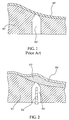
FIG. 1 , if the thickness of the cortical bone (for example, upper gum) 101 in the implant area around thesinus floor 100 is insufficient and must be lifted, the existing method is to make adrill hole 102 in thecortical bone 101 by osteotomy, and then, as shown inFIG. 2 , to separate a part of thesinus floor 100 from thecortical bone 101, and then to fill a bone growth powder/biomedical filler 103 into the crevice between thesinus floor 100 and thecortical bone 101 so as to increase the thickness of thecortical bone 101 and to facilitate the follow-up implant installation procedure. During this bone growth powder/biomedical filler filling procedure, the amount of the applied bone growth powder/biomedical filler is determined subject to the condition of the patient's dental implant bone area. When separating thesinus floor 100 from thecortical bone 101, the dentist must carefully perform the procedure not to pierce the sinus floor, avoiding serious sequelae. - An early bone growth powder/biomedical filler filling tool for dental implant comprises a
push pin 104 at the end of a handle for pushing the applied bone growth powder/biomedical filler 103 from thedrill hole 102 in thecortical bone 101 into the crevice between thecortical bone 101 and thesinus floor 100. However, this bone growth powder/biomedical filler filling tool is not convenient to operate. It takes much time to fill the applied bone growth powder/biomedical filler into the crevice between the cortical bone and the sinus floor with this design of bone growth powder/biomedical filler filling tool. Operating this bone growth powder/biomedical filler filling tool is a big burden to the dentist and can make the patient feel uncomfortable. - Taiwan Patent
M440763 -
EP2578182 discloses a dental implant. - The present invention has been accomplished under the circumstances in view. It is one object of the present invention to provide a sinus implant that simultaneously pushes the applied bone growth powder/biomedical filler into place without damaging or piercing the sinus floor during installation.
- To achieve this and other objects of the present invention, a sinus implant in accordance with the present invention comprises a mounting hole axially defined therein, a plurality of positioning threads spirally upwardly extended around the periphery thereof and gradually reducing in width in direction from a bottom side toward an opposing top side thereof, at least one spiral groove extending around the periphery thereof across the positioning threads, and a pushing tip of reduced diameter located at respective top ends of the positioning threads. The tip comprises a flat end face, and a recess space defined in the flat end face in communication with each spiral groove.
- Preferably, the pushing tip further comprises a smoothly arched outer guide edge extending around the border of the flat end face, and a smoothly arched inner guide edge extending around the recess space within the flat end face.
- Preferably, the recess space is shaped like a hemisphere.
- Further, the positioning threads and each spiral groove can be designed to extend spirally upwardly in the same direction. Alternatively, the positioning threads and each spiral groove can be designed to extend spirally in reversed directions.
-
-
FIG. 1 is a schematic sectional view illustrating a drill hole formed in upper gum by osteotomy. -
FIG. 2 corresponds toFIG. 1 , illustrating a bone growth powder/biomedical filler filled in the crevice between the upper gum and the sinus floor. -
FIG. 3 is an oblique top elevational view of a sinus implant in accordance with a first embodiment of the present invention. -
FIG. 4 is a front view of the sinus implant in accordance with the first embodiment of the present invention. -
FIG. 5 is a longitudinal sectional view of the sinus implant in accordance with the first embodiment of the present invention. -
FIG. 6 is a top view of the sinus implant in accordance with the first embodiment of the present invention. -
FIG. 7 is a schematic applied view of the first embodiment of the present invention, illustrating the installed position of the sinus implant relative to the upper gum and the sinus floor. -
FIG. 8 is an enlarged view of Part A ofFIG. 7 . -
FIG. 9 is a schematic drawing illustrating the action of the installation of the sinus implant of the first embodiment of the present invention in the upper gum. -
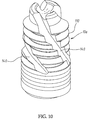
FIG. 10 is an oblique top elevational view of a sinus implant in accordance with a second embodiment of the present invention. -
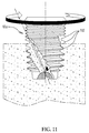
FIG. 11 is a schematic drawing illustrating the action of the installation of the sinus implant of the second embodiment of the present invention in the upper gum. - Referring to
FIGS. 3-6 , asinus implant 10 in accordance with a first embodiment of the present invention is shown. Thesinus implant 10 is prepared from zirconium dioxide, comprising animplant root 13 at a bottom side thereof, amounting hole 12 axially defined therein and upwardly extended from a bottom edge of theimplant root 13 to a predetermined height (seeFIG. 5 ), a plurality ofpositioning threads 11 spirally upwardly extended around the periphery thereof and gradually reducing in width in direction from theimplant root 13 toward an opposing top side thereof to form a gum-drilling structure. In this embodiment, thepositioning threads 11 extend upwardly in clockwise direction at a fixed pitch. However, this thread extending direction is simply an example but not intended to limit the present invention. Alternatively, thepositioning threads 11 can be designed to extend upwardly in counter-clockwise direction. - The
sinus implant 10 further comprises at least one, for example, threespiral grooves 14 upwardly extending around the periphery thereof across thepositioning threads 11 and equally spaced from one another, and a pushingtip 15 of reduced diameter located at the ends of the positioning threads 11 (i.e. at the top side of the sinus implant 10) in axial alignment with themounting hole 12. The pushingtip 15 defines aflat end face 151, and arecess space 152 in theflat end face 151 in communication with thespiral grooves 14. - In order to facilitate pushing and bone pile and delivery in a save manner, the border area of the
flat end face 151 is preferably smoothened. In this embodiment, theflat end face 151 has a smoothly archedouter guide edge 153 around the border thereof, and a smoothly archedinner guide edge 154 in therecess space 152. - Further, in this embodiment, the
recess space 152 is shaped like a hemisphere. However, this hemispherical shape is simply an example. Therecess space 152 can also be made in any other geometrical shape for accommodation a bone growth powder/biomedical filler. - Referring to
FIG. 7 , in anupper gum 20 implant surgery, thesinus implant 10 must be driven into theupper gum 20 to push the sinus floor (mucosa) 22 of thesinus 21 for filling a bone growth powder/biomedical filler. During the implant surgery, the dentist fills a bone growth powder/biomedical filler 30 into the drill hole that was made by osteotomy, and then drives thesinus implant 10 into the drill hole. At this time, the design of thespiral grooves 14 of thesinus implant 10 and the design of therecessed space 152 in theflat end face 151 of the pushingtip 15 enable the applied bone growth powder/biomedical filler 30 to be pushed forwards by thesinus implant 10. As the pushingtip 15 gradually pushes open thesinus floor 22, the bone growth powder/biomedical filler 30 is forced to enter the crevice between thesinus floor 22 and theupper gum 20, and thus, the bone growth powder/biomedical filler filling operation is synchronously done when the installation of thesinus implant 10 is completed (seeFIG. 8 ). - Referring to
FIG. 9 , thespiral grooves 14 and positioningthreads 11 of thesinus implant 10 in accordance with the first embodiment of the present invention extend spirally in the same direction. Therefore, when driving the sinus implant 10 into theupper gum 20, eachspiral groove 14 works as a chip discharging channel for expelling upper gum chips or excessive bone growth powder/biomedical filler. This embodiment is practical for a patient who needs a less amount of bone growth powder/biomedical filler to be filled in the sinus floor. -
FIG. 10 illustrates asinus implant 10a in accordance with a second embodiment of the present invention. This second embodiment is substantially similar to the aforesaid first embodiment with the exception that thespiral grooves 140 andpositioning threads 110 of thesinus implant 10a of this second embodiment extend spirally in reversed directions, i.e., thepositioning threads 110 extend spirally and upwardly in clockwise direction, and thespiral grooves 140 extend spirally and downwardly in counter-clockwise direction. Thus, when driving thesinus implant 10a into the patient's upper gum in clockwise direction, as shown inFIG. 11 , the bone growth powder/biomedical filler and cut chips will be wholly forced by thepositioning threads 110 into the crevice between the sinus floor and the upper gum. Thus, this embodiment is practical for a patient who needs a large amount of bone growth powder/biomedical filler to be filled in the sinus floor. - In conclusion, the invention provides a sinus implant that is not only effective to prevent from piercing the sinus floor in the sinus implant surgery but also capable of synchronously pushing a selected amount of bone growth powder/biomedical filler into the sinus floor when it is driven into position.
Claims (5)
- A sinus implant (10), comprising a mounting hole (12) axially defined therein, a plurality of positioning threads (11) spirally upwardly extended around the periphery thereof and gradually reducing in width in direction from a bottom side toward an opposing top side thereof, at least one spiral groove (14) extending around the periphery thereof across said positioning threads (11), and a pushing tip (15) of reduced diameter located at respective top ends of said positioning threads (11), said pushing tip (15) comprising a flat end face (151), and a recess space (152) defined in said flat end face (151) in communication with each said spiral groove (14).
- The sinus implant (10) as claimed in claim 1, wherein said pushing tip (15) further comprises a smoothly arched outer guide edge (153) extending around the border of said flat end face (151), and a smoothly arched inner guide edge (154) extending around said recess space within said flat end face (151).
- The sinus implant (10) as claimed in claim 1, wherein said recess space (152) is shaped like a hemisphere.
- The sinus implant (10) as claimed in claim 1, wherein said positioning threads (11) and each said spiral groove (14) extend spirally upwardly in the same direction.
- The sinus implant (10a) as claimed in claim 1, wherein said positioning threads (110) and each said spiral groove (140) extend spirally in reversed directions.
Priority Applications (1)
| Application Number | Priority Date | Filing Date | Title |
|---|---|---|---|
| EP14165367.5A EP2937060B1 (en) | 2014-04-22 | 2014-04-22 | Sinus implant |
Applications Claiming Priority (1)
| Application Number | Priority Date | Filing Date | Title |
|---|---|---|---|
| EP14165367.5A EP2937060B1 (en) | 2014-04-22 | 2014-04-22 | Sinus implant |
Publications (2)
| Publication Number | Publication Date |
|---|---|
| EP2937060A1 EP2937060A1 (en) | 2015-10-28 |
| EP2937060B1 true EP2937060B1 (en) | 2016-09-07 |
Family
ID=50549009
Family Applications (1)
| Application Number | Title | Priority Date | Filing Date |
|---|---|---|---|
| EP14165367.5A Active EP2937060B1 (en) | 2014-04-22 | 2014-04-22 | Sinus implant |
Country Status (1)
| Country | Link |
|---|---|
| EP (1) | EP2937060B1 (en) |
Families Citing this family (1)
| Publication number | Priority date | Publication date | Assignee | Title |
|---|---|---|---|---|
| IT202000008326A1 (en) * | 2020-04-20 | 2021-10-20 | Nodrill S R L | DENTAL IMPLANT TO BE IMPLANTED IN THE POSTERIOR SUPERIOR JAW |
Family Cites Families (7)
| Publication number | Priority date | Publication date | Assignee | Title |
|---|---|---|---|---|
| EP1658824A3 (en) * | 2004-11-18 | 2007-01-17 | Johann Ebenberger | Frusto-conical support for use in elevating the sinus membrane for preparing the insertion of a dental implant. |
| US20090258328A1 (en) * | 2006-11-30 | 2009-10-15 | Chun-Leon Chen | 5 in 1 dental implant method and apparatus |
| IL214635A (en) * | 2008-09-29 | 2013-10-31 | Maxillent Ltd | Implants and implant for sinus lift and lateral ridge augmentation |
| FR2975891A1 (en) * | 2011-06-01 | 2012-12-07 | Laurent Philippe Ruben Ohayon | Dental implant for use during maxillary implant surgery to fill maxillary sinus, has upper coronary part remaining above bone surface to prevent cortical residual resorption due to inflammatory reaction risks on level of implant junction |
| EP2578182A1 (en) * | 2011-10-05 | 2013-04-10 | William Y. S. Hung | Dental implant |
| TWM440763U (en) | 2012-05-16 | 2012-11-11 | jun-long Chen | Bone graft filling device for dental implant |
| US8899980B2 (en) * | 2012-06-04 | 2014-12-02 | Star Generation Limited | Bone powder filling tool for dental implant |
-
2014
- 2014-04-22 EP EP14165367.5A patent/EP2937060B1/en active Active
Also Published As
| Publication number | Publication date |
|---|---|
| EP2937060A1 (en) | 2015-10-28 |
Similar Documents
| Publication | Publication Date | Title |
|---|---|---|
| US10188489B2 (en) | Sinus implant | |
| EP2689743B1 (en) | Drill for implant surgery | |
| EP2561825A2 (en) | Fixture for a dental implant and an implant system comprising the same | |
| EP4327766A2 (en) | Subcutaneous delivery tool | |
| US9855119B2 (en) | Dental implant fixture | |
| US8899980B2 (en) | Bone powder filling tool for dental implant | |
| CN102085113A (en) | Bone screw | |
| CN111263621B (en) | Orientation Confirmation Pin and Pilot Drill Kit for Implant Retention | |
| US20130171585A1 (en) | Apparatus for lifting maxillary sinus | |
| KR20190116604A (en) | Drill bits for dental implant surgery | |
| KR20220088642A (en) | Reamer drill for dental implant procedure | |
| EP3253327B1 (en) | Dental implant for implantation facilitation and stabilization | |
| KR101234296B1 (en) | Drill for operating implant | |
| US9757215B2 (en) | Dental sinus lift device for implant rehabilitation | |
| US20150297320A1 (en) | Implant having a bone growth powder/biomedical filler rotary push structure | |
| EP2937060A1 (en) | Sinus implant | |
| KR102308274B1 (en) | Sinus implant | |
| AU2014202174B2 (en) | Sinus implant | |
| CN202589689U (en) | Artificial implant with coarse and fine threads | |
| EP2937061B1 (en) | Implant having a bone growth powder/biomedical filler rotary push structure | |
| CN204364147U (en) | A kind of implantation body implantation drill bit | |
| AU2015221485A1 (en) | Dental implant | |
| CN204133588U (en) | A kind of pedicle of vertebral arch button | |
| KR100929258B1 (en) | Medical Tapping Mechanism | |
| KR20150122353A (en) | Implant having a bone growth powder/biomedical filler rotary push structure |
Legal Events
| Date | Code | Title | Description |
|---|---|---|---|
| PUAI | Public reference made under article 153(3) epc to a published international application that has entered the european phase |
Free format text: ORIGINAL CODE: 0009012 |
|
| 17P | Request for examination filed |
Effective date: 20150423 |
|
| AK | Designated contracting states |
Kind code of ref document: A1 Designated state(s): AL AT BE BG CH CY CZ DE DK EE ES FI FR GB GR HR HU IE IS IT LI LT LU LV MC MK MT NL NO PL PT RO RS SE SI SK SM TR |
|
| AX | Request for extension of the european patent |
Extension state: BA ME |
|
| RIC1 | Information provided on ipc code assigned before grant |
Ipc: A61C 8/00 20060101AFI20160226BHEP |
|
| RIN1 | Information on inventor provided before grant (corrected) |
Inventor name: CHEN, CHUN-LEON |
|
| GRAP | Despatch of communication of intention to grant a patent |
Free format text: ORIGINAL CODE: EPIDOSNIGR1 |
|
| INTG | Intention to grant announced |
Effective date: 20160601 |
|
| GRAS | Grant fee paid |
Free format text: ORIGINAL CODE: EPIDOSNIGR3 |
|
| GRAA | (expected) grant |
Free format text: ORIGINAL CODE: 0009210 |
|
| AK | Designated contracting states |
Kind code of ref document: B1 Designated state(s): AL AT BE BG CH CY CZ DE DK EE ES FI FR GB GR HR HU IE IS IT LI LT LU LV MC MK MT NL NO PL PT RO RS SE SI SK SM TR |
|
| REG | Reference to a national code |
Ref country code: GB Ref legal event code: FG4D |
|
| REG | Reference to a national code |
Ref country code: CH Ref legal event code: EP |
|
| REG | Reference to a national code |
Ref country code: IE Ref legal event code: FG4D |
|
| REG | Reference to a national code |
Ref country code: DE Ref legal event code: R096 Ref document number: 602014003458 Country of ref document: DE |
|
| REG | Reference to a national code |
Ref country code: AT Ref legal event code: REF Ref document number: 826126 Country of ref document: AT Kind code of ref document: T Effective date: 20161015 |
|
| REG | Reference to a national code |
Ref country code: SE Ref legal event code: TRGR |
|
| REG | Reference to a national code |
Ref country code: LT Ref legal event code: MG4D |
|
| REG | Reference to a national code |
Ref country code: NL Ref legal event code: MP Effective date: 20160907 |
|
| REG | Reference to a national code |
Ref country code: NO Ref legal event code: T2 Effective date: 20160907 |
|
| PG25 | Lapsed in a contracting state [announced via postgrant information from national office to epo] |
Ref country code: HR Free format text: LAPSE BECAUSE OF FAILURE TO SUBMIT A TRANSLATION OF THE DESCRIPTION OR TO PAY THE FEE WITHIN THE PRESCRIBED TIME-LIMIT Effective date: 20160907 Ref country code: FI Free format text: LAPSE BECAUSE OF FAILURE TO SUBMIT A TRANSLATION OF THE DESCRIPTION OR TO PAY THE FEE WITHIN THE PRESCRIBED TIME-LIMIT Effective date: 20160907 Ref country code: RS Free format text: LAPSE BECAUSE OF FAILURE TO SUBMIT A TRANSLATION OF THE DESCRIPTION OR TO PAY THE FEE WITHIN THE PRESCRIBED TIME-LIMIT Effective date: 20160907 Ref country code: LT Free format text: LAPSE BECAUSE OF FAILURE TO SUBMIT A TRANSLATION OF THE DESCRIPTION OR TO PAY THE FEE WITHIN THE PRESCRIBED TIME-LIMIT Effective date: 20160907 |
|
| REG | Reference to a national code |
Ref country code: AT Ref legal event code: MK05 Ref document number: 826126 Country of ref document: AT Kind code of ref document: T Effective date: 20160907 |
|
| PG25 | Lapsed in a contracting state [announced via postgrant information from national office to epo] |
Ref country code: ES Free format text: LAPSE BECAUSE OF FAILURE TO SUBMIT A TRANSLATION OF THE DESCRIPTION OR TO PAY THE FEE WITHIN THE PRESCRIBED TIME-LIMIT Effective date: 20160907 Ref country code: GR Free format text: LAPSE BECAUSE OF FAILURE TO SUBMIT A TRANSLATION OF THE DESCRIPTION OR TO PAY THE FEE WITHIN THE PRESCRIBED TIME-LIMIT Effective date: 20161208 Ref country code: NL Free format text: LAPSE BECAUSE OF FAILURE TO SUBMIT A TRANSLATION OF THE DESCRIPTION OR TO PAY THE FEE WITHIN THE PRESCRIBED TIME-LIMIT Effective date: 20160907 Ref country code: LV Free format text: LAPSE BECAUSE OF FAILURE TO SUBMIT A TRANSLATION OF THE DESCRIPTION OR TO PAY THE FEE WITHIN THE PRESCRIBED TIME-LIMIT Effective date: 20160907 |
|
| PG25 | Lapsed in a contracting state [announced via postgrant information from national office to epo] |
Ref country code: RO Free format text: LAPSE BECAUSE OF FAILURE TO SUBMIT A TRANSLATION OF THE DESCRIPTION OR TO PAY THE FEE WITHIN THE PRESCRIBED TIME-LIMIT Effective date: 20160907 Ref country code: EE Free format text: LAPSE BECAUSE OF FAILURE TO SUBMIT A TRANSLATION OF THE DESCRIPTION OR TO PAY THE FEE WITHIN THE PRESCRIBED TIME-LIMIT Effective date: 20160907 |
|
| REG | Reference to a national code |
Ref country code: FR Ref legal event code: PLFP Year of fee payment: 4 |
|
| PG25 | Lapsed in a contracting state [announced via postgrant information from national office to epo] |
Ref country code: AT Free format text: LAPSE BECAUSE OF FAILURE TO SUBMIT A TRANSLATION OF THE DESCRIPTION OR TO PAY THE FEE WITHIN THE PRESCRIBED TIME-LIMIT Effective date: 20160907 Ref country code: SK Free format text: LAPSE BECAUSE OF FAILURE TO SUBMIT A TRANSLATION OF THE DESCRIPTION OR TO PAY THE FEE WITHIN THE PRESCRIBED TIME-LIMIT Effective date: 20160907 Ref country code: CZ Free format text: LAPSE BECAUSE OF FAILURE TO SUBMIT A TRANSLATION OF THE DESCRIPTION OR TO PAY THE FEE WITHIN THE PRESCRIBED TIME-LIMIT Effective date: 20160907 Ref country code: BE Free format text: LAPSE BECAUSE OF FAILURE TO SUBMIT A TRANSLATION OF THE DESCRIPTION OR TO PAY THE FEE WITHIN THE PRESCRIBED TIME-LIMIT Effective date: 20160907 Ref country code: IS Free format text: LAPSE BECAUSE OF FAILURE TO SUBMIT A TRANSLATION OF THE DESCRIPTION OR TO PAY THE FEE WITHIN THE PRESCRIBED TIME-LIMIT Effective date: 20170107 Ref country code: SM Free format text: LAPSE BECAUSE OF FAILURE TO SUBMIT A TRANSLATION OF THE DESCRIPTION OR TO PAY THE FEE WITHIN THE PRESCRIBED TIME-LIMIT Effective date: 20160907 Ref country code: BG Free format text: LAPSE BECAUSE OF FAILURE TO SUBMIT A TRANSLATION OF THE DESCRIPTION OR TO PAY THE FEE WITHIN THE PRESCRIBED TIME-LIMIT Effective date: 20161207 Ref country code: PT Free format text: LAPSE BECAUSE OF FAILURE TO SUBMIT A TRANSLATION OF THE DESCRIPTION OR TO PAY THE FEE WITHIN THE PRESCRIBED TIME-LIMIT Effective date: 20170109 Ref country code: PL Free format text: LAPSE BECAUSE OF FAILURE TO SUBMIT A TRANSLATION OF THE DESCRIPTION OR TO PAY THE FEE WITHIN THE PRESCRIBED TIME-LIMIT Effective date: 20160907 |
|
| REG | Reference to a national code |
Ref country code: DE Ref legal event code: R097 Ref document number: 602014003458 Country of ref document: DE |
|
| PG25 | Lapsed in a contracting state [announced via postgrant information from national office to epo] |
Ref country code: IT Free format text: LAPSE BECAUSE OF FAILURE TO SUBMIT A TRANSLATION OF THE DESCRIPTION OR TO PAY THE FEE WITHIN THE PRESCRIBED TIME-LIMIT Effective date: 20160907 |
|
| PLBE | No opposition filed within time limit |
Free format text: ORIGINAL CODE: 0009261 |
|
| STAA | Information on the status of an ep patent application or granted ep patent |
Free format text: STATUS: NO OPPOSITION FILED WITHIN TIME LIMIT |
|
| PG25 | Lapsed in a contracting state [announced via postgrant information from national office to epo] |
Ref country code: DK Free format text: LAPSE BECAUSE OF FAILURE TO SUBMIT A TRANSLATION OF THE DESCRIPTION OR TO PAY THE FEE WITHIN THE PRESCRIBED TIME-LIMIT Effective date: 20160907 |
|
| PGFP | Annual fee paid to national office [announced via postgrant information from national office to epo] |
Ref country code: NO Payment date: 20170504 Year of fee payment: 4 Ref country code: FR Payment date: 20170430 Year of fee payment: 4 |
|
| 26N | No opposition filed |
Effective date: 20170608 |
|
| PG25 | Lapsed in a contracting state [announced via postgrant information from national office to epo] |
Ref country code: SI Free format text: LAPSE BECAUSE OF FAILURE TO SUBMIT A TRANSLATION OF THE DESCRIPTION OR TO PAY THE FEE WITHIN THE PRESCRIBED TIME-LIMIT Effective date: 20160907 |
|
| REG | Reference to a national code |
Ref country code: CH Ref legal event code: PL |
|
| REG | Reference to a national code |
Ref country code: IE Ref legal event code: MM4A |
|
| PG25 | Lapsed in a contracting state [announced via postgrant information from national office to epo] |
Ref country code: MC Free format text: LAPSE BECAUSE OF FAILURE TO SUBMIT A TRANSLATION OF THE DESCRIPTION OR TO PAY THE FEE WITHIN THE PRESCRIBED TIME-LIMIT Effective date: 20160907 |
|
| PG25 | Lapsed in a contracting state [announced via postgrant information from national office to epo] |
Ref country code: LU Free format text: LAPSE BECAUSE OF NON-PAYMENT OF DUE FEES Effective date: 20170422 Ref country code: LI Free format text: LAPSE BECAUSE OF NON-PAYMENT OF DUE FEES Effective date: 20170430 Ref country code: CH Free format text: LAPSE BECAUSE OF NON-PAYMENT OF DUE FEES Effective date: 20170430 |
|
| PG25 | Lapsed in a contracting state [announced via postgrant information from national office to epo] |
Ref country code: IE Free format text: LAPSE BECAUSE OF NON-PAYMENT OF DUE FEES Effective date: 20170422 |
|
| PG25 | Lapsed in a contracting state [announced via postgrant information from national office to epo] |
Ref country code: MT Free format text: LAPSE BECAUSE OF NON-PAYMENT OF DUE FEES Effective date: 20170422 |
|
| PG25 | Lapsed in a contracting state [announced via postgrant information from national office to epo] |
Ref country code: AL Free format text: LAPSE BECAUSE OF FAILURE TO SUBMIT A TRANSLATION OF THE DESCRIPTION OR TO PAY THE FEE WITHIN THE PRESCRIBED TIME-LIMIT Effective date: 20160907 |
|
| REG | Reference to a national code |
Ref country code: DE Ref legal event code: R119 Ref document number: 602014003458 Country of ref document: DE |
|
| REG | Reference to a national code |
Ref country code: NO Ref legal event code: MMEP |
|
| REG | Reference to a national code |
Ref country code: SE Ref legal event code: EUG |
|
| GBPC | Gb: european patent ceased through non-payment of renewal fee |
Effective date: 20180422 |
|
| PG25 | Lapsed in a contracting state [announced via postgrant information from national office to epo] |
Ref country code: DE Free format text: LAPSE BECAUSE OF NON-PAYMENT OF DUE FEES Effective date: 20181101 Ref country code: SE Free format text: LAPSE BECAUSE OF NON-PAYMENT OF DUE FEES Effective date: 20180423 Ref country code: NO Free format text: LAPSE BECAUSE OF NON-PAYMENT OF DUE FEES Effective date: 20180430 |
|
| PG25 | Lapsed in a contracting state [announced via postgrant information from national office to epo] |
Ref country code: GB Free format text: LAPSE BECAUSE OF NON-PAYMENT OF DUE FEES Effective date: 20180422 |
|
| PG25 | Lapsed in a contracting state [announced via postgrant information from national office to epo] |
Ref country code: FR Free format text: LAPSE BECAUSE OF NON-PAYMENT OF DUE FEES Effective date: 20180430 |
|
| PG25 | Lapsed in a contracting state [announced via postgrant information from national office to epo] |
Ref country code: HU Free format text: LAPSE BECAUSE OF FAILURE TO SUBMIT A TRANSLATION OF THE DESCRIPTION OR TO PAY THE FEE WITHIN THE PRESCRIBED TIME-LIMIT; INVALID AB INITIO Effective date: 20140422 |
|
| REG | Reference to a national code |
Ref country code: DE Ref legal event code: R073 Ref document number: 602014003458 Country of ref document: DE |
|
| PG25 | Lapsed in a contracting state [announced via postgrant information from national office to epo] |
Ref country code: CY Free format text: LAPSE BECAUSE OF FAILURE TO SUBMIT A TRANSLATION OF THE DESCRIPTION OR TO PAY THE FEE WITHIN THE PRESCRIBED TIME-LIMIT Effective date: 20160907 |
|
| PG25 | Lapsed in a contracting state [announced via postgrant information from national office to epo] |
Ref country code: MK Free format text: LAPSE BECAUSE OF FAILURE TO SUBMIT A TRANSLATION OF THE DESCRIPTION OR TO PAY THE FEE WITHIN THE PRESCRIBED TIME-LIMIT Effective date: 20160907 |
|
| REG | Reference to a national code |
Ref country code: GB Ref legal event code: S28 Free format text: APPLICATION FILED |
|
| REG | Reference to a national code |
Ref country code: DE Ref legal event code: R074 Ref document number: 602014003458 Country of ref document: DE |
|
| PG25 | Lapsed in a contracting state [announced via postgrant information from national office to epo] |
Ref country code: DE Free format text: LAPSE BECAUSE OF NON-PAYMENT OF DUE FEES Effective date: 20181101 |
|
| PGRI | Patent reinstated in contracting state [announced from national office to epo] |
Ref country code: DE Effective date: 20191203 |
|
| REG | Reference to a national code |
Ref country code: GB Ref legal event code: S28 Free format text: RESTORATION ALLOWED Effective date: 20200130 |
|
| PG25 | Lapsed in a contracting state [announced via postgrant information from national office to epo] |
Ref country code: TR Free format text: LAPSE BECAUSE OF FAILURE TO SUBMIT A TRANSLATION OF THE DESCRIPTION OR TO PAY THE FEE WITHIN THE PRESCRIBED TIME-LIMIT Effective date: 20160907 |
|
| REG | Reference to a national code |
Ref country code: SE Ref legal event code: RE72 Effective date: 20200609 |
|
| PG25 | Lapsed in a contracting state [announced via postgrant information from national office to epo] |
Ref country code: SE Free format text: LAPSE BECAUSE OF NON-PAYMENT OF DUE FEES Effective date: 20180423 |
|
| PGRI | Patent reinstated in contracting state [announced from national office to epo] |
Ref country code: SE Effective date: 20200609 |
|
| PGFP | Annual fee paid to national office [announced via postgrant information from national office to epo] |
Ref country code: SE Payment date: 20260120 Year of fee payment: 13 |
|
| PGFP | Annual fee paid to national office [announced via postgrant information from national office to epo] |
Ref country code: GB Payment date: 20260205 Year of fee payment: 13 |
|
| PGFP | Annual fee paid to national office [announced via postgrant information from national office to epo] |
Ref country code: DE Payment date: 20260123 Year of fee payment: 13 |