EP2937023B1 - Full-automatic tea making device - Google Patents
Full-automatic tea making device Download PDFInfo
- Publication number
- EP2937023B1 EP2937023B1 EP13865825.7A EP13865825A EP2937023B1 EP 2937023 B1 EP2937023 B1 EP 2937023B1 EP 13865825 A EP13865825 A EP 13865825A EP 2937023 B1 EP2937023 B1 EP 2937023B1
- Authority
- EP
- European Patent Office
- Prior art keywords
- tea
- making
- clutch
- full
- assembly
- Prior art date
- Legal status (The legal status is an assumption and is not a legal conclusion. Google has not performed a legal analysis and makes no representation as to the accuracy of the status listed.)
- Active
Links
Images



Classifications
-
- A—HUMAN NECESSITIES
- A47—FURNITURE; DOMESTIC ARTICLES OR APPLIANCES; COFFEE MILLS; SPICE MILLS; SUCTION CLEANERS IN GENERAL
- A47J—KITCHEN EQUIPMENT; COFFEE MILLS; SPICE MILLS; APPARATUS FOR MAKING BEVERAGES
- A47J31/00—Apparatus for making beverages
- A47J31/18—Apparatus in which ground coffee or tea-leaves are immersed in the hot liquid in the beverage container
- A47J31/20—Apparatus in which ground coffee or tea-leaves are immersed in the hot liquid in the beverage container having immersible, e.g. rotatable, filters
Definitions
- the present application relates to a tea-making machine, and more particularly, relates to a full-automatic tea-making machine.
- Drinking tea is a living habit of the Chinese.
- automatic tea-making machines have been manufactured to make it convenient for tea-making.
- a heating assembly is usually arranged in these automatic tea-making machines to boil or heat water.
- hot water is poured into a container with a tea basket, or the tea basket is soaked in the hot water through up-and-down movements thereof. After being soaked for a while, the water and tea leaves are automatically separated from each other.
- the automatic tea-making machines in the prior art have the following defects: when making tea, by pouring the hot water into a container with a tea basket, or making the tea basket soaked in the hot water through up-and-down movements thereof, the tea leaves can not move quickly in the hot water and can not be fully infused.
- Lassota US 8 286 547 B1 teaches a French press-like quality high volume, electrical, automatic beverage brewer with a rotatable mixing chamber for mixing water from a hot water tank with dry beverage ingredient having a closed top and an open bottom to which is releasably mounted a brew basket with an open top for fluid communication with the mixing chamber through the open bottom.
- a brew basket with an open top for fluid communication with the mixing chamber through the open bottom.
- the present application is to provide a full-automatic tea-making machine configured to automatically wash tea leaves, aiming at the defect of the automatic tea-making machine in the prior art that can not automatically wash tea leaves.
- an automatic tea-making machine comprising a base assembly and a tea-making assembly arranged on the base assembly; wherein a water pump configured to pump water into the tea-making assembly and a motor are arranged on the base assembly; and the tea-making assembly includes:
- the full-automatic tea-making machine further includes a waste water tank assembly arranged below the drain valve.
- the tea basket includes two positions: a first position in which the tea basket rotates in a first direction to press onto the drain valve and further close the drain valve, and a second position in which the tea basket rotates in a second direction to separate from the drain valve.
- the full-automatic tea-making machine further comprises a first clutch and a second clutch cooperated with each other to transmit a power between the motor and the tea basket, wherein the first clutch is driven by the motor, and the second clutch is configured to transmit the power to the tea basket.
- a helicoidal surface is defined on the first clutch; when the motor rotates in a first direction, the first clutch is cooperated with the second clutch at a lowest point of the helicoidal surface; and when the motor rotates in a second direction, the first clutch is cooperated with the second clutch at a lowest point of the helicoidal surface.
- the tea-making assembly further includes a siphon arranged on the base assembly; the siphon includes a siphon inlet pipe communicating with an internal part of the tea-making cavity, and a siphon outlet pipe; and an upper end of the siphon inlet pipe is connected to an upper end of the siphon outlet pipe.
- a recessed receiving part of the tea-making assembly is defined on a top of the base assembly, and the tea-making assembly is received in the receiving part of the tea-making assembly.
- a transmission shaft receiving cylinder is fixed in the receiving part of the tea-making assembly, a transmission shaft is arranged in the transmission shaft receiving cylinder, and an upper end of the transmission shaft extends through the transmission shaft receiving cylinder, and is further connected to the tea basket.
- the full-automatic tea-making machine further includes a water purification chamber and a heating unit arranged on the base assembly; the water pump is connected to the water purification chamber through an inlet pipe and is connected to the heating unit through a first delivery pipe; and the heating unit is connected to the tea-making assembly through a second delivery pipe.
- the full-automatic tea-making machine of the present application the following advantageous effects can be achieved: it can automatically wash tea leaves and make tea and thus it is convenient to use.
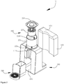
- Fig. 1 is a stereogram of a full-automatic tea-making machine 10 according to the present application.
- Fig. 2 is an exploded schematic view of the full-automatic tea-making machine according to the present application.
- the full-automatic tea-making machine 10 comprises a base assembly 100, a tea-making assembly 200, and a waste water tank assembly 300 arranged on the base assembly 100.
- Fig. 3 is a cutaway view of the full-automatic tea-making machine 10 according to the present application.
- a recessed receiving part 101 for the tea-making assembly is defined on a top of the base assembly 100.
- An opening is further defined on a top of the receiving part 101 for the tea-making assembly, and thus a cylindrical receiving chamber is formed to receive the tea-making assembly 200.
- a receiving recess 102 for the waste water tank assembly is defined on one side of the base assembly 100, and the shape and the size of the receiving recess are corresponding to those of the waste water tank assembly 300, and thus it is possible for the waste water tank assembly 300 to be arranged into the receiving recess.
- a water purification chamber 103 configured to hold clean water is defined on the other side of the base assembly 100.
- an opening is defined on a top of the water purification chamber 103, and a cover 104 of the water purification chamber is further defined in the water purification chamber 103. Users can open the cover 104 of the water purification chamber and add water into the water purification chamber 103.
- An inlet valve 105 is arranged at the bottom of the water purification chamber 103.
- a water pump 106 and a heating unit 107 are further arranged in the base assembly 100.
- the water pump 106 is connected to the inlet valve 105 through an inlet pipe 108 to pump water from the water purification chamber 103.
- the water pump 106 is connected to the heating unit 107 through a first delivery pipe 109, and the heating unit 107 is connected to the tea-making assembly 200 through a second delivery pipe 110.
- winding pipelines are arranged in the heating unit 107 to heat the water that flows therethrough.
- the first delivery pipe 109 is connected to the second delivery pipe 110 after winding through the heating unit 107.
- Fig. 4 is a cutaway view of the full-automatic tea-making machine 10 in another direction according to the present application.
- Fig. 5 is a cutaway view of the full-automatic tea-making machine 10 in a further direction according to the present application.
- a motor 111 and a reduction gearbox 112 are further arranged in the base assembly 100.
- a first clutch 113 is arranged in the reduction gearbox 112 and is driven to rotate by the motor 111.
- a transmission shaft receiving cylinder 114 is fixed in the receiving part 101 for the tea-making assembly of the base assembly 100.
- a transmission shaft 115 is arranged in the transmission shaft receiving cylinder 114.
- a lower end of the transmission shaft 115 is connected to the first clutch 113 through a second clutch 116, and an upper end of the transmission shaft 115 extends through the transmission shaft receiving cylinder 114.
- the second clutch 116 is configured to transmit power to the tea basket 202.
- An opening is defined on the top of the transmission shaft receiving cylinder 114.
- An inlet hole 118 is defined on the bottom of the transmission shaft receiving cylinder 114 and the inlet hole 118 is connected to the second delivery pipe 110.
- a sealing ring 117 is arranged between the transmission shaft 115 and a lower end of the transmission shaft receiving cylinder 114. The sealing ring 117 is arranged below the inlet hole 118.
- the present application is not limited here, and it is also possible for the second delivery pipe 110 to delivery water to the tea-making assembly 200 with other structures.
- the tea-making assembly 200 comprises a tea-making cavity 201, a tea basket 202, and a tea-making cavity cover 204.
- the tea-making cavity 201 is in a cylindric shape with an open top part, a closed bottom part and a closed peripheral wall.
- a hole for the transmission shaft receiving cylinder 114 to pass through is defined at the centre of the bottom of the tea-making cavity 201.
- the tea basket 202 is arranged inside the tea-making cavity 201 and is sheathed outside the transmission shaft receiving cylinder 114.
- the tea basket 202 has a top part, a bottom part and a side wall, wherein a plurality of small holes are defined on the top part 208.
- the side wall of the tea basket 202 is made of porous materials such as gauze, in such a way that it is convenient for the water to enter into the tea basket 202, and for making tea.
- the bottom part of the tea basket 202 is closed, and a fixed cylinder 205 is fixed in the center of the bottom part and extends upward vertically.
- the fixed cylinder 205 is sheathed outside the transmission shaft receiving cylinder 114, and a top of the fixed cylinder 205 is closed.
- An inlet hole 206 communicated with the tea basket 202 is defined on an upper end of the fixed cylinder 205, wherein the inlet hole 206 is located above the upper end of the transmission shaft receiving cylinder 114.
- a sealing element is arranged between the fixed cylinder 205 and the transmission shaft receiving cylinder 114.
- An upper connector 207 is arranged inside the fixed cylinder 205, and the tea basket 202 is fixed to the transmission shaft 115 through the upper connector 207.
- a drain valve 213 is further arranged in the tea-making cavity 201.
- the drain valve 213 is located at the bottom of the tea-making cavity 201 and is communicated with the inner part of the tea-making cavity 201.
- the waste water tank assembly 300 can be directly placed under the drain valve 213 to get water.
- the waste water tank assembly 300 is arranged below the drain valve 213 and is connected to the drain valve 213 through a drain pipe.
- a drain plug 214 is arranged in the drain valve 213 and an upper end of the drain plug 214 extends to the inner part of the tea-making cavity 201.
- An elastic element 215 configured to open the drain plug 214 is arranged in the drain valve 213. An elastic force is constantly applied to the drain plug 214 by the elastic element 215 in such a way that the drain plug 214 is in an opening position.
- a siphon 119 is arranged on the base assembly 100.
- the siphon 119 comprises a siphon outlet pipe 120 and a siphon inlet pipe 121.
- a lower end of the siphon inlet pipe 121 is communicated with the inner part of the tea-making cavity 201, and an upper end of the siphon inlet pipe 121 is communicated with an upper end of the siphon outlet pipe 120.
- a lower end of the siphon outlet pipe 120 extends until it protrudes out of the bottom of the tea-making cavity 201.
- a corresponding recessed part 301 and a placing board 302 extending and protruding out of the recessed part 301 are arranged on the waste water tank assembly 300.
- the recessed part 301 is located under the siphon 119, and containers such as cups can be placed on the placing board 302 to get water.
- containers such as cups can be placed on the placing board 302 to get water.
- the water will enter the siphon 119 through the siphon inlet pipe 121. After the water exceeds the top of the siphon inlet pipe 121, it will further enter the siphon outlet pipe 120 and flow into the containers such as cups, through the siphon outlet pipe 120.
- Fig. 6 is a structural schematic view of the second clutch 116.
- Fig. 7 is a structural schematic view of the first clutch 113.
- a center hole 116a configured to cooperate with the lower end of the transmission shaft 115 by interference fit is defined in the second clutch 116.
- a plurality of helicoidal surfaces 116b and two stop surfaces 116c respectively located at two ends of the helicoidal surface 116b are defined on an outer peripheral surface of the second clutch 116.
- a lowest point A and a highest point B adjacent to the stop surface 116c are defined on each helicoidal surface 116b.
- a connecting ring 113a configured for the second clutch 116 to insert into is defined on the first clutch 113, and a plurality of columns 113b are defined on an inner surface of the connecting ring 113a.
- a controller is further arranged on the base assembly 100, and is configured to control the on-and-off state of the heating unit 107, and further control a running time of the motor 111 during which the motor 111 runs in a first direction or a second direction.
- the working principle of the full-automatic tea-making machine 10 will be described as follows: when making tea, water is added into the water purification chamber 103, and the tea-making cavity cover 204 is opened to add tea leaves into the tea basket 202. After that, the full-automatic tea-making machine 10 is started, the inlet valve 105 at the bottom of the water purification chamber 103 is opened; and the water pump 106 and the heating unit 107 begin to work. The water later passes through the inlet pipe 108 and the first delivery pipe 109, and then arrives at the heating unit 107 and is heated to a preset temperature. Then the water passes through the second delivery pipe 110 and enters the tea-making assembly 200.
- the motor 111 is energized and rotates in the first direction.
- a torque is transmitted to the first clutch 113 through the reduction gearbox 112.
- Top ends of the plurality of columns 113b of the first clutch 113 are abutted against the highest point B of the corresponding helicoidal surfaces 116b of the second clutch 116.
- the sidewalls of the columns 113b of the first clutch 113 are abutted against the stop surfaces 116c to drive the transmission shaft 115 to rotate.
- the tea basket 202 is driven to rotate by the transmission shaft 115 through the upper end connector 207, and the tea leaves therein are stirred and fully washed, in this way, the tea washing is achieved.
- the motor 111 rotates in the first direction
- the tea basket 202 is put in a first position and is pressed on the drain plug 214, and the drain valve 213 is closed under the gravity of the tea basket 202.
- the motor 111 When the motor 111 has rotated in the first direction for a preset period, the tea leaves in the tea basket 210 has been washed thoroughly.
- the motor 111 rotates in the second direction opposite to the first direction under the control of the controller, and the top ends of the plurality of columns 113b of the first clutch 113 are abutted against the lowest point A of the corresponding helicoidal surfaces 116b of the second clutch 116. Since the position of the first clutch 113 is fixed, the second clutch 116 will be jacked up and move upwards, meanwhile the transmission shaft 115 is driven to move upwards and the tea basket 202 is driven to move upwards by the transmission shaft 115.
- the tea basket 202 is lifted to a second position separated from the drain valve 213.
- the drain valve 213 is opened so that the water configured to wash tea leaves will pass through the drain valve 213 and enter the waste water tank assembly 300.
- the motor 111 rotates in the second direction for a preset period, the water configured to wash tea leaves has been completely discharged.
- the motor 111 rotates in the first direction under the control of the controller, and the above processes will be repeated to make tea.
- the water in the tea-making assembly 200 exceeds the top end of the siphon inlet pipe 121 of the siphon 119, it will enter the siphon inlet pipe 121 and pass through the siphon outlet pipe 120, and finally flow into the containers such as cups.
- a plurality of helicoidal surfaces 116b are defined on the outer peripheral surface of the second clutch 116, however, the present application is not limited here.
- a plurality of helicoidal surfaces can be defined on the first clutch, and the columns may be arranged on the second clutch.
- the full-automatic tea-making machine of the present application can automatically wash tea and make tea, and it is very convenient to use.
Landscapes
- Engineering & Computer Science (AREA)
- Food Science & Technology (AREA)
- Apparatus For Making Beverages (AREA)
Description
- The present application relates to a tea-making machine, and more particularly, relates to a full-automatic tea-making machine.
- Drinking tea is a living habit of the Chinese. Currently, in the market, automatic tea-making machines have been manufactured to make it convenient for tea-making. A heating assembly is usually arranged in these automatic tea-making machines to boil or heat water. When making tea, hot water is poured into a container with a tea basket, or the tea basket is soaked in the hot water through up-and-down movements thereof. After being soaked for a while, the water and tea leaves are automatically separated from each other.
- The automatic tea-making machines in the prior art have the following defects: when making tea, by pouring the hot water into a container with a tea basket, or making the tea basket soaked in the hot water through up-and-down movements thereof, the tea leaves can not move quickly in the hot water and can not be fully infused.
- In addition, dust, impurity, pesticide, noxious bacteria or the like are often covered on tea leaves, thus when making tea, the tea leaves need to be washed by hot water firstly. In the prior art, no automatic tea-making machine can automatically wash the tea leaves.
- Lassota (
US 8 286 547 B1 ) teaches a French press-like quality high volume, electrical, automatic beverage brewer with a rotatable mixing chamber for mixing
water from a hot water tank with dry beverage ingredient having a closed top and an open bottom to which is releasably mounted a brew basket with an open top for fluid communication with the mixing chamber through the open bottom. However, when operating the water pumping of such automatic beverage brewer is not very effective and placidly, which may affecting the tea-making. - The present application is to provide a full-automatic tea-making machine configured to automatically wash tea leaves, aiming at the defect of the automatic tea-making machine in the prior art that can not automatically wash tea leaves.
- The technical solutions of the present application for solving the technical problems are as follows: an automatic tea-making machine is provided, which comprising a base assembly and a tea-making assembly arranged on the base assembly;
wherein a water pump configured to pump water into the tea-making assembly and a motor are arranged on the base assembly; and
the tea-making assembly includes: - a tea-making cavity with an open top part, a closed bottom part and a closed peripheral wall;
- a tea basket driven by the motor; and
- a drain valve arranged at the bottom of the tea-making cavity and communicated with the tea-making cavity.
- Preferably, the full-automatic tea-making machine further includes a waste water tank assembly arranged below the drain valve.
- Preferably, the tea basket includes two positions: a first position in which the tea basket rotates in a first direction to press onto the drain valve and further close the drain valve, and a second position in which the tea basket rotates in a second direction to separate from the drain valve.
- According to the invention, the full-automatic tea-making machine further comprises a first clutch and a second clutch cooperated with each other to transmit a power between the motor and the tea basket, wherein the first clutch is driven by the motor, and the second clutch is configured to transmit the power to the tea basket.
- Preferably, a helicoidal surface is defined on the first clutch; when the motor rotates in a first direction, the first clutch is cooperated with the second clutch at a lowest point of the helicoidal surface; and when the motor rotates in a second direction, the first clutch is cooperated with the second clutch at a lowest point of the helicoidal surface.
- Preferably, the tea-making assembly further includes a siphon arranged on the base assembly; the siphon includes a siphon inlet pipe communicating with an internal part of the tea-making cavity, and a siphon outlet pipe; and an upper end of the siphon inlet pipe is connected to an upper end of the siphon outlet pipe. Preferably, a recessed receiving part of the tea-making assembly is defined on a top of the base assembly, and the tea-making assembly is received in the receiving part of the tea-making assembly.
- Preferably, a transmission shaft receiving cylinder is fixed in the receiving part of the tea-making assembly, a transmission shaft is arranged in the transmission shaft receiving cylinder, and an upper end of the transmission shaft extends through the transmission shaft receiving cylinder, and is further connected to the tea basket.
- Preferably, the full-automatic tea-making machine further includes a water purification chamber and a heating unit arranged on the base assembly; the water pump is connected to the water purification chamber through an inlet pipe and is connected to the heating unit through a first delivery pipe; and the heating unit is connected to the tea-making assembly through a second delivery pipe. When implementing the full-automatic tea-making machine of the present application, the following advantageous effects can be achieved: it can automatically wash tea leaves and make tea and thus it is convenient to use.
- The present application will be further described with reference to the accompanying drawings and embodiments in the following, in the accompanying drawings:
-
Fig. 1 is a stereogram of a full-automatic tea-making machine according to the present application; -
Fig. 2 is an exploded schematic view of the full-automatic tea-making machine according to the present application; -
Fig. 3 is a cutaway view of the full-automatic tea-making machine according to the present application; -
Fig. 4 is a cutaway view of the full-automatic tea-making machine in another direction according to the present application; -
Fig. 5 is a cutaway view of a full-automatic tea-making machine in a further direction, according to the present application; -
Fig. 6 is a structural schematic view of a second clutch; and -
Fig. 7 is a structural schematic view of a first clutch. - To make the objective, the technical solution and the advantages of the present application to be understood more clearly, now the present application is described in detail. It should be understood that, the specific embodiment described here is only for explanation, not for limitation.
-
Fig. 1 is a stereogram of a full-automatic tea-makingmachine 10 according to the present application.Fig. 2 is an exploded schematic view of the full-automatic tea-making machine according to the present application. As shown inFig. 1 andFig. 2 , the full-automatic tea-making machine 10 comprises abase assembly 100, a tea-making assembly 200, and a wastewater tank assembly 300 arranged on thebase assembly 100. -
Fig. 3 is a cutaway view of the full-automatic tea-makingmachine 10 according to the present application. Combing withFig. 1 to Fig. 3 , in the shown embodiments, a recessed receivingpart 101 for the tea-making assembly is defined on a top of thebase assembly 100. An opening is further defined on a top of thereceiving part 101 for the tea-making assembly, and thus a cylindrical receiving chamber is formed to receive the tea-making assembly 200. Areceiving recess 102 for the waste water tank assembly is defined on one side of thebase assembly 100, and the shape and the size of the receiving recess are corresponding to those of the wastewater tank assembly 300, and thus it is possible for the wastewater tank assembly 300 to be arranged into the receiving recess. - A
water purification chamber 103 configured to hold clean water is defined on the other side of thebase assembly 100. In this case, an opening is defined on a top of thewater purification chamber 103, and acover 104 of the water purification chamber is further defined in thewater purification chamber 103. Users can open thecover 104 of the water purification chamber and add water into thewater purification chamber 103. Aninlet valve 105 is arranged at the bottom of thewater purification chamber 103. - A
water pump 106 and aheating unit 107 are further arranged in thebase assembly 100. Thewater pump 106 is connected to theinlet valve 105 through aninlet pipe 108 to pump water from thewater purification chamber 103. Meanwhile, thewater pump 106 is connected to theheating unit 107 through afirst delivery pipe 109, and theheating unit 107 is connected to the tea-making assembly 200 through asecond delivery pipe 110. In an embodiment of the present application, winding pipelines are arranged in theheating unit 107 to heat the water that flows therethrough. In another embodiment of the present application, thefirst delivery pipe 109 is connected to thesecond delivery pipe 110 after winding through theheating unit 107. When thewater pump 106 is working, water is pumped from thewater purification chamber 103, and is introduced into the tea-making assembly 200 after being heated by theheating unit 107. -
Fig. 4 is a cutaway view of the full-automatic tea-makingmachine 10 in another direction according to the present application.Fig. 5 is a cutaway view of the full-automatic tea-makingmachine 10 in a further direction according to the present application. As shown inFigs. 2 ,4 and5 , amotor 111 and areduction gearbox 112 are further arranged in thebase assembly 100. Afirst clutch 113 is arranged in thereduction gearbox 112 and is driven to rotate by themotor 111. A transmissionshaft receiving cylinder 114 is fixed in thereceiving part 101 for the tea-making assembly of thebase assembly 100. Atransmission shaft 115 is arranged in the transmissionshaft receiving cylinder 114. A lower end of thetransmission shaft 115 is connected to the first clutch 113 through asecond clutch 116, and an upper end of thetransmission shaft 115 extends through the transmissionshaft receiving cylinder 114. Thesecond clutch 116 is configured to transmit power to thetea basket 202. - An opening is defined on the top of the transmission
shaft receiving cylinder 114. Aninlet hole 118 is defined on the bottom of the transmissionshaft receiving cylinder 114 and theinlet hole 118 is connected to thesecond delivery pipe 110. A sealingring 117 is arranged between thetransmission shaft 115 and a lower end of the transmissionshaft receiving cylinder 114. The sealingring 117 is arranged below theinlet hole 118. However, the present application is not limited here, and it is also possible for thesecond delivery pipe 110 to delivery water to the tea-makingassembly 200 with other structures. - The tea-making
assembly 200 comprises a tea-makingcavity 201, atea basket 202, and a tea-makingcavity cover 204. The tea-makingcavity 201 is in a cylindric shape with an open top part, a closed bottom part and a closed peripheral wall. A hole for the transmissionshaft receiving cylinder 114 to pass through is defined at the centre of the bottom of the tea-makingcavity 201. Thetea basket 202 is arranged inside the tea-makingcavity 201 and is sheathed outside the transmissionshaft receiving cylinder 114. Thetea basket 202 has a top part, a bottom part and a side wall, wherein a plurality of small holes are defined on the top part 208. The side wall of thetea basket 202 is made of porous materials such as gauze, in such a way that it is convenient for the water to enter into thetea basket 202, and for making tea. Specifically, the bottom part of thetea basket 202 is closed, and afixed cylinder 205 is fixed in the center of the bottom part and extends upward vertically. In this case, the fixedcylinder 205 is sheathed outside the transmissionshaft receiving cylinder 114, and a top of the fixedcylinder 205 is closed. An inlet hole 206 communicated with thetea basket 202 is defined on an upper end of the fixedcylinder 205, wherein the inlet hole 206 is located above the upper end of the transmissionshaft receiving cylinder 114. A sealing element is arranged between thefixed cylinder 205 and the transmissionshaft receiving cylinder 114. - An
upper connector 207 is arranged inside the fixedcylinder 205, and thetea basket 202 is fixed to thetransmission shaft 115 through theupper connector 207. - A
drain valve 213 is further arranged in the tea-makingcavity 201. In this case, thedrain valve 213 is located at the bottom of the tea-makingcavity 201 and is communicated with the inner part of the tea-makingcavity 201. In the shown embodiment, the wastewater tank assembly 300 can be directly placed under thedrain valve 213 to get water. In other embodiments of the present application, the wastewater tank assembly 300 is arranged below thedrain valve 213 and is connected to thedrain valve 213 through a drain pipe. - A
drain plug 214 is arranged in thedrain valve 213 and an upper end of thedrain plug 214 extends to the inner part of the tea-makingcavity 201. Anelastic element 215 configured to open thedrain plug 214 is arranged in thedrain valve 213. An elastic force is constantly applied to thedrain plug 214 by theelastic element 215 in such a way that thedrain plug 214 is in an opening position. - A siphon 119 is arranged on the
base assembly 100. In this case, the siphon 119 comprises a siphonoutlet pipe 120 and a siphoninlet pipe 121. A lower end of the siphoninlet pipe 121 is communicated with the inner part of the tea-makingcavity 201, and an upper end of the siphoninlet pipe 121 is communicated with an upper end of the siphonoutlet pipe 120. A lower end of the siphonoutlet pipe 120 extends until it protrudes out of the bottom of the tea-makingcavity 201. A corresponding recessedpart 301 and a placingboard 302 extending and protruding out of the recessedpart 301 are arranged on the wastewater tank assembly 300. The recessedpart 301 is located under the siphon 119, and containers such as cups can be placed on the placingboard 302 to get water. When there is too much water in the tea-makingcavity 201, the water will enter the siphon 119 through the siphoninlet pipe 121. After the water exceeds the top of the siphoninlet pipe 121, it will further enter the siphonoutlet pipe 120 and flow into the containers such as cups, through the siphonoutlet pipe 120. -
Fig. 6 is a structural schematic view of thesecond clutch 116.Fig. 7 is a structural schematic view of thefirst clutch 113. As shown inFig. 6 , acenter hole 116a configured to cooperate with the lower end of thetransmission shaft 115 by interference fit is defined in thesecond clutch 116. A plurality ofhelicoidal surfaces 116b and two stopsurfaces 116c respectively located at two ends of thehelicoidal surface 116b are defined on an outer peripheral surface of thesecond clutch 116. A lowest point A and a highest point B adjacent to thestop surface 116c are defined on eachhelicoidal surface 116b. Now referring toFig. 7 , a connectingring 113a configured for thesecond clutch 116 to insert into is defined on thefirst clutch 113, and a plurality ofcolumns 113b are defined on an inner surface of the connectingring 113a. When thesecond clutch 116 is inserted into the connectingring 113a on thefirst clutch 113, thecolumns 113b will be respectively abutted against the correspondinghelicoidal surfaces 116b. - A controller is further arranged on the
base assembly 100, and is configured to control the on-and-off state of theheating unit 107, and further control a running time of themotor 111 during which themotor 111 runs in a first direction or a second direction. - The working principle of the full-automatic tea-making
machine 10 will be described as follows: when making tea, water is added into thewater purification chamber 103, and the tea-makingcavity cover 204 is opened to add tea leaves into thetea basket 202. After that, the full-automatic tea-makingmachine 10 is started, theinlet valve 105 at the bottom of thewater purification chamber 103 is opened; and thewater pump 106 and theheating unit 107 begin to work. The water later passes through theinlet pipe 108 and thefirst delivery pipe 109, and then arrives at theheating unit 107 and is heated to a preset temperature. Then the water passes through thesecond delivery pipe 110 and enters the tea-makingassembly 200. - Meanwhile, the
motor 111 is energized and rotates in the first direction. A torque is transmitted to the first clutch 113 through thereduction gearbox 112. Top ends of the plurality ofcolumns 113b of thefirst clutch 113 are abutted against the highest point B of the correspondinghelicoidal surfaces 116b of thesecond clutch 116. The sidewalls of thecolumns 113b of thefirst clutch 113 are abutted against the stop surfaces 116c to drive thetransmission shaft 115 to rotate. Thetea basket 202 is driven to rotate by thetransmission shaft 115 through theupper end connector 207, and the tea leaves therein are stirred and fully washed, in this way, the tea washing is achieved. When themotor 111 rotates in the first direction, thetea basket 202 is put in a first position and is pressed on thedrain plug 214, and thedrain valve 213 is closed under the gravity of thetea basket 202. - When the
motor 111 has rotated in the first direction for a preset period, the tea leaves in the tea basket 210 has been washed thoroughly. Themotor 111 rotates in the second direction opposite to the first direction under the control of the controller, and the top ends of the plurality ofcolumns 113b of thefirst clutch 113 are abutted against the lowest point A of the correspondinghelicoidal surfaces 116b of thesecond clutch 116. Since the position of thefirst clutch 113 is fixed, thesecond clutch 116 will be jacked up and move upwards, meanwhile thetransmission shaft 115 is driven to move upwards and thetea basket 202 is driven to move upwards by thetransmission shaft 115. Thetea basket 202 is lifted to a second position separated from thedrain valve 213. Thedrain valve 213 is opened so that the water configured to wash tea leaves will pass through thedrain valve 213 and enter the wastewater tank assembly 300. - When the
motor 111 rotates in the second direction for a preset period, the water configured to wash tea leaves has been completely discharged. Themotor 111 rotates in the first direction under the control of the controller, and the above processes will be repeated to make tea. After the water in the tea-makingassembly 200 exceeds the top end of the siphoninlet pipe 121 of the siphon 119, it will enter the siphoninlet pipe 121 and pass through the siphonoutlet pipe 120, and finally flow into the containers such as cups. - The above embodiment describes the situation that a plurality of
helicoidal surfaces 116b are defined on the outer peripheral surface of thesecond clutch 116, however, the present application is not limited here. In another embodiment, a plurality of helicoidal surfaces can be defined on the first clutch, and the columns may be arranged on the second clutch. When the motor rotates in the first direction, the first clutch cooperates with the second clutch at the lowest point of the helicoidal surface. When the motor rotates in the second direction, the first clutch cooperates with the second clutch at the highest point of the helicoidal surface. - Comparing with the prior art, the full-automatic tea-making machine of the present application can automatically wash tea and make tea, and it is very convenient to use.
- While the embodiments of the present application are described with reference to the accompanying drawings above, the present application is not limited to the above-mentioned specific implementations. In the inspiration of the present application, those ordinary skills in the art can also make many modifications, equivalent replacements or improvements without breaking away from the subject of the present application and the protection scope of the claims. All those belong to the protection of the present application.
Claims (9)
- A full-automatic tea-making machine, comprising a base assembly (100) and a tea-making assembly (200) arranged on the base assembly (100), wherein,
a water pump (106) configured to pump water into the tea-making assembly (200) and a motor (111) are arranged on the base assembly (100);
the tea-making assembly (200) includes:a tea-making cavity (201) with an open top part, a closed bottom part and a closed peripheral wall;a tea basket (202) driven by the motor (111); anda drain valve (213) arranged at the bottom of the tea-making cavity (201) and communicated with the tea-making cavity (201);characterised in that the full-automatic tea-making machine further comprises a first clutch (113) and a second clutch (116) cooperated with each other to transmit a power between the motor (111) and the tea basket (202), wherein the first clutch (113) is driven by the motor (111), and the second clutch (116) is configured to transmit the power to the tea basket (202). - The full-automatic tea-making machine according to claim 1, characterised in that the full-automatic tea-making machine further includes a waste water tank assembly (300) arranged below the drain valve (213).
- The full-automatic tea-making machine according to claim 1, characterised in that the tea basket (202) includes two positions: a first position in which the tea basket (202) rotates in a first direction to press onto the drain valve (213) and further close the drain valve (213), and a second position in which the tea basket (202) rotates in a second direction to separate from the drain valve (213).
- The full-automatic tea-making machine according to claim 1, characterised in that a helicoidal surface (116b) is defined on the first clutch (113);
when the motor (111) rotates in a first direction, the first clutch (113) is cooperated with the second clutch (116) at a lowest point (A) of the helicoidal surface (116b); and
when the motor (111) rotates in a second direction, the first clutch (113) is cooperated with the second clutch (116) at a highest point (B) of the helicoidal surface (116b). - The full-automatic tea-making machine according to claim 1, characterised in that a helicoidal surface (116b) is defined on the second clutch (116);
when the motor (111) rotates in a first direction, the first clutch (113) is cooperated with the second clutch (116) at a highest point (B) of the helicoidal surface (116b); and
when the motor (111) rotates in a second direction, the first clutch (113) is cooperated with the second clutch (116) at a lowest point (A) of the helicoidal surface (116b). - The full-automatic tea-making machine according to claim 1, characterised in that the tea-making assembly (200) further includes a siphon (119) arranged on the base assembly (100); the siphon (119) includes a siphon inlet pipe (121) communicating with an internal part of the tea-making cavity (201), and a siphon outlet pipe (120); and an upper end of the siphon inlet pipe (121) is connected to an upper end of the siphon outlet pipe (120).
- The full-automatic tea-making machine according to claim 1, characterised in that a recessed receiving part (101) of the tea-making assembly (200) is defined on a top of the base assembly (100), and the tea-making assembly (200) is received in the receiving part (101) of the tea-making assembly (200).
- The full-automatic tea-making machine according to claim 7, characterised in that a transmission shaft receiving cylinder (114) is fixed in the receiving part (101) of the tea-making assembly (200), a transmission shaft (115) is arranged in the transmission shaft receiving cylinder (114), and an upper end of the transmission shaft (115) extends through the transmission shaft receiving cylinder (114), and is further connected to the tea basket (202).
- The full-automatic tea-making machine according to claim 1, characterised in that the full-automatic tea-making machine further includes a water purification chamber (103) and a heating unit (107) arranged on the base assembly (100);
the water pump (106) is connected to the water purification chamber (103) through an inlet pipe and is connected to the heating unit (107) through a first delivery pipe; and
the heating unit (107) is connected to the tea-making assembly (200) through a second delivery pipe.
Applications Claiming Priority (3)
| Application Number | Priority Date | Filing Date | Title |
|---|---|---|---|
| CN201210551617.3A CN103860022B (en) | 2012-12-18 | 2012-12-18 | Full-automatic tea maker |
| CN201310334511.2A CN104337317B (en) | 2013-08-02 | 2013-08-02 | automatic tea maker |
| PCT/CN2013/082852 WO2014094457A1 (en) | 2012-12-18 | 2013-09-03 | Full-automatic tea making device |
Publications (3)
| Publication Number | Publication Date |
|---|---|
| EP2937023A1 EP2937023A1 (en) | 2015-10-28 |
| EP2937023A4 EP2937023A4 (en) | 2017-03-08 |
| EP2937023B1 true EP2937023B1 (en) | 2018-08-08 |
Family
ID=50977593
Family Applications (1)
| Application Number | Title | Priority Date | Filing Date |
|---|---|---|---|
| EP13865825.7A Active EP2937023B1 (en) | 2012-12-18 | 2013-09-03 | Full-automatic tea making device |
Country Status (4)
| Country | Link |
|---|---|
| US (1) | US9808115B2 (en) |
| EP (1) | EP2937023B1 (en) |
| AU (1) | AU2013362622B2 (en) |
| WO (1) | WO2014094457A1 (en) |
Families Citing this family (3)
| Publication number | Priority date | Publication date | Assignee | Title |
|---|---|---|---|---|
| JP6506722B2 (en) * | 2016-05-16 | 2019-04-24 | 象印マホービン株式会社 | Tea beverage production device |
| CN106419568A (en) * | 2016-11-30 | 2017-02-22 | 河北工业大学 | Remotely-controlled automatic tea-making machine |
| FR3125402B1 (en) | 2021-07-22 | 2023-07-14 | Alban Stamm | Device for preparing a hot or cold drink by infusing a product in water |
Family Cites Families (18)
| Publication number | Priority date | Publication date | Assignee | Title |
|---|---|---|---|---|
| EP0280794A1 (en) | 1987-03-03 | 1988-09-07 | Animo B.V. | Process and apparatus for brewing hot beverages |
| CN2225202Y (en) | 1995-06-28 | 1996-04-24 | 蔡志民 | Water outlet device using siphon principle |
| JP3942756B2 (en) * | 1998-12-08 | 2007-07-11 | 日本電産サンキョー株式会社 | Small pump device and electric kettle pot |
| US7717026B1 (en) * | 2003-05-28 | 2010-05-18 | Food Equipment Technologies Company, Inc. | Multicontrolled brewer for optimum flavor extraction |
| JP2005287642A (en) | 2004-03-31 | 2005-10-20 | Tiger Vacuum Bottle Co Ltd | Electric kettle with tea function |
| CN1593310A (en) | 2004-07-12 | 2005-03-16 | 李文庆 | Automatic tea soaking machine |
| EP1855571A2 (en) * | 2005-02-28 | 2007-11-21 | Coffee Nation Ltd. | Apparatus for preparing beverages |
| CN201005519Y (en) * | 2007-01-05 | 2008-01-16 | 宁波贝仕迪电器有限公司 | Coffee bag fixing device of the coffee-making machine |
| EP1994866A1 (en) * | 2007-05-23 | 2008-11-26 | Rhea Vendors S.p.A. | Device for grinding coffee or other alimentary substances |
| BRPI0909236A8 (en) * | 2008-03-24 | 2019-02-12 | Bunn O Matic Corp | fermenter system with active fermentation mechanism and fermentation damper reservoir piston compression |
| US9668496B1 (en) * | 2008-05-23 | 2017-06-06 | Food Equipment Technoloigies Company, Inc. | Method of brewing a beverage with an electric, automatic beverage maker |
| CN100584255C (en) | 2008-07-04 | 2010-01-27 | 唐仲湖 | automatic tea table |
| CN201227172Y (en) | 2008-07-04 | 2009-04-29 | 唐仲湖 | Full-automatic tea making table |
| US8459178B2 (en) * | 2008-12-19 | 2013-06-11 | Harold F Miller | Tea brewing and dispensing system and method |
| CH700288A2 (en) | 2009-01-28 | 2010-07-30 | Semeuse Marc A Bloch | Automatic hot beverage preparing machine i.e. coffee machine, has discharge device used for unlocking and opening extraction chamber, swinging pivoting support and ejecting used portion into recovery tray immediately after extraction |
| WO2010093642A1 (en) * | 2009-02-12 | 2010-08-19 | William Fishbein | Beverage brewing process and system |
| CN201422582Y (en) | 2009-06-06 | 2010-03-17 | 吴炳权 | Novel tea table |
| EP2371247B1 (en) * | 2010-03-29 | 2012-12-05 | Schaerer AG | Brewing device for a coffee machine |
-
2013
- 2013-09-03 EP EP13865825.7A patent/EP2937023B1/en active Active
- 2013-09-03 US US14/653,837 patent/US9808115B2/en active Active
- 2013-09-03 AU AU2013362622A patent/AU2013362622B2/en active Active
- 2013-09-03 WO PCT/CN2013/082852 patent/WO2014094457A1/en not_active Ceased
Non-Patent Citations (1)
| Title |
|---|
| None * |
Also Published As
| Publication number | Publication date |
|---|---|
| US9808115B2 (en) | 2017-11-07 |
| WO2014094457A1 (en) | 2014-06-26 |
| US20150327716A1 (en) | 2015-11-19 |
| EP2937023A1 (en) | 2015-10-28 |
| AU2013362622A1 (en) | 2015-07-02 |
| AU2013362622B2 (en) | 2016-11-24 |
| EP2937023A4 (en) | 2017-03-08 |
Similar Documents
| Publication | Publication Date | Title |
|---|---|---|
| CN109998392B (en) | a food processor | |
| EP3252202B1 (en) | Reduction clutch capable of positioning inner drum and washing machine | |
| CN101301166A (en) | Full-automatic tea making table | |
| US9808115B2 (en) | Full-automatic tea-making machine | |
| CN104337317B (en) | automatic tea maker | |
| CN113969487A (en) | Washing apparatus and control method thereof | |
| CN202698862U (en) | Stirring device of coffee machine and coffee machine | |
| CN203280249U (en) | Automatic tea-making machine | |
| CN107536476B (en) | Rice washing device and rice washing electric rice cooker | |
| CN213605860U (en) | Tea set | |
| CN106691192B (en) | Automatic beverage brewing equipment | |
| WO2025077777A1 (en) | Siphon type tea maker | |
| EP1901638B1 (en) | Coffee maschine structure with high flexibility of use | |
| CN206659678U (en) | Switch type filter | |
| CN103860022B (en) | Full-automatic tea maker | |
| CN111938387A (en) | Multifunctional teapot | |
| CN214595519U (en) | A fully automatic tea making device | |
| CN204318456U (en) | A kind of leak through type coffee machine | |
| CN210124614U (en) | Overflow liquid self-cleaning mechanism of coffee machine | |
| KR100538650B1 (en) | Combines Coffee-maker and Water Machine | |
| CN213155426U (en) | Beverage brewing device | |
| CN223929941U (en) | Electric thermos bottle | |
| CN221980559U (en) | A water discharge structure and tea drinking machine | |
| CN210471900U (en) | Tea boiling machine | |
| CN215653909U (en) | Tea extraction component and tea extraction device |
Legal Events
| Date | Code | Title | Description |
|---|---|---|---|
| PUAI | Public reference made under article 153(3) epc to a published international application that has entered the european phase |
Free format text: ORIGINAL CODE: 0009012 |
|
| 17P | Request for examination filed |
Effective date: 20150617 |
|
| AK | Designated contracting states |
Kind code of ref document: A1 Designated state(s): AL AT BE BG CH CY CZ DE DK EE ES FI FR GB GR HR HU IE IS IT LI LT LU LV MC MK MT NL NO PL PT RO RS SE SI SK SM TR |
|
| AX | Request for extension of the european patent |
Extension state: BA ME |
|
| RAP1 | Party data changed (applicant data changed or rights of an application transferred) |
Owner name: MAIN POWER ELECTRICAL FACTORY LTD. |
|
| DAX | Request for extension of the european patent (deleted) | ||
| A4 | Supplementary search report drawn up and despatched |
Effective date: 20170208 |
|
| RIC1 | Information provided on ipc code assigned before grant |
Ipc: A47G 19/16 20060101AFI20170202BHEP Ipc: A47J 31/20 20060101ALI20170202BHEP |
|
| GRAP | Despatch of communication of intention to grant a patent |
Free format text: ORIGINAL CODE: EPIDOSNIGR1 |
|
| STAA | Information on the status of an ep patent application or granted ep patent |
Free format text: STATUS: GRANT OF PATENT IS INTENDED |
|
| RAP1 | Party data changed (applicant data changed or rights of an application transferred) |
Owner name: MAIN POWER INNOTECH (SHENZHEN) MANUFACTURING CO. L |
|
| INTG | Intention to grant announced |
Effective date: 20180412 |
|
| GRAS | Grant fee paid |
Free format text: ORIGINAL CODE: EPIDOSNIGR3 |
|
| GRAA | (expected) grant |
Free format text: ORIGINAL CODE: 0009210 |
|
| STAA | Information on the status of an ep patent application or granted ep patent |
Free format text: STATUS: THE PATENT HAS BEEN GRANTED |
|
| AK | Designated contracting states |
Kind code of ref document: B1 Designated state(s): AL AT BE BG CH CY CZ DE DK EE ES FI FR GB GR HR HU IE IS IT LI LT LU LV MC MK MT NL NO PL PT RO RS SE SI SK SM TR |
|
| REG | Reference to a national code |
Ref country code: GB Ref legal event code: FG4D |
|
| REG | Reference to a national code |
Ref country code: CH Ref legal event code: EP Ref country code: AT Ref legal event code: REF Ref document number: 1026006 Country of ref document: AT Kind code of ref document: T Effective date: 20180815 |
|
| REG | Reference to a national code |
Ref country code: IE Ref legal event code: FG4D |
|
| REG | Reference to a national code |
Ref country code: DE Ref legal event code: R096 Ref document number: 602013041850 Country of ref document: DE |
|
| REG | Reference to a national code |
Ref country code: FR Ref legal event code: PLFP Year of fee payment: 6 |
|
| REG | Reference to a national code |
Ref country code: NL Ref legal event code: MP Effective date: 20180808 |
|
| REG | Reference to a national code |
Ref country code: LT Ref legal event code: MG4D |
|
| REG | Reference to a national code |
Ref country code: AT Ref legal event code: MK05 Ref document number: 1026006 Country of ref document: AT Kind code of ref document: T Effective date: 20180808 |
|
| PG25 | Lapsed in a contracting state [announced via postgrant information from national office to epo] |
Ref country code: GR Free format text: LAPSE BECAUSE OF FAILURE TO SUBMIT A TRANSLATION OF THE DESCRIPTION OR TO PAY THE FEE WITHIN THE PRESCRIBED TIME-LIMIT Effective date: 20181109 Ref country code: BG Free format text: LAPSE BECAUSE OF FAILURE TO SUBMIT A TRANSLATION OF THE DESCRIPTION OR TO PAY THE FEE WITHIN THE PRESCRIBED TIME-LIMIT Effective date: 20181108 Ref country code: NO Free format text: LAPSE BECAUSE OF FAILURE TO SUBMIT A TRANSLATION OF THE DESCRIPTION OR TO PAY THE FEE WITHIN THE PRESCRIBED TIME-LIMIT Effective date: 20181108 Ref country code: AT Free format text: LAPSE BECAUSE OF FAILURE TO SUBMIT A TRANSLATION OF THE DESCRIPTION OR TO PAY THE FEE WITHIN THE PRESCRIBED TIME-LIMIT Effective date: 20180808 Ref country code: PL Free format text: LAPSE BECAUSE OF FAILURE TO SUBMIT A TRANSLATION OF THE DESCRIPTION OR TO PAY THE FEE WITHIN THE PRESCRIBED TIME-LIMIT Effective date: 20180808 Ref country code: IS Free format text: LAPSE BECAUSE OF FAILURE TO SUBMIT A TRANSLATION OF THE DESCRIPTION OR TO PAY THE FEE WITHIN THE PRESCRIBED TIME-LIMIT Effective date: 20181208 Ref country code: NL Free format text: LAPSE BECAUSE OF FAILURE TO SUBMIT A TRANSLATION OF THE DESCRIPTION OR TO PAY THE FEE WITHIN THE PRESCRIBED TIME-LIMIT Effective date: 20180808 Ref country code: RS Free format text: LAPSE BECAUSE OF FAILURE TO SUBMIT A TRANSLATION OF THE DESCRIPTION OR TO PAY THE FEE WITHIN THE PRESCRIBED TIME-LIMIT Effective date: 20180808 Ref country code: FI Free format text: LAPSE BECAUSE OF FAILURE TO SUBMIT A TRANSLATION OF THE DESCRIPTION OR TO PAY THE FEE WITHIN THE PRESCRIBED TIME-LIMIT Effective date: 20180808 Ref country code: LT Free format text: LAPSE BECAUSE OF FAILURE TO SUBMIT A TRANSLATION OF THE DESCRIPTION OR TO PAY THE FEE WITHIN THE PRESCRIBED TIME-LIMIT Effective date: 20180808 Ref country code: SE Free format text: LAPSE BECAUSE OF FAILURE TO SUBMIT A TRANSLATION OF THE DESCRIPTION OR TO PAY THE FEE WITHIN THE PRESCRIBED TIME-LIMIT Effective date: 20180808 |
|
| PG25 | Lapsed in a contracting state [announced via postgrant information from national office to epo] |
Ref country code: AL Free format text: LAPSE BECAUSE OF FAILURE TO SUBMIT A TRANSLATION OF THE DESCRIPTION OR TO PAY THE FEE WITHIN THE PRESCRIBED TIME-LIMIT Effective date: 20180808 Ref country code: HR Free format text: LAPSE BECAUSE OF FAILURE TO SUBMIT A TRANSLATION OF THE DESCRIPTION OR TO PAY THE FEE WITHIN THE PRESCRIBED TIME-LIMIT Effective date: 20180808 Ref country code: LV Free format text: LAPSE BECAUSE OF FAILURE TO SUBMIT A TRANSLATION OF THE DESCRIPTION OR TO PAY THE FEE WITHIN THE PRESCRIBED TIME-LIMIT Effective date: 20180808 |
|
| PG25 | Lapsed in a contracting state [announced via postgrant information from national office to epo] |
Ref country code: ES Free format text: LAPSE BECAUSE OF FAILURE TO SUBMIT A TRANSLATION OF THE DESCRIPTION OR TO PAY THE FEE WITHIN THE PRESCRIBED TIME-LIMIT Effective date: 20180808 Ref country code: RO Free format text: LAPSE BECAUSE OF FAILURE TO SUBMIT A TRANSLATION OF THE DESCRIPTION OR TO PAY THE FEE WITHIN THE PRESCRIBED TIME-LIMIT Effective date: 20180808 Ref country code: IT Free format text: LAPSE BECAUSE OF FAILURE TO SUBMIT A TRANSLATION OF THE DESCRIPTION OR TO PAY THE FEE WITHIN THE PRESCRIBED TIME-LIMIT Effective date: 20180808 Ref country code: CZ Free format text: LAPSE BECAUSE OF FAILURE TO SUBMIT A TRANSLATION OF THE DESCRIPTION OR TO PAY THE FEE WITHIN THE PRESCRIBED TIME-LIMIT Effective date: 20180808 Ref country code: EE Free format text: LAPSE BECAUSE OF FAILURE TO SUBMIT A TRANSLATION OF THE DESCRIPTION OR TO PAY THE FEE WITHIN THE PRESCRIBED TIME-LIMIT Effective date: 20180808 |
|
| REG | Reference to a national code |
Ref country code: CH Ref legal event code: PL |
|
| REG | Reference to a national code |
Ref country code: DE Ref legal event code: R082 Ref document number: 602013041850 Country of ref document: DE Representative=s name: RGTH RICHTER GERBAULET THIELEMANN HOFMANN PATE, DE Ref country code: DE Ref legal event code: R097 Ref document number: 602013041850 Country of ref document: DE |
|
| PG25 | Lapsed in a contracting state [announced via postgrant information from national office to epo] |
Ref country code: SM Free format text: LAPSE BECAUSE OF FAILURE TO SUBMIT A TRANSLATION OF THE DESCRIPTION OR TO PAY THE FEE WITHIN THE PRESCRIBED TIME-LIMIT Effective date: 20180808 Ref country code: DK Free format text: LAPSE BECAUSE OF FAILURE TO SUBMIT A TRANSLATION OF THE DESCRIPTION OR TO PAY THE FEE WITHIN THE PRESCRIBED TIME-LIMIT Effective date: 20180808 Ref country code: SK Free format text: LAPSE BECAUSE OF FAILURE TO SUBMIT A TRANSLATION OF THE DESCRIPTION OR TO PAY THE FEE WITHIN THE PRESCRIBED TIME-LIMIT Effective date: 20180808 |
|
| REG | Reference to a national code |
Ref country code: BE Ref legal event code: MM Effective date: 20180930 |
|
| PLBE | No opposition filed within time limit |
Free format text: ORIGINAL CODE: 0009261 |
|
| STAA | Information on the status of an ep patent application or granted ep patent |
Free format text: STATUS: NO OPPOSITION FILED WITHIN TIME LIMIT |
|
| REG | Reference to a national code |
Ref country code: IE Ref legal event code: MM4A |
|
| PG25 | Lapsed in a contracting state [announced via postgrant information from national office to epo] |
Ref country code: LU Free format text: LAPSE BECAUSE OF NON-PAYMENT OF DUE FEES Effective date: 20180903 Ref country code: MC Free format text: LAPSE BECAUSE OF FAILURE TO SUBMIT A TRANSLATION OF THE DESCRIPTION OR TO PAY THE FEE WITHIN THE PRESCRIBED TIME-LIMIT Effective date: 20180808 |
|
| 26N | No opposition filed |
Effective date: 20190509 |
|
| PG25 | Lapsed in a contracting state [announced via postgrant information from national office to epo] |
Ref country code: IE Free format text: LAPSE BECAUSE OF NON-PAYMENT OF DUE FEES Effective date: 20180903 |
|
| PG25 | Lapsed in a contracting state [announced via postgrant information from national office to epo] |
Ref country code: SI Free format text: LAPSE BECAUSE OF FAILURE TO SUBMIT A TRANSLATION OF THE DESCRIPTION OR TO PAY THE FEE WITHIN THE PRESCRIBED TIME-LIMIT Effective date: 20180808 Ref country code: LI Free format text: LAPSE BECAUSE OF NON-PAYMENT OF DUE FEES Effective date: 20180930 Ref country code: CH Free format text: LAPSE BECAUSE OF NON-PAYMENT OF DUE FEES Effective date: 20180930 Ref country code: BE Free format text: LAPSE BECAUSE OF NON-PAYMENT OF DUE FEES Effective date: 20180930 |
|
| PG25 | Lapsed in a contracting state [announced via postgrant information from national office to epo] |
Ref country code: MT Free format text: LAPSE BECAUSE OF NON-PAYMENT OF DUE FEES Effective date: 20180903 |
|
| PG25 | Lapsed in a contracting state [announced via postgrant information from national office to epo] |
Ref country code: PT Free format text: LAPSE BECAUSE OF FAILURE TO SUBMIT A TRANSLATION OF THE DESCRIPTION OR TO PAY THE FEE WITHIN THE PRESCRIBED TIME-LIMIT Effective date: 20180808 |
|
| PG25 | Lapsed in a contracting state [announced via postgrant information from national office to epo] |
Ref country code: HU Free format text: LAPSE BECAUSE OF FAILURE TO SUBMIT A TRANSLATION OF THE DESCRIPTION OR TO PAY THE FEE WITHIN THE PRESCRIBED TIME-LIMIT; INVALID AB INITIO Effective date: 20130903 Ref country code: CY Free format text: LAPSE BECAUSE OF FAILURE TO SUBMIT A TRANSLATION OF THE DESCRIPTION OR TO PAY THE FEE WITHIN THE PRESCRIBED TIME-LIMIT Effective date: 20180808 Ref country code: MK Free format text: LAPSE BECAUSE OF NON-PAYMENT OF DUE FEES Effective date: 20180808 |
|
| REG | Reference to a national code |
Ref country code: DE Ref legal event code: R082 Ref document number: 602013041850 Country of ref document: DE Representative=s name: RGTH RICHTER GERBAULET THIELEMANN HOFMANN PATE, DE Ref country code: DE Ref legal event code: R081 Ref document number: 602013041850 Country of ref document: DE Owner name: GUANGDONG MIDEA CONSUMER ELECTRIC MANUFACTURIN, CN Free format text: FORMER OWNER: MAIN POWER INNOTECH (SHENZHEN) MANUFACTURING CO. LTD., SHENZHEN, GUANGDONG, CN |
|
| REG | Reference to a national code |
Ref country code: GB Ref legal event code: 732E Free format text: REGISTERED BETWEEN 20210617 AND 20210623 |
|
| PGFP | Annual fee paid to national office [announced via postgrant information from national office to epo] |
Ref country code: DE Payment date: 20250923 Year of fee payment: 13 |
|
| PGFP | Annual fee paid to national office [announced via postgrant information from national office to epo] |
Ref country code: TR Payment date: 20250901 Year of fee payment: 13 |
|
| PGFP | Annual fee paid to national office [announced via postgrant information from national office to epo] |
Ref country code: GB Payment date: 20250915 Year of fee payment: 13 |
|
| PGFP | Annual fee paid to national office [announced via postgrant information from national office to epo] |
Ref country code: FR Payment date: 20250915 Year of fee payment: 13 |