EP2936845B1 - Providing notifications of call-related services - Google Patents
Providing notifications of call-related services Download PDFInfo
- Publication number
- EP2936845B1 EP2936845B1 EP14707496.7A EP14707496A EP2936845B1 EP 2936845 B1 EP2936845 B1 EP 2936845B1 EP 14707496 A EP14707496 A EP 14707496A EP 2936845 B1 EP2936845 B1 EP 2936845B1
- Authority
- EP
- European Patent Office
- Prior art keywords
- terminal
- end terminal
- call
- user
- network
- Prior art date
- Legal status (The legal status is an assumption and is not a legal conclusion. Google has not performed a legal analysis and makes no representation as to the accuracy of the status listed.)
- Active
Links
- 238000001514 detection method Methods 0.000 claims description 27
- 238000005516 engineering process Methods 0.000 claims description 8
- 230000004044 response Effects 0.000 claims description 5
- 230000007613 environmental effect Effects 0.000 claims description 3
- 238000004590 computer program Methods 0.000 claims 2
- 235000008694 Humulus lupulus Nutrition 0.000 claims 1
- 230000005540 biological transmission Effects 0.000 claims 1
- 230000004807 localization Effects 0.000 claims 1
- 238000000034 method Methods 0.000 description 9
- 238000004891 communication Methods 0.000 description 7
- 230000006870 function Effects 0.000 description 4
- 230000001413 cellular effect Effects 0.000 description 3
- 230000000694 effects Effects 0.000 description 3
- 238000012360 testing method Methods 0.000 description 3
- 238000010586 diagram Methods 0.000 description 2
- 230000003287 optical effect Effects 0.000 description 2
- 238000000060 site-specific infrared dichroism spectroscopy Methods 0.000 description 2
- 230000009471 action Effects 0.000 description 1
- 230000003213 activating effect Effects 0.000 description 1
- 230000010267 cellular communication Effects 0.000 description 1
- 230000000295 complement effect Effects 0.000 description 1
- 230000001419 dependent effect Effects 0.000 description 1
- 230000000977 initiatory effect Effects 0.000 description 1
- 238000013507 mapping Methods 0.000 description 1
- 238000010295 mobile communication Methods 0.000 description 1
- 230000008569 process Effects 0.000 description 1
- 238000012545 processing Methods 0.000 description 1
- 238000005070 sampling Methods 0.000 description 1
- 230000011664 signaling Effects 0.000 description 1
- 238000012546 transfer Methods 0.000 description 1
- 230000009466 transformation Effects 0.000 description 1
- 238000010200 validation analysis Methods 0.000 description 1
Images
Classifications
-
- H—ELECTRICITY
- H04—ELECTRIC COMMUNICATION TECHNIQUE
- H04W—WIRELESS COMMUNICATION NETWORKS
- H04W4/00—Services specially adapted for wireless communication networks; Facilities therefor
- H04W4/02—Services making use of location information
-
- H—ELECTRICITY
- H04—ELECTRIC COMMUNICATION TECHNIQUE
- H04M—TELEPHONIC COMMUNICATION
- H04M7/00—Arrangements for interconnection between switching centres
- H04M7/006—Networks other than PSTN/ISDN providing telephone service, e.g. Voice over Internet Protocol (VoIP), including next generation networks with a packet-switched transport layer
- H04M7/0081—Network operation, administration, maintenance, or provisioning
- H04M7/0087—Network planning or provisioning
-
- H—ELECTRICITY
- H04—ELECTRIC COMMUNICATION TECHNIQUE
- H04L—TRANSMISSION OF DIGITAL INFORMATION, e.g. TELEGRAPHIC COMMUNICATION
- H04L65/00—Network arrangements, protocols or services for supporting real-time applications in data packet communication
- H04L65/1066—Session management
- H04L65/1069—Session establishment or de-establishment
-
- H—ELECTRICITY
- H04—ELECTRIC COMMUNICATION TECHNIQUE
- H04L—TRANSMISSION OF DIGITAL INFORMATION, e.g. TELEGRAPHIC COMMUNICATION
- H04L65/00—Network arrangements, protocols or services for supporting real-time applications in data packet communication
- H04L65/80—Responding to QoS
-
- H—ELECTRICITY
- H04—ELECTRIC COMMUNICATION TECHNIQUE
- H04M—TELEPHONIC COMMUNICATION
- H04M1/00—Substation equipment, e.g. for use by subscribers
- H04M1/72—Mobile telephones; Cordless telephones, i.e. devices for establishing wireless links to base stations without route selection
- H04M1/724—User interfaces specially adapted for cordless or mobile telephones
- H04M1/72403—User interfaces specially adapted for cordless or mobile telephones with means for local support of applications that increase the functionality
- H04M1/72409—User interfaces specially adapted for cordless or mobile telephones with means for local support of applications that increase the functionality by interfacing with external accessories
- H04M1/72412—User interfaces specially adapted for cordless or mobile telephones with means for local support of applications that increase the functionality by interfacing with external accessories using two-way short-range wireless interfaces
-
- H—ELECTRICITY
- H04—ELECTRIC COMMUNICATION TECHNIQUE
- H04N—PICTORIAL COMMUNICATION, e.g. TELEVISION
- H04N21/00—Selective content distribution, e.g. interactive television or video on demand [VOD]
- H04N21/40—Client devices specifically adapted for the reception of or interaction with content, e.g. set-top-box [STB]; Operations thereof
- H04N21/47—End-user applications
- H04N21/478—Supplemental services, e.g. displaying phone caller identification, shopping application
- H04N21/4788—Supplemental services, e.g. displaying phone caller identification, shopping application communicating with other users, e.g. chatting
-
- H—ELECTRICITY
- H04—ELECTRIC COMMUNICATION TECHNIQUE
- H04N—PICTORIAL COMMUNICATION, e.g. TELEVISION
- H04N21/00—Selective content distribution, e.g. interactive television or video on demand [VOD]
- H04N21/40—Client devices specifically adapted for the reception of or interaction with content, e.g. set-top-box [STB]; Operations thereof
- H04N21/47—End-user applications
- H04N21/485—End-user interface for client configuration
-
- H—ELECTRICITY
- H04—ELECTRIC COMMUNICATION TECHNIQUE
- H04N—PICTORIAL COMMUNICATION, e.g. TELEVISION
- H04N21/00—Selective content distribution, e.g. interactive television or video on demand [VOD]
- H04N21/40—Client devices specifically adapted for the reception of or interaction with content, e.g. set-top-box [STB]; Operations thereof
- H04N21/47—End-user applications
- H04N21/488—Data services, e.g. news ticker
- H04N21/4882—Data services, e.g. news ticker for displaying messages, e.g. warnings, reminders
-
- H—ELECTRICITY
- H04—ELECTRIC COMMUNICATION TECHNIQUE
- H04N—PICTORIAL COMMUNICATION, e.g. TELEVISION
- H04N7/00—Television systems
- H04N7/14—Systems for two-way working
- H04N7/141—Systems for two-way working between two video terminals, e.g. videophone
- H04N7/147—Communication arrangements, e.g. identifying the communication as a video-communication, intermediate storage of the signals
-
- H—ELECTRICITY
- H04—ELECTRIC COMMUNICATION TECHNIQUE
- H04N—PICTORIAL COMMUNICATION, e.g. TELEVISION
- H04N7/00—Television systems
- H04N7/14—Systems for two-way working
- H04N7/141—Systems for two-way working between two video terminals, e.g. videophone
- H04N7/148—Interfacing a video terminal to a particular transmission medium, e.g. ISDN
-
- H—ELECTRICITY
- H04—ELECTRIC COMMUNICATION TECHNIQUE
- H04W—WIRELESS COMMUNICATION NETWORKS
- H04W64/00—Locating users or terminals or network equipment for network management purposes, e.g. mobility management
-
- H—ELECTRICITY
- H04—ELECTRIC COMMUNICATION TECHNIQUE
- H04W—WIRELESS COMMUNICATION NETWORKS
- H04W76/00—Connection management
- H04W76/10—Connection setup
- H04W76/14—Direct-mode setup
-
- H—ELECTRICITY
- H04—ELECTRIC COMMUNICATION TECHNIQUE
- H04M—TELEPHONIC COMMUNICATION
- H04M1/00—Substation equipment, e.g. for use by subscribers
- H04M1/253—Telephone sets using digital voice transmission
- H04M1/2535—Telephone sets using digital voice transmission adapted for voice communication over an Internet Protocol [IP] network
-
- H—ELECTRICITY
- H04—ELECTRIC COMMUNICATION TECHNIQUE
- H04W—WIRELESS COMMUNICATION NETWORKS
- H04W4/00—Services specially adapted for wireless communication networks; Facilities therefor
- H04W4/02—Services making use of location information
- H04W4/023—Services making use of location information using mutual or relative location information between multiple location based services [LBS] targets or of distance thresholds
-
- H—ELECTRICITY
- H04—ELECTRIC COMMUNICATION TECHNIQUE
- H04W—WIRELESS COMMUNICATION NETWORKS
- H04W4/00—Services specially adapted for wireless communication networks; Facilities therefor
- H04W4/50—Service provisioning or reconfiguring
-
- H—ELECTRICITY
- H04—ELECTRIC COMMUNICATION TECHNIQUE
- H04W—WIRELESS COMMUNICATION NETWORKS
- H04W4/00—Services specially adapted for wireless communication networks; Facilities therefor
- H04W4/80—Services using short range communication, e.g. near-field communication [NFC], radio-frequency identification [RFID] or low energy communication
-
- H—ELECTRICITY
- H04—ELECTRIC COMMUNICATION TECHNIQUE
- H04W—WIRELESS COMMUNICATION NETWORKS
- H04W8/00—Network data management
- H04W8/005—Discovery of network devices, e.g. terminals
Definitions
- VoIP voice over IP
- VoIP allows users to make voice or video calls over packet-based networks such as the Internet.
- VoIP voice over IP
- VoIP voice over IP
- desktop or laptop computers but increasingly nowadays the user tends to have a number of devices around the home or office that can potentially be used in VoIP calls or other such packet-based telephony.
- Document WO 2005/057969 A1 discloses an improved method and arrangements for fast constitution of a wireless communication connection between at least two portable devices, wherein preferably one of the portable devices is capable for cellular communications on a cellular network.
- the disclosure herein relates to an apparatus for use in relation to a first near-end terminal, the first near-end terminal being a mobile user terminal such as a mobile phone, tablet or laptop computer, operable to establish voice or video calls with one or more far-end user terminals over a network, e.g. VoIP calls.
- the apparatus may be implemented at the first near-end user terminal, or at an intermediate network element such as a server, or router or access point of a local wireless network.
- the apparatus comprises a detection module, a notification module and a configuration module (which in embodiments may be implemented as portions of code arranged for execution on one or more processors of the apparatus). These are arranged to operate as follows.
- the detection module detects when the first near-end terminal is within a relative proximity of a second near-end terminal which is available to provide a call-related service in relation to one or more of the voice or video calls. For example the detection may be made on the basis that the first and second near-end terminals are both found on the same local network; e.g. same wireless local area network such as a Wi-Fi network, or same wireless ad-hoc network such as a Bluetooth network. Other options for detecting proximity are also possible, as will be discussed in more detail later.
- this may comprise the possibility of using the second near-end terminal as a media end-point for one of the calls established from the first near-end terminal, so that the second near-end terminal plays out or generates at least one audio or video stream of the call while the first terminal controls the call and/or plays out one or more other audio or video streams of the same call.
- the second near-end terminal could comprise another mobile terminal such as a phone, tablet or laptop for use as a remote microphone or camera; or a terminal such as a desktop computer, television, set-top box or stereo or hi-fi unit for use to play out the audio or video of the call.
- the notification module Based on the detection, the notification module outputs a notification to a user of the first near-end terminal, notifying the user of the call-related service.
- the notification may prompt the user as to whether he or she wishes to accept use of the call-related service from the second near-end terminal (e.g. whether he or she would like to have another terminal like a tablet, TV, etc. set for use as a secondary media end-point to play out or generate the voice or video of the call).
- the configuration module is operable to store a configuration setting configuring the first near-end terminal as having the second near-end terminal identified for later provision of the call-related service, i.e.
- the user may be notified when call-related services are available from one or more other nearby terminals, while the configuration module handles the storing of the relevant setting allowing the call-related service to be pre-configured for use whenever the user later wishes to conduct a call, without having to re-configure on each occasion.
- a notification is provided to a device within the proximity of another device.
- the notification may be intended for a particular device, user or type of device.
- the notification may serve to either announce a resource or provide a user defined message (e.g. notes or announcements).
- the notification may be displayed to the user when the second device is detected, or alternatively only when the user performs an action such as initiating or starting a call.
- Embodiments may be carried out as follows: 1) detect that the first device is co-located with a second device - this may be achieved for example by determining that the first and second devices are connected to the same network; and 2) responsive to detecting that the devices are co-located, activating a service to the user and optionally providing a notification to the user that the service is available.
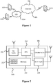
- FIG. 1 gives a schematic example of a communication system in which embodiments disclosed herein may be deployed.
- the system comprises a first near-end device in the form of a first mobile user terminal 102i and a second near-end device in the form of a second user terminal 102ii, which may be a mobile or fixed terminal.
- Each of the user terminals 102 may be any user terminal capable of electronic communications, such as a mobile phone, tablet, laptop or desktop computer, TV set, set-top box, games console, etc.
- the system also comprises a packet-switched network 101 which may take the form of a wide-area inter network such as the Internet, or alternatively a private network.
- the packet-switched network 101 may comprises a sub network 101a, e.g. a wireless local area network (WLAN), comprising wireless network equipment 103 by which the mobile user terminals 102 can access the wireless sub network 101a and the wider network 101.
- the wireless equipment may comprise a wireless access point such as a wi-fi access point (e.g. providing coverage within a café, bar, shop, mall or other retail complex, or railway or bus station, airport or other transport hub); or a wireless router providing coverage in the home (e.g. covering a single home or an apartment block or complex) or office (e.g. covering a single office or company or a plurality of offices or companies within a block or complex).
- a wireless access point such as a wi-fi access point (e.g. providing coverage within a café, bar, shop, mall or other retail complex
- the packet-switched network 101 also comprises other network equipment 105 such as wired switches and routers, and/or other wired or wireless sub networks, via which one or more further, far-end user terminals 102iii may connect to the wider network 101.
- the first (near-end) user terminal 102i is arranged to conduct a voice or video call with one or more such far-end user terminals 102iii over the sub-network 101a (e.g. wireless LAN) and wider packet-based network 101 (e.g. internet).
- sub-network 101a e.g. wireless LAN
- wider packet-based network 101 e.g. internet
- first near-end user terminal 102i is configured to detect presence of one or more second near-end terminals 102ii on the same wireless LAN or other such local or sub network. In this way the first and second near-end terminals may be determined to be approximately co-located, e.g. as they share the same home or office network.
- one or both of the first and second mobile user terminals 102i, 102ii may be equipped with at least one geographic location technology for determining the location of that mobile user terminal, in terms of geographic position relative to the surface of the earth; for example, a satellite based positioning system such as GPS (Global Positioning System, including potential variants such as assisted GPS or differential GPS), GLONASS (Global Navigation Satellite System) or Galileo; and/or trilateration (or more generally muiltilateration) relative to a plurality of different wireless base stations or access points having known locations; and/or a technique based on detecting signal strength relative to a known base station or access point.
- GPS Global Positioning System
- GLONASS Global Navigation Satellite System
- Galileo Galileo
- trilateration or more generally muiltilateration
- one or both of the first and second mobile user terminals 102i, 102ii may be registered with a location service allowing look-up of their geographic position from a server mapping device identifiers (e.g. IP addresses
- At least one of the second near-end terminals 102ii is operable to be involved in the call established by the first near-end user terminal 102i with the far-end terminal 102iii, by providing a call-related service such as acting as a media end-point.
- the first near-end terminal 102i may be a laptop, tablet or desktop computer and the second near-end terminal 102ii may be a mobile phone available to provide the service of providing a remote microphone or camera, to capture a voice or video stream of the call.
- the first near-end terminal 102i may be a mobile phone and the second near-end terminal 102ii may be a tablet, laptop, desktop or TV available to provide the service of playing out a video stream of the call.
- FIG. 2 is a schematic block diagram of a mobile user terminal 102 as might be instantiated by the first user terminal 102i.
- the mobile user terminal 102 comprises a processor 204 in the form of a central processing unit (CPU) comprising one or more cores or execution units, and storage 202 in the form of a memory comprising one or more memory devices comprising one or more storage media (e.g. a magnetic storage medium such as a hard disk or electronic storage such as EEPROM or "flash" memory).
- CPU central processing unit
- storage 202 in the form of a memory comprising one or more memory devices comprising one or more storage media (e.g. a magnetic storage medium such as a hard disk or electronic storage such as EEPROM or "flash" memory).
- storage media e.g. a magnetic storage medium such as a hard disk or electronic storage such as EEPROM or "flash" memory.
- the mobile user terminal 102 also comprises one or more wireless transceivers, in embodiments comprising a cellular transceiver 206 for connecting to the packet-switched network 101 via a mobile cellular network such as a 3GPP network (parts of which may form part of the equipment 105 of the packet-switched network 101), and/or a local wireless transceiver 108 such as a wi-fi transceiver for connecting to the packet switched network 101 via one or more wireless access points 103 of one or more sub networks 101a of the packet-switched network (again at least in part forming some of the equipment of the packet-switched network 101).
- a mobile cellular network such as a 3GPP network (parts of which may form part of the equipment 105 of the packet-switched network 101)
- a local wireless transceiver 108 such as a wi-fi transceiver for connecting to the packet switched network 101 via one or more wireless access points 103 of one or more sub networks 101a of the packet-
- the memory 202 stores computer-readable code arranged to be executed on the processor 204.
- This comprises a VoIP or other communication client application 212 comprising a call engine 213, a detection module 214, a user interface comprising a notification module 215, and a configuration module 216.
- the call engine 213 comprises a call set-up protocol and is thereby arranged to establish VoIP calls (or other packet-based calls) with the far-end terminal 102iii.
- the detection module 214 is arranged to determine whether the first and second near-end terminals 102i, 102ii are within a suitable proximity for provision of one or more call-related services from the second terminal 102ii to the first near-end terminal 102i, and to detect one or more capabilities of the second-near-end terminal 102ii to determine whether the second terminal is operable to provide any such call-related services. In embodiments this is performed by detecting the second near-end terminal on the same local sub-network 101a, e.g. via local transceiver 108.
- the notification module 215 is arranged to provide notifications to the user of the first terminal 102i, e.g.
- the configuration module is arranged to store a configuration setting of the first terminal 102i in a non-volatile storage unit, e.g. in the storage 202 of the first terminal 102i, to thereby set the first near-end user terminal 102i as being configured for using of any detected call-related services.
- the system exploits the fact that at least some portion of the network 101a provides an infrastructure that is fixed, or at least can be assumed to be substantially fixed relative to the first and second terminals 102i, 102ii.
- the first terminal is substantially co-located with a part of the network 101a such as a sub network 101a corresponding to an access point or router 103
- the second terminal 102ii is also known to be co-located with that same sub network 101a
- the sub-network provides a fixed frame of reference
- a user has both a mobile phone 102i and a household or office appliance such as a desktop computer, TV or games console 102i connected to a home router 103.
- the two devices may be able to find each other because they are on the same local network 101a, e.g. same home or office wireless LAN.
- the first device 102i can exploit the fact that the router 103 of sub-network 101a can be assumed to be a fixed reference point for the two devices, and thereby determine that it is substantially co-located with the second device 102ii (e.g. in the same house, apartment or office).
- the second near-end terminal need not comprise a full instance of the communication client 212.
- the complementary application on the second near-end terminal 102ii can be a "stripped down" or "dumb" version of the client that does not comprise call set-up protocol and is not in itself capable of establishing a call with the far-end terminal 102iii, and may in fact have minimal capability.
- the dumb client on the second near-end terminal 102ii may comprise, in the least, a module for performing the relevant call-related service, e.g. playing out audio or video streamed to it over the local network 101a, or providing captured audio or video over the local network 101a; and for communicating its presence and available service(s) on the local network 101a.
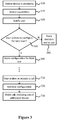
- Figure 3 shows a schematic flow chart of a method that may be implemented by the client application 212 run on the first terminal 102i.
- the detection module 214 on the first near-end terminal checks whether it can detect any second-near end terminal 102ii within a suitable proximity for providing call related services (more detail for implementing this will be discussed below). If so, the detection module 214 determines an identifier of the second near-end terminal 102ii, e.g. an address identifying it on the local network 101a or the wider network 101. At step S15, the detection module 214 also detects the capabilities of the detected terminal 102ii to determine whether it can provide any suitable call-related services, e.g. whether it can act as remote microphone, or whether it can provide a screen for playing out video of a call.
- this may comprise querying the second near-end terminal 102ii over the local network 101a, or detecting a message advertised by the second near-end terminal 102ii over the local network 101a.
- the detection module 214 is able to discover at least an indication that the second terminal 102ii is nearby, an identifier of that second terminal 102ii (e.g. its address), and an indication of one or more capabilities of the second terminal 102ii (i.e. what service or services it can provide).
- the indication of the capability may comprise or include an indication of what type of device the second terminal 102ii is, e.g. phone, tablet, laptop, TV, games console etc.
- the notification module 215 automatically outputs a notification to the user, e.g. on a screen of the first terminal 102i.
- the notification may indicate the second terminal's identity, type, the service and/or the proximity.
- the notification may comprise a user defined element, defined by a user of the first and/or second near-end terminal 102i, 102ii (e.g. "Hi, this is my device, Dave").
- the notification may be dependent on what type of device the first terminal 102i is, or what type of device the second terminal 102ii is, or on the combination of the types of the first and second terminals 102i, 102ii. E.g.
- the notification that a TV set is available for playing out the video of a call may be more emphatic when the first terminal 102i is a mobile phone (having a small screen) than if it is a tablet or laptop (having a larger screen), or alternatively the notification may only be displayed on condition that the first terminal 102i is a certain type of terminal like a mobile phone and not if it is another type like a tablet or laptop.
- the notification may prompt the user of the first near-end terminal 102i as to whether they wish to accept the offer of the call-related service from the second near-end terminal 102ii.
- the notification module 215 receives the user's selection in response to this prompt and determines whether it is affirmative.
- the configuration module 216 stores the user's selection not to accept the service as a configuration setting in a non-volatile storage unit such as the storage 202 on the first terminal 102i itself. If the user does select to accept the service on the other hand, the configuration module 216 instead stores this selection as a configuration setting in the non-volatile storage.
- the first near-end terminal 102i is thus configured to be able to make use of the call-related service offered by the second near-end terminal 102ii.
- the configuration may be stored indefinitely (e.g.
- the second terminal 102i is a household appliance on a home network and the user then leaves the house and returns later, the setting remains stored to continue to indicate the user's selection if he or she then makes or accepts a call at that later time.
- the configuration setting comprises one or more of:
- step T10 the user decides to conduct a voice or video call (e.g. after going out for the day with his or her first, mobile terminal 102i while the second terminal 102ii remains at home, and then later returning home so the two terminals return to proximity).
- the call engine 213 on the first-near-end terminal 102i establishes the call with the far-end terminal 102iii. "Establishing" here may comprise the user of the first terminal 102i making an outgoing call, or accepting an incoming call.
- the configuration module 216 retrieves the configuration setting, comprising the user's prior selection from the time the second near-end terminal 102ii was originally detected and any of the above additional pieces of data.
- the detection module 214 may perform a check to confirm whether the first-near end terminal 102i is currently in the proximity of the second near-end terminal 120ii, for example to check that the first terminal is back on the local network 101a (e.g. based on the SSID) and/or whether it can see the second terminal 102ii on the local network (e.g. based on its address). However in embodiments, as long as the second terminal 102ii is there, the detection module 214 does not need to go through the process of detecting the second terminal's capabilities again as it already has this information stored in the configuration setting.
- the detection module 214 may also provide the user with another prompt to confirm he or she wants to use the service of the second terminal 102ii on this particular occasion.
- this can be a simplified prompt compared with the first prompt at steps S20-S30, as it can already be assumed the user has already understood the nature of the service and has accepted it for potential use. For example when the first terminal 102i rings upon an incoming call, the user could just be presented with two large buttons, one saying "answer with this phone” and the other saying “answer using TV", or the like; whereas at step S20 the notification would have explained the nature of the decision in more detail.
- the use of the second terminal's service could be completely automatic upon making or answering a call.
- the configuration module may automatically select the use of the service without prompt; or may automatically select it in additional dependence on any condition forming part of the retrieved configuration setting (e.g. only if the call is a video call, etc.).
- the user is not notified at step S20, when the second near-end terminal 102ii is originally detected.
- the configuration module 216 may automatically store the configuration at the time without prompting the user for a selection, and the step of notifying can be performed at step T10, when the user makes or receives a call. In this case the user may be prompted at that point whether he or she wishes to use the service from the second terminal 102ii.
- the first near-end terminal 102i then begins to conduct the call with the far-end user terminal 102iii, using the service of the second near-end terminal 102ii based on the configuration setting retrieved from the non-volatile storage.
- this may comprise the second terminal 102ii being used to play out an audio or video stream of the call.
- this may be achieved by receiving the stream at the first terminal 102i from the far-end terminal 102iii over the wider network 101, and forwarding the stream from the first terminal 102i to the second terminal 102ii over the local network.
- the first terminal 102i could instruct the far-end terminal 102iii to redirect the stream directly to the second terminal 102ii.
- the second terminal 102ii is used to generate (e.g. capture) an audio or video stream of the call. In embodiments this may be achieved by receiving the stream at the first terminal 102i from the second terminal 102ii over the local network 101a, and forwarding the stream from the first terminal 102i to the far-end terminal 102iii over the wider network. Alternatively the first terminal 102i could instruct the second terminal 102ii to redirect the stream directly to the far-end terminal 102ii. Either way, while the second terminal 102ii handles one or more of the streams, the first terminal 102i retains possession of call signalling and/or continues to generate or play out or more other streams of the call.
- the second near-end terminal 102ii comprises an analogue telephone adaptor (ATA)
- the network 101 comprises an analogue telephone network
- the far-end user terminal 102iii is an analogue telephone.
- the ATA is a device which plugs into a more traditional analogue telephone at the near end and connects it to the packet-switched network 101 (typically the Internet).
- the call-related service comprises use of the ATA to render a packet-based call received over the network 101 and transfer it to the first near-end terminal 102i.
- two devices 102i, 102ii share a common external IP address (e.g. public IP, or are on the same private network in the context of IPv6) it may be assumed that they are on the same network. For a consumer this means that they are likely to be co-located geographically.
- a common external IP address e.g. public IP, or are on the same private network in the context of IPv6
- these devices may be considered to have a degree of 'implicit trust' (although to a lesser degree in the case where cloud assistance is required). For example in the case where a home shares a common internet connection it is possible (and increasingly likely) that there might be devices sharing a common network.
- One or more of these tests may also be combined with a shared token (either common user identity, passcode (as with Bluetooth), cryptographic key or other shared element - such shared key being prompted as a result of detection of any of the criteria (A) to (D) above; then it can be assumed that there is a trust relationship.
- a shared token either common user identity, passcode (as with Bluetooth), cryptographic key or other shared element - such shared key being prompted as a result of detection of any of the criteria (A) to (D) above; then it can be assumed that there is a trust relationship.
- the first terminal 102i is arranged to determine its geographic location using a geographic location technology, such as GPS or another satellite based location technology, or such as cell triangulation. The first terminal may then determine whether its geographic location is within an geographic area associated with the second terminal 102ii, for example as follows.
- a geographic location technology such as GPS or another satellite based location technology, or such as cell triangulation. The first terminal may then determine whether its geographic location is within an geographic area associated with the second terminal 102ii, for example as follows.
- devices it is possible for devices to make a determination using environmental data (which could be compared in the cloud, or fingerprints of the environment exchanged between the devices) - an example here would be that both devices sample the sound from their surroundings by sampling the sound the pattern of sound can be compared using peaks and troughs in sound and an accurate time reference to correlate the 'environments' around the devices.
- the second device could introduce a sound into the environment which the first device attempts to detect, or vice versa. If the one device can hear the other, they may be determined to be co-located.
- proximity between a first user terminal and a second terminal may be determined based on sound data common to the first and second terminals, and detected by one or both of the two user terminals - either a sound profile of the environment in which the first and second mobile user terminals are located, or a sound deliberately emitted into the environment by one of the first and second terminals to be detected by the other.
- any one or a combination of the above tests may be applied.
- the tests may be determined for example by the decision module 114 of the first terminal 102i querying the second terminal 102ii, or by querying a network element such as a router, access point or server which has record of the relevant information about the second terminal terminal (e.g. the fact that it connects to the same sub network, and/or its IP address, etc.).
- any or all of the detection module 214, notification module 215 and/or configuration module could be implemented at network element such as a server.
- the server may be arranged to receive information such as the IP addresses of the first and second devices 102i, 102ii or an identifier of the sub-network to which they connect (e.g. an ID of the access point or router 103), and to determine proximity centrally. The determination may then be sent to the first terminal 102i, or the server may also be configured to generate the notification at the server and send that to the first terminal. Further, the configuration setting may be stored at a server, and any determination resulting from those configurations communicated from there to the first terminal 102i.
- any or all of these functions could be implemented at the router or access point 103. Further, the above has been described in terms of software modules 212, 213, 214, 215, 216, but it is not excluded that any of these modules is implemented partially or wholly in dedicated hardware.
- any of the functions described herein can be implemented using software, firmware, hardware (e.g., fixed logic circuitry), or a combination of these implementations.
- the terms “module,” “functionality,” “component” and “logic” as used herein generally represent software, firmware, hardware, or a combination thereof.
- the module, functionality, or logic represents program code that performs specified tasks when executed on a processor (e.g. CPU or CPUs).
- the program code can be stored in one or more computer readable memory devices.
- the user terminals may also include an entity (e.g. software) that causes hardware of the user terminals to perform operations, e.g., processors functional blocks, and so on.
- the user terminals may include a computer-readable medium that may be configured to maintain instructions that cause the user terminals, and more particularly the operating system and associated hardware of the user terminals to perform operations.
- the instructions function to configure the operating system and associated hardware to perform the operations and in this way result in transformation of the operating system and associated hardware to perform functions.
- the instructions may be provided by the computer-readable medium to the user terminals through a variety of different configurations.
- One such configuration of a computer-readable medium is signal bearing medium and thus is configured to transmit the instructions (e.g. as a carrier wave) to the computing device, such as via a network.
- the computer-readable medium may also be configured as a computer-readable storage medium and thus is not a signal bearing medium. Examples of a computer-readable storage medium include a random-access memory (RAM), read-only memory (ROM), an optical disc, flash memory, hard disk memory, and other memory devices that may us magnetic, optical, and other techniques to store instructions and other data.
Description
- VoIP (voice over IP) allows users to make voice or video calls over packet-based networks such as the Internet. Traditionally VoIP (voice over IP) calls have been accessed using desktop or laptop computers, but increasingly nowadays the user tends to have a number of devices around the home or office that can potentially be used in VoIP calls or other such packet-based telephony.
- However, organizing or coordinating the use of these different devices is not necessarily straightforward for the user, or user may not even be aware when different devices are available to provide VoIP services or the like.
- Document
WO 2005/057969 A1 discloses an improved method and arrangements for fast constitution of a wireless communication connection between at least two portable devices, wherein preferably one of the portable devices is capable for cellular communications on a cellular network. - According to one aspect, the disclosure herein relates to an apparatus for use in relation to a first near-end terminal, the first near-end terminal being a mobile user terminal such as a mobile phone, tablet or laptop computer, operable to establish voice or video calls with one or more far-end user terminals over a network, e.g. VoIP calls. In embodiments the apparatus may be implemented at the first near-end user terminal, or at an intermediate network element such as a server, or router or access point of a local wireless network. The apparatus comprises a detection module, a notification module and a configuration module (which in embodiments may be implemented as portions of code arranged for execution on one or more processors of the apparatus). These are arranged to operate as follows.
- The detection module detects when the first near-end terminal is within a relative proximity of a second near-end terminal which is available to provide a call-related service in relation to one or more of the voice or video calls. For example the detection may be made on the basis that the first and second near-end terminals are both found on the same local network; e.g. same wireless local area network such as a Wi-Fi network, or same wireless ad-hoc network such as a Bluetooth network. Other options for detecting proximity are also possible, as will be discussed in more detail later. As for the call-related service, in embodiments for example, this may comprise the possibility of using the second near-end terminal as a media end-point for one of the calls established from the first near-end terminal, so that the second near-end terminal plays out or generates at least one audio or video stream of the call while the first terminal controls the call and/or plays out one or more other audio or video streams of the same call. E.g. the second near-end terminal could comprise another mobile terminal such as a phone, tablet or laptop for use as a remote microphone or camera; or a terminal such as a desktop computer, television, set-top box or stereo or hi-fi unit for use to play out the audio or video of the call.
- Based on the detection, the notification module outputs a notification to a user of the first near-end terminal, notifying the user of the call-related service. In embodiments the notification may prompt the user as to whether he or she wishes to accept use of the call-related service from the second near-end terminal (e.g. whether he or she would like to have another terminal like a tablet, TV, etc. set for use as a secondary media end-point to play out or generate the voice or video of the call). Further, in response to the detection (and assuming any user prompt is accepted), the configuration module is operable to store a configuration setting configuring the first near-end terminal as having the second near-end terminal identified for later provision of the call-related service, i.e. to store the configuration setting in a non-volatile storage medium for use of the service on another occasion. In an example use case, this means the user and his or her first (mobile) terminal can depart from the proximity of the second terminal (e.g. leaving the house when the second terminal is a household appliance like a TV), then return and already have the second terminal pre-configured at the first terminal for use in subsequent calls.
- In this way, the user may be notified when call-related services are available from one or more other nearby terminals, while the configuration module handles the storing of the relevant setting allowing the call-related service to be pre-configured for use whenever the user later wishes to conduct a call, without having to re-configure on each occasion.
- The invention is defined by the subject matter of the independent claims.
- This Summary is provided to introduce a selection of concepts in a simplified form that are further described below in the Detailed Description. This Summary is not intended to identify key features or essential features of the claimed subject matter, nor is it intended to be used to limit the scope of the claimed subject matter. Nor is the claimed subject matter limited to implementations that solve any or all of the disadvantages noted in the Background section.
- For a better understanding of the present disclosure and to show how in embodiments it may be put into effect, reference is made by way of example to the accompanying drawings in which:
-
Figure 1 is a schematic representation of a mobile communication system, -
Figure 2 is a schematic block diagram of a mobile user terminal, and -
Figure 3 is a flow chart schematically illustrating a method of providing notifications. - According to embodiments disclosed herein, a notification is provided to a device within the proximity of another device. The notification may be intended for a particular device, user or type of device. The notification may serve to either announce a resource or provide a user defined message (e.g. notes or announcements). The notification may be displayed to the user when the second device is detected, or alternatively only when the user performs an action such as initiating or starting a call.
- Embodiments may be carried out as follows: 1) detect that the first device is co-located with a second device - this may be achieved for example by determining that the first and second devices are connected to the same network; and 2) responsive to detecting that the devices are co-located, activating a service to the user and optionally providing a notification to the user that the service is available.
- The teachings disclosed herein may be implemented in a number of scenarios, for example:
- I) a mobile computing and/or communication device (e.g. phone) may be offered access to a service provided by a TV or games console, such as an offer of consuming the larger, more appropriate screen to render incoming video;
- II) a mobile computing device might offer its local/mobile services such as audio capture to a fixed device (e.g. to use the mobile device as a remote microphone); or
- III) an anchor device such as an ATA (analogue telephone adaptor) might offer access to a locally available service (such as incoming phone calls rendered at the ATA).
-
Figure 1 gives a schematic example of a communication system in which embodiments disclosed herein may be deployed. The system comprises a first near-end device in the form of a firstmobile user terminal 102i and a second near-end device in the form of a second user terminal 102ii, which may be a mobile or fixed terminal. Each of the user terminals 102 may be any user terminal capable of electronic communications, such as a mobile phone, tablet, laptop or desktop computer, TV set, set-top box, games console, etc. - The system also comprises a packet-switched
network 101 which may take the form of a wide-area inter network such as the Internet, or alternatively a private network. The packet-switchednetwork 101 may comprises asub network 101a, e.g. a wireless local area network (WLAN), comprisingwireless network equipment 103 by which the mobile user terminals 102 can access thewireless sub network 101a and thewider network 101. For example the wireless equipment may comprise a wireless access point such as a wi-fi access point (e.g. providing coverage within a café, bar, shop, mall or other retail complex, or railway or bus station, airport or other transport hub); or a wireless router providing coverage in the home (e.g. covering a single home or an apartment block or complex) or office (e.g. covering a single office or company or a plurality of offices or companies within a block or complex). - The packet-switched
network 101 also comprisesother network equipment 105 such as wired switches and routers, and/or other wired or wireless sub networks, via which one or more further, far-end user terminals 102iii may connect to thewider network 101. The first (near-end)user terminal 102i is arranged to conduct a voice or video call with one or more such far-end user terminals 102iii over thesub-network 101a (e.g. wireless LAN) and wider packet-based network 101 (e.g. internet). - Further, the first near-
end user terminal 102i is configured to detect presence of one or more second near-end terminals 102ii on the same wireless LAN or other such local or sub network. In this way the first and second near-end terminals may be determined to be approximately co-located, e.g. as they share the same home or office network. - In some alternative or additional embodiments, one or both of the first and second
mobile user terminals 102i, 102ii may be equipped with at least one geographic location technology for determining the location of that mobile user terminal, in terms of geographic position relative to the surface of the earth; for example, a satellite based positioning system such as GPS (Global Positioning System, including potential variants such as assisted GPS or differential GPS), GLONASS (Global Navigation Satellite System) or Galileo; and/or trilateration (or more generally muiltilateration) relative to a plurality of different wireless base stations or access points having known locations; and/or a technique based on detecting signal strength relative to a known base station or access point. In another example, one or both of the first and secondmobile user terminals 102i, 102ii may be registered with a location service allowing look-up of their geographic position from a server mapping device identifiers (e.g. IP addresses) to locations. - At least one of the second near-end terminals 102ii is operable to be involved in the call established by the first near-
end user terminal 102i with the far-end terminal 102iii, by providing a call-related service such as acting as a media end-point. In some example use cases, the first near-end terminal 102i may be a laptop, tablet or desktop computer and the second near-end terminal 102ii may be a mobile phone available to provide the service of providing a remote microphone or camera, to capture a voice or video stream of the call. In another example, the first near-end terminal 102i may be a mobile phone and the second near-end terminal 102ii may be a tablet, laptop, desktop or TV available to provide the service of playing out a video stream of the call. -
Figure 2 is a schematic block diagram of a mobile user terminal 102 as might be instantiated by thefirst user terminal 102i. The mobile user terminal 102 comprises aprocessor 204 in the form of a central processing unit (CPU) comprising one or more cores or execution units, andstorage 202 in the form of a memory comprising one or more memory devices comprising one or more storage media (e.g. a magnetic storage medium such as a hard disk or electronic storage such as EEPROM or "flash" memory). The mobile user terminal 102 also comprises one or more wireless transceivers, in embodiments comprising acellular transceiver 206 for connecting to the packet-switchednetwork 101 via a mobile cellular network such as a 3GPP network (parts of which may form part of theequipment 105 of the packet-switched network 101), and/or a local wireless transceiver 108 such as a wi-fi transceiver for connecting to the packet switchednetwork 101 via one or morewireless access points 103 of one ormore sub networks 101a of the packet-switched network (again at least in part forming some of the equipment of the packet-switched network 101). - The
memory 202 stores computer-readable code arranged to be executed on theprocessor 204. This comprises a VoIP or othercommunication client application 212 comprising acall engine 213, adetection module 214, a user interface comprising anotification module 215, and aconfiguration module 216. Thecall engine 213 comprises a call set-up protocol and is thereby arranged to establish VoIP calls (or other packet-based calls) with the far-end terminal 102iii. Thedetection module 214 is arranged to determine whether the first and second near-end terminals 102i, 102ii are within a suitable proximity for provision of one or more call-related services from the second terminal 102ii to the first near-end terminal 102i, and to detect one or more capabilities of the second-near-end terminal 102ii to determine whether the second terminal is operable to provide any such call-related services. In embodiments this is performed by detecting the second near-end terminal on the samelocal sub-network 101a, e.g. via local transceiver 108. Thenotification module 215 is arranged to provide notifications to the user of thefirst terminal 102i, e.g. displayed on a screen of thefirst terminal 102i, if proximity of one or more call-related services from one or more other terminals is detected by thedetection module 214. The configuration module is arranged to store a configuration setting of thefirst terminal 102i in a non-volatile storage unit, e.g. in thestorage 202 of thefirst terminal 102i, to thereby set the first near-end user terminal 102i as being configured for using of any detected call-related services. - In order to determine whether the first and second near-
end terminals 102i, 102ii are suitably co-located, it is possible to exploit knowledge of the network to which both theterminals 102i, 102ii are connected. That is, the system exploits the fact that at least some portion of thenetwork 101a provides an infrastructure that is fixed, or at least can be assumed to be substantially fixed relative to the first andsecond terminals 102i, 102ii. For example if it is known that the first terminal is substantially co-located with a part of thenetwork 101a such as asub network 101a corresponding to an access point orrouter 103, and the second terminal 102ii is also known to be co-located with thatsame sub network 101a, and it is assumed that the sub-network provides a fixed frame of reference, then it can be determined appropriate to consider the first terminal andsecond terminals 102i, 102ii effectively co-located. - In an example use case, a user has both a
mobile phone 102i and a household or office appliance such as a desktop computer, TV orgames console 102i connected to ahome router 103. The two devices may be able to find each other because they are on the samelocal network 101a, e.g. same home or office wireless LAN. Further, thefirst device 102i can exploit the fact that therouter 103 of sub-network 101a can be assumed to be a fixed reference point for the two devices, and thereby determine that it is substantially co-located with the second device 102ii (e.g. in the same house, apartment or office). - Note that in embodiments, the second near-end terminal need not comprise a full instance of the
communication client 212. The complementary application on the second near-end terminal 102ii can be a "stripped down" or "dumb" version of the client that does not comprise call set-up protocol and is not in itself capable of establishing a call with the far-end terminal 102iii, and may in fact have minimal capability. Instead, the dumb client on the second near-end terminal 102ii may comprise, in the least, a module for performing the relevant call-related service, e.g. playing out audio or video streamed to it over thelocal network 101a, or providing captured audio or video over thelocal network 101a; and for communicating its presence and available service(s) on thelocal network 101a. -
Figure 3 shows a schematic flow chart of a method that may be implemented by theclient application 212 run on thefirst terminal 102i. - At Step S10, the
detection module 214 on the first near-end terminal checks whether it can detect any second-near end terminal 102ii within a suitable proximity for providing call related services (more detail for implementing this will be discussed below). If so, thedetection module 214 determines an identifier of the second near-end terminal 102ii, e.g. an address identifying it on thelocal network 101a or thewider network 101. At step S15, thedetection module 214 also detects the capabilities of the detected terminal 102ii to determine whether it can provide any suitable call-related services, e.g. whether it can act as remote microphone, or whether it can provide a screen for playing out video of a call. For example this may comprise querying the second near-end terminal 102ii over thelocal network 101a, or detecting a message advertised by the second near-end terminal 102ii over thelocal network 101a. Thus according to step S10 and S15, thedetection module 214 is able to discover at least an indication that the second terminal 102ii is nearby, an identifier of that second terminal 102ii (e.g. its address), and an indication of one or more capabilities of the second terminal 102ii (i.e. what service or services it can provide). The indication of the capability may comprise or include an indication of what type of device the second terminal 102ii is, e.g. phone, tablet, laptop, TV, games console etc. - At step S20, if one such service from a second near-end terminal was detected, the
notification module 215 automatically outputs a notification to the user, e.g. on a screen of thefirst terminal 102i. The notification may indicate the second terminal's identity, type, the service and/or the proximity. In some embodiments the notification may comprise a user defined element, defined by a user of the first and/or second near-end terminal 102i, 102ii (e.g. "Hi, this is my device, Dave"). In some further embodiments the notification may be dependent on what type of device thefirst terminal 102i is, or what type of device the second terminal 102ii is, or on the combination of the types of the first andsecond terminals 102i, 102ii. E.g. the notification that a TV set is available for playing out the video of a call may be more emphatic when thefirst terminal 102i is a mobile phone (having a small screen) than if it is a tablet or laptop (having a larger screen), or alternatively the notification may only be displayed on condition that thefirst terminal 102i is a certain type of terminal like a mobile phone and not if it is another type like a tablet or laptop. - Further, the notification may prompt the user of the first near-
end terminal 102i as to whether they wish to accept the offer of the call-related service from the second near-end terminal 102ii. At step S30 thenotification module 215 receives the user's selection in response to this prompt and determines whether it is affirmative. - If not, at step S40 the
configuration module 216 stores the user's selection not to accept the service as a configuration setting in a non-volatile storage unit such as thestorage 202 on thefirst terminal 102i itself. If the user does select to accept the service on the other hand, theconfiguration module 216 instead stores this selection as a configuration setting in the non-volatile storage. The first near-end terminal 102i is thus configured to be able to make use of the call-related service offered by the second near-end terminal 102ii. The configuration may be stored indefinitely (e.g. until the user cancels the setting or resets the device) so as to remain valid not just at the time the second near-end terminal is detected (at which time the user may not wish to make a call), but to pre-configure thefirst terminal 102i with the setting for use of the service on one or more future occasions. For example, if thesecond terminal 102i is a household appliance on a home network and the user then leaves the house and returns later, the setting remains stored to continue to indicate the user's selection if he or she then makes or accepts a call at that later time. - As well as the user selection itself, in embodiments the configuration setting comprises one or more of:
- an identifier of the accepted second terminal 102ii (e.g. its address on the
local network 101a or wider network 101); - a name for the second terminal 102ii mapped to its identifier (e.g. entered by the user of the
first terminal 102i or communicated from the second terminal 102ii); - an indication of when or in what circumstance(s) the second terminal 102ii is expected to be in proximity (e.g. an identifier of the
local network 101a it was originally found on, e.g. an SSID); and/or - an indication of the second terminal's capability or capabilities (what service or services it can provide);
- any other condition associated with use of the service (e.g. a user defined or preconfigured condition such as only when the first and second terminals are a certain combination of device types, only at certain times of day, only if the call is a certain type of call such as a video call, only when involved in a multiparty call with more than two participants, etc.).
- After the setting has been stored, time passes. On some later occasion, at step T10 the user decides to conduct a voice or video call (e.g. after going out for the day with his or her first,
mobile terminal 102i while the second terminal 102ii remains at home, and then later returning home so the two terminals return to proximity). Thecall engine 213 on the first-near-end terminal 102i establishes the call with the far-end terminal 102iii. "Establishing" here may comprise the user of thefirst terminal 102i making an outgoing call, or accepting an incoming call. - At this time, in response to the user making or accepting the call, at step T20 the
configuration module 216 retrieves the configuration setting, comprising the user's prior selection from the time the second near-end terminal 102ii was originally detected and any of the above additional pieces of data. - Upon retrieving the setting, the
detection module 214 may perform a check to confirm whether the first-near end terminal 102i is currently in the proximity of the second near-end terminal 120ii, for example to check that the first terminal is back on thelocal network 101a (e.g. based on the SSID) and/or whether it can see the second terminal 102ii on the local network (e.g. based on its address). However in embodiments, as long as the second terminal 102ii is there, thedetection module 214 does not need to go through the process of detecting the second terminal's capabilities again as it already has this information stored in the configuration setting. - Assuming the two near-
end terminals 102i, 102ii are still or again in proximity, in some embodiments thedetection module 214 may also provide the user with another prompt to confirm he or she wants to use the service of the second terminal 102ii on this particular occasion. However, this can be a simplified prompt compared with the first prompt at steps S20-S30, as it can already be assumed the user has already understood the nature of the service and has accepted it for potential use. For example when thefirst terminal 102i rings upon an incoming call, the user could just be presented with two large buttons, one saying "answer with this phone" and the other saying "answer using TV", or the like; whereas at step S20 the notification would have explained the nature of the decision in more detail. Alternatively, the use of the second terminal's service could be completely automatic upon making or answering a call. For example, as long as the user has pre-selected it and thedetection module 214 finds current proximity of the second terminal 102ii, the configuration module may automatically select the use of the service without prompt; or may automatically select it in additional dependence on any condition forming part of the retrieved configuration setting (e.g. only if the call is a video call, etc.). - In another alternative implementation, the user is not notified at step S20, when the second near-end terminal 102ii is originally detected. Instead the
configuration module 216 may automatically store the configuration at the time without prompting the user for a selection, and the step of notifying can be performed at step T10, when the user makes or receives a call. In this case the user may be prompted at that point whether he or she wishes to use the service from the second terminal 102ii. - At step T30 the first near-
end terminal 102i then begins to conduct the call with the far-end user terminal 102iii, using the service of the second near-end terminal 102ii based on the configuration setting retrieved from the non-volatile storage. As mentioned, in embodiments this may comprise the second terminal 102ii being used to play out an audio or video stream of the call. In embodiments this may be achieved by receiving the stream at thefirst terminal 102i from the far-end terminal 102iii over thewider network 101, and forwarding the stream from thefirst terminal 102i to the second terminal 102ii over the local network. Alternatively thefirst terminal 102i could instruct the far-end terminal 102iii to redirect the stream directly to the second terminal 102ii. In another situation, the second terminal 102ii is used to generate (e.g. capture) an audio or video stream of the call. In embodiments this may be achieved by receiving the stream at thefirst terminal 102i from the second terminal 102ii over thelocal network 101a, and forwarding the stream from thefirst terminal 102i to the far-end terminal 102iii over the wider network. Alternatively thefirst terminal 102i could instruct the second terminal 102ii to redirect the stream directly to the far-end terminal 102ii. Either way, while the second terminal 102ii handles one or more of the streams, thefirst terminal 102i retains possession of call signalling and/or continues to generate or play out or more other streams of the call. - In another embodiment, the second near-end terminal 102ii comprises an analogue telephone adaptor (ATA), the
network 101 comprises an analogue telephone network, and the far-end user terminal 102iii is an analogue telephone. The ATA is a device which plugs into a more traditional analogue telephone at the near end and connects it to the packet-switched network 101 (typically the Internet). In this example, the call-related service comprises use of the ATA to render a packet-based call received over thenetwork 101 and transfer it to the first near-end terminal 102i. - The following now describes in more detail some examples for determining proximity between the first near-
end terminal 102i and the second near-end terminal 102ii, e.g. as implemented in thedetection module 214 and at step S10. - Where two
devices 102i, 102ii share a common external IP address (e.g. public IP, or are on the same private network in the context of IPv6) it may be assumed that they are on the same network. For a consumer this means that they are likely to be co-located geographically. - Where communication can be established between these devices (whether directly or with cloud assistance), this may provide a further validation in that these devices may be considered to have a degree of 'implicit trust' (although to a lesser degree in the case where cloud assistance is required). For example in the case where a home shares a common internet connection it is possible (and increasingly likely) that there might be devices sharing a common network.
-
- (A) where a direct single hop IP connection can be made then likely they are on the same network and segment,
- (B) where the devices share the same subnetwork (addressing space) then likely they are on the same network and segment,
- (C) where the devices connect to a device with a common MAC interface address then likely they are on the same network and segment
(in these cases with a high degree of probability); or - (D) Where the devices are able to connect to each other (multi-hop), but directly they are likely on the same network - e.g. two devices on a small wireless LAN having two routers
- One or more of these tests may also be combined with a shared token (either common user identity, passcode (as with Bluetooth), cryptographic key or other shared element - such shared key being prompted as a result of detection of any of the criteria (A) to (D) above; then it can be assumed that there is a trust relationship.
- There is an additional option which is available to further refine the relative location dimension - which is the time taken for a packet to traverse the network between the two devices. In this context:-
- (E) a simple RTT (round trip time) between the two devices provides a proxy for distance;
- (F) this may be further refined by making allowances for intermediate devices (e.g. routers, switches etc.) - who's impact can be calculated; and/or
- (G)the relative difference in time in RTT between the two devices and a fixed third point (assuming a common egress/ingress to the shared network defined above there is no real point in triangulating using two fixed external points) where a common RTT would increase probability of co-location;
- Additionally, the fact that there may be multiple shared network paths between two devices using different network media, i.e. different types of access technology. For example wired, wireless LAN, personal area network (e.g. Bluetooth) and potentially other techniques might be used to further increase certainty. For instance:
- (H)if the two devices can hear each other via an ad-hoc access technology like Bluetooth), this may indicate they are more likely to be close to one another than if only able to connect on the WLAN; or
- (I) if the two devices are in range of one another via an ad-hoc access technology like Bluetooth, and are on the same WLAN (e.g. Wi-Fi), this may indicate they are more likely to be close to one another than if only able to connect on the WLAN.
- In yet another embodiment, the
first terminal 102i is arranged to determine its geographic location using a geographic location technology, such as GPS or another satellite based location technology, or such as cell triangulation. The first terminal may then determine whether its geographic location is within an geographic area associated with the second terminal 102ii, for example as follows. - (J) The first device may determine its own geographic coordinates (e.g. GPS coordinates) and query the geographic coordinates (e.g. GPS coordinates) of the second device, e.g. querying that device for a read it has itself taken. The first device may then determine whether the two devices are within a threshold range based on these geographic coordinates.
- (K)Alternatively if the second device has a fixed location registered with a server of a location service, e.g. is a household appliance, the first device may look-up the geographic location of the second device, e.g. to find its postal address. The first device may then determine whether its geographic coordinates (e.g. GPS coordinates) are within a geographic area associated with the location returned from the location service, e.g. whether within an area on a map associated with the postal address.
- In yet another alternative, it is possible for devices to make a determination using environmental data (which could be compared in the cloud, or fingerprints of the environment exchanged between the devices) - an example here would be that both devices sample the sound from their surroundings by sampling the sound the pattern of sound can be compared using peaks and troughs in sound and an accurate time reference to correlate the 'environments' around the devices. Alternatively the second device could introduce a sound into the environment which the first device attempts to detect, or vice versa. If the one device can hear the other, they may be determined to be co-located.
- Thus in embodiments, proximity between a first user terminal and a second terminal may be determined based on sound data common to the first and second terminals, and detected by one or both of the two user terminals - either a sound profile of the environment in which the first and second mobile user terminals are located, or a sound deliberately emitted into the environment by one of the first and second terminals to be detected by the other.
- (L) In the first case, each of the first and second user captures sound data from its surroundings and the sound data from the two are compared (at either terminal or another network element such as a server). The sound could be an incidental ambient sound such as background music or background conversation, or a sound deliberately introduced into the environment by another element for that purpose, e.g. a sound signature emitted by the router or access point. If the sound detected by the first and second terminals is found to be sufficiently similar, e.g. based on a correlation or pattern matching algorithm, then it may be determined that the terminals are likely to be in the same environment (e.g. same room) and therefore in effect co-located to within an acceptable degree of proximity.
- (M) In the second case one of the first and second terminals deliberately emits a sound signature into the environment, and the other of the first and second terminals determines whether it can detect the signature, e.g. by matching to a predetermined instance of the signature stored at that terminal. If so it may be determined that the terminals are likely to be in the same environment (e.g. same room) and therefore in effect co-located to within an acceptable degree of proximity.
- In embodiments any one or a combination of the above tests may be applied. The tests may be determined for example by the decision module 114 of the
first terminal 102i querying the second terminal 102ii, or by querying a network element such as a router, access point or server which has record of the relevant information about the second terminal terminal (e.g. the fact that it connects to the same sub network, and/or its IP address, etc.). - It will be appreciated that the above embodiments have been described only by way of example.
- In alternative implementations, any or all of the
detection module 214,notification module 215 and/or configuration module could be implemented at network element such as a server. For example the server may be arranged to receive information such as the IP addresses of the first andsecond devices 102i, 102ii or an identifier of the sub-network to which they connect (e.g. an ID of the access point or router 103), and to determine proximity centrally. The determination may then be sent to thefirst terminal 102i, or the server may also be configured to generate the notification at the server and send that to the first terminal. Further, the configuration setting may be stored at a server, and any determination resulting from those configurations communicated from there to thefirst terminal 102i. Alternatively any or all of these functions could be implemented at the router oraccess point 103. Further, the above has been described in terms ofsoftware modules - Generally, any of the functions described herein can be implemented using software, firmware, hardware (e.g., fixed logic circuitry), or a combination of these implementations. The terms "module," "functionality," "component" and "logic" as used herein generally represent software, firmware, hardware, or a combination thereof. In the case of a software implementation, the module, functionality, or logic represents program code that performs specified tasks when executed on a processor (e.g. CPU or CPUs). The program code can be stored in one or more computer readable memory devices. The features of the techniques described below are platform-independent, meaning that the techniques may be implemented on a variety of commercial computing platforms having a variety of processors.
- For example, the user terminals may also include an entity (e.g. software) that causes hardware of the user terminals to perform operations, e.g., processors functional blocks, and so on. For example, the user terminals may include a computer-readable medium that may be configured to maintain instructions that cause the user terminals, and more particularly the operating system and associated hardware of the user terminals to perform operations. Thus, the instructions function to configure the operating system and associated hardware to perform the operations and in this way result in transformation of the operating system and associated hardware to perform functions. The instructions may be provided by the computer-readable medium to the user terminals through a variety of different configurations.
- One such configuration of a computer-readable medium is signal bearing medium and thus is configured to transmit the instructions (e.g. as a carrier wave) to the computing device, such as via a network. The computer-readable medium may also be configured as a computer-readable storage medium and thus is not a signal bearing medium. Examples of a computer-readable storage medium include a random-access memory (RAM), read-only memory (ROM), an optical disc, flash memory, hard disk memory, and other memory devices that may us magnetic, optical, and other techniques to store instructions and other data.
- Although the subject matter has been described in language specific to structural features and/or methodological acts, it is to be understood that the subject matter defined in the appended claims is not necessarily limited to the specific features or acts described above. Rather, the specific features and acts described above are disclosed as example forms of implementing the claims.
Claims (9)
- Apparatus for use in relation to a first near-end terminal (102i), the first near-end terminal being a mobile user terminal operable to establish voice or video calls with one or more far-end user terminals (102iii) over a network (101), the apparatus comprising:a detection module (214) arranged to detect when the first near-end terminal is within a relative proximity of a second near-end terminal (102ii) in the form of a computing device;a notification module (215) arranged to output a notification to a user of the first near-end terminal based on said detection; anda configuration module (216) operable, in response to said detection, to store a configuration setting configuring the first near-end terminal as having the second near-end terminal identified;the apparatus characterised in that:the detection module is arranged to detect the capabilities of the detected second near-end terminal to determine whether the second near-end terminal is operable to provide a call-related service in relation to one or more of the voice or video calls;the notification notifies the user of the call-related service;the first near-end terminal is configured by the configuration module to identify the second near-end terminal for later provision of the call-related service; andwherein the second near-end terminal is a user terminal providing a media end-point, and wherein the call-related service comprises use of the second near-end terminal to play out or generate at least one of an audio or video stream of the call.
- The apparatus of claim 1, wherein the notification module is arranged to automatically output the notification when the first and second near-end terminals are detected to be within said proximity.
- The apparatus of claim 2, wherein the notification prompts the user for a user selection as to whether to accept use of the call-related service, and the configuration module is arranged to store said setting on condition of said user selection being affirmative.
- The apparatus of claim 1, 2 or 3, wherein the configuration module is arranged to automatically retrieve the configuration setting for making use of the call-related service after the first terminal and/or second near-end terminal has departed from and then returned to said proximity.
- The apparatus of any preceding claim, wherein the configuration module is arranged to automatically retrieve the configuration setting when the user later makes one of the voice or video calls, thereby making use of the call-related service in the call.
- The apparatus of claim 1, wherein while the second near-end terminal plays out or generates the at least one stream, the first near-end terminal plays out or generates at least one other audio or video stream of the call and/or continues to control the call.
- The apparatus of any preceding claim, wherein the detection module is arranged to detect when the first and second near-end terminals are within said proximity based on one or more of:the first and second near-end terminals both being connected to a same local network (103);the first and second near-end terminals sharing an address space being a subset of addresses of a packet-switched network;the first and second near-end terminals both connecting to a same network interface address of an intermediate network equipment;the first and second near-end terminals being separated by no more than a threshold number of hops;a transmission time of a packet travelling between the first and second near-end terminals;a type of access technology currently available for communicating between the first and second near-end terminals; and/ora comparison of environmental data detected by the first near-end terminal and the second near-end terminal, the environmental data comprising sound sampled from the surroundings of the first near-end terminal and the second near-end terminal.
- The apparatus of any preceding claim, wherein the detection module is arranged to detect when the first and second near-end terminals are within said proximity based on: using a satellite-based positioning system or other geographic localization technology to detect that a geographic location of the first near-end terminal is within a proximity of a geographic location of the second near-end user terminal.
- A computer program product for use in relation to a first near-end terminal (102i), the first near-end terminal being a mobile user terminal operable to establish voice or video calls with one or more far-end user terminals (102iii) over a network (101), the computer program product being embodied on a computer readable storage medium and comprising code configured so as when executed on one or more processors to perform operations of:detecting when the first near-end terminal is within a relative proximity of a second near-end terminal (102ii) in the form of a computing device;based on said detection, outputting a notification to a user of the first near-end terminal; andin response to said detection, storing a configuration setting configuring the first near-end terminal as having the second near-end terminal identified;the operations characterised in that:the detecting includes detecting the capabilities of the second near-end terminal to determine whether the second near-end terminal is operable to provide a call-related service in relation to one or more of the voice or video calls;the notification notifies the user of the call-related service;the configuration setting identifies the second near-end terminal for later provision of the call-related service; andwherein the second near-end terminal is a user terminal providing a media end-point, and wherein the call-related service comprises use of the second near-end terminal to play out or generate at least one of an audio or video stream of the call.
Applications Claiming Priority (3)
| Application Number | Priority Date | Filing Date | Title |
|---|---|---|---|
| GBGB1301452.7A GB201301452D0 (en) | 2013-01-28 | 2013-01-28 | Providing notifications of call-related services |
| US13/789,500 US9398164B2 (en) | 2013-01-28 | 2013-03-07 | Providing notifications of call-related services |
| PCT/US2014/013086 WO2014117046A2 (en) | 2013-01-28 | 2014-01-26 | Providing notifications of call-related services |
Publications (2)
| Publication Number | Publication Date |
|---|---|
| EP2936845A2 EP2936845A2 (en) | 2015-10-28 |
| EP2936845B1 true EP2936845B1 (en) | 2019-11-20 |
Family
ID=47890869
Family Applications (1)
| Application Number | Title | Priority Date | Filing Date |
|---|---|---|---|
| EP14707496.7A Active EP2936845B1 (en) | 2013-01-28 | 2014-01-26 | Providing notifications of call-related services |
Country Status (7)
| Country | Link |
|---|---|
| US (1) | US9398164B2 (en) |
| EP (1) | EP2936845B1 (en) |
| JP (1) | JP2016511569A (en) |
| KR (1) | KR102171049B1 (en) |
| CN (1) | CN104937960A (en) |
| GB (1) | GB201301452D0 (en) |
| WO (1) | WO2014117046A2 (en) |
Families Citing this family (13)
| Publication number | Priority date | Publication date | Assignee | Title |
|---|---|---|---|---|
| US9717090B2 (en) | 2010-12-31 | 2017-07-25 | Microsoft Technology Licensing, Llc | Providing notifications of call-related services |
| US8963982B2 (en) | 2010-12-31 | 2015-02-24 | Skype | Communication system and method |
| US10404762B2 (en) | 2010-12-31 | 2019-09-03 | Skype | Communication system and method |
| JP2014197759A (en) * | 2013-03-29 | 2014-10-16 | 富士通株式会社 | Presence management method, information processing device, and program |
| WO2015009973A1 (en) * | 2013-07-17 | 2015-01-22 | Visible World, Inc. | Systems and methods for content presentation management |
| CN105338189A (en) * | 2015-11-19 | 2016-02-17 | 上海斐讯数据通信技术有限公司 | System and method for improving voice receiving effect |
| US9749583B1 (en) | 2016-03-31 | 2017-08-29 | Amazon Technologies, Inc. | Location based device grouping with voice control |
| US9729821B1 (en) | 2016-03-31 | 2017-08-08 | Amazon Technologies, Inc. | Sensor fusion for location based device grouping |
| US9681165B1 (en) * | 2016-04-11 | 2017-06-13 | Rovi Guides, Inc. | Methods and systems for enhancing media viewing experiences on multiple devices |
| US10819850B2 (en) | 2016-04-29 | 2020-10-27 | Huawei Technologies Co., Ltd. | Call switching method, terminal device, and storage medium |
| CA2975517C (en) | 2016-09-06 | 2022-06-14 | Legic Identsystems Ag | Method and devices for transmitting a secured data package to a communication device |
| US10075539B1 (en) * | 2017-09-08 | 2018-09-11 | Google Inc. | Pairing a voice-enabled device with a display device |
| AU2019423434B2 (en) * | 2019-01-15 | 2022-06-30 | Telefonaktiebolaget Lm Ericsson (Publ) | Providing communication services using sets of I/O devices |
Family Cites Families (119)
| Publication number | Priority date | Publication date | Assignee | Title |
|---|---|---|---|---|
| US6449284B1 (en) | 1997-03-21 | 2002-09-10 | Avaya Technology Corp. | Methods and means for managing multimedia call flow |
| US6195545B1 (en) * | 1998-02-27 | 2001-02-27 | Avaya Technology Corp. | Proximity-based registration in a communication system |
| US6425131B2 (en) | 1998-12-30 | 2002-07-23 | At&T Corp. | Method and apparatus for internet co-browsing over cable television and controlled through computer telephony |
| US7039205B1 (en) | 1999-05-19 | 2006-05-02 | Siemens Communications, Inc. | Techniques for audio transducer switching under programmatic and off hook interrupt control |
| US6904025B1 (en) | 1999-10-12 | 2005-06-07 | Telefonaktiebolaget Lm Ericsson (Publ) | Wide area network mobility for IP based networks |
| US7120692B2 (en) | 1999-12-02 | 2006-10-10 | Senvid, Inc. | Access and control system for network-enabled devices |
| US20040194146A1 (en) | 2000-02-15 | 2004-09-30 | Bates Cary Lee | Set top box and methods for using the same |
| FI20001293A (en) | 2000-05-30 | 2001-12-01 | Nokia Networks Oy | Transmission of IP speech in a wireless telecommunications network |
| US6654722B1 (en) | 2000-06-19 | 2003-11-25 | International Business Machines Corporation | Voice over IP protocol based speech system |
| US7126939B2 (en) | 2000-07-24 | 2006-10-24 | Nortel Networks Limited | Packet-based calls in a wireless network |
| US6968179B1 (en) | 2000-07-27 | 2005-11-22 | Microsoft Corporation | Place specific buddy list services |
| JP4658374B2 (en) | 2001-05-10 | 2011-03-23 | 株式会社リコー | Wireless communication method and master terminal thereof |
| US20030023730A1 (en) | 2001-07-27 | 2003-01-30 | Michael Wengrovitz | Multiple host arrangement for multimedia sessions using session initiation protocol (SIP) communication |
| US6985961B1 (en) | 2001-12-04 | 2006-01-10 | Nortel Networks Limited | System for routing incoming message to various devices based on media capabilities and type of media session |
| JP3942593B2 (en) * | 2001-12-06 | 2007-07-11 | 富士通株式会社 | A portable terminal having a function of detecting the approach of another person using a proximity wireless communication means |
| US7092385B2 (en) | 2002-03-12 | 2006-08-15 | Mci, Llc | Policy control and billing support for call transfer in a session initiation protocol (SIP) network |
| US7240214B2 (en) | 2002-10-25 | 2007-07-03 | Yahoo!, Inc. | Centrally controllable instant messaging system |
| DE10252989A1 (en) | 2002-11-14 | 2004-06-03 | Siemens Ag | Support of fax and modem in SIP / SIP-T networks and in the interworking of these networks with ISUP + / BICC |
| CA2513498C (en) | 2003-01-22 | 2011-10-11 | Nimcat Networks Inc. | Call transfer system, method and network devices |
| WO2004080010A1 (en) * | 2003-03-03 | 2004-09-16 | National Institute Of Information And Communications Technology | Communication system having service hand-off function, user terminal device, transmission destination terminal device, and proxy server device |
| JP2004312694A (en) * | 2003-03-24 | 2004-11-04 | Seiko Epson Corp | Information providing server, information providing method, recording medium, and program |
| US7549924B2 (en) | 2003-05-09 | 2009-06-23 | Microsoft Corporation | Instant messaging embedded games |
| ATE487987T1 (en) | 2003-07-16 | 2010-11-15 | Joltid Ltd | DISTRIBUTED DATABASE SYSTEM |
| WO2005009019A2 (en) | 2003-07-16 | 2005-01-27 | Skype Limited | Peer-to-peer telephone system and method |
| US8140980B2 (en) | 2003-08-05 | 2012-03-20 | Verizon Business Global Llc | Method and system for providing conferencing services |
| JP4339056B2 (en) | 2003-09-11 | 2009-10-07 | シャープ株式会社 | TV receiver, mobile phone, and TV receiver-integrated mobile phone device |
| US7673001B1 (en) | 2003-11-21 | 2010-03-02 | Microsoft Corporation | Enterprise management of public instant message communications |
| KR100590867B1 (en) | 2003-12-05 | 2006-06-19 | 삼성전자주식회사 | Video/voice communication system and call transfer/pick-up method using thereof |
| WO2005057969A1 (en) * | 2003-12-10 | 2005-06-23 | Nokia Corporation | Method and mobile terminal arrangement for fast switching between multiple peripherals |
| US7769837B2 (en) * | 2003-12-12 | 2010-08-03 | Brother Kogyo Kabushiki Kaisha | Wireless LAN setting system and communication terminal |
| US7260186B2 (en) | 2004-03-23 | 2007-08-21 | Telecommunication Systems, Inc. | Solutions for voice over internet protocol (VoIP) 911 location services |
| US7327981B2 (en) | 2004-03-03 | 2008-02-05 | Vtech Telecommunications Limited | Systems and methods for using landline telephone systems to exchange information with various electronic devices |
| JP2005301804A (en) * | 2004-04-14 | 2005-10-27 | Sony Corp | Content providing system, receiving device and method, recording medium, and program |
| JP4505257B2 (en) | 2004-05-12 | 2010-07-21 | 京セラ株式会社 | Mobile phone with broadcast reception function |
| US20050278778A1 (en) | 2004-05-28 | 2005-12-15 | D Agostino Anthony | Method and apparatus for credential management on a portable device |
| US7447513B2 (en) * | 2004-08-23 | 2008-11-04 | Nokia Corporation | System and associated terminal and method for short-range initiation of joining and/or transferring a communication session |
| US8499027B2 (en) | 2004-09-02 | 2013-07-30 | Gryphon Networks Corp. | System and method for exchanging information with a relationship management system |
| KR20070086164A (en) | 2004-11-15 | 2007-08-27 | 코닌클리케 필립스 일렉트로닉스 엔.브이. | Method and network device for assisting a user in selecting content |
| US7424288B2 (en) | 2004-11-22 | 2008-09-09 | Searete Llc | Call transfer to proximate devices |
| JP4563794B2 (en) * | 2004-12-28 | 2010-10-13 | 株式会社日立製作所 | Storage system and storage management method |
| US7693133B2 (en) | 2004-12-30 | 2010-04-06 | Alcatel-Lucent Usa Inc. | System and method for conference calling with VOIP terminal |
| US7899447B2 (en) | 2005-06-01 | 2011-03-01 | Sanyo Electric Co., Ltd. | Telephone and method of controlling telephone |
| FI119863B (en) | 2005-08-22 | 2009-04-15 | Teliasonera Ab | Verifying the authenticity and rights of the remote customer |
| US8019279B2 (en) | 2005-10-25 | 2011-09-13 | International Business Machines Corporation | System and method for using mobile phones as handsets for IP softphones |
| US20070115348A1 (en) | 2005-10-27 | 2007-05-24 | Cisco Technology, Inc. | Method and system for automatic scheduling of a conference |
| US7774363B2 (en) | 2005-12-29 | 2010-08-10 | Nextlabs, Inc. | Detecting behavioral patterns and anomalies using information usage data |
| US20070183396A1 (en) | 2006-02-07 | 2007-08-09 | Bennett James D | Set top box supporting bridging between a packet switched network and the public switched telephone network |
| JP4539598B2 (en) * | 2006-03-30 | 2010-09-08 | ブラザー工業株式会社 | CONTENT DATA DISTRIBUTION SYSTEM, CONTENT DATA DISTRIBUTION METHOD, TERMINAL DEVICE, AND OPERATION PROGRAM FOR THE TERMINAL DEVICE |
| WO2007117606A2 (en) | 2006-04-07 | 2007-10-18 | Pelago, Inc. | Proximity-based user interaction |
| GB2437592A (en) | 2006-04-10 | 2007-10-31 | Skype Ltd | Indicating communication events on an alternative interface whilst running an application on another interface |
| US7729489B2 (en) | 2006-04-12 | 2010-06-01 | Cisco Technology, Inc. | Transferring a communications exchange |
| CN101080083A (en) | 2006-05-26 | 2007-11-28 | 华为技术有限公司 | A call forward method and system |
| US20070280200A1 (en) | 2006-05-31 | 2007-12-06 | Patel Mehul B | System and method for controlling a voip client using a wireless personal-area-network enabled device |
| WO2008015369A1 (en) | 2006-08-01 | 2008-02-07 | Nds Limited | Call management |
| US20080032703A1 (en) | 2006-08-07 | 2008-02-07 | Microsoft Corporation | Location based notification services |
| EP2074836A2 (en) | 2006-08-17 | 2009-07-01 | Core Mobility, Inc. | Presence-based communication between local wireless network access points and mobile devices |
| US20080075240A1 (en) | 2006-09-06 | 2008-03-27 | Microsoft Corporation | Consultative call transfer using non-voice consultation modes |
| US9386269B2 (en) | 2006-09-07 | 2016-07-05 | Rateze Remote Mgmt Llc | Presentation of data on multiple display devices using a wireless hub |
| US7711370B2 (en) | 2006-09-20 | 2010-05-04 | Cisco Technology, Inc. | Method for establishing voice communications using a mobile handset |
| US7861175B2 (en) | 2006-09-29 | 2010-12-28 | Research In Motion Limited | IM contact list entry as a game in progress designate |
| US7656836B2 (en) | 2006-10-05 | 2010-02-02 | Avaya Inc. | Centralized controller for distributed handling of telecommunications features |
| JP2008166980A (en) | 2006-12-27 | 2008-07-17 | Funai Electric Co Ltd | Television system, and remote control unit |
| TWI334721B (en) | 2007-01-26 | 2010-12-11 | Asustek Comp Inc | Mobile phone capable of making internet calls, system and method using the same |
| US8705720B2 (en) | 2007-02-08 | 2014-04-22 | Avaya Inc. | System, method and apparatus for clientless two factor authentication in VoIP networks |
| US20080235587A1 (en) | 2007-03-23 | 2008-09-25 | Nextwave Broadband Inc. | System and method for content distribution |
| JP4364251B2 (en) * | 2007-03-28 | 2009-11-11 | 株式会社東芝 | Apparatus, method and program for detecting dialog |
| US8045489B2 (en) | 2007-03-30 | 2011-10-25 | Cisco Technology, Inc. | Method and system for the automatic configuration of conference resources |
| US8090780B2 (en) | 2007-05-31 | 2012-01-03 | Sony Ericsson Mobile Communications Ab | Device, time, and location based notification content transfer and presentment system and method |
| US7953038B2 (en) | 2007-07-20 | 2011-05-31 | Broadcom Corporation | Method and system for environment configuration by a device based on auto-discovery of local resources and generating preference information for those resources |
| US8553623B2 (en) | 2007-07-20 | 2013-10-08 | Broadcom Corporation | Method and system for utilizing standardized interface in a wireless device to discover and use local and remote resources |
| US20090046839A1 (en) | 2007-08-15 | 2009-02-19 | Alcatel Lucent | Verifying authenticity of called party in telephony networks |
| US20090049190A1 (en) | 2007-08-16 | 2009-02-19 | Yahoo!, Inc. | Multiple points of presence in real time communications |
| US8644842B2 (en) | 2007-09-04 | 2014-02-04 | Nokia Corporation | Personal augmented reality advertising |
| US20090094684A1 (en) | 2007-10-05 | 2009-04-09 | Microsoft Corporation | Relay server authentication service |
| KR101413563B1 (en) | 2007-11-05 | 2014-07-04 | 삼성전자주식회사 | A method to provide seeing and hearing information for displaying channels watched by users |
| US20090136016A1 (en) | 2007-11-08 | 2009-05-28 | Meelik Gornoi | Transferring a communication event |
| KR100862050B1 (en) | 2007-11-23 | 2008-10-09 | 한국정보보호진흥원 | Secure voip communication method and user agent using the same |
| US8161299B2 (en) | 2007-12-20 | 2012-04-17 | Intel Corporation | Location based policy system and method for changing computing environments |
| US8600120B2 (en) | 2008-01-03 | 2013-12-03 | Apple Inc. | Personal computing device control using face detection and recognition |
| US20090177601A1 (en) | 2008-01-08 | 2009-07-09 | Microsoft Corporation | Status-aware personal information management |
| EP2088735A1 (en) | 2008-02-11 | 2009-08-12 | Siemens Schweiz AG | Client side media splitting function |
| US20090238170A1 (en) | 2008-03-19 | 2009-09-24 | Rajan Muralidhar | Method and system for providing voice over ip (voip) to wireless mobile communication devices |
| CN101242663B (en) | 2008-03-20 | 2012-04-04 | 华为技术有限公司 | Switching method, system and device for call between mobile terminal and soft terminal with same number |
| US20090282130A1 (en) * | 2008-05-12 | 2009-11-12 | Nokia Corporation | Resource sharing via close-proximity wireless communication |
| US20100008523A1 (en) | 2008-07-14 | 2010-01-14 | Sony Ericsson Mobile Communications Ab | Handheld Devices Including Selectively Enabled Audio Transducers |
| US8203977B2 (en) | 2008-07-28 | 2012-06-19 | Broadcom Corporation | Method and system for half duplex audio in a bluetooth stereo headset |
| US8112037B2 (en) | 2008-09-02 | 2012-02-07 | Nissaf Ketari | Bluetooth assistant |
| GB2463103A (en) | 2008-09-05 | 2010-03-10 | Skype Ltd | Video telephone call using a television receiver |
| GB2463104A (en) | 2008-09-05 | 2010-03-10 | Skype Ltd | Thumbnail selection of telephone contact using zooming |
| GB2463110B (en) | 2008-09-05 | 2013-01-16 | Skype | Communication system and method |
| GB2463109B (en) | 2008-09-05 | 2013-03-13 | Skype | Communication system and method |
| GB2463105A (en) | 2008-09-05 | 2010-03-10 | Skype Ltd | Viewer activity dependent video telephone call ringing |
| GB2463107A (en) | 2008-09-05 | 2010-03-10 | Skype Ltd | A remote control unit of a media device for placing/receiving calls, comprising activating one of the two wireless transceivers when needed. |
| GB2463108B (en) | 2008-09-05 | 2012-08-29 | Skype | Communication system and method |
| US8219027B2 (en) * | 2009-02-26 | 2012-07-10 | International Business Machines Corporation | Proximity based smart collaboration |
| CN101494841A (en) * | 2009-02-27 | 2009-07-29 | 深圳市泰丰网络设备有限公司 | Communication terminal, call switching system and method |
| JP2011065263A (en) * | 2009-09-15 | 2011-03-31 | Brother Industries Ltd | Conference system, conference support method, and conference support server |
| GB2475237B (en) | 2009-11-09 | 2016-01-06 | Skype | Apparatus and method for controlling communication signalling and media |
| GB2475236A (en) | 2009-11-09 | 2011-05-18 | Skype Ltd | Authentication arrangement for a packet-based communication system covering public and private networks |
| US8797999B2 (en) * | 2010-03-10 | 2014-08-05 | Apple Inc. | Dynamically adjustable communications services and communications links |
| US8547877B2 (en) | 2010-03-30 | 2013-10-01 | Telefonaktiebolaget L M Ericsson (Publ) | RSTP tracking |
| GB201005386D0 (en) | 2010-03-31 | 2010-05-12 | Skype Ltd | Communication using a user terminal |
| GB2479180B (en) | 2010-03-31 | 2016-06-01 | Skype | System of user devices |
| GB201005465D0 (en) | 2010-03-31 | 2010-05-19 | Skype Ltd | Television set |
| GB201005458D0 (en) | 2010-03-31 | 2010-05-19 | Skype Ltd | Media appliance |
| GB201005454D0 (en) | 2010-03-31 | 2010-05-19 | Skype Ltd | Television apparatus |
| US9210528B2 (en) | 2010-07-21 | 2015-12-08 | Tksn Holdings, Llc | System and method for control and management of resources for consumers of information |
| US8593535B2 (en) | 2010-09-10 | 2013-11-26 | Apple Inc. | Relative positioning of devices based on captured images of tags |
| US10404762B2 (en) | 2010-12-31 | 2019-09-03 | Skype | Communication system and method |
| US9717090B2 (en) * | 2010-12-31 | 2017-07-25 | Microsoft Technology Licensing, Llc | Providing notifications of call-related services |
| US8963982B2 (en) | 2010-12-31 | 2015-02-24 | Skype | Communication system and method |
| US10291660B2 (en) | 2010-12-31 | 2019-05-14 | Skype | Communication system and method |
| US10187494B2 (en) * | 2011-04-26 | 2019-01-22 | Acumera, Inc. | Gateway device application development system |
| US20130072173A1 (en) * | 2011-09-15 | 2013-03-21 | Polycom, Inc. | Systems and methods for management of personal device alert modes via proximity to a totem |
| US8786413B2 (en) * | 2011-11-02 | 2014-07-22 | EchoStar Technologies, L.L.C. | Assisting use of control devices with different electronic devices |
| US9332551B2 (en) | 2011-12-28 | 2016-05-03 | Intel Corporation | Opportunistic resource sharing between devices |
| US8593501B1 (en) * | 2012-02-16 | 2013-11-26 | Google Inc. | Voice-controlled labeling of communication session participants |
| CN102710858B (en) * | 2012-05-24 | 2014-06-11 | 上海合合信息科技发展有限公司 | Pairing method and system between mobile devices |
| US20140073300A1 (en) * | 2012-09-10 | 2014-03-13 | Genband Us Llc | Managing Telecommunication Services using Proximity-based Technologies |
-
2013
- 2013-01-28 GB GBGB1301452.7A patent/GB201301452D0/en not_active Ceased
- 2013-03-07 US US13/789,500 patent/US9398164B2/en active Active
-
2014
- 2014-01-26 KR KR1020157020554A patent/KR102171049B1/en active IP Right Grant
- 2014-01-26 EP EP14707496.7A patent/EP2936845B1/en active Active
- 2014-01-26 CN CN201480006302.8A patent/CN104937960A/en active Pending
- 2014-01-26 WO PCT/US2014/013086 patent/WO2014117046A2/en active Application Filing
- 2014-01-26 JP JP2015555372A patent/JP2016511569A/en active Pending
Non-Patent Citations (1)
| Title |
|---|
| None * |
Also Published As
| Publication number | Publication date |
|---|---|
| US20140211666A1 (en) | 2014-07-31 |
| WO2014117046A2 (en) | 2014-07-31 |
| US9398164B2 (en) | 2016-07-19 |
| KR20150111932A (en) | 2015-10-06 |
| KR102171049B1 (en) | 2020-10-28 |
| JP2016511569A (en) | 2016-04-14 |
| EP2936845A2 (en) | 2015-10-28 |
| WO2014117046A3 (en) | 2014-09-18 |
| CN104937960A (en) | 2015-09-23 |
| GB201301452D0 (en) | 2013-03-13 |
Similar Documents
| Publication | Publication Date | Title |
|---|---|---|
| EP2936845B1 (en) | Providing notifications of call-related services | |
| US9717090B2 (en) | Providing notifications of call-related services | |
| US8948786B2 (en) | Determining a location of a mobile user terminal | |
| US9930511B2 (en) | Method and apparatus for friend discovery | |
| TWI461037B (en) | System and method for multimedia emergency access in a wireless network | |
| US9100790B2 (en) | Automating actions with a phone network based upon scanned wireless signals | |
| US20130219278A1 (en) | Transferring of Communication Event | |
| US20180131988A1 (en) | Device pairing | |
| US20130252636A1 (en) | Hot Spot Detection | |
| US10291660B2 (en) | Communication system and method | |
| CN104767679B (en) | A kind of method and device for transmitting data in network system | |
| JP4740782B2 (en) | Communication system and portable radio communication device | |
| KR20080024460A (en) | Method and apparatus for emergency call routing using an end node | |
| US20060104249A1 (en) | Mobile handheld multi-media gateway and phone | |
| US20160007177A1 (en) | Mobile Device Wireless Identifier Assignment for Emergency Calls | |
| US20180092152A1 (en) | Communication System | |
| US9326112B2 (en) | Sending user device status information | |
| US9215317B2 (en) | Unified caller identification across multiple communication modes | |
| US9369499B2 (en) | Communication management system, communication management method, and computer program product | |
| JP5311295B2 (en) | Information processing apparatus, information processing method, and information processing program | |
| US20110201313A1 (en) | Logging communication events | |
| US20170238240A1 (en) | Communication management systems and expanded use of unique network identifiers | |
| CN113596712A (en) | Network connection method and device, terminal equipment, server and storage medium | |
| JP2017157896A (en) | Destination resolution system, destination resolution server and destination resolution method |
Legal Events
| Date | Code | Title | Description |
|---|---|---|---|
| PUAI | Public reference made under article 153(3) epc to a published international application that has entered the european phase |
Free format text: ORIGINAL CODE: 0009012 |
|
| 17P | Request for examination filed |
Effective date: 20150723 |
|
| AK | Designated contracting states |
Kind code of ref document: A2 Designated state(s): AL AT BE BG CH CY CZ DE DK EE ES FI FR GB GR HR HU IE IS IT LI LT LU LV MC MK MT NL NO PL PT RO RS SE SI SK SM TR |
|
| AX | Request for extension of the european patent |
Extension state: BA ME |
|
| DAX | Request for extension of the european patent (deleted) | ||
| RIC1 | Information provided on ipc code assigned before grant |
Ipc: H04N 21/488 20110101ALI20190508BHEP Ipc: H04N 7/14 20060101ALI20190508BHEP Ipc: H04M 1/725 20060101ALI20190508BHEP Ipc: H04W 4/80 20180101ALN20190508BHEP Ipc: H04W 64/00 20090101ALI20190508BHEP Ipc: H04L 29/06 20060101ALI20190508BHEP Ipc: H04N 21/485 20110101ALI20190508BHEP Ipc: H04M 1/253 20060101ALI20190508BHEP Ipc: H04W 4/50 20180101ALN20190508BHEP Ipc: H04N 21/4788 20110101ALI20190508BHEP Ipc: H04W 4/02 20180101AFI20190508BHEP Ipc: H04M 7/00 20060101ALI20190508BHEP Ipc: H04W 76/14 20180101ALI20190508BHEP Ipc: H04W 8/00 20090101ALN20190508BHEP |
|
| GRAP | Despatch of communication of intention to grant a patent |
Free format text: ORIGINAL CODE: EPIDOSNIGR1 |
|
| STAA | Information on the status of an ep patent application or granted ep patent |
Free format text: STATUS: GRANT OF PATENT IS INTENDED |
|
| INTG | Intention to grant announced |
Effective date: 20190614 |
|
| RIC1 | Information provided on ipc code assigned before grant |
Ipc: H04M 7/00 20060101ALI20190603BHEP Ipc: H04W 4/50 20180101ALN20190603BHEP Ipc: H04N 21/485 20110101ALI20190603BHEP Ipc: H04W 8/00 20090101ALN20190603BHEP Ipc: H04W 64/00 20090101ALI20190603BHEP Ipc: H04W 76/14 20180101ALI20190603BHEP Ipc: H04N 21/488 20110101ALI20190603BHEP Ipc: H04N 21/4788 20110101ALI20190603BHEP Ipc: H04M 1/253 20060101ALI20190603BHEP Ipc: H04N 7/14 20060101ALI20190603BHEP Ipc: H04M 1/725 20060101ALI20190603BHEP Ipc: H04L 29/06 20060101ALI20190603BHEP Ipc: H04W 4/80 20180101ALN20190603BHEP Ipc: H04W 4/02 20180101AFI20190603BHEP |
|
| GRAS | Grant fee paid |
Free format text: ORIGINAL CODE: EPIDOSNIGR3 |
|
| GRAA | (expected) grant |
Free format text: ORIGINAL CODE: 0009210 |
|
| STAA | Information on the status of an ep patent application or granted ep patent |
Free format text: STATUS: THE PATENT HAS BEEN GRANTED |
|
| AK | Designated contracting states |
Kind code of ref document: B1 Designated state(s): AL AT BE BG CH CY CZ DE DK EE ES FI FR GB GR HR HU IE IS IT LI LT LU LV MC MK MT NL NO PL PT RO RS SE SI SK SM TR |
|
| REG | Reference to a national code |
Ref country code: GB Ref legal event code: FG4D |
|
| REG | Reference to a national code |
Ref country code: CH Ref legal event code: EP |
|
| REG | Reference to a national code |
Ref country code: IE Ref legal event code: FG4D |
|
| REG | Reference to a national code |
Ref country code: DE Ref legal event code: R096 Ref document number: 602014057042 Country of ref document: DE |
|
| REG | Reference to a national code |
Ref country code: AT Ref legal event code: REF Ref document number: 1205557 Country of ref document: AT Kind code of ref document: T Effective date: 20191215 |
|
| REG | Reference to a national code |
Ref country code: NL Ref legal event code: MP Effective date: 20191120 |
|
| REG | Reference to a national code |
Ref country code: LT Ref legal event code: MG4D |
|
| PG25 | Lapsed in a contracting state [announced via postgrant information from national office to epo] |
Ref country code: NL Free format text: LAPSE BECAUSE OF FAILURE TO SUBMIT A TRANSLATION OF THE DESCRIPTION OR TO PAY THE FEE WITHIN THE PRESCRIBED TIME-LIMIT Effective date: 20191120 Ref country code: SE Free format text: LAPSE BECAUSE OF FAILURE TO SUBMIT A TRANSLATION OF THE DESCRIPTION OR TO PAY THE FEE WITHIN THE PRESCRIBED TIME-LIMIT Effective date: 20191120 Ref country code: LV Free format text: LAPSE BECAUSE OF FAILURE TO SUBMIT A TRANSLATION OF THE DESCRIPTION OR TO PAY THE FEE WITHIN THE PRESCRIBED TIME-LIMIT Effective date: 20191120 Ref country code: LT Free format text: LAPSE BECAUSE OF FAILURE TO SUBMIT A TRANSLATION OF THE DESCRIPTION OR TO PAY THE FEE WITHIN THE PRESCRIBED TIME-LIMIT Effective date: 20191120 Ref country code: NO Free format text: LAPSE BECAUSE OF FAILURE TO SUBMIT A TRANSLATION OF THE DESCRIPTION OR TO PAY THE FEE WITHIN THE PRESCRIBED TIME-LIMIT Effective date: 20200220 Ref country code: GR Free format text: LAPSE BECAUSE OF FAILURE TO SUBMIT A TRANSLATION OF THE DESCRIPTION OR TO PAY THE FEE WITHIN THE PRESCRIBED TIME-LIMIT Effective date: 20200221 Ref country code: FI Free format text: LAPSE BECAUSE OF FAILURE TO SUBMIT A TRANSLATION OF THE DESCRIPTION OR TO PAY THE FEE WITHIN THE PRESCRIBED TIME-LIMIT Effective date: 20191120 Ref country code: BG Free format text: LAPSE BECAUSE OF FAILURE TO SUBMIT A TRANSLATION OF THE DESCRIPTION OR TO PAY THE FEE WITHIN THE PRESCRIBED TIME-LIMIT Effective date: 20200220 |
|
| PG25 | Lapsed in a contracting state [announced via postgrant information from national office to epo] |
Ref country code: RS Free format text: LAPSE BECAUSE OF FAILURE TO SUBMIT A TRANSLATION OF THE DESCRIPTION OR TO PAY THE FEE WITHIN THE PRESCRIBED TIME-LIMIT Effective date: 20191120 Ref country code: IS Free format text: LAPSE BECAUSE OF FAILURE TO SUBMIT A TRANSLATION OF THE DESCRIPTION OR TO PAY THE FEE WITHIN THE PRESCRIBED TIME-LIMIT Effective date: 20200320 Ref country code: HR Free format text: LAPSE BECAUSE OF FAILURE TO SUBMIT A TRANSLATION OF THE DESCRIPTION OR TO PAY THE FEE WITHIN THE PRESCRIBED TIME-LIMIT Effective date: 20191120 |
|
| PG25 | Lapsed in a contracting state [announced via postgrant information from national office to epo] |
Ref country code: AL Free format text: LAPSE BECAUSE OF FAILURE TO SUBMIT A TRANSLATION OF THE DESCRIPTION OR TO PAY THE FEE WITHIN THE PRESCRIBED TIME-LIMIT Effective date: 20191120 |
|
| PG25 | Lapsed in a contracting state [announced via postgrant information from national office to epo] |
Ref country code: RO Free format text: LAPSE BECAUSE OF FAILURE TO SUBMIT A TRANSLATION OF THE DESCRIPTION OR TO PAY THE FEE WITHIN THE PRESCRIBED TIME-LIMIT Effective date: 20191120 Ref country code: DK Free format text: LAPSE BECAUSE OF FAILURE TO SUBMIT A TRANSLATION OF THE DESCRIPTION OR TO PAY THE FEE WITHIN THE PRESCRIBED TIME-LIMIT Effective date: 20191120 Ref country code: EE Free format text: LAPSE BECAUSE OF FAILURE TO SUBMIT A TRANSLATION OF THE DESCRIPTION OR TO PAY THE FEE WITHIN THE PRESCRIBED TIME-LIMIT Effective date: 20191120 Ref country code: PT Free format text: LAPSE BECAUSE OF FAILURE TO SUBMIT A TRANSLATION OF THE DESCRIPTION OR TO PAY THE FEE WITHIN THE PRESCRIBED TIME-LIMIT Effective date: 20200412 Ref country code: ES Free format text: LAPSE BECAUSE OF FAILURE TO SUBMIT A TRANSLATION OF THE DESCRIPTION OR TO PAY THE FEE WITHIN THE PRESCRIBED TIME-LIMIT Effective date: 20191120 Ref country code: CZ Free format text: LAPSE BECAUSE OF FAILURE TO SUBMIT A TRANSLATION OF THE DESCRIPTION OR TO PAY THE FEE WITHIN THE PRESCRIBED TIME-LIMIT Effective date: 20191120 |
|
| REG | Reference to a national code |
Ref country code: AT Ref legal event code: MK05 Ref document number: 1205557 Country of ref document: AT Kind code of ref document: T Effective date: 20191120 |
|
| REG | Reference to a national code |
Ref country code: DE Ref legal event code: R097 Ref document number: 602014057042 Country of ref document: DE |
|
| PG25 | Lapsed in a contracting state [announced via postgrant information from national office to epo] |
Ref country code: SK Free format text: LAPSE BECAUSE OF FAILURE TO SUBMIT A TRANSLATION OF THE DESCRIPTION OR TO PAY THE FEE WITHIN THE PRESCRIBED TIME-LIMIT Effective date: 20191120 Ref country code: SM Free format text: LAPSE BECAUSE OF FAILURE TO SUBMIT A TRANSLATION OF THE DESCRIPTION OR TO PAY THE FEE WITHIN THE PRESCRIBED TIME-LIMIT Effective date: 20191120 Ref country code: MC Free format text: LAPSE BECAUSE OF FAILURE TO SUBMIT A TRANSLATION OF THE DESCRIPTION OR TO PAY THE FEE WITHIN THE PRESCRIBED TIME-LIMIT Effective date: 20191120 |
|
| REG | Reference to a national code |
Ref country code: CH Ref legal event code: PL |
|
| PLBE | No opposition filed within time limit |
Free format text: ORIGINAL CODE: 0009261 |
|
| STAA | Information on the status of an ep patent application or granted ep patent |
Free format text: STATUS: NO OPPOSITION FILED WITHIN TIME LIMIT |
|
| REG | Reference to a national code |
Ref country code: BE Ref legal event code: MM Effective date: 20200131 |
|
| 26N | No opposition filed |
Effective date: 20200821 |
|
| PG25 | Lapsed in a contracting state [announced via postgrant information from national office to epo] |
Ref country code: LU Free format text: LAPSE BECAUSE OF NON-PAYMENT OF DUE FEES Effective date: 20200126 |
|
| PG25 | Lapsed in a contracting state [announced via postgrant information from national office to epo] |
Ref country code: SI Free format text: LAPSE BECAUSE OF FAILURE TO SUBMIT A TRANSLATION OF THE DESCRIPTION OR TO PAY THE FEE WITHIN THE PRESCRIBED TIME-LIMIT Effective date: 20191120 Ref country code: PL Free format text: LAPSE BECAUSE OF FAILURE TO SUBMIT A TRANSLATION OF THE DESCRIPTION OR TO PAY THE FEE WITHIN THE PRESCRIBED TIME-LIMIT Effective date: 20191120 Ref country code: BE Free format text: LAPSE BECAUSE OF NON-PAYMENT OF DUE FEES Effective date: 20200131 Ref country code: AT Free format text: LAPSE BECAUSE OF FAILURE TO SUBMIT A TRANSLATION OF THE DESCRIPTION OR TO PAY THE FEE WITHIN THE PRESCRIBED TIME-LIMIT Effective date: 20191120 Ref country code: CH Free format text: LAPSE BECAUSE OF NON-PAYMENT OF DUE FEES Effective date: 20200131 Ref country code: LI Free format text: LAPSE BECAUSE OF NON-PAYMENT OF DUE FEES Effective date: 20200131 |
|
| PG25 | Lapsed in a contracting state [announced via postgrant information from national office to epo] |
Ref country code: IT Free format text: LAPSE BECAUSE OF FAILURE TO SUBMIT A TRANSLATION OF THE DESCRIPTION OR TO PAY THE FEE WITHIN THE PRESCRIBED TIME-LIMIT Effective date: 20191120 Ref country code: IE Free format text: LAPSE BECAUSE OF NON-PAYMENT OF DUE FEES Effective date: 20200126 |
|
| PG25 | Lapsed in a contracting state [announced via postgrant information from national office to epo] |
Ref country code: TR Free format text: LAPSE BECAUSE OF FAILURE TO SUBMIT A TRANSLATION OF THE DESCRIPTION OR TO PAY THE FEE WITHIN THE PRESCRIBED TIME-LIMIT Effective date: 20191120 Ref country code: MT Free format text: LAPSE BECAUSE OF FAILURE TO SUBMIT A TRANSLATION OF THE DESCRIPTION OR TO PAY THE FEE WITHIN THE PRESCRIBED TIME-LIMIT Effective date: 20191120 Ref country code: CY Free format text: LAPSE BECAUSE OF FAILURE TO SUBMIT A TRANSLATION OF THE DESCRIPTION OR TO PAY THE FEE WITHIN THE PRESCRIBED TIME-LIMIT Effective date: 20191120 |
|
| PG25 | Lapsed in a contracting state [announced via postgrant information from national office to epo] |
Ref country code: MK Free format text: LAPSE BECAUSE OF FAILURE TO SUBMIT A TRANSLATION OF THE DESCRIPTION OR TO PAY THE FEE WITHIN THE PRESCRIBED TIME-LIMIT Effective date: 20191120 |
|
| PGFP | Annual fee paid to national office [announced via postgrant information from national office to epo] |
Ref country code: DE Payment date: 20221130 Year of fee payment: 10 |
|
| P01 | Opt-out of the competence of the unified patent court (upc) registered |
Effective date: 20230519 |
|
| PGFP | Annual fee paid to national office [announced via postgrant information from national office to epo] |
Ref country code: GB Payment date: 20231219 Year of fee payment: 11 |
|
| PGFP | Annual fee paid to national office [announced via postgrant information from national office to epo] |
Ref country code: FR Payment date: 20231219 Year of fee payment: 11 |