EP2936230B1 - Optical assembly - Google Patents
Optical assembly Download PDFInfo
- Publication number
- EP2936230B1 EP2936230B1 EP13864058.6A EP13864058A EP2936230B1 EP 2936230 B1 EP2936230 B1 EP 2936230B1 EP 13864058 A EP13864058 A EP 13864058A EP 2936230 B1 EP2936230 B1 EP 2936230B1
- Authority
- EP
- European Patent Office
- Prior art keywords
- lens
- housing
- spacer
- glass
- interior region
- Prior art date
- Legal status (The legal status is an assumption and is not a legal conclusion. Google has not performed a legal analysis and makes no representation as to the accuracy of the status listed.)
- Active
Links
Images


Classifications
-
- G—PHYSICS
- G02—OPTICS
- G02B—OPTICAL ELEMENTS, SYSTEMS OR APPARATUS
- G02B7/00—Mountings, adjusting means, or light-tight connections, for optical elements
- G02B7/02—Mountings, adjusting means, or light-tight connections, for optical elements for lenses
- G02B7/028—Mountings, adjusting means, or light-tight connections, for optical elements for lenses with means for compensating for changes in temperature or for controlling the temperature; thermal stabilisation
-
- G—PHYSICS
- G02—OPTICS
- G02B—OPTICAL ELEMENTS, SYSTEMS OR APPARATUS
- G02B7/00—Mountings, adjusting means, or light-tight connections, for optical elements
- G02B7/02—Mountings, adjusting means, or light-tight connections, for optical elements for lenses
- G02B7/021—Mountings, adjusting means, or light-tight connections, for optical elements for lenses for more than one lens
-
- G—PHYSICS
- G02—OPTICS
- G02B—OPTICAL ELEMENTS, SYSTEMS OR APPARATUS
- G02B7/00—Mountings, adjusting means, or light-tight connections, for optical elements
- G02B7/02—Mountings, adjusting means, or light-tight connections, for optical elements for lenses
- G02B7/025—Mountings, adjusting means, or light-tight connections, for optical elements for lenses using glue
-
- G—PHYSICS
- G02—OPTICS
- G02B—OPTICAL ELEMENTS, SYSTEMS OR APPARATUS
- G02B7/00—Mountings, adjusting means, or light-tight connections, for optical elements
- G02B7/02—Mountings, adjusting means, or light-tight connections, for optical elements for lenses
- G02B7/026—Mountings, adjusting means, or light-tight connections, for optical elements for lenses using retaining rings or springs
Definitions
- a thermal lens systems require a thermal expansion of lens mounts to be counteracted by a change in optical properties of the lens, causing the lenses to remain in focus as the temperature of the lens system changes.
- Aluminum is commonly used as a lens mount material due to its low inherent cost (inexpensive material and processing costs). However, aluminum has one of the highest coefficient of thermal expansion (CTE) for metals (around 24 ppm/°C). This high CTE frequently results in lens designs are difficult to correct optically.
- CTE coefficient of thermal expansion
- Glass spacers are also known in the art of lens mounts. Reference may be made to U.S. Patent Nos. 5,100,218 and 6,185,040 for lens mounts using glass spacers.
- a main embodiment of the present invention is defined in claim 1. Another main embodiment is defined in claim 5. Additional embodiments are defined in the dependent claims.
- aspects and embodiments are directed to selectively choosing a lower CTE material for spacers between certain lenses, by which the optical design can be simplified.
- the present disclosure is directed to using low CTE glass piping (a low cost material) with standard piano glass processing to create inexpensive low CTE lens spacers for thermal optical systems. These spacers and this arrangement can result in substantial cost savings for optomechanics while delivering better repeatability and stability than aluminum and plastic spacers that are commonly used.
- Standard glass tubing is typically produced by an extruding process, which results in a product that is inexpensive, but without the tight mechanical tolerances normally associated with optical systems.
- the parallelism of the cut faces, the inner and outer diameters, bending and ellipticity of the glass tubing are all examples of non-ideal characteristics that glass tubing exhibits, making it difficult to incorporate glass tubing as a mechanical spacer. These loose tolerances can be accommodated by the mechanical system that is the lens body.
- the use of an oversized metal housing in which the glass spacer resides, with generous flats on the lenses or cells that contact the face of the glass tubing, provides part of the solution in utilizing glass tubing as a spacer element.
- the parallelism issue of the glass tubing, and setting the correct length can be accomplished via standard plano optics polishing, where the tube is bonded to a fixture and ground or polished on both ends to achieve the requisite length and end parallelism.
- Embodiments include:
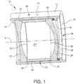
- FIG. 1 depicts an example mounting system, generally indicated at 10, incorporating the details needed to utilize a glass spacer of embodiments of the present disclosure disposed along an optical axis A.
- Glass has a CTE of approximately 4-9 ppm/°C, which is significantly less than aluminum.
- a low CTE borosilicate glass e.g., PYREX® brand glass
- the mounting system 10 includes a cylindrical housing 12 having an outer surface 14 and an inner surface 16.
- the inner surface 14 of the housing 12 includes a lens seat 18. which is configured to retain a lens assembly, generally indicated at 20, when inserting the lens assembly into an interior of the housing.
- the lens assembly 20 includes a first lens 22, a second lens 24, a cylindrical glass spacer 26 positioned between the first lens and the second lens, and a retention assembly, generally indicated at 28.
- the first lens 22 includes a flat portion 30 that engages an annular edge 32 of the glass spacer 26.
- the second lens 24 includes a flat portion 34 that engages an opposite annular edge 36 of the glass spacer 26.
- the first lens 22, glass spacer 26 and the second lens 24 are held in place by the retention assembly 28, which in one embodiment includes a retaining ring 38 and an O-ring 40 disposed between the second lens and the retaining ring.
- the retention assembly 28 which in one embodiment includes a retaining ring 38 and an O-ring 40 disposed between the second lens and the retaining ring.
- this gap 42 is filled by a suitable material, e.g., epoxy, by a port 44 formed in the housing 12. The epoxy holds the glass spacer 26 in place when the epoxy hard
- the glass spacer 26 is sits directly on the flat portions 30, 34 of the respective first and second lenses 22, 24.
- the glass spacer 26 can also be used with the lenses mounted in cells, with the glass spacer being seated on surfaces of the cells instead of directly on the flat portions 30, 34 of the respective first and second lenses 22, 24.
- the glass spacer 26 has an inner diameter of 90 millimeter (mm) and an outer diameter of 100 mm. It should be understood that the mounting assembly 10 may be configured to secure lenses of varying shapes and sizes and still fall within the scope of the instant disclosure.
- the mounting system 10 includes a compression mechanism in the form of the retention assembly 28 along the optical axis A, which holds the first and second lenses 22, 24 and the glass spacer 26 tightly against each other, as an aluminum housing would expand faster over temperature than the low CTE glass spacer.
- This compression mechanism embodies the compressed O-ring 40 of the retention assembly 28 in FIG. 1 .
- the retaining ring 38 compresses the O-ring 40 against the second or front lens 24, which pushes on the glass spacer 26, which in turn pushes on the first or back lens 22, which, finally, sits on the mounting surface or seat 18 machined in the housing 12.
- the mounting mechanism which are lens dependent.
- the key information is the use of a compliant compressive mounting mechanism holding the lens assembly 20 tightly together over temperature. Other mechanisms and approaches that can accomplish this are spring loading, flexure mounting, and epoxy bonding with appropriate details to cause compression loading of the lenses during bonding.
- the oversized gap 42 allows the glass spacer 26 in all its variations of outer diameter, ellipticity, etc. to fit within the housing 12.
- the provision of the glass spacer 26 positioned within the oversized housing 12 causes the glass spacer to rattle around during use, causing particle generation, potentially wearing of the accurately finished faces of the glass spacer, and possible breakage of the glass spacer. Compliant lateral support of the glass spacer 26 within the housing 12 addresses this issue.
- This lateral support can be achieved by the epoxy port holes 44 on the outer surface 14 of the housing 12, and injecting epoxy after alignment is complete.
- Other mechanisms could alternatively be employed, including flexures between the housing 12 and glass spacer 26, or O-ring(s) between the housing and the glass spacer. It could be possible to have the flexures built into the housing itself, causing the housing itself to be compliant.
- the elements contacting the glass spacer 26 require oversized mounting surfaces, shown as lens flats 30, 34 in FIG. 1 , compared to typical optical systems.
- the larger mounting surfaces are required to accommodate the range of outer diameter, wall thickness and other tolerances of the glass spacer.
- the mounting surfaces of the glass spacer 26 need to be set to the correct separation and parallelism. This is part of the glass spacer 26 most probably needs to be done by a standard glass piano process, as the standard glass tubing tolerances are not typically sufficient to meet optical performance.
- the glass spacer 26 would have both of its faces ground, and perhaps polished, to achieve the required thickness and parallelism for the optical system.
- FIG. 2 illustrates a lens assembly, generally indicated at 50, of an embodiment of the present disclosure.
- the lens assembly 50 includes an elongate, cylindrical housing 52 having an outer surface 54 and an inner surface 56.
- the housing 52 is configured to support a plurality of lenses, e.g., lenses 58, 60, 62, 63, 64, 66, 73 within an interior of the housing along optical axis B.
- a cylindrical glass spacer 68 is positioned between the lens 60 and lens 62. and a first retention assembly 70 configured to secure lens 60, and a second retention assembly 72 configured to secure lens 62.
- spacer 68 may be fabricated from a low CTE borosilicate glass.
- An end cap 74 and an O-ring 76 are provided to close an open end of the housing 52 near lens 58.
- this gap 78 is filled by a suitable material, e.g., epoxy, by a port 80 formed in the housing 52.
- the epoxy holds the glass spacer 68 in place when the epoxy hardens.
- the oversized gap 78 allows the glass spacer 68 in all its variations of outer diameter, ellipticity, etc. to fit within the housing 52.
- Compliant lateral support of the glass spacer 68 within the housing 52 is achieved by the epoxy port holes 80 on the outer surface 54 of the housing 52, and injecting epoxy after alignment is complete.
- FIG. 3 illustrates a lens assembly, generally indicated at 90, of another embodiment of the present disclosure.
- the lens assembly 90 includes an elongate, cylindrical housing 92 having an outer surface 94 and an inner surface 96.
- the housing 92 is configured to support a plurality of lenses, e.g., lenses 98, 100 within an interior of the housing along optical axis C.
- a cylindrical glass spacer 102 and an aluminum spacer 104 are positioned between the lens 98 and lens 100, and a retention assembly generally indicated at 70 configured to secure lenses and spacers in place.
- the glass spacer 102 and the aluminum spacer 104 are positioned next to one another and coaxial along optical axis C.
- lens 98 includes a flat portion that engages an annular edge of the glass spacer 102.
- lens 100 includes a flat portion that engages an annular edge of the aluminum spacer 104.
- the retention assembly includes a retaining ring 108 and an O-ring 110.
- glass spacer 102 may be fabricated from a low CTE borosilicate glass.
- the aluminum spacer may 104 may be fabricated from aluminum or an aluminum alloy.
- the overall thermal effect of the spacer can be manipulated to achieve a desired CTE.
- a 5 mm aluminum spacer positioned adjacent a 5 mm glass (Pyrex) spacer in the manner illustrated in FIG. 3 provides an equivalent of a 10 mm spacer that has a CTE of 13.95 ppm/°C.
- the provision of a 2 mm aluminum spacer with 8 mm glass (Pyrex) spacer provides an equivalent of a 10 mm spacer that has a CTE of 7.56 ppm/°C.
- the athermalization of an existing system may be manipulated by adjusting a ratio of the lengths of the two spacers, thereby providing a method of compensating for unexpected thermal behavior within the assembly 90.
Landscapes
- Physics & Mathematics (AREA)
- General Physics & Mathematics (AREA)
- Optics & Photonics (AREA)
- Lens Barrels (AREA)
Description
- A thermal lens systems require a thermal expansion of lens mounts to be counteracted by a change in optical properties of the lens, causing the lenses to remain in focus as the temperature of the lens system changes. Aluminum is commonly used as a lens mount material due to its low inherent cost (inexpensive material and processing costs). However, aluminum has one of the highest coefficient of thermal expansion (CTE) for metals (around 24 ppm/°C). This high CTE frequently results in lens designs are difficult to correct optically.
- Glass spacers are also known in the art of lens mounts. Reference may be made to
U.S. Patent Nos. 5,100,218 and6,185,040 for lens mounts using glass spacers. - A main embodiment of the present invention is defined in claim 1. Another main embodiment is defined in claim 5. Additional embodiments are defined in the dependent claims.
- Various aspects of at least one embodiment are discussed below with reference to the accompanying figures, which are not intended to be drawn to scale. The figures are included to provide illustration and a further understanding of the various aspects and embodiments, and are incorporated in and constitute a part of this specification, but are not intended as a definition of the limits of the invention. Where technical features in the figures, detailed description or any claim are followed by references signs, the reference signs have been included for the sole purpose of increasing the intelligibility of the figures and description. In the figures, each identical or nearly identical component that is illustrated in various figures is represented by a like numeral. For purposes of clarity, not every component may be labeled in every figure. In the figures:
-
FIG. 1 is a cross sectional view of a mounting system incorporating a glass spacer according to an embodiment of the present disclosure; -
FIG. 2 is a cross sectional view of a lens assembly including a mounting system of another embodiment of the present disclosure; and -
FIG. 3 is a cross sectional view of a lens assembly including a mounting system of yet another embodiment of the present disclosure. - Aspects and embodiments are directed to selectively choosing a lower CTE material for spacers between certain lenses, by which the optical design can be simplified. The present disclosure is directed to using low CTE glass piping (a low cost material) with standard piano glass processing to create inexpensive low CTE lens spacers for thermal optical systems. These spacers and this arrangement can result in substantial cost savings for optomechanics while delivering better repeatability and stability than aluminum and plastic spacers that are commonly used.
- It is to be appreciated that embodiments of the methods and apparatuses discussed herein are not limited in application to the details of construction and the arrangement of components set forth in the following description or illustrated in the accompanying drawings. The methods and apparatuses are capable of implementation in other embodiments and of being practiced or of being carried out in various ways. Examples of specific implementations are provided herein for illustrative purposes only and are not intended to be limiting. In particular, acts, elements and features discussed in connection with any one or more embodiments are not intended to be excluded from a similar role in any other embodiment.
- Also, the phraseology and terminology used herein is for the purpose of description and should not be regarded as limiting. Any references to embodiments or elements or acts of the systems and methods herein referred to in the singular may also embrace embodiments including a plurality of these elements, and any references in plural to any embodiment or element or act herein may also embrace embodiments including only a single element. The use herein of "including," "comprising," "having," "containing," "involving," and variations thereof is meant to encompass the items listed thereafter and equivalents thereof as well as additional items. References to "or" may be construed as inclusive so that any terms described using "or" may indicate any of a single, more than one, and all of the described terms. Any references to front and back, left and right, top and bottom, upper and lower, and vertical and horizontal are intended for convenience of description, not to limit the present systems and methods or their components to any one positional or spatial orientation.
- Standard glass tubing is typically produced by an extruding process, which results in a product that is inexpensive, but without the tight mechanical tolerances normally associated with optical systems. The parallelism of the cut faces, the inner and outer diameters, bending and ellipticity of the glass tubing are all examples of non-ideal characteristics that glass tubing exhibits, making it difficult to incorporate glass tubing as a mechanical spacer. These loose tolerances can be accommodated by the mechanical system that is the lens body. The use of an oversized metal housing in which the glass spacer resides, with generous flats on the lenses or cells that contact the face of the glass tubing, provides part of the solution in utilizing glass tubing as a spacer element. The addition of epoxy ports in the metal housing around the glass spacer can be used to bond in the space between the outer diameter of the glass tubing and the inner diameter of the metal housing limits lateral shifts of the glass spacer. Finally, the use of a compressed O-ring to "spring" load the lenses against glass spacer completes the mechanical system that accommodates the loose tolerances associated with glass tubing.
- The parallelism issue of the glass tubing, and setting the correct length can be accomplished via standard plano optics polishing, where the tube is bonded to a fixture and ground or polished on both ends to achieve the requisite length and end parallelism.
- The use of glass tubing as a low CTE mechanical spacer, with the mechanical details listed above to solve the loose tolerances that the glass tubing exhibits. Embodiments include:
- 1) a mechanical spacer (mechanical element setting the distance between two optical elements) made of glass tubing or other low CTE material tubing; and
- 2) a mechanical system that accommodates loose tolerances in the mechanical spacer in dimensions other than the length and parallelism of the faces controlling the tilt of the optical elements
- a. oversized outer housing accommodating tubing outer diameter (OD), ellipticity, tilt and bending tolerances,
- b. compliant method of securing a loose fitting spacer within the housing: epoxy ports in outer housing, a compressible O-ring disposed between tubing and housing, flexures positioned between housing and spacer, etc.,
- c. oversized mechanical seats on optical/mechanical elements in contact with faces of the spacer accommodating tubing OD, ellipticity, tilt and bending tolerances, and
- d. a mechanical method of compressing an optical system (along the local optical axis) against spacer to accommodate CTE difference in housing and the spacer:
compressed O-ring lens/mount, spring/flexure mounted optics, bonded optics with appropriate mechanical details to provide compression loading of the system when adhesive cures.
-
FIG. 1 depicts an example mounting system, generally indicated at 10, incorporating the details needed to utilize a glass spacer of embodiments of the present disclosure disposed along an optical axis A. Glass has a CTE of approximately 4-9 ppm/°C, which is significantly less than aluminum. In one embodiment, a low CTE borosilicate glass (e.g., PYREX® brand glass) having a CTE of 3.3 ppm//°C may be employed. As shown, themounting system 10 includes acylindrical housing 12 having anouter surface 14 and aninner surface 16. Theinner surface 14 of thehousing 12 includes alens seat 18. which is configured to retain a lens assembly, generally indicated at 20, when inserting the lens assembly into an interior of the housing. In one embodiment, thelens assembly 20 includes afirst lens 22, asecond lens 24, acylindrical glass spacer 26 positioned between the first lens and the second lens, and a retention assembly, generally indicated at 28. Thefirst lens 22 includes aflat portion 30 that engages anannular edge 32 of theglass spacer 26. Similarly, thesecond lens 24 includes aflat portion 34 that engages an oppositeannular edge 36 of theglass spacer 26. Thefirst lens 22,glass spacer 26 and thesecond lens 24 are held in place by theretention assembly 28, which in one embodiment includes aretaining ring 38 and an O-ring 40 disposed between the second lens and the retaining ring. As shown inFIG. 1 , there is agap 42 between thehousing 12 and theglass spacer 26. In one embodiment, thisgap 42 is filled by a suitable material, e.g., epoxy, by aport 44 formed in thehousing 12. The epoxy holds theglass spacer 26 in place when the epoxy hardens. - In one embodiment, which is illustrated in
FIG. 1 , theglass spacer 26 is sits directly on theflat portions second lenses glass spacer 26 can also be used with the lenses mounted in cells, with the glass spacer being seated on surfaces of the cells instead of directly on theflat portions second lenses glass spacer 26 has an inner diameter of 90 millimeter (mm) and an outer diameter of 100 mm. It should be understood that the mountingassembly 10 may be configured to secure lenses of varying shapes and sizes and still fall within the scope of the instant disclosure. - As discussed above, the mounting
system 10 includes a compression mechanism in the form of theretention assembly 28 along the optical axis A, which holds the first andsecond lenses glass spacer 26 tightly against each other, as an aluminum housing would expand faster over temperature than the low CTE glass spacer. This compression mechanism embodies the compressed O-ring 40 of theretention assembly 28 inFIG. 1 . The retainingring 38 compresses the O-ring 40 against the second orfront lens 24, which pushes on theglass spacer 26, which in turn pushes on the first or backlens 22, which, finally, sits on the mounting surface orseat 18 machined in thehousing 12. There are numerous variants of the mounting mechanism, which are lens dependent. The key information is the use of a compliant compressive mounting mechanism holding thelens assembly 20 tightly together over temperature. Other mechanisms and approaches that can accomplish this are spring loading, flexure mounting, and epoxy bonding with appropriate details to cause compression loading of the lenses during bonding. - Another aspect of the mounting
system 10 is theoversized gap 42 between theinner surface 16 of thehousing 12 and anouter surface 46 theglass spacer 26. Due to the loose tolerances on commodity glass tubing a tight fit (tighter than 0.1 mm) is not possible without the potential of the parts not fitting together. Theoversized gap 42 allows theglass spacer 26 in all its variations of outer diameter, ellipticity, etc. to fit within thehousing 12. The provision of theglass spacer 26 positioned within theoversized housing 12 causes the glass spacer to rattle around during use, causing particle generation, potentially wearing of the accurately finished faces of the glass spacer, and possible breakage of the glass spacer. Compliant lateral support of theglass spacer 26 within thehousing 12 addresses this issue. This lateral support can be achieved by the epoxy port holes 44 on theouter surface 14 of thehousing 12, and injecting epoxy after alignment is complete. Other mechanisms could alternatively be employed, including flexures between thehousing 12 andglass spacer 26, or O-ring(s) between the housing and the glass spacer. It could be possible to have the flexures built into the housing itself, causing the housing itself to be compliant. - The elements sitting on the
annular surfaces glass spacer 26, which, in the embodiment shown inFIG. 1 is the lenses themselves, may embody other spacers or cells holding the lenses. The elements contacting theglass spacer 26 require oversized mounting surfaces, shown aslens flats FIG. 1 , compared to typical optical systems. The larger mounting surfaces are required to accommodate the range of outer diameter, wall thickness and other tolerances of the glass spacer. - Finally, the mounting surfaces of the
glass spacer 26 need to be set to the correct separation and parallelism. This is part of theglass spacer 26 most probably needs to be done by a standard glass piano process, as the standard glass tubing tolerances are not typically sufficient to meet optical performance. Theglass spacer 26 would have both of its faces ground, and perhaps polished, to achieve the required thickness and parallelism for the optical system. -
FIG. 2 illustrates a lens assembly, generally indicated at 50, of an embodiment of the present disclosure. As shown, thelens assembly 50 includes an elongate,cylindrical housing 52 having anouter surface 54 and aninner surface 56. Thehousing 52 is configured to support a plurality of lenses, e.g.,lenses cylindrical glass spacer 68 is positioned between thelens 60 andlens 62. and afirst retention assembly 70 configured to securelens 60, and asecond retention assembly 72 configured to securelens 62. As withspacer 26,spacer 68 may be fabricated from a low CTE borosilicate glass. - An
end cap 74 and an O-ring 76 are provided to close an open end of thehousing 52 nearlens 58. As shown inFIG. 2 , there is agap 78 between thehousing 52 and theglass spacer 68 In one embodiment, thisgap 78 is filled by a suitable material, e.g., epoxy, by aport 80 formed in thehousing 52. As with mountingsystem 10, the epoxy holds theglass spacer 68 in place when the epoxy hardens. Theoversized gap 78 allows theglass spacer 68 in all its variations of outer diameter, ellipticity, etc. to fit within thehousing 52. Compliant lateral support of theglass spacer 68 within thehousing 52 is achieved by the epoxy port holes 80 on theouter surface 54 of thehousing 52, and injecting epoxy after alignment is complete. -
FIG. 3 illustrates a lens assembly, generally indicated at 90, of another embodiment of the present disclosure. As shown, thelens assembly 90 includes an elongate,cylindrical housing 92 having anouter surface 94 and aninner surface 96. Thehousing 92 is configured to support a plurality of lenses, e.g.,lenses cylindrical glass spacer 102 and analuminum spacer 104 are positioned between thelens 98 andlens 100, and a retention assembly generally indicated at 70 configured to secure lenses and spacers in place. As shown, theglass spacer 102 and thealuminum spacer 104 are positioned next to one another and coaxial along optical axis C. As withlens assembly 20,lens 98 includes a flat portion that engages an annular edge of theglass spacer 102. Similarly,lens 100 includes a flat portion that engages an annular edge of thealuminum spacer 104. - The retention assembly includes a retaining
ring 108 and an O-ring 110. As withspacers glass spacer 102 may be fabricated from a low CTE borosilicate glass. The aluminum spacer may 104 may be fabricated from aluminum or an aluminum alloy. As shown, there is agap 112 between thehousing 92 and theglass spacer 102. In one embodiment, thisgap 112 may be filled by a suitable material, e.g., epoxy, by a port formed in thehousing 52. - By providing the
glass spacer 102 and thealuminum spacer 104, the overall thermal effect of the spacer can be manipulated to achieve a desired CTE. For example, the provision of a 5 mm aluminum spacer positioned adjacent a 5 mm glass (Pyrex) spacer in the manner illustrated inFIG. 3 provides an equivalent of a 10 mm spacer that has a CTE of 13.95 ppm/°C. In another example, the provision of a 2 mm aluminum spacer with 8 mm glass (Pyrex) spacer provides an equivalent of a 10 mm spacer that has a CTE of 7.56 ppm/°C. As described, by selecting the sizes (lengths and thicknesses) of the glass andaluminum spacers assembly 90.
Claims (7)
- An optical assembly comprising:a housing (12) having an interior region and including a port (44) providing fluid communication from an exterior of the housing to the interior region of the housing;a first lens (22) disposed within the interior region of the housing;a second lens (24) disposed within the interior region of the housing, the second lens being spaced from the first lens;a spacer (26) disposed within the interior region of the housing between the first lens and the second lens, the spacer being fabricated from glass material; anda retention assembly (28) configured to engage the second lens when assembled to retain the first lens, the spacer and the second lens in placewherein the first lens and the second lens each have a flat portion (30, 34) that is configured to engage the spacer, further comprising a filler material which is disposed through the port in a space defined by an exterior surface of the spacer and an interior surface of the housing.
- The optical assembly of claim 1, wherein the retention assembly includes an O-ring (40) positioned to engage the second lens and preferably wherein the retention assembly further includes a retaining ring (38) positioned to engage the O-ring.
- The optical assembly of claim 1, wherein the filler material includes an epoxy material.
- The optical assembly of claim 1, wherein an interior surface of the housing has a seat (18) formed therein, and wherein the first lens is disposed within the interior region of the housing against the seat.
- A method of assembling an optical assembly, the method comprising:positioning a first lens within a housing having an interior region and a port providing fluid communication from an exterior of the housing to the interior region of the housing;positioning a spacer fabricated from glass material within the interior region of the housing so that the spacer engages the first lens;positioning a second lens within the interior region of the housing so that the second lens engages the spacer;securing the first lens, the spacer and the second lens with a retention assembly configured to engage the second lens when assembled to retain the first lens, the spacer and the second lens in place, wherein the first lens and the second lens each have a flat portion that is configured to engage the spacer; and.depositing a filler material in a space defined by an exterior surface of the spacer and an interior surface of the housing, the filler material being deposited in the space through the port.
- The method of claim 5, wherein the retention assembly includes an O-ring positioned to engage the second lens and a retaining ring positioned to engage the O-ring.
- The method of claim 5, wherein an interior surface of the housing has a seat formed therein, and wherein the first lens is disposed within the interior region of the housing against the seat.
Applications Claiming Priority (2)
| Application Number | Priority Date | Filing Date | Title |
|---|---|---|---|
| US201261740029P | 2012-12-20 | 2012-12-20 | |
| PCT/CA2013/001037 WO2014094118A1 (en) | 2012-12-20 | 2013-12-13 | Optical assembly |
Publications (3)
| Publication Number | Publication Date |
|---|---|
| EP2936230A1 EP2936230A1 (en) | 2015-10-28 |
| EP2936230A4 EP2936230A4 (en) | 2016-11-16 |
| EP2936230B1 true EP2936230B1 (en) | 2020-05-27 |
Family
ID=50977452
Family Applications (1)
| Application Number | Title | Priority Date | Filing Date |
|---|---|---|---|
| EP13864058.6A Active EP2936230B1 (en) | 2012-12-20 | 2013-12-13 | Optical assembly |
Country Status (3)
| Country | Link |
|---|---|
| US (1) | US20160195690A1 (en) |
| EP (1) | EP2936230B1 (en) |
| WO (1) | WO2014094118A1 (en) |
Families Citing this family (6)
| Publication number | Priority date | Publication date | Assignee | Title |
|---|---|---|---|---|
| CN104375253B (en) * | 2014-11-17 | 2017-01-25 | 中国科学院光电技术研究所 | Device and method for improving mechanical stability of imaging optical lens |
| US20170276897A1 (en) * | 2016-03-25 | 2017-09-28 | Ravi Nalla | Enhanced lens assembly |
| JP7542959B2 (en) * | 2019-12-06 | 2024-09-02 | キヤノン株式会社 | Lens Retention Mechanism |
| DE102021119298B4 (en) | 2021-07-26 | 2025-03-27 | Carl Zeiss Meditec Ag | Contactless visualization system for a surgical microscope for ophthalmic surgery |
| DE102021119297B4 (en) | 2021-07-26 | 2025-03-27 | Carl Zeiss Meditec Ag | Contactless visualization system for a surgical microscope for ophthalmic surgery |
| CN114637126B (en) * | 2022-05-18 | 2022-09-13 | 江西联创电子有限公司 | Optical image stabilizing lens and assembling method thereof |
Family Cites Families (5)
| Publication number | Priority date | Publication date | Assignee | Title |
|---|---|---|---|---|
| EP0139979B1 (en) * | 1983-10-19 | 1988-11-09 | The Perkin-Elmer Corporation | Optical assemblies |
| GB8811980D0 (en) * | 1988-05-20 | 1988-11-16 | Pilkington Perkin Elmer Ltd | Thermal imaging optical system |
| US6185040B1 (en) * | 1995-07-26 | 2001-02-06 | Fujitsu Limited | Virtually imaged phased array (VIPA) having spacer element and optical length adjusting element |
| US7088530B1 (en) * | 2005-01-28 | 2006-08-08 | Eastman Kodak Company | Passively aligned optical elements |
| WO2010061604A1 (en) * | 2008-11-28 | 2010-06-03 | 住友電気工業株式会社 | Lens unit and infrared lens unit for mounting on vehicle |
-
2013
- 2013-12-13 US US14/651,807 patent/US20160195690A1/en not_active Abandoned
- 2013-12-13 EP EP13864058.6A patent/EP2936230B1/en active Active
- 2013-12-13 WO PCT/CA2013/001037 patent/WO2014094118A1/en not_active Ceased
Non-Patent Citations (1)
| Title |
|---|
| None * |
Also Published As
| Publication number | Publication date |
|---|---|
| EP2936230A1 (en) | 2015-10-28 |
| WO2014094118A1 (en) | 2014-06-26 |
| EP2936230A4 (en) | 2016-11-16 |
| US20160195690A1 (en) | 2016-07-07 |
Similar Documents
| Publication | Publication Date | Title |
|---|---|---|
| US20160195690A1 (en) | Optical assembly | |
| US7088530B1 (en) | Passively aligned optical elements | |
| JP5798245B2 (en) | Fiber horizontal insertion type ferrule assembly | |
| US10175395B2 (en) | Mount for an optical structure having a grooved protruding member and method of mounting an optical structure using such mount | |
| CN101713855B (en) | Lens frame, lens assembly and image-taking apparatus | |
| US20040179277A1 (en) | Precisely aligned lens structure and a method for its fabrication | |
| JP2018510385A (en) | Optical assembly having a translatable and centered sleeve | |
| US10222580B2 (en) | Mounts for an optical structure having a grooved protruding member with a damping ring disposed in or on the groove and methods of mounting an optical structure using such mounts | |
| JPWO2010007692A1 (en) | Hinges for spectacles and spectacle frame with the same | |
| CN101609188A (en) | The camera lens module | |
| EP3304160B1 (en) | Monolithic optical mounting element | |
| CN104035176A (en) | Supporting structure of large-caliber telescope secondary mirror chamber | |
| EP4049078B1 (en) | Mount assembly for an optical structure and corresponding mounting method | |
| EP2638418B1 (en) | Force-insensitive fabry-perot etalon | |
| CN211348826U (en) | High stability secondary mirror bearing structure | |
| US20120050894A1 (en) | Lens barrel and manufacturing method of the same | |
| EP1876485A1 (en) | Combination lens and method for manufacturing same | |
| WO2015053626A2 (en) | Device for placing at least two rigid lenses and/or mirrors coaxially relative to each other, a lens mount assembly comprising such device, and a manufacturing method therefor | |
| US20210389554A1 (en) | Low profile hollow retroreflector assembly and their mounting structures and mounting methods | |
| US6978065B2 (en) | Ruggedized optical fiber collimator | |
| TW200846736A (en) | Lens barrel and lens module having the same | |
| JP7224250B2 (en) | Lens mount and barrel | |
| CN219758596U (en) | Glasses plate structure | |
| US20150098129A1 (en) | Generating mechanical features on an optical component | |
| Vukobratovich et al. | Techniques for Mounting Prisms |
Legal Events
| Date | Code | Title | Description |
|---|---|---|---|
| PUAI | Public reference made under article 153(3) epc to a published international application that has entered the european phase |
Free format text: ORIGINAL CODE: 0009012 |
|
| 17P | Request for examination filed |
Effective date: 20150318 |
|
| AK | Designated contracting states |
Kind code of ref document: A1 Designated state(s): AL AT BE BG CH CY CZ DE DK EE ES FI FR GB GR HR HU IE IS IT LI LT LU LV MC MK MT NL NO PL PT RO RS SE SI SK SM TR |
|
| AX | Request for extension of the european patent |
Extension state: BA ME |
|
| DAX | Request for extension of the european patent (deleted) | ||
| RIC1 | Information provided on ipc code assigned before grant |
Ipc: G02B 27/02 20060101ALI20160630BHEP Ipc: G02B 27/00 20060101ALI20160630BHEP Ipc: G02B 7/02 20060101AFI20160630BHEP |
|
| A4 | Supplementary search report drawn up and despatched |
Effective date: 20161018 |
|
| RIC1 | Information provided on ipc code assigned before grant |
Ipc: G02B 7/02 20060101AFI20161012BHEP Ipc: G02B 27/00 20060101ALI20161012BHEP Ipc: G02B 27/02 20060101ALI20161012BHEP |
|
| STAA | Information on the status of an ep patent application or granted ep patent |
Free format text: STATUS: EXAMINATION IS IN PROGRESS |
|
| 17Q | First examination report despatched |
Effective date: 20190122 |
|
| GRAP | Despatch of communication of intention to grant a patent |
Free format text: ORIGINAL CODE: EPIDOSNIGR1 |
|
| STAA | Information on the status of an ep patent application or granted ep patent |
Free format text: STATUS: GRANT OF PATENT IS INTENDED |
|
| INTG | Intention to grant announced |
Effective date: 20190712 |
|
| GRAJ | Information related to disapproval of communication of intention to grant by the applicant or resumption of examination proceedings by the epo deleted |
Free format text: ORIGINAL CODE: EPIDOSDIGR1 |
|
| STAA | Information on the status of an ep patent application or granted ep patent |
Free format text: STATUS: EXAMINATION IS IN PROGRESS |
|
| GRAP | Despatch of communication of intention to grant a patent |
Free format text: ORIGINAL CODE: EPIDOSNIGR1 |
|
| STAA | Information on the status of an ep patent application or granted ep patent |
Free format text: STATUS: GRANT OF PATENT IS INTENDED |
|
| INTC | Intention to grant announced (deleted) | ||
| INTG | Intention to grant announced |
Effective date: 20191220 |
|
| GRAS | Grant fee paid |
Free format text: ORIGINAL CODE: EPIDOSNIGR3 |
|
| GRAA | (expected) grant |
Free format text: ORIGINAL CODE: 0009210 |
|
| STAA | Information on the status of an ep patent application or granted ep patent |
Free format text: STATUS: THE PATENT HAS BEEN GRANTED |
|
| AK | Designated contracting states |
Kind code of ref document: B1 Designated state(s): AL AT BE BG CH CY CZ DE DK EE ES FI FR GB GR HR HU IE IS IT LI LT LU LV MC MK MT NL NO PL PT RO RS SE SI SK SM TR |
|
| REG | Reference to a national code |
Ref country code: GB Ref legal event code: FG4D |
|
| REG | Reference to a national code |
Ref country code: CH Ref legal event code: EP |
|
| REG | Reference to a national code |
Ref country code: AT Ref legal event code: REF Ref document number: 1275131 Country of ref document: AT Kind code of ref document: T Effective date: 20200615 |
|
| REG | Reference to a national code |
Ref country code: DE Ref legal event code: R096 Ref document number: 602013069499 Country of ref document: DE |
|
| REG | Reference to a national code |
Ref country code: LT Ref legal event code: MG4D |
|
| PG25 | Lapsed in a contracting state [announced via postgrant information from national office to epo] |
Ref country code: PT Free format text: LAPSE BECAUSE OF FAILURE TO SUBMIT A TRANSLATION OF THE DESCRIPTION OR TO PAY THE FEE WITHIN THE PRESCRIBED TIME-LIMIT Effective date: 20200928 Ref country code: NO Free format text: LAPSE BECAUSE OF FAILURE TO SUBMIT A TRANSLATION OF THE DESCRIPTION OR TO PAY THE FEE WITHIN THE PRESCRIBED TIME-LIMIT Effective date: 20200827 Ref country code: IS Free format text: LAPSE BECAUSE OF FAILURE TO SUBMIT A TRANSLATION OF THE DESCRIPTION OR TO PAY THE FEE WITHIN THE PRESCRIBED TIME-LIMIT Effective date: 20200927 Ref country code: SE Free format text: LAPSE BECAUSE OF FAILURE TO SUBMIT A TRANSLATION OF THE DESCRIPTION OR TO PAY THE FEE WITHIN THE PRESCRIBED TIME-LIMIT Effective date: 20200527 Ref country code: GR Free format text: LAPSE BECAUSE OF FAILURE TO SUBMIT A TRANSLATION OF THE DESCRIPTION OR TO PAY THE FEE WITHIN THE PRESCRIBED TIME-LIMIT Effective date: 20200828 Ref country code: FI Free format text: LAPSE BECAUSE OF FAILURE TO SUBMIT A TRANSLATION OF THE DESCRIPTION OR TO PAY THE FEE WITHIN THE PRESCRIBED TIME-LIMIT Effective date: 20200527 Ref country code: LT Free format text: LAPSE BECAUSE OF FAILURE TO SUBMIT A TRANSLATION OF THE DESCRIPTION OR TO PAY THE FEE WITHIN THE PRESCRIBED TIME-LIMIT Effective date: 20200527 |
|
| REG | Reference to a national code |
Ref country code: NL Ref legal event code: MP Effective date: 20200527 |
|
| PG25 | Lapsed in a contracting state [announced via postgrant information from national office to epo] |
Ref country code: BG Free format text: LAPSE BECAUSE OF FAILURE TO SUBMIT A TRANSLATION OF THE DESCRIPTION OR TO PAY THE FEE WITHIN THE PRESCRIBED TIME-LIMIT Effective date: 20200827 Ref country code: LV Free format text: LAPSE BECAUSE OF FAILURE TO SUBMIT A TRANSLATION OF THE DESCRIPTION OR TO PAY THE FEE WITHIN THE PRESCRIBED TIME-LIMIT Effective date: 20200527 Ref country code: HR Free format text: LAPSE BECAUSE OF FAILURE TO SUBMIT A TRANSLATION OF THE DESCRIPTION OR TO PAY THE FEE WITHIN THE PRESCRIBED TIME-LIMIT Effective date: 20200527 Ref country code: RS Free format text: LAPSE BECAUSE OF FAILURE TO SUBMIT A TRANSLATION OF THE DESCRIPTION OR TO PAY THE FEE WITHIN THE PRESCRIBED TIME-LIMIT Effective date: 20200527 |
|
| REG | Reference to a national code |
Ref country code: AT Ref legal event code: MK05 Ref document number: 1275131 Country of ref document: AT Kind code of ref document: T Effective date: 20200527 |
|
| PG25 | Lapsed in a contracting state [announced via postgrant information from national office to epo] |
Ref country code: AL Free format text: LAPSE BECAUSE OF FAILURE TO SUBMIT A TRANSLATION OF THE DESCRIPTION OR TO PAY THE FEE WITHIN THE PRESCRIBED TIME-LIMIT Effective date: 20200527 Ref country code: NL Free format text: LAPSE BECAUSE OF FAILURE TO SUBMIT A TRANSLATION OF THE DESCRIPTION OR TO PAY THE FEE WITHIN THE PRESCRIBED TIME-LIMIT Effective date: 20200527 |
|
| PG25 | Lapsed in a contracting state [announced via postgrant information from national office to epo] |
Ref country code: RO Free format text: LAPSE BECAUSE OF FAILURE TO SUBMIT A TRANSLATION OF THE DESCRIPTION OR TO PAY THE FEE WITHIN THE PRESCRIBED TIME-LIMIT Effective date: 20200527 Ref country code: CZ Free format text: LAPSE BECAUSE OF FAILURE TO SUBMIT A TRANSLATION OF THE DESCRIPTION OR TO PAY THE FEE WITHIN THE PRESCRIBED TIME-LIMIT Effective date: 20200527 Ref country code: ES Free format text: LAPSE BECAUSE OF FAILURE TO SUBMIT A TRANSLATION OF THE DESCRIPTION OR TO PAY THE FEE WITHIN THE PRESCRIBED TIME-LIMIT Effective date: 20200527 Ref country code: SM Free format text: LAPSE BECAUSE OF FAILURE TO SUBMIT A TRANSLATION OF THE DESCRIPTION OR TO PAY THE FEE WITHIN THE PRESCRIBED TIME-LIMIT Effective date: 20200527 Ref country code: AT Free format text: LAPSE BECAUSE OF FAILURE TO SUBMIT A TRANSLATION OF THE DESCRIPTION OR TO PAY THE FEE WITHIN THE PRESCRIBED TIME-LIMIT Effective date: 20200527 Ref country code: DK Free format text: LAPSE BECAUSE OF FAILURE TO SUBMIT A TRANSLATION OF THE DESCRIPTION OR TO PAY THE FEE WITHIN THE PRESCRIBED TIME-LIMIT Effective date: 20200527 Ref country code: EE Free format text: LAPSE BECAUSE OF FAILURE TO SUBMIT A TRANSLATION OF THE DESCRIPTION OR TO PAY THE FEE WITHIN THE PRESCRIBED TIME-LIMIT Effective date: 20200527 |
|
| PG25 | Lapsed in a contracting state [announced via postgrant information from national office to epo] |
Ref country code: SK Free format text: LAPSE BECAUSE OF FAILURE TO SUBMIT A TRANSLATION OF THE DESCRIPTION OR TO PAY THE FEE WITHIN THE PRESCRIBED TIME-LIMIT Effective date: 20200527 Ref country code: PL Free format text: LAPSE BECAUSE OF FAILURE TO SUBMIT A TRANSLATION OF THE DESCRIPTION OR TO PAY THE FEE WITHIN THE PRESCRIBED TIME-LIMIT Effective date: 20200527 |
|
| REG | Reference to a national code |
Ref country code: DE Ref legal event code: R097 Ref document number: 602013069499 Country of ref document: DE |
|
| PLBE | No opposition filed within time limit |
Free format text: ORIGINAL CODE: 0009261 |
|
| STAA | Information on the status of an ep patent application or granted ep patent |
Free format text: STATUS: NO OPPOSITION FILED WITHIN TIME LIMIT |
|
| 26N | No opposition filed |
Effective date: 20210302 |
|
| PG25 | Lapsed in a contracting state [announced via postgrant information from national office to epo] |
Ref country code: SI Free format text: LAPSE BECAUSE OF FAILURE TO SUBMIT A TRANSLATION OF THE DESCRIPTION OR TO PAY THE FEE WITHIN THE PRESCRIBED TIME-LIMIT Effective date: 20200527 |
|
| REG | Reference to a national code |
Ref country code: CH Ref legal event code: PL |
|
| PG25 | Lapsed in a contracting state [announced via postgrant information from national office to epo] |
Ref country code: MC Free format text: LAPSE BECAUSE OF FAILURE TO SUBMIT A TRANSLATION OF THE DESCRIPTION OR TO PAY THE FEE WITHIN THE PRESCRIBED TIME-LIMIT Effective date: 20200527 |
|
| REG | Reference to a national code |
Ref country code: BE Ref legal event code: MM Effective date: 20201231 |
|
| PG25 | Lapsed in a contracting state [announced via postgrant information from national office to epo] |
Ref country code: LU Free format text: LAPSE BECAUSE OF NON-PAYMENT OF DUE FEES Effective date: 20201213 Ref country code: IE Free format text: LAPSE BECAUSE OF NON-PAYMENT OF DUE FEES Effective date: 20201213 |
|
| PG25 | Lapsed in a contracting state [announced via postgrant information from national office to epo] |
Ref country code: LI Free format text: LAPSE BECAUSE OF NON-PAYMENT OF DUE FEES Effective date: 20201231 Ref country code: CH Free format text: LAPSE BECAUSE OF NON-PAYMENT OF DUE FEES Effective date: 20201231 |
|
| PG25 | Lapsed in a contracting state [announced via postgrant information from national office to epo] |
Ref country code: TR Free format text: LAPSE BECAUSE OF FAILURE TO SUBMIT A TRANSLATION OF THE DESCRIPTION OR TO PAY THE FEE WITHIN THE PRESCRIBED TIME-LIMIT Effective date: 20200527 Ref country code: MT Free format text: LAPSE BECAUSE OF FAILURE TO SUBMIT A TRANSLATION OF THE DESCRIPTION OR TO PAY THE FEE WITHIN THE PRESCRIBED TIME-LIMIT Effective date: 20200527 Ref country code: CY Free format text: LAPSE BECAUSE OF FAILURE TO SUBMIT A TRANSLATION OF THE DESCRIPTION OR TO PAY THE FEE WITHIN THE PRESCRIBED TIME-LIMIT Effective date: 20200527 |
|
| PG25 | Lapsed in a contracting state [announced via postgrant information from national office to epo] |
Ref country code: MK Free format text: LAPSE BECAUSE OF FAILURE TO SUBMIT A TRANSLATION OF THE DESCRIPTION OR TO PAY THE FEE WITHIN THE PRESCRIBED TIME-LIMIT Effective date: 20200527 |
|
| PG25 | Lapsed in a contracting state [announced via postgrant information from national office to epo] |
Ref country code: BE Free format text: LAPSE BECAUSE OF NON-PAYMENT OF DUE FEES Effective date: 20201231 |
|
| P01 | Opt-out of the competence of the unified patent court (upc) registered |
Effective date: 20230603 |
|
| PGFP | Annual fee paid to national office [announced via postgrant information from national office to epo] |
Ref country code: DE Payment date: 20251126 Year of fee payment: 13 |
|
| PGFP | Annual fee paid to national office [announced via postgrant information from national office to epo] |
Ref country code: GB Payment date: 20251120 Year of fee payment: 13 |
|
| PGFP | Annual fee paid to national office [announced via postgrant information from national office to epo] |
Ref country code: IT Payment date: 20251119 Year of fee payment: 13 |
|
| PGFP | Annual fee paid to national office [announced via postgrant information from national office to epo] |
Ref country code: FR Payment date: 20251120 Year of fee payment: 13 |