EP2936072B1 - Optically-powered sensor systems, suitable for deployment on-board aircraft - Google Patents
Optically-powered sensor systems, suitable for deployment on-board aircraft Download PDFInfo
- Publication number
- EP2936072B1 EP2936072B1 EP13828940.0A EP13828940A EP2936072B1 EP 2936072 B1 EP2936072 B1 EP 2936072B1 EP 13828940 A EP13828940 A EP 13828940A EP 2936072 B1 EP2936072 B1 EP 2936072B1
- Authority
- EP
- European Patent Office
- Prior art keywords
- sensor
- optical
- system controller
- aircraft
- fuel tank
- Prior art date
- Legal status (The legal status is an assumption and is not a legal conclusion. Google has not performed a legal analysis and makes no representation as to the accuracy of the status listed.)
- Active
Links
Images


Classifications
-
- G—PHYSICS
- G01—MEASURING; TESTING
- G01J—MEASUREMENT OF INTENSITY, VELOCITY, SPECTRAL CONTENT, POLARISATION, PHASE OR PULSE CHARACTERISTICS OF INFRARED, VISIBLE OR ULTRAVIOLET LIGHT; COLORIMETRY; RADIATION PYROMETRY
- G01J1/00—Photometry, e.g. photographic exposure meter
- G01J1/02—Details
- G01J1/0228—Control of working procedures; Failure detection; Spectral bandwidth calculation
-
- G—PHYSICS
- G01—MEASURING; TESTING
- G01D—MEASURING NOT SPECIALLY ADAPTED FOR A SPECIFIC VARIABLE; ARRANGEMENTS FOR MEASURING TWO OR MORE VARIABLES NOT COVERED IN A SINGLE OTHER SUBCLASS; TARIFF METERING APPARATUS; MEASURING OR TESTING NOT OTHERWISE PROVIDED FOR
- G01D5/00—Mechanical means for transferring the output of a sensing member; Means for converting the output of a sensing member to another variable where the form or nature of the sensing member does not constrain the means for converting; Transducers not specially adapted for a specific variable
- G01D5/26—Mechanical means for transferring the output of a sensing member; Means for converting the output of a sensing member to another variable where the form or nature of the sensing member does not constrain the means for converting; Transducers not specially adapted for a specific variable characterised by optical transfer means, i.e. using infrared, visible, or ultraviolet light
- G01D5/268—Mechanical means for transferring the output of a sensing member; Means for converting the output of a sensing member to another variable where the form or nature of the sensing member does not constrain the means for converting; Transducers not specially adapted for a specific variable characterised by optical transfer means, i.e. using infrared, visible, or ultraviolet light using optical fibres
Definitions
- This invention relates to sensing systems configured for reliable use in explosive (or other hazardous) environments and which provide eye protection should an optical fiber break. More particularly, the invention relates principally, but not necessarily exclusively, to systems in which free-running fuel sensors are powered optically on-board aircraft, with optical fibers both transmitting power to the sensors and receiving data signals from them.
- U.S. Patent No. 4,963,729 to Spillman, et al. discloses techniques for improving signal conditioning in optically-powered sensor systems. As with the system of the Patriquin patent, that of the Spillman patent transmits optical energy along a bus for distribution to sensors of the system. The bus also transmits return pulses from the sensors.
- a controller may provide optical power to sensors and receive optical signals from the sensor locations on a single optical fiber.
- multiple optical fibers may be employed. Protocols are described which allow multiple sensors to communicate with a controller over a single optical fiber.
- U.S. Patent No. 7,965,948 to Bugash, et al. finally, also addresses using a single fiber and systems for "receiving a light power signal via the single fiber optic ... and, in response to a pause in the received light power signal, transmitting a light data signal via the single optical fiber.”
- the systems may be deployed in aircraft fuel tanks, with optical fibers used in lieu of electrical wires. It is also known a light-powered data acquisition and control system (as disclosed in US 2008/0221825 A1 ) or a fiber-optic data-link interface (as disclosed in US 5 528 409 ).
- Absent from any of these patents is, for example, any method of detecting or predicting breakage of an optical fiber. Likewise absent, therefore, is any systematic reaction to fiber breakage, which could result in injury should a human eye be exposed to an unattenuated light signal emanating from a broken fiber. Further absent from patents of this sort is any electronic safety barrier circuitry designed to limit supplied power below accepted maximums for explosive environments. Power-optimizing schemes in which sensors act based on available power rather than directly on command of a controller also are omitted; consequently, no extra energy (for "worst-case” scenarios) need necessarily be sent.
- the present invention is defined in independent claims 1 and 12 and provides optically-powered sensing systems supplying these advantageous features.
- An optical interface uses light to deliver energy in order to power typically remote, isolated circuits. This approach avoids need for any metallic wires, use of which can increase risk of explosion in certain hazardous environments.
- Photovoltaic power converters are currently available. However, many require levels of optical radiation greater than appropriate for use in explosive environments or when the radiation might impinge on a human eye.
- the present invention does not. Instead, systems of the present invention employ voltage- and current-limiting circuitry to limit optical radiation present in at least the explosive environments. Additional hardware (or software) controls may adjust or de-energize the light power source under conditions suggesting such adjustment or de-energization is likely appropriate.
- the invention includes a system controller, a first optical fiber, and a first sensors.
- a system controller typically multiple optical fibers and sensors are deployed, with a master microcontrol unit of the system controller separately controlling each sensor via a sensor control.
- a single optical fiber connect each sensor and its corresponding control--i.e. that a 1:1 correspondence exist between sensors and optical fibers--although such correspondence is not always necessary.
- sensors useful with the present inventions are such components as light couplers, photovoltaic cells, power supply management circuitry, controllers, and transducers.
- Data light emitters also may be included within the sensors. The emitters may transfer data via the optical fibers to the corresponding sensor controls.
- each sensor control may be a light power source, a light coupler, and a data light receiver.
- a sensor control may be circuitry providing automatic power reductions, normal and eye-protection light controls, and an electronic safety barrier.
- the safety barrier when present, may function to ensure optical radiation levels do not exceed ignition levels of explosives extant in the environments of the systems, for example.
- the normal and eye-protection controls allow adjustment of light power levels or de-energization of light power sources.
- Power level adjustments may be made normally for efficiency or unusually for eye protection, for example.
- either circuit may de-energize a light power source when appropriate to do so.
- Automatic power adjustments, including de-energization of the light power source also may occur if a sensor does not transmit light data within a pre-determined (or determinable) period--as, for example, when an optical fiber has broken.
- microcontrol units or other controllers may be included within the sensors themselves. Their presence allows sensors to self-manage available energy and hence be "free-running" -i.e. operable independent of the system controller. When electrical power is sufficient to do so, values may be acquired from transducers of the sensors and the acquired values transmitted by the data light emitter to the data light receiver via the light couplings and optical fibers.
- systems of the present invention may have especial value in connection with aircraft fuel tanks. They may provide reliable service notwithstanding placement in explosive environments, may facilitate avoidance of eye injuries during certain repair or maintenance operations, and may supply reliability compatible with aircraft fuel tank applications. Integrity of transmitted data further may be enhanced through use of a digital encoding data bus.
- an optional, non-exclusive object of the present invention to provide sensing systems with automatic power reduction capabilities should, for example, breakage of an optical fiber be detected.
- the present invention to provides self-managing, "free-running" sensors that operate independent of a system controller.
- FIG. 1 Illustrated in FIG. 1 is an exemplary sensing system 10 of the present invention. Included as part of system 10 may be system controller 14, one or more sensors 18, and one or more optical fibers 22. Optical fibers 22 function to transmit energy (power) and data between the sensors 18 and the system controller 14. The optical fibers 22 thus replace metal wires often used to transfer energy or information in the form of electricity.
- system controller 14 may include both microcontrol unit 26 and one or more sensor controls 30.
- a single optical fiber 22 couples each sensor 18 to a corresponding sensor control 30. While presently preferred, such 1:1 correspondence among fibers 22, sensors 18, and sensor controls 30 is not absolutely necessary, however.
- FIG. 2 shows a sensor 18 together with its corresponding optical fiber 22.
- Sensor 18 may comprise one or more transducers 34 (and associated interfaces) capable of measuring or otherwise sensing information of value to system 10.
- Transducers may be capacitive or resistive (e.g. capacitive probe level, capacitance index compensator, NTC or PTC thermistance, water level) or otherwise as desired.
- Sensor 18 additionally may include a controller such as microcontrol unit 38 configured to receive information from transducers 34 and process the information sufficiently for communication to data light emitter 42, which in cooperation with light coupling 46 may emit light for conveyance through optical fiber 22.
- Also illustrated as part of sensor 18 are photovoltaic cell 50 and power supply management circuitry 54, which may form part of the smart system electronics 58 of FIG. 3 .
- components of sensor control 30 may include light coupling 58, data light receiver 62, and automatic power reduction circuitry 66. Also preferably present in sensor control 30 are eye-protection light control circuitry 70, normal light control circuitry 74, system controller electronics 78, and light power source 82. Yet additionally, safety barrier circuitry 86 may be included as part of sensor control 30.
- FIG. 4 One of multiple possible examples of safety barrier circuitry 86 appears in FIG. 4 .
- barrier module "E” of that patent includes zener diodes functioning to shunt current paths should overvoltages or overcurrents arise. Resulting when necessary is opening of a fuse, thereby precluding current flow.
- FIGS. 5-6 provide block diagrams of similar exemplary circuitry 86, illustrating fuse 90, (preferably) parallel voltage suppressors 94 to limit overvoltages, and resister network 98 to limit overcurrents. Types and values of these elements may be selected by those skilled in the art so as to prevent emitted optical radiation from exceeding ignition levels of any explosive substance through which the radiation passes.
- Eye-protection light control circuitry 70 and normal light control circuitry 74 may be interposed in series between light power source 82 and ground. Circuitry 70 and 74 thus allow current circulation through the light power source 82, hence allowing light emission.
- normal light control circuitry 74 is controlled by system controller electronics 78, which may energize or de-energize light power source 82, or adjust its power level for power efficiency optimization (or otherwise). Power levels of light power source 82 may be adjusted using refresh times of measurements and achieved via pulse width modulation (PWM) or linear regulation, for example. Preferably, average power during a measurement cycle may be used to define a power level. Evaluating power levels as a function of refresh times may beneficially allow a health monitoring of optical paths, permitting preventative maintenance to be scheduled before occurrence of any failure which might ground an aircraft for unscheduled maintenance.
- PWM pulse width modulation
- Eye-protection light control circuitry 70 beneficially is controlled by automatic power reduction circuitry 66 (see FIG. 8 ) and may de-energize light power source 82 (or, in some versions, adjust its power level) when necessary.
- automatic power reduction circuitry 66 preferably de-energizes light power source 82 if no data transmission from data light emitter 42 is received during a selected interval (T wait ). The interval may be initialized by light reception or by the release of power.
- FIG. 9 illustrates, among other things, inclusion of microcontrol unit 38 in sensor 18.
- microcontrol unit 38 uses information from power supply management circuitry 54, microcontrol unit 38 acquires information from transducers 34 when available electrical power is sufficient to do so. In at least this sense sensor 18 thus is free-running, with microcontrol unit 38 acquiring information from transducers 34 as fast as possible given the electrical power then-currently available. Or, stated differently, sensor 18 harvests energy and performs when sufficient energy is available. Hence, sensor 18 is not synchronized with system controller 14; no extra energy need ever be sent to sensor 18, and essentially no energy is wasted. After acquiring information, microcontrol unit 38 may transmit, using a digital encoding protocol, the measurements (or other information) through data light emitter 42.
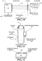
- FIG. 10 depicts system 10 deployed in this manner, with sensors 18 (designated with the prefix “FOPSS”) being inside a fuel tank and control 30 (designed “FOPSC”) being outside the tank.
- Control 30 may communicate with other systems AS of an aircraft in any appropriate manner.
- FIG. 11 shows a sample sensor 18 comprising two concentric tubes 106 and 110, top and bottom brackets 114 and 118, respectively, optical connector 102 with optical fiber 22, and terminal block 122 including electronics.
- FIG. 12 depicts a sample control 10 including optical connectors 102 for connection to aircraft systems AS and sensor 18.
Landscapes
- Physics & Mathematics (AREA)
- General Physics & Mathematics (AREA)
- Spectroscopy & Molecular Physics (AREA)
- Arrangements For Transmission Of Measured Signals (AREA)
Description
- This invention relates to sensing systems configured for reliable use in explosive (or other hazardous) environments and which provide eye protection should an optical fiber break. More particularly, the invention relates principally, but not necessarily exclusively, to systems in which free-running fuel sensors are powered optically on-board aircraft, with optical fibers both transmitting power to the sensors and receiving data signals from them.
- Various optically-powered sensor systems exist today.
U.S. Patent No. 4,820,916 to Patriquin discusses one such system, in which optical energy is transmitted along a bus for distribution to sensors of the system. Return pulses from the sensors likewise are transmitted on the bus to a system controller. Sensor-specific time delays are provided to produce a pre-determined, time-multiplexed sequence of the return pulses. -
U.S. Patent No. 4,963,729 to Spillman, et al. , discloses techniques for improving signal conditioning in optically-powered sensor systems. As with the system of the Patriquin patent, that of the Spillman patent transmits optical energy along a bus for distribution to sensors of the system. The bus also transmits return pulses from the sensors. - Yet another optically-powered sensor system is identified in
U.S. Patent No. 5,223,707 to Bjork . In some versions of the system, a controller may provide optical power to sensors and receive optical signals from the sensor locations on a single optical fiber. Alternatively, multiple optical fibers may be employed. Protocols are described which allow multiple sensors to communicate with a controller over a single optical fiber. -
U.S. Patent No. 7,965,948 to Bugash, et al. , finally, also addresses using a single fiber and systems for "receiving a light power signal via the single fiber optic ... and, in response to a pause in the received light power signal, transmitting a light data signal via the single optical fiber." The systems may be deployed in aircraft fuel tanks, with optical fibers used in lieu of electrical wires. It is also known a light-powered data acquisition and control system (as disclosed inUS 2008/0221825 A1 ) or a fiber-optic data-link interface (as disclosed inUS 5 528 409 ). - Absent from any of these patents is, for example, any method of detecting or predicting breakage of an optical fiber. Likewise absent, therefore, is any systematic reaction to fiber breakage, which could result in injury should a human eye be exposed to an unattenuated light signal emanating from a broken fiber. Further absent from patents of this sort is any electronic safety barrier circuitry designed to limit supplied power below accepted maximums for explosive environments. Power-optimizing schemes in which sensors act based on available power rather than directly on command of a controller also are omitted; consequently, no extra energy (for "worst-case" scenarios) need necessarily be sent.
- The present invention is defined in
independent claims 1 and 12 and provides optically-powered sensing systems supplying these advantageous features. An optical interface uses light to deliver energy in order to power typically remote, isolated circuits. This approach avoids need for any metallic wires, use of which can increase risk of explosion in certain hazardous environments. - Photovoltaic power converters are currently available. However, many require levels of optical radiation greater than appropriate for use in explosive environments or when the radiation might impinge on a human eye. The present invention, by contrast, does not. Instead, systems of the present invention employ voltage- and current-limiting circuitry to limit optical radiation present in at least the explosive environments. Additional hardware (or software) controls may adjust or de-energize the light power source under conditions suggesting such adjustment or de-energization is likely appropriate.
- The invention includes a system controller, a first optical fiber, and a first sensors. Typically multiple optical fibers and sensors are deployed, with a master microcontrol unit of the system controller separately controlling each sensor via a sensor control. Presently preferred is that a single optical fiber connect each sensor and its corresponding control--i.e. that a 1:1 correspondence exist between sensors and optical fibers--although such correspondence is not always necessary.
- Beneficially included within sensors useful with the present inventions are such components as light couplers, photovoltaic cells, power supply management circuitry, controllers, and transducers. Data light emitters also may be included within the sensors. The emitters may transfer data via the optical fibers to the corresponding sensor controls.
- Advantageously included with each sensor control may be a light power source, a light coupler, and a data light receiver. Also desirably comprising a sensor control may be circuitry providing automatic power reductions, normal and eye-protection light controls, and an electronic safety barrier. The safety barrier, when present, may function to ensure optical radiation levels do not exceed ignition levels of explosives extant in the environments of the systems, for example.
- Preferably independent circuits, the normal and eye-protection controls allow adjustment of light power levels or de-energization of light power sources. Power level adjustments may be made normally for efficiency or unusually for eye protection, for example. Additionally, either circuit may de-energize a light power source when appropriate to do so. Automatic power adjustments, including de-energization of the light power source, also may occur if a sensor does not transmit light data within a pre-determined (or determinable) period--as, for example, when an optical fiber has broken.
- As noted above, microcontrol units or other controllers may be included within the sensors themselves. Their presence allows sensors to self-manage available energy and hence be "free-running" -i.e. operable independent of the system controller. When electrical power is sufficient to do so, values may be acquired from transducers of the sensors and the acquired values transmitted by the data light emitter to the data light receiver via the light couplings and optical fibers.
- Although potentially useful for many purposes, systems of the present invention may have especial value in connection with aircraft fuel tanks. They may provide reliable service notwithstanding placement in explosive environments, may facilitate avoidance of eye injuries during certain repair or maintenance operations, and may supply reliability compatible with aircraft fuel tank applications. Integrity of transmitted data further may be enhanced through use of a digital encoding data bus.
- It thus is an optional, non-exclusive object of the present invention to provide improved optical sensing systems.
- It is a further optional, non-exclusive object of the present invention to provide sensing systems configured for reliable use in certain hazardous environments, including within fuel tanks of vehicles such as aircraft.
- It is also an optional, non-exclusive object of the present invention to provide sensing systems avoiding need for any metallic wires to transmit power or data through an explosive environment.
- It is, moreover, an optional, non-exclusive object of the present invention to provide sensing systems with automatic power reduction capabilities should, for example, breakage of an optical fiber be detected.
- The present invention to provides self-managing, "free-running" sensors that operate independent of a system controller.
- It is another optional, non-exclusive object of the present invention to provide optical sensing systems in which preferred versions have a 1:1 correspondence between sensors and optical fibers.
- Other objects, features, and advantages of the present invention will be apparent to those skilled in the appropriate field with reference to the remaining text and the drawings of this application.
-
-
FIG. 1 is a schematic diagram of an exemplary system consistent with the present invention. -
FIG. 2 is a schematic diagram of a sensor component of the system ofFIG. 1 . -
FIG. 3 is a schematic diagram of control and sensor components of the system ofFIG. 1 . -
FIG. 4 is a schematic diagram of an exemplary electronic safety barrier circuit for use as part of the system ofFIG. 1 . -
FIGS. 5-6 are block diagrams of an implementation of the safety barrier circuit ofFIG. 4 . -
FIG. 7 is a diagram illustrating exemplary timing of operation of an automatic power reduction circuit useful as part of the system ofFIG. 1 . -
FIG. 8 is a block diagram of interfaces of the automatic power reduction circuit ofFIG. 7 . -
FIG. 9 is another schematic diagram of the sensor component ofFIG. 2 . -
FIG. 10 is a functional diagram of the system ofFIG. 1 as used in a fuel tank. -
FIG. 11 is a partly-schematicized depiction of a sensor consistent withFIGS. 2 and9 . -
FIG. 12 is a partly-schematicized depiction of a controller consistent withFIG. 3 . - Illustrated in
FIG. 1 is anexemplary sensing system 10 of the present invention. Included as part ofsystem 10 may besystem controller 14, one ormore sensors 18, and one or moreoptical fibers 22.Optical fibers 22 function to transmit energy (power) and data between thesensors 18 and thesystem controller 14. Theoptical fibers 22 thus replace metal wires often used to transfer energy or information in the form of electricity. - As shown in
FIG. 1 ,system controller 14 may include bothmicrocontrol unit 26 and one or more sensor controls 30. In the preferred version ofsystem 10 depicted inFIG. 1 , a singleoptical fiber 22 couples eachsensor 18 to acorresponding sensor control 30. While presently preferred, such 1:1 correspondence amongfibers 22,sensors 18, and sensor controls 30 is not absolutely necessary, however. -
FIG. 2 shows asensor 18 together with its correspondingoptical fiber 22.Sensor 18 may comprise one or more transducers 34 (and associated interfaces) capable of measuring or otherwise sensing information of value tosystem 10. Transducers may be capacitive or resistive (e.g. capacitive probe level, capacitance index compensator, NTC or PTC thermistance, water level) or otherwise as desired.Sensor 18 additionally may include a controller such asmicrocontrol unit 38 configured to receive information fromtransducers 34 and process the information sufficiently for communication todata light emitter 42, which in cooperation withlight coupling 46 may emit light for conveyance throughoptical fiber 22. Also illustrated as part ofsensor 18 arephotovoltaic cell 50 and powersupply management circuitry 54, which may form part of thesmart system electronics 58 ofFIG. 3 . - Additionally detailed in
FIG. 3 are components ofsensor control 30. Such components may includelight coupling 58,data light receiver 62, and automaticpower reduction circuitry 66. Also preferably present insensor control 30 are eye-protectionlight control circuitry 70, normallight control circuitry 74,system controller electronics 78, andlight power source 82. Yet additionally,safety barrier circuitry 86 may be included as part ofsensor control 30. - One of multiple possible examples of
safety barrier circuitry 86 appears inFIG. 4 . As disclosed inU.S. Patent No. 5,144,517 to Wieth , whose entire contents are incorporated herein by this reference, barrier module "E" of that patent includes zener diodes functioning to shunt current paths should overvoltages or overcurrents arise. Resulting when necessary is opening of a fuse, thereby precluding current flow.FIGS. 5-6 provide block diagrams of similarexemplary circuitry 86, illustratingfuse 90, (preferably)parallel voltage suppressors 94 to limit overvoltages, andresister network 98 to limit overcurrents. Types and values of these elements may be selected by those skilled in the art so as to prevent emitted optical radiation from exceeding ignition levels of any explosive substance through which the radiation passes. - Eye-protection
light control circuitry 70 and normallight control circuitry 74, preferably independent circuits, may be interposed in series betweenlight power source 82 and ground.Circuitry light power source 82, hence allowing light emission. Advantageously, normallight control circuitry 74 is controlled bysystem controller electronics 78, which may energize or de-energizelight power source 82, or adjust its power level for power efficiency optimization (or otherwise). Power levels oflight power source 82 may be adjusted using refresh times of measurements and achieved via pulse width modulation (PWM) or linear regulation, for example. Preferably, average power during a measurement cycle may be used to define a power level. Evaluating power levels as a function of refresh times may beneficially allow a health monitoring of optical paths, permitting preventative maintenance to be scheduled before occurrence of any failure which might ground an aircraft for unscheduled maintenance. - Eye-protection
light control circuitry 70, by contrast, beneficially is controlled by automatic power reduction circuitry 66 (seeFIG. 8 ) and may de-energize light power source 82 (or, in some versions, adjust its power level) when necessary. As shown inFIG. 7 , automaticpower reduction circuitry 66 preferably de-energizeslight power source 82 if no data transmission from datalight emitter 42 is received during a selected interval (Twait). The interval may be initialized by light reception or by the release of power. -
FIG. 9 illustrates, among other things, inclusion ofmicrocontrol unit 38 insensor 18. Using information from powersupply management circuitry 54,microcontrol unit 38 acquires information fromtransducers 34 when available electrical power is sufficient to do so. In at least thissense sensor 18 thus is free-running, withmicrocontrol unit 38 acquiring information fromtransducers 34 as fast as possible given the electrical power then-currently available. Or, stated differently,sensor 18 harvests energy and performs when sufficient energy is available. Hence,sensor 18 is not synchronized withsystem controller 14; no extra energy need ever be sent tosensor 18, and essentially no energy is wasted. After acquiring information,microcontrol unit 38 may transmit, using a digital encoding protocol, the measurements (or other information) through datalight emitter 42. Use of the digital bus allows for integrity data checks to occur, with such possible checks including, but not being limited to, parity bits, checksums, or cyclic redundancy checks depending on importance of the data. Additionally, need for maintenance may be predicted if power increases are necessary to obtain a desired refresh rate. - As noted earlier,
system 10 is especially useful as sensors of fuel-related information in aircraft fuel tanks.FIG. 10 depictssystem 10 deployed in this manner, with sensors 18 (designated with the prefix "FOPSS") being inside a fuel tank and control 30 (designed "FOPSC") being outside the tank.Control 30 may communicate with other systems AS of an aircraft in any appropriate manner. Becauseoptical fibers 22 extend betweenconnectors 102 ofcontrol 30 andsensors 18, no metal wires needconnect control 30 andsensors 18.FIG. 11 shows asample sensor 18 comprising two concentric tubes 106 and 110, top andbottom brackets optical connector 102 withoptical fiber 22, andterminal block 122 including electronics.FIG. 12 depicts asample control 10 includingoptical connectors 102 for connection to aircraft systems AS andsensor 18. - The foregoing is provided for purposes of illustrating, explaining, and describing embodiments of the present invention. Modifications and adaptations to these embodiments will be apparent to those skilled in the art.
Claims (16)
- An optical sensing system (10) for an aircraft having a fuel tank comprising:a. a system controller (14);b. a first sensor (18) adapted for being positioned within an aircraft fuel tank; andc. a first optical fiber (22) adapted for being positioned at least partially outside the aircraft fuel tank; andin which(i) the system controller (14) comprises(A) means for transmitting optical energy to the first sensor (18) via the first optical fiber (22) and;(B) means for receiving optical data from the first sensor (18) via the first optical fiber (22) and(ii) the first sensor (18) comprises;(A) means adapted for being positioned within the fuel tank of the aircraft for converting received optical energy to electrical energy; and(B) means adapted for being positioned within the fuel tank of the aircraft for transmitting optical data as available electrical energy permitscharacterized in that the first sensor (18) is a self-managing, free-running sensor that operates independently of the system controller (14) such that the sensor is not synchronised with the system controller.
- An optical sensing system (10) according to claim 1 in which the system controller (14) further comprises means for limiting optical energy transmitted to the first sensor (18).
- An optical sensing system (10) according to claim 2 in which the means for limiting optical energy transmitted to the first sensor (18) operates as a function of whether the first sensor (18) has transmitted optical data during a predetermined or determinable period of time.
- An optical sensing system (10) according to claim 2 in which (a) the means for transmitting optical energy to the first sensor (18) comprises a light power source (82) and (b) the means for limiting optical energy transmitted to the first sensor (18) operates as a function of whether electrical power available to the light power source (82) exceeds a predetermined or determinable value.
- An optical sensing system (10) according to claim 1 in which (a) the first sensor (18) further comprises a controller (38) and (b) the means for transmitting optical data comprises a digital data encoding protocol.
- An optical sensing system (10) according to claim 1 in which the first sensor (18) further comprises means for sensing a characteristic associated with the aircraft fuel tank.
- An optical sensing system (10) according to claim 1 further comprising a second sensor (18) and in which the at least one optical fiber (22) comprises first and second optical fibers, (a) the first optical fiber conveying optical energy from the system controller (14) to the first sensor (18) and optical data from the first sensor (18) to the system controller (14) and (b) the second optical fiber conveying optical energy from the system controller (14) to the second sensor (18) and optical data from the second sensor (18) to the system controller (14).
- An optical sensing system (10) according to claim 1, wherein:
the system controller (14) is adapted for being positioned at least partially outside an aircraft fuel tank and configured to communicate with at least one other system of an aircraft. - An optical sensing system (10) according to claim 8 wherein the optical sensing system (10) further comprises:a second sensor (18) adapted for being positioned within an aircraft fuel tank of the aircraft; andat least a second optical fiber (22) adapted for being positioned at least partially outside an aircraft fuel tank; andin which(i) the system controller (14)_comprises:(A) means for transmitting optical energy to the first sensor (18) via only the first optical fiber (22) and to the second sensor (18) via only the second optical fiber (22),(B) means for receiving optical data from the first sensor (18) via only the first optical fiber (22) and from the second sensor (18) via only the second optical fiber (22), and(ii) the second sensor (18) comprises(A) means adapted for being positioned within the fuel tank of the aircraft for converting received optical energy to electrical energy,(B) means adapted for being positioned within the fuel tank of the aircraft for transmitting optical data as available electrical energy permits, and (C) a controller (38) wherein the second sensor (18) is a self-managing sensor that operates independently of the system controller (14) such that the sensor is not synchronised with the system controller.
- An optical sensing system (10) according to claim 9 wherein the system controller (14) comprises means for limiting optical energy transmitted to at least one of the first and second sensors (18).
- An optical sensing system (10) according to claim 8 or 9 wherein each of the first and second sensors (18) comprises a controller (38).
- A sensing method comprising:a. transmitting optical energy from a system controller (14) to a sensor (18) via an optical fiber (22), the sensor (18) being positioned within an aircraft fuel tank and the optical fiber (22) being positioned at least partially outside the aircraft fuel tank, the sensor (18) being a self-managing sensor that operates independently of the system controller (14) such that the sensor is not synchronised with the system controller;b. at the sensor (18), converting the optical energy to electrical energy;c. when sufficient electrical energy exists at the sensor to do so, sensing information relating to the environment of the sensor; andd. when sufficient electrical energy exists at the sensor (18) to do so, transmitting the sensed information to the system controller via the optical fiber (22).
- A sensing method according to claim 12 further comprising reducing the amount of optical energy transmitted to the sensor (18) when the optical fiber (22) is broken, or reducing the amount of optical energy transmitted to the sensor (18) to less than an amount that would ignite flammable fluid present in the environment of the sensor (18).
- An optical sensing system (10) according to claim 5 in which the digital data information comprises integrity check data.
- An optical sensing system(10) according to claim 1 further comprising :(a) a light power source (82) and(b) means for adjusting a power level of the light power source (82) for improved operational efficiency.
- An optical sensing system according to claim 6 wherein said sensing means comprises a NTC or PTC thermistance.
Applications Claiming Priority (2)
| Application Number | Priority Date | Filing Date | Title |
|---|---|---|---|
| US201261739168P | 2012-12-19 | 2012-12-19 | |
| PCT/IB2013/061148 WO2014097215A1 (en) | 2012-12-19 | 2013-12-19 | Optically-powered sensor systems, suitable for deployment on-board aircraft |
Publications (2)
| Publication Number | Publication Date |
|---|---|
| EP2936072A1 EP2936072A1 (en) | 2015-10-28 |
| EP2936072B1 true EP2936072B1 (en) | 2019-02-20 |
Family
ID=50071659
Family Applications (1)
| Application Number | Title | Priority Date | Filing Date |
|---|---|---|---|
| EP13828940.0A Active EP2936072B1 (en) | 2012-12-19 | 2013-12-19 | Optically-powered sensor systems, suitable for deployment on-board aircraft |
Country Status (4)
| Country | Link |
|---|---|
| US (1) | US9671279B2 (en) |
| EP (1) | EP2936072B1 (en) |
| CA (1) | CA2893348C (en) |
| WO (1) | WO2014097215A1 (en) |
Families Citing this family (9)
| Publication number | Priority date | Publication date | Assignee | Title |
|---|---|---|---|---|
| DE102014213849A1 (en) * | 2014-07-16 | 2016-01-21 | Siemens Aktiengesellschaft | Method for transmitting a signal, signal transmission device and measuring device |
| US10094982B2 (en) * | 2015-03-11 | 2018-10-09 | Parker-Hannifin Corporation | Passive optical circuit breaker having plural optical waveguide portions with different transmissivities |
| US10107774B2 (en) * | 2016-03-18 | 2018-10-23 | Simonds Precision Products, Inc. | Optically interfaced fuel characteristic sensor |
| US9906300B2 (en) * | 2016-05-20 | 2018-02-27 | Rosemount Aerospace Inc. | Optically powered transducer module |
| US10435170B2 (en) * | 2016-12-08 | 2019-10-08 | The Boeing Company | Systems and methods for installation of sensors for fuel quantity indicating systems |
| US10313026B2 (en) | 2017-06-27 | 2019-06-04 | Rolls-Royce North American Technologies, Inc. | Power and communications over fiber optic cabling |
| US10451446B2 (en) | 2018-01-19 | 2019-10-22 | Rosemount Aerospace Inc. | System for interfacing with an optically-powered sensor |
| US11167859B2 (en) | 2018-12-12 | 2021-11-09 | Parker-Hannifin Corporation | Remote fuel system sensor with wireless energy harvesting |
| CN112367118A (en) * | 2020-10-12 | 2021-02-12 | 岭东核电有限公司 | Information transmission method, device and system for nuclear power plant |
Citations (1)
| Publication number | Priority date | Publication date | Assignee | Title |
|---|---|---|---|---|
| US4641025A (en) * | 1984-12-05 | 1987-02-03 | The Boeing Company | System for determining the position of the boundary between substances having different refractive indices |
Family Cites Families (14)
| Publication number | Priority date | Publication date | Assignee | Title |
|---|---|---|---|---|
| US4820916A (en) | 1987-05-05 | 1989-04-11 | Simmonds Precision Products | Optically powered sensor system |
| US4963729A (en) | 1989-03-03 | 1990-10-16 | Simmonds Precision Products, Inc. | Optically powered sensor system with improved signal conditioning |
| US5144517A (en) | 1989-10-20 | 1992-09-01 | Pepperl + Fuchs, Inc. | Intrinsically safe barrier device |
| US5223707A (en) | 1992-06-01 | 1993-06-29 | Honeywell Inc. | Optically powered remote sensor apparatus with synchronizing means |
| US5528409A (en) * | 1994-10-13 | 1996-06-18 | Nt International, Inc. | Fiber-optic interface system |
| US6356809B1 (en) | 1999-06-11 | 2002-03-12 | Cbi Systems Corporation | Electro-statically shielded processing module |
| JP2002182253A (en) * | 2000-12-12 | 2002-06-26 | Sumitomo Electric Ind Ltd | Light source safety device, Raman amplifier and optical transmission system |
| US20040021100A1 (en) * | 2002-04-12 | 2004-02-05 | Mikhail Gouzman | Fiber-optic sensor for measuring level of fluid |
| US7710567B1 (en) * | 2006-03-14 | 2010-05-04 | Strube, Inc. | Systems and methods for determining level and/or type of a fluid |
| US7511259B2 (en) | 2006-04-24 | 2009-03-31 | Northrop Grumman Corporation | Smart integrated distributed light-powered process control system |
| US7965948B1 (en) | 2008-01-04 | 2011-06-21 | Simmonds Precision Products, Inc. | Power and data transmitted over a single optical fiber |
| JP2010015781A (en) * | 2008-07-02 | 2010-01-21 | Sharp Corp | Light source device and lighting device |
| GB2465493B (en) * | 2008-11-25 | 2011-07-27 | Stanley Electric Co Ltd | Liquid-cooled LED lighting device |
| US10429228B2 (en) * | 2013-05-13 | 2019-10-01 | The Boeing Company | Fuel level measurement using in-tank measuring system |
-
2013
- 2013-12-19 US US14/133,823 patent/US9671279B2/en active Active
- 2013-12-19 CA CA2893348A patent/CA2893348C/en active Active
- 2013-12-19 WO PCT/IB2013/061148 patent/WO2014097215A1/en not_active Ceased
- 2013-12-19 EP EP13828940.0A patent/EP2936072B1/en active Active
Patent Citations (1)
| Publication number | Priority date | Publication date | Assignee | Title |
|---|---|---|---|---|
| US4641025A (en) * | 1984-12-05 | 1987-02-03 | The Boeing Company | System for determining the position of the boundary between substances having different refractive indices |
Also Published As
| Publication number | Publication date |
|---|---|
| EP2936072A1 (en) | 2015-10-28 |
| US20140166852A1 (en) | 2014-06-19 |
| CA2893348A1 (en) | 2014-06-26 |
| WO2014097215A1 (en) | 2014-06-26 |
| US9671279B2 (en) | 2017-06-06 |
| CA2893348C (en) | 2021-10-19 |
Similar Documents
| Publication | Publication Date | Title |
|---|---|---|
| CA2893348C (en) | Optically-powered sensor systems principally for deployment on-board aircraft | |
| US9793991B2 (en) | Optically interfaced remote data concentrator | |
| EP2481267B1 (en) | A method for controlling the operation of an electronic converter, and a corresponding electronic converter, lighting system and software product | |
| US20080180226A1 (en) | Intrinsically safe galvanically isolated barrier device and method thereof | |
| US7965948B1 (en) | Power and data transmitted over a single optical fiber | |
| KR20060030894A (en) | Optical transceiver module with power integrated circuit | |
| EP1649617A4 (en) | Optoelectronic transceiver having dual access to onboard diagnostics | |
| US20100214091A1 (en) | Verfahren zum betreiben eines feldgerates, sowie kommunikationseinheit und feldgerat | |
| US20180307191A1 (en) | Modular field device having a display/operating device containing a radio module and an internal power supply | |
| US20110011293A1 (en) | Networked electronic ordnance system | |
| WO2007048005A2 (en) | Optical interface for communicating optical transceiver status information | |
| WO2014001304A1 (en) | Heated floor panel for an aircraft and aircraft having a heated floor panel | |
| US20060236189A1 (en) | Distributed control apparatus | |
| CN103196482B (en) | Method and corresponding transmitter for monitoring transmitter | |
| US20140104072A1 (en) | Light signal device and method for ascertaining the degree of soiling of a shutter disk for a signal generator | |
| EP3505876B1 (en) | Systems and methods for liquid level detection | |
| WO2007035290A2 (en) | Optical transceiver with custom logging mechanism | |
| US5805052A (en) | Cable system for signal transmission | |
| CN102331710A (en) | The control panel that is used for aircraft | |
| US8237137B2 (en) | Photoelectronic sensor system having auto-adjustment function | |
| EP2952008A1 (en) | Method of data communication with multiple liquid level detection sensors connected to a central processing unit, and liquid level detection system | |
| CN107294762A (en) | Telecommunication system for programmable logic controller (PLC) | |
| US8637827B2 (en) | Radiation monitor and method for checking operation of the same | |
| US7696468B2 (en) | Device for detecting objects in a monitored area | |
| US20090216511A1 (en) | Sensor Simulator |
Legal Events
| Date | Code | Title | Description |
|---|---|---|---|
| PUAI | Public reference made under article 153(3) epc to a published international application that has entered the european phase |
Free format text: ORIGINAL CODE: 0009012 |
|
| 17P | Request for examination filed |
Effective date: 20150714 |
|
| AK | Designated contracting states |
Kind code of ref document: A1 Designated state(s): AL AT BE BG CH CY CZ DE DK EE ES FI FR GB GR HR HU IE IS IT LI LT LU LV MC MK MT NL NO PL PT RO RS SE SI SK SM TR |
|
| AX | Request for extension of the european patent |
Extension state: BA ME |
|
| DAX | Request for extension of the european patent (deleted) | ||
| STAA | Information on the status of an ep patent application or granted ep patent |
Free format text: STATUS: EXAMINATION IS IN PROGRESS |
|
| 17Q | First examination report despatched |
Effective date: 20161219 |
|
| GRAP | Despatch of communication of intention to grant a patent |
Free format text: ORIGINAL CODE: EPIDOSNIGR1 |
|
| STAA | Information on the status of an ep patent application or granted ep patent |
Free format text: STATUS: GRANT OF PATENT IS INTENDED |
|
| INTG | Intention to grant announced |
Effective date: 20180424 |
|
| GRAJ | Information related to disapproval of communication of intention to grant by the applicant or resumption of examination proceedings by the epo deleted |
Free format text: ORIGINAL CODE: EPIDOSDIGR1 |
|
| STAA | Information on the status of an ep patent application or granted ep patent |
Free format text: STATUS: EXAMINATION IS IN PROGRESS |
|
| GRAP | Despatch of communication of intention to grant a patent |
Free format text: ORIGINAL CODE: EPIDOSNIGR1 |
|
| STAA | Information on the status of an ep patent application or granted ep patent |
Free format text: STATUS: GRANT OF PATENT IS INTENDED |
|
| INTC | Intention to grant announced (deleted) | ||
| INTG | Intention to grant announced |
Effective date: 20180911 |
|
| GRAS | Grant fee paid |
Free format text: ORIGINAL CODE: EPIDOSNIGR3 |
|
| GRAA | (expected) grant |
Free format text: ORIGINAL CODE: 0009210 |
|
| STAA | Information on the status of an ep patent application or granted ep patent |
Free format text: STATUS: THE PATENT HAS BEEN GRANTED |
|
| AK | Designated contracting states |
Kind code of ref document: B1 Designated state(s): AL AT BE BG CH CY CZ DE DK EE ES FI FR GB GR HR HU IE IS IT LI LT LU LV MC MK MT NL NO PL PT RO RS SE SI SK SM TR |
|
| REG | Reference to a national code |
Ref country code: GB Ref legal event code: FG4D |
|
| REG | Reference to a national code |
Ref country code: CH Ref legal event code: EP |
|
| REG | Reference to a national code |
Ref country code: DE Ref legal event code: R096 Ref document number: 602013051152 Country of ref document: DE |
|
| REG | Reference to a national code |
Ref country code: AT Ref legal event code: REF Ref document number: 1098796 Country of ref document: AT Kind code of ref document: T Effective date: 20190315 |
|
| REG | Reference to a national code |
Ref country code: IE Ref legal event code: FG4D |
|
| REG | Reference to a national code |
Ref country code: NL Ref legal event code: MP Effective date: 20190220 |
|
| REG | Reference to a national code |
Ref country code: LT Ref legal event code: MG4D |
|
| PG25 | Lapsed in a contracting state [announced via postgrant information from national office to epo] |
Ref country code: FI Free format text: LAPSE BECAUSE OF FAILURE TO SUBMIT A TRANSLATION OF THE DESCRIPTION OR TO PAY THE FEE WITHIN THE PRESCRIBED TIME-LIMIT Effective date: 20190220 Ref country code: NL Free format text: LAPSE BECAUSE OF FAILURE TO SUBMIT A TRANSLATION OF THE DESCRIPTION OR TO PAY THE FEE WITHIN THE PRESCRIBED TIME-LIMIT Effective date: 20190220 Ref country code: SE Free format text: LAPSE BECAUSE OF FAILURE TO SUBMIT A TRANSLATION OF THE DESCRIPTION OR TO PAY THE FEE WITHIN THE PRESCRIBED TIME-LIMIT Effective date: 20190220 Ref country code: LT Free format text: LAPSE BECAUSE OF FAILURE TO SUBMIT A TRANSLATION OF THE DESCRIPTION OR TO PAY THE FEE WITHIN THE PRESCRIBED TIME-LIMIT Effective date: 20190220 Ref country code: NO Free format text: LAPSE BECAUSE OF FAILURE TO SUBMIT A TRANSLATION OF THE DESCRIPTION OR TO PAY THE FEE WITHIN THE PRESCRIBED TIME-LIMIT Effective date: 20190520 Ref country code: PT Free format text: LAPSE BECAUSE OF FAILURE TO SUBMIT A TRANSLATION OF THE DESCRIPTION OR TO PAY THE FEE WITHIN THE PRESCRIBED TIME-LIMIT Effective date: 20190620 |
|
| PG25 | Lapsed in a contracting state [announced via postgrant information from national office to epo] |
Ref country code: HR Free format text: LAPSE BECAUSE OF FAILURE TO SUBMIT A TRANSLATION OF THE DESCRIPTION OR TO PAY THE FEE WITHIN THE PRESCRIBED TIME-LIMIT Effective date: 20190220 Ref country code: RS Free format text: LAPSE BECAUSE OF FAILURE TO SUBMIT A TRANSLATION OF THE DESCRIPTION OR TO PAY THE FEE WITHIN THE PRESCRIBED TIME-LIMIT Effective date: 20190220 Ref country code: GR Free format text: LAPSE BECAUSE OF FAILURE TO SUBMIT A TRANSLATION OF THE DESCRIPTION OR TO PAY THE FEE WITHIN THE PRESCRIBED TIME-LIMIT Effective date: 20190521 Ref country code: IS Free format text: LAPSE BECAUSE OF FAILURE TO SUBMIT A TRANSLATION OF THE DESCRIPTION OR TO PAY THE FEE WITHIN THE PRESCRIBED TIME-LIMIT Effective date: 20190620 Ref country code: LV Free format text: LAPSE BECAUSE OF FAILURE TO SUBMIT A TRANSLATION OF THE DESCRIPTION OR TO PAY THE FEE WITHIN THE PRESCRIBED TIME-LIMIT Effective date: 20190220 Ref country code: BG Free format text: LAPSE BECAUSE OF FAILURE TO SUBMIT A TRANSLATION OF THE DESCRIPTION OR TO PAY THE FEE WITHIN THE PRESCRIBED TIME-LIMIT Effective date: 20190520 |
|
| REG | Reference to a national code |
Ref country code: AT Ref legal event code: MK05 Ref document number: 1098796 Country of ref document: AT Kind code of ref document: T Effective date: 20190220 |
|
| PG25 | Lapsed in a contracting state [announced via postgrant information from national office to epo] |
Ref country code: EE Free format text: LAPSE BECAUSE OF FAILURE TO SUBMIT A TRANSLATION OF THE DESCRIPTION OR TO PAY THE FEE WITHIN THE PRESCRIBED TIME-LIMIT Effective date: 20190220 Ref country code: SK Free format text: LAPSE BECAUSE OF FAILURE TO SUBMIT A TRANSLATION OF THE DESCRIPTION OR TO PAY THE FEE WITHIN THE PRESCRIBED TIME-LIMIT Effective date: 20190220 Ref country code: RO Free format text: LAPSE BECAUSE OF FAILURE TO SUBMIT A TRANSLATION OF THE DESCRIPTION OR TO PAY THE FEE WITHIN THE PRESCRIBED TIME-LIMIT Effective date: 20190220 Ref country code: CZ Free format text: LAPSE BECAUSE OF FAILURE TO SUBMIT A TRANSLATION OF THE DESCRIPTION OR TO PAY THE FEE WITHIN THE PRESCRIBED TIME-LIMIT Effective date: 20190220 Ref country code: ES Free format text: LAPSE BECAUSE OF FAILURE TO SUBMIT A TRANSLATION OF THE DESCRIPTION OR TO PAY THE FEE WITHIN THE PRESCRIBED TIME-LIMIT Effective date: 20190220 Ref country code: AL Free format text: LAPSE BECAUSE OF FAILURE TO SUBMIT A TRANSLATION OF THE DESCRIPTION OR TO PAY THE FEE WITHIN THE PRESCRIBED TIME-LIMIT Effective date: 20190220 Ref country code: IT Free format text: LAPSE BECAUSE OF FAILURE TO SUBMIT A TRANSLATION OF THE DESCRIPTION OR TO PAY THE FEE WITHIN THE PRESCRIBED TIME-LIMIT Effective date: 20190220 Ref country code: DK Free format text: LAPSE BECAUSE OF FAILURE TO SUBMIT A TRANSLATION OF THE DESCRIPTION OR TO PAY THE FEE WITHIN THE PRESCRIBED TIME-LIMIT Effective date: 20190220 |
|
| REG | Reference to a national code |
Ref country code: DE Ref legal event code: R097 Ref document number: 602013051152 Country of ref document: DE |
|
| PG25 | Lapsed in a contracting state [announced via postgrant information from national office to epo] |
Ref country code: PL Free format text: LAPSE BECAUSE OF FAILURE TO SUBMIT A TRANSLATION OF THE DESCRIPTION OR TO PAY THE FEE WITHIN THE PRESCRIBED TIME-LIMIT Effective date: 20190220 Ref country code: SM Free format text: LAPSE BECAUSE OF FAILURE TO SUBMIT A TRANSLATION OF THE DESCRIPTION OR TO PAY THE FEE WITHIN THE PRESCRIBED TIME-LIMIT Effective date: 20190220 |
|
| PLBE | No opposition filed within time limit |
Free format text: ORIGINAL CODE: 0009261 |
|
| STAA | Information on the status of an ep patent application or granted ep patent |
Free format text: STATUS: NO OPPOSITION FILED WITHIN TIME LIMIT |
|
| PG25 | Lapsed in a contracting state [announced via postgrant information from national office to epo] |
Ref country code: AT Free format text: LAPSE BECAUSE OF FAILURE TO SUBMIT A TRANSLATION OF THE DESCRIPTION OR TO PAY THE FEE WITHIN THE PRESCRIBED TIME-LIMIT Effective date: 20190220 |
|
| 26N | No opposition filed |
Effective date: 20191121 |
|
| PG25 | Lapsed in a contracting state [announced via postgrant information from national office to epo] |
Ref country code: SI Free format text: LAPSE BECAUSE OF FAILURE TO SUBMIT A TRANSLATION OF THE DESCRIPTION OR TO PAY THE FEE WITHIN THE PRESCRIBED TIME-LIMIT Effective date: 20190220 |
|
| PG25 | Lapsed in a contracting state [announced via postgrant information from national office to epo] |
Ref country code: TR Free format text: LAPSE BECAUSE OF FAILURE TO SUBMIT A TRANSLATION OF THE DESCRIPTION OR TO PAY THE FEE WITHIN THE PRESCRIBED TIME-LIMIT Effective date: 20190220 |
|
| REG | Reference to a national code |
Ref country code: CH Ref legal event code: PL |
|
| REG | Reference to a national code |
Ref country code: BE Ref legal event code: MM Effective date: 20191231 |
|
| PG25 | Lapsed in a contracting state [announced via postgrant information from national office to epo] |
Ref country code: MC Free format text: LAPSE BECAUSE OF FAILURE TO SUBMIT A TRANSLATION OF THE DESCRIPTION OR TO PAY THE FEE WITHIN THE PRESCRIBED TIME-LIMIT Effective date: 20190220 |
|
| GBPC | Gb: european patent ceased through non-payment of renewal fee |
Effective date: 20191219 |
|
| PG25 | Lapsed in a contracting state [announced via postgrant information from national office to epo] |
Ref country code: LU Free format text: LAPSE BECAUSE OF NON-PAYMENT OF DUE FEES Effective date: 20191219 Ref country code: GB Free format text: LAPSE BECAUSE OF NON-PAYMENT OF DUE FEES Effective date: 20191219 Ref country code: IE Free format text: LAPSE BECAUSE OF NON-PAYMENT OF DUE FEES Effective date: 20191219 |
|
| PG25 | Lapsed in a contracting state [announced via postgrant information from national office to epo] |
Ref country code: LI Free format text: LAPSE BECAUSE OF NON-PAYMENT OF DUE FEES Effective date: 20191231 Ref country code: BE Free format text: LAPSE BECAUSE OF NON-PAYMENT OF DUE FEES Effective date: 20191231 Ref country code: CH Free format text: LAPSE BECAUSE OF NON-PAYMENT OF DUE FEES Effective date: 20191231 |
|
| REG | Reference to a national code |
Ref country code: DE Ref legal event code: R081 Ref document number: 602013051152 Country of ref document: DE Owner name: SAFRAN AEROSYSTEMS, FR Free format text: FORMER OWNER: ZODIAC AEROTECHNICS, PLAISIR, FR Ref country code: DE Ref legal event code: R081 Ref document number: 602013051152 Country of ref document: DE Owner name: SAFRAN AEROTECHNICS S.A.S., FR Free format text: FORMER OWNER: ZODIAC AEROTECHNICS, PLAISIR, FR |
|
| PG25 | Lapsed in a contracting state [announced via postgrant information from national office to epo] |
Ref country code: CY Free format text: LAPSE BECAUSE OF FAILURE TO SUBMIT A TRANSLATION OF THE DESCRIPTION OR TO PAY THE FEE WITHIN THE PRESCRIBED TIME-LIMIT Effective date: 20190220 |
|
| PG25 | Lapsed in a contracting state [announced via postgrant information from national office to epo] |
Ref country code: HU Free format text: LAPSE BECAUSE OF FAILURE TO SUBMIT A TRANSLATION OF THE DESCRIPTION OR TO PAY THE FEE WITHIN THE PRESCRIBED TIME-LIMIT; INVALID AB INITIO Effective date: 20131219 Ref country code: MT Free format text: LAPSE BECAUSE OF FAILURE TO SUBMIT A TRANSLATION OF THE DESCRIPTION OR TO PAY THE FEE WITHIN THE PRESCRIBED TIME-LIMIT Effective date: 20190220 |
|
| PG25 | Lapsed in a contracting state [announced via postgrant information from national office to epo] |
Ref country code: MK Free format text: LAPSE BECAUSE OF FAILURE TO SUBMIT A TRANSLATION OF THE DESCRIPTION OR TO PAY THE FEE WITHIN THE PRESCRIBED TIME-LIMIT Effective date: 20190220 |
|
| REG | Reference to a national code |
Ref country code: DE Ref legal event code: R081 Ref document number: 602013051152 Country of ref document: DE Owner name: SAFRAN AEROSYSTEMS, FR Free format text: FORMER OWNER: SAFRAN AEROTECHNICS S.A.S., PLAISIR, FR |
|
| PGFP | Annual fee paid to national office [announced via postgrant information from national office to epo] |
Ref country code: FR Payment date: 20251222 Year of fee payment: 13 |
|
| PGFP | Annual fee paid to national office [announced via postgrant information from national office to epo] |
Ref country code: DE Payment date: 20251222 Year of fee payment: 13 |