EP2935200B1 - Separation method for dinitrotoluene and mixed acid in a toluene to dinitrotoluene process - Google Patents
Separation method for dinitrotoluene and mixed acid in a toluene to dinitrotoluene process Download PDFInfo
- Publication number
- EP2935200B1 EP2935200B1 EP13802958.2A EP13802958A EP2935200B1 EP 2935200 B1 EP2935200 B1 EP 2935200B1 EP 13802958 A EP13802958 A EP 13802958A EP 2935200 B1 EP2935200 B1 EP 2935200B1
- Authority
- EP
- European Patent Office
- Prior art keywords
- stream
- reactor
- range
- separation method
- coalescer
- Prior art date
- Legal status (The legal status is an assumption and is not a legal conclusion. Google has not performed a legal analysis and makes no representation as to the accuracy of the status listed.)
- Active
Links
Images


Classifications
-
- C—CHEMISTRY; METALLURGY
- C07—ORGANIC CHEMISTRY
- C07C—ACYCLIC OR CARBOCYCLIC COMPOUNDS
- C07C201/00—Preparation of esters of nitric or nitrous acid or of compounds containing nitro or nitroso groups bound to a carbon skeleton
- C07C201/06—Preparation of nitro compounds
- C07C201/08—Preparation of nitro compounds by substitution of hydrogen atoms by nitro groups
-
- B—PERFORMING OPERATIONS; TRANSPORTING
- B01—PHYSICAL OR CHEMICAL PROCESSES OR APPARATUS IN GENERAL
- B01D—SEPARATION
- B01D17/00—Separation of liquids, not provided for elsewhere, e.g. by thermal diffusion
- B01D17/02—Separation of non-miscible liquids
- B01D17/0217—Separation of non-miscible liquids by centrifugal force
-
- C—CHEMISTRY; METALLURGY
- C07—ORGANIC CHEMISTRY
- C07C—ACYCLIC OR CARBOCYCLIC COMPOUNDS
- C07C201/00—Preparation of esters of nitric or nitrous acid or of compounds containing nitro or nitroso groups bound to a carbon skeleton
- C07C201/06—Preparation of nitro compounds
- C07C201/16—Separation; Purification; Stabilisation; Use of additives
Definitions
- the invention relates to a separation method in a toluene to dinitrotoluene process by separating an organic phase from a mixed acid phase by the use of a coalescer.
- the organic phase comprises mono- and/or dinitrotoluene.
- the mixed acid phase comprises sulfuric acid, nitric acid, nitrous acid and nitrogene oxides gas e.g. resulting from the decomposition of nitrous acid.
- nitration of toluene to dinitrotoluene is well known.
- a toluene to dinitrotoluene process consists of two steps. In a first step toluene reacts with nitric acid in a nitration reactor to mononitrotoluene as an organic phase and in a second step the mononitrotoluene reacts with nitric acid and sulfuric acid in a nitration reactor to dinitrotoluene as an organic phase.
- the effluent of each of the reactors is a mixture of an organic phase and a mixed acid phase.
- the organic phase can be separated from the acid phase.
- a dynamic separator is used in US7851661 B2 for the separation of a reaction product into an organic phase comprising mononitrotoluene and an aqueous phase comprising sulfuric acid.
- the dynamic separation occurs by centrifugal force or static settlement separation by gravity.
- a problem of dynamic separation is that dynamic separators cannot completely separate organics phase from mixed acid phase due to limitation in the technical structure by which a separator is equipped.
- the limitation of dynamic separator technical structure is that two phases interphase is controlled in the equipment by so-called regular rings which function similar to a wear in a static settler at heavy and light phases discharger sides, and the regular ring is a kind of fixed device in the equipment which can not be controlled during normal operation.
- the only way of adjustment of the equipment is to shut down and disassemble the dynamic separator and change the regular rings into a rings of different dimensions. A shut down of the dynamic separator decreases the efficiency of the separation process.
- a reaction possibility for the by-product of black acid components can be shown as follows: NO + NO 2 + 2H 2 SO 4 ⁇ 2NOHSO 4 + H 2 O C 7 H 8 + 2NOHSO 4 + 3H 2 SO 4 ⁇ (C 7 H 8 ) * (NOHSO 4 ) 2 * (H 2 SO 4 ) 3
- the black acid component can occur when residence times in a mononitrotoluene reactor is too short or in case there is a lack of nitric acid.
- An advantage of the present invention is a reduction of the internal circulation of about 10% which results in a reduction of residence time in the mononitrotoluene reactor of about 10%. The benefits are less safety risks and an improved and efficient control of the toluene concentration. By this the bottleneck of the production plant operation is removed.
- a reaction product is separated into an organic phase containing mononitrotoluene and a first spent acid phase by a phase separator. Also in US5902910A an organic phase containing dinitrotoluene is separated from a second spent acid phase by a phase separator.
- phase separator is mentioned after certain stages of production but no more details regarding the kind of separator and/or the basic principle of the separation method and/or the separation process are given.
- phase separators A general disadvantage of phase separators is plugging which often occurs after a certain operation time. Reasons for plugging can be that corroded particles get stuck in devices and/or fouling products block the devices. As a result of plugging the production process has to be shutdown and phase separators to be disassembled and cleaned. A shut down of a separator decreases the efficiency of the separation process.
- a separation method in a toluene to dinitrotoluene process said method with a first process step comprising feeding a toluene comprising first stream and a nitric acid comprising second stream into a first reactor, reacting of the toluene comprising first stream and the nitric acid comprising second stream within the first reactor to a first reaction mixture, said first reaction mixture comprising a first liquid/liquid mixed phase of an acid phase and an organic phase comprising mononitrotoluene, feeding the first reaction mixture into a first separation device, separating the first reaction mixture within the first separation device into a first forward stream having a flow direction to a second process step and a first backward stream having a flow direction back to the first reactor, said method having a second process step comprising feeding the first forward stream into a second reactor, feeding a nitric acid comprising third stream and a sulfuric acid comprising fourth stream into the second reactor, reacting of the first forward stream, the nitric acid
- a separation device preferably is a centrifugal separator.
- a stream with a downstream direction in a process preferably a stream to a further process step, a stream to a process output is understood.
- a stream with an upstream direction in a process preferably a stream to a previous process step, a stream to a process input is understood.
- an output of a product of a final process step preferably the output of the product dinitrotoluene is understood.
- the mixed acid phase preferably comprises sulfuric acid, nitric acid and nitrous acid.
- the organic phase preferably comprises dinitrotoluene and/or mononitrotoluene.
- the gas phase preferably comprises nitrogene oxides.
- a separation step which is upstream of a second separation step is understood.
- a process stream is separated by a dynamic separator.
- a separation step which is downstream of a first separation step is understood.
- a process stream is separated by a static separator.
- An advantage of a static separator in the second separation step is that the residence time can be reduced which increases the throughput in a process.
- a static separator is understood.
- the static separation is based on a static settelment and/or on internals of the separator for separation of phases.
- Preferably internals are mesh types, wire types, fiber candles, vane packs and/or other structures inside the separator separating the phases. In case of only static settlement also devices without internals can be used.
- the coalescer is a mechanical and/or an electrostatic coalescer.
- Mechanical coalescers use filters and/or internals like baffles while electrostatic coalescers use direct current (DC) or alternating current (AC) electric fields or combinations thereof.
- DC direct current
- AC alternating current
- the coalescer separates a mixed acid phase from an organic phase of a liquid/liquid phase and also separates a gas phase.
- a preferred material for of least the elements of a separator which are in contact with the corrosive phase is polytetrafluorethylene (PTFE).
- coalescers and/or internals are of the vendors Franken and/or Pall, more preferred is the internal Pall type LCS4H2HH.
- the preferred pore sizes of internal fiber webs can be in the range of about 10 to 20 micron. For the separation of a gas phase the installation of a gas bag is preferred.
- a separation method wherein fine separating the second backward stream having a flow direction back to the first reactor in a coalescer is carried out.
- a separation method wherein fine separating the second forward stream having a flow direction to the process output in a coalescer is carried out.
- a separation method wherein fine separating the first forward stream having a flow direction to the second process step in a coalescer is carried out.
- a separation method wherein fine separating the first backward stream having a flow direction back to the first reactor in a coalescer is carried out.
- a separation method wherein the second backward stream having a flow direction back to the first reactor comprises a liquid/liquid mixed acid phase comprising sulfuric acid concentration in the range from about 70 wt% to about 95 wt%, preferably from about 75 wt% to about 85 wt%, more preferably from about 78 wt% to about 79 wt% and nitric acid in the range from about 0.1 wt% to about 5 wt%, preferably from about 0.2 wt% to about 3 wt%, more preferably from about 0.5 wt% to about 1.5 wt%, and mononitrotoluene and dinitrotoluene as an organic phase and combinations thereof.
- a separation method wherein fine separating the second forward stream having a flow direction to the process output comprises a liquid/liquid mixed acid phase comprising sulfuric acid in the range from about 0.1 wt% to about 20 wt%, preferably from about 0.2 wt% to about 15 wt%, more preferably from about 0.3 wt% to about 10 wt% and nitric acid in the range from about 0.1 wt% to about 10 wt%, preferably from about 0.2 wt% to about 5 wt%, more preferably from about 0.3 wt% to about 3 wt%, and mononitrotoluene and dinitrotoluene as an organic phase and combinations thereof.
- a separation method wherein fine separating the first forward stream having a flow direction to a second process step comprises a liquid/liquid mixed acid phase comprising sulfuric acid in the range from about 0.1 wt% to about 20 wt%, preferably from about 0.2 wt% to about 15 wt%, more preferably from about 0.3 wt% to about 10 wt% and nitric acid in the range from about 0.1 wt% to about 15 wt%, preferably from about 0.2 wt% to about 5 wt%, more preferably from about 0.3 wt% to about 1.5 wt%, and mononitrotoluene and dinitrotoluene as an organic phase and combinations thereof.
- a separation method wherein fine separating the first backward stream having a flow direction back to the first reactor comprises a liquid/liquid mixed acid phase comprising sulfuric acid in the range from about 60 wt% to about 80 wt%, preferably from about 65 wt% to about 75 wt%, more preferably from about 69 to about 72 wt% and nitric acid in the range from about 0.1 wt% to about 5 wt%, preferably from about 0.2 wt% to about 3 wt%, more preferably from about 0.3 wt% to about 1.5 wt%, and mononitrotoluene and dinitrotoluene as an organic phase and combinations thereof.
- a separation method wherein the toluene concentration in the first reactor is in the range from about 0 wt% to about 10 wt%, preferably from about 0.1 wt% to about 7 wt%, more preferably from about 0.2 wt% to about 5 wt%.
- a separation method wherein the coalescer is a predominantly cylindrical device having a longitudinal axis, this longitudinal axis differing from a horizontal line with a gradient in the range from 0.2° to about 5°, more preferably from about 0.5° to about 2°.
- a separation method wherein at least one of the streams feeding the coalescer has a dynamic viscosity in the range from about 0.1 mPas to about 20 mPas, preferably from about 0.2 mPas to about 15 mPas, more preferably from about 1 mPas to about 7 mPas.
- a separation method wherein at least one of the streams feeding the coalescer has a interfacial tension in the range from about 0.5 mN/m to about 95 mN/m, preferably from about 10 mN/m to about 90 mN/m, more preferably from about 40 mN/m to about 80 mN/m.
- the standard Du Noüy ring method is used for determination of the interfacial tension according to the present invention.
- a separation method wherein at least one of the streams feeding the coalescer has a flow rate per surface area through the coalsecer in the range from about 2 m 3 /h/m 2 to about 10 m 3 /h/m 2 , preferably from about 3 m 3 /h/m 2 to about 8 m 3 /h/m 2 , more preferably from about 4 m 3 /h/m 2 to about 6 m 3 /h/m 2 .
- a separation method wherein at least one of the streams feeding the coalescer has a residence time in the coalsecer in the range from about 1 min to about 30 min, preferably from about 2 min to about 10 min, more preferably from about 3 min to about 6 min.
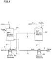
- Figure 1 shows a schematic overview of an original toluene nitration to dinitrotoluene process.
- the nitration is carried out in two steps.
- the first step is a mononitrotoluene nitration and the second step is a dinitrotoluene nitration.
- the first process step is feeding a toluene comprising first stream 1 and a nitric acid comprising second stream 2 into a first reactor R1.
- the first stream 1 and the second stream 2 are reacting to a first reaction mixture 3.
- the first reaction mixture 3 comprises a first liquid/liquid mixed phase of an organic phase comprising of mononitrotoluene and dinitrotoluene and an acid phase. Both phases are mutual dissolved.
- the liquid/liquid mixed acid phase of the first reaction mixture 3 comprises sulfuric acid in the range from about 70wt% to about 71wt%, nitric acid in the range from about 0.1wt% to about 1wt%, nitrous acid in the range from about 0.4wt% to about 1.5wt% and a certain amount of Nitrogene oxides gas resulting from the decomposition of nitrous acid.
- the first reaction mixture 3 is fed into a first separation device S1, which is a dynamic separator.
- the first separation device S1 is separating the reaction mixture 3 into a first forward stream 4 having a flow direction to the second process step and a first backward stream 5 having a flow direction back to the first reactor R1.
- the first forward stream 4 should comprise of as much organic phase like mononitrotoluene as possible and the first backward stream 5 should cycle the acid phase back to the first reactor R1.
- the second process step is feeding the first forward stream 4, a nitric acid comprising third stream 6 and a sulfuric acid comprising fourth stream 7 into a second reactor R2.
- the first forward stream 4 the nitric acid comprising third stream 6 and the sulfuric acid comprising fourth stream 7 are reacting to a second reaction mixture 8.
- the second reaction mixture 8 comprises a first liquid/liquid mixed phase of an organic phase comprising of mononitrotoluene and dinitrotoluene and an acid phase. Both phases are mutual dissolved.
- the liquid/liquid mixed acid phase of the second reaction mixture 8 comprises sulfuric acid in the range from about 78wt% to about 79wt%, nitric acid in the range from about 0.5wt% to about 1.5wt%, nitrous acid in the range from about 0.8wt% to about 1.5wt% and a certain amount of Nitrogene oxides gas resulting from the decomposition of nitrous acid.
- the second reaction mixture 8 is fed into a second separation device S2, which is a dynamic separator.
- the second separation device S2 is separating the second reaction mixture 8 into a second forward stream 9 having a flow direction to process output and a second backward stream 10 having a flow direction back to the first reactor R1.
- the second forward stream 9 should comprise of as much organic phase like crude dinitrotoluene as possible and the second backward stream 10 should cycle the acid phase back to the first reactor R1.
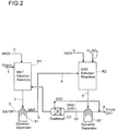
- FIG 2 shows a schematic overview of the original toluene nitration to dinitrotoluene process of figure 1 with the difference that in the second process step a coalsecer C2 is installed.
- the coalescer C2 is fine separating the second backward stream 10. By the fine separation as much organic phase like crude dinitrotoluene as possible should access the second forward stream 9 having a flow direction to process output and as much acid phase as possible should be cycled back to the first reactor R1.
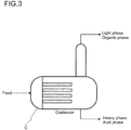
- FIG 3 shows a schematic overview of a coalescer C.
- the coalescer C is fed by a stream which is fine separated into an organic phase and an acid phase.
- the organic phase is a light phase compared to the acid phase as a heavy phase.
- the coalescer C is a predominantly cylindrical device having a horizontal axis, this horizontal axis differing from a horizontal line with a gradient. This gradient improves the removal of gas along the gradient and out of the coalsecer C.
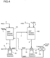
- FIG 4 shows a schematic overview of the original toluene nitration to dinitrotoluene process of figure 1 with the difference that in the second process step a coalsecer C2 is installed.
- the coalescer C2 is fine separating the second forward stream 9. By the fine separation as much organic phase like crude dinitrotoluene as possible should access process output and as much acid phase as possible should be cycled back to the first reactor R1 in the second backward stream 10.
- FIG 5 shows a schematic overview of the original toluene nitration to dinitrotoluene process of figure 1 with the difference that in the first process step a coalsecer C1 is installed.
- the coalescer C1 is fine separating the first forward stream 4. By the fine separation as much organic phase comprising mononitrotoluene as possible should access the second reactor R2 and as much acid phase as possible should be cycled back to the first reactor R1 in the first backward stream 5.
- FIG 6 shows a schematic overview of the original toluene nitration to dinitrotoluene process of figure 1 with the difference that in the first process step a coalsecer C1 is installed.
- the coalescer C1 is fine separating the first backward stream 5. By the fine separation as much organic phase comprising mononitrotoluene as possible should access the second reactor R2 and as much acid phase as possible should be cycled back to the first reactor R1 in the first backward stream 5.
- the following tables 1 and 2 show production data as examples according to the coalescer C as described in figure 3 .
- the tables differ regarding to the residence times of 1 and 3 minutes in the coalscer, which results in different feed rates and/or loads for coalesce during plant trials.
- the residence times can also be defined as a percentage of coalesced rates/or loads.
- Tab. 1 Experimental data of plant trials with the resident time of 1 minute in the coalscer.
Landscapes
- Chemical & Material Sciences (AREA)
- Organic Chemistry (AREA)
- Physics & Mathematics (AREA)
- Thermal Sciences (AREA)
- Chemical Kinetics & Catalysis (AREA)
- Organic Low-Molecular-Weight Compounds And Preparation Thereof (AREA)
Description
- The invention relates to a separation method in a toluene to dinitrotoluene process by separating an organic phase from a mixed acid phase by the use of a coalescer.
- The organic phase comprises mono- and/or dinitrotoluene. The mixed acid phase comprises sulfuric acid, nitric acid, nitrous acid and nitrogene oxides gas e.g. resulting from the decomposition of nitrous acid.
- The nitration of toluene to dinitrotoluene is well known. In general a toluene to dinitrotoluene process consists of two steps. In a first step toluene reacts with nitric acid in a nitration reactor to mononitrotoluene as an organic phase and in a second step the mononitrotoluene reacts with nitric acid and sulfuric acid in a nitration reactor to dinitrotoluene as an organic phase.
- The effluent of each of the reactors is a mixture of an organic phase and a mixed acid phase. In order to obtain a high concentration of an organic phase the organic phase can be separated from the acid phase. Several methods to separate the organic phase from the acid phase of the effluent of reactors exist.
- A dynamic separator is used in
US7851661 B2 for the separation of a reaction product into an organic phase comprising mononitrotoluene and an aqueous phase comprising sulfuric acid. The dynamic separation occurs by centrifugal force or static settlement separation by gravity. - A problem of dynamic separation is that dynamic separators cannot completely separate organics phase from mixed acid phase due to limitation in the technical structure by which a separator is equipped. The limitation of dynamic separator technical structure is that two phases interphase is controlled in the equipment by so-called regular rings which function similar to a wear in a static settler at heavy and light phases discharger sides, and the regular ring is a kind of fixed device in the equipment which can not be controlled during normal operation. The only way of adjustment of the equipment is to shut down and disassemble the dynamic separator and change the regular rings into a rings of different dimensions. A shut down of the dynamic separator decreases the efficiency of the separation process.
- Also during operation, as concentration, the density of both phases in reactor products is always changing from time to time and having a fixed separator e.g. with a wear provided, the entrainments is always possible to happen in both phases.
- The disadvantages of such entrainments are an increase of internal circulation in a nitration system thereby also reducing the reaction residence time in a reactor and a possible change of the two phases ratio in reactors. Also, potential safety risks exist in case the concentration of certain reactor products increases above a critical level. One example for a potential risk of explosion is if the toluene concentration within a mononitrotoluene reactor is increasing above a certain level resulting in by-products such as black acid. A reaction possibility for the by-product of black acid components can be shown as follows:
NO + NO2 + 2H2SO4 → 2NOHSO4 + H2O
C7H8 + 2NOHSO4 + 3H2SO4 → (C7H8) * (NOHSO4)2 * (H2SO4)3
- Having black complex component provided a potential decomposition risk exists.
- The black acid component can occur when residence times in a mononitrotoluene reactor is too short or in case there is a lack of nitric acid. An advantage of the present invention is a reduction of the internal circulation of about 10% which results in a reduction of residence time in the mononitrotoluene reactor of about 10%. The benefits are less safety risks and an improved and efficient control of the toluene concentration. By this the bottleneck of the production plant operation is removed.
- In
US5902910A a reaction product is separated into an organic phase containing mononitrotoluene and a first spent acid phase by a phase separator. Also inUS5902910A an organic phase containing dinitrotoluene is separated from a second spent acid phase by a phase separator. - In the
US6506948B1 a phase separator is mentioned after certain stages of production but no more details regarding the kind of separator and/or the basic principle of the separation method and/or the separation process are given. - A general disadvantage of phase separators is plugging which often occurs after a certain operation time. Reasons for plugging can be that corroded particles get stuck in devices and/or fouling products block the devices. As a result of plugging the production process has to be shutdown and phase separators to be disassembled and cleaned. A shut down of a separator decreases the efficiency of the separation process.
- Therefore it is the objective problem of the invention to provide an improved separation method with an increased separation efficiency and which needs less residence time for separation and overcomes the afore mentioned disadvantages.
- The objective problem is solved by a separation method in a toluene to dinitrotoluene process, said method with a first process step comprising feeding a toluene comprising first stream and a nitric acid comprising second stream into a first reactor, reacting of the toluene comprising first stream and the nitric acid comprising second stream within the first reactor to a first reaction mixture, said first reaction mixture comprising a first liquid/liquid mixed phase of an acid phase and an organic phase comprising mononitrotoluene, feeding the first reaction mixture into a first separation device, separating the first reaction mixture within the first separation device into a first forward stream having a flow direction to a second process step and a first backward stream having a flow direction back to the first reactor, said method having a second process step comprising feeding the first forward stream into a second reactor, feeding a nitric acid comprising third stream and a sulfuric acid comprising fourth stream into the second reactor, reacting of the first forward stream, the nitric acid comprising third stream and the sulfuric acid comprising fourth stream within the second reactor to a second reaction mixture, said second reaction mixture comprising a second liquid/liquid mixed acid phase and an organic phase comprising mononitrotoluene and dinitrotoluene, feeding the second reaction mixture into a second separation device, separating the second reaction mixture within the second separation device into a second forward stream having a flow direction to a process output and a second backward stream having a flow direction back to the first reactor, wherein fine separating of at least one of the streams after the first separation step and/or the second separation step in a coalescer is carried out.
- Under a reactor according to the present invention a device for containing and controlling a chemical reaction is understood.
- Under a separation device according to the present invention a device for the separation of different substances is understood. A separation device according to the present invention preferably is a centrifugal separator.
- Under a forward stream according to the present invention a stream with a downstream direction in a process, preferably a stream to a further process step, a stream to a process output is understood.
- Under a backward stream according to the present invention a stream with an upstream direction in a process, preferably a stream to a previous process step, a stream to a process input is understood.
- Under a process output according to the present invention an output of a product of a final process step, preferably the output of the product dinitrotoluene is understood.
- Under fine separating according to the present invention a separation of a liquid/liquid mixed acid phase from an organic phase and a separation of a gas phase is understood. The mixed acid phase preferably comprises sulfuric acid, nitric acid and nitrous acid. The organic phase preferably comprises dinitrotoluene and/or mononitrotoluene. The gas phase preferably comprises nitrogene oxides.
- Under a first separation step according to the present invention a separation step which is upstream of a second separation step is understood. Prefarably in the first separation step a process stream is separated by a dynamic separator.
- Under a second separation step according to the present invention a separation step which is downstream of a first separation step is understood. Prefarably in the second separation step a process stream is separated by a static separator. An advantage of a static separator in the second separation step is that the residence time can be reduced which increases the throughput in a process.
- Under a coalescer according to the present invention a static separator is understood. The static separation is based on a static settelment and/or on internals of the separator for separation of phases. Preferably internals are mesh types, wire types, fiber candles, vane packs and/or other structures inside the separator separating the phases. In case of only static settlement also devices without internals can be used.
- Preferably the coalescer is a mechanical and/or an electrostatic coalescer. Mechanical coalescers use filters and/or internals like baffles while electrostatic coalescers use direct current (DC) or alternating current (AC) electric fields or combinations thereof.
- Preferably the coalescer separates a mixed acid phase from an organic phase of a liquid/liquid phase and also separates a gas phase.
- In case a phase is corrosive a preferred material for of least the elements of a separator which are in contact with the corrosive phase is polytetrafluorethylene (PTFE).
- Examples of preferred coalescers and/or internals are of the vendors Franken and/or Pall, more preferred is the internal Pall type LCS4H2HH. The preferred pore sizes of internal fiber webs can be in the range of about 10 to 20 micron. For the separation of a gas phase the installation of a gas bag is preferred.
- A separation method wherein fine separating the second backward stream having a flow direction back to the first reactor in a coalescer is carried out.
- A separation method wherein fine separating the second forward stream having a flow direction to the process output in a coalescer is carried out.
- A separation method wherein fine separating the first forward stream having a flow direction to the second process step in a coalescer is carried out.
- A separation method wherein fine separating the first backward stream having a flow direction back to the first reactor in a coalescer is carried out.
- A separation method wherein the second backward stream having a flow direction back to the first reactor comprises a liquid/liquid mixed acid phase comprising sulfuric acid concentration in the range from about 70 wt% to about 95 wt%, preferably from about 75 wt% to about 85 wt%, more preferably from about 78 wt% to about 79 wt% and nitric acid in the range from about 0.1 wt% to about 5 wt%, preferably from about 0.2 wt% to about 3 wt%, more preferably from about 0.5 wt% to about 1.5 wt%, and mononitrotoluene and dinitrotoluene as an organic phase and combinations thereof.
- A separation method wherein fine separating the second forward stream having a flow direction to the process output comprises a liquid/liquid mixed acid phase comprising sulfuric acid in the range from about 0.1 wt% to about 20 wt%, preferably from about 0.2 wt% to about 15 wt%, more preferably from about 0.3 wt% to about 10 wt% and nitric acid in the range from about 0.1 wt% to about 10 wt%, preferably from about 0.2 wt% to about 5 wt%, more preferably from about 0.3 wt% to about 3 wt%, and mononitrotoluene and dinitrotoluene as an organic phase and combinations thereof.
- A separation method wherein fine separating the first forward stream having a flow direction to a second process step comprises a liquid/liquid mixed acid phase comprising sulfuric acid in the range from about 0.1 wt% to about 20 wt%, preferably from about 0.2 wt% to about 15 wt%, more preferably from about 0.3 wt% to about 10 wt% and nitric acid in the range from about 0.1 wt% to about 15 wt%, preferably from about 0.2 wt% to about 5 wt%, more preferably from about 0.3 wt% to about 1.5 wt%, and mononitrotoluene and dinitrotoluene as an organic phase and combinations thereof.
- A separation method wherein fine separating the first backward stream having a flow direction back to the first reactor comprises a liquid/liquid mixed acid phase comprising sulfuric acid in the range from about 60 wt% to about 80 wt%, preferably from about 65 wt% to about 75 wt%, more preferably from about 69 to about 72 wt% and nitric acid in the range from about 0.1 wt% to about 5 wt%, preferably from about 0.2 wt% to about 3 wt%, more preferably from about 0.3 wt% to about 1.5 wt%, and mononitrotoluene and dinitrotoluene as an organic phase and combinations thereof.
- A separation method wherein the toluene concentration in the first reactor is in the range from about 0 wt% to about 10 wt%, preferably from about 0.1 wt% to about 7 wt%, more preferably from about 0.2 wt% to about 5 wt%.
- A separation method wherein the coalescer is a predominantly cylindrical device having a longitudinal axis, this longitudinal axis differing from a horizontal line with a gradient in the range from 0.2° to about 5°, more preferably from about 0.5° to about 2°.
- A separation method wherein at least one of the streams feeding the coalescer has a dynamic viscosity in the range from about 0.1 mPas to about 20 mPas, preferably from about 0.2 mPas to about 15 mPas, more preferably from about 1 mPas to about 7 mPas.
- A separation method wherein at least one of the streams feeding the coalescer has a interfacial tension in the range from about 0.5 mN/m to about 95 mN/m, preferably from about 10 mN/m to about 90 mN/m, more preferably from about 40 mN/m to about 80 mN/m.
- For determination of the interfacial tension according to the present invention the standard Du Noüy ring method is used.
- A separation method wherein at least one of the streams feeding the coalescer has a flow rate per surface area through the coalsecer in the range from about 2 m3/h/m2 to about 10 m3/h/m2, preferably from about 3 m3/h/m2 to about 8 m3/h/m2, more preferably from about 4 m3/h/m2 to about 6 m3/h/m2.
- A separation method wherein at least one of the streams feeding the coalescer has a residence time in the coalsecer in the range from about 1 min to about 30 min, preferably from about 2 min to about 10 min, more preferably from about 3 min to about 6 min.
- Under residence time according to the present invention is understood the time starting when a feed enters the coalescer to the time this feed exits the coalescer.
- The invention is explained below with reference to figures and tables.
- The figures show in detail:
-
Fig. 1 : a schematic overview of an original toluene nitration to dinitrotoluene process, -
Fig. 2 : a schematic overview of the toluene nitration to dinitrotoluene process with a coalescer installed after the dynamic separator of the DNT nitration reactor in the backward stream to the MNT nitration reactor, -
Fig. 3 : a schematic overview of a coalescer, -
Fig. 4 : a schematic overview of the toluene nitration to dinitrotoluene process with a coalescer installed after the dynamic separator of the DNT nitration reactor in direction of the flow output stream, -
Fig. 5 : a schematic overview of the toluene nitration to dinitrotoluene process with a coalescer installed after the dynamic separator of the MNT nitration reactor in the flow output stream to the DNT nitration reactor, -
Fig. 6 : a schematic overview of the toluene nitration to dinitrotoluene process with a coalescer installed after the dynamic separator of the MNT nitration reactor in the backward stream. - The identical reference characters in the figures stand for the same or corresponding features.
-
Figure 1 shows a schematic overview of an original toluene nitration to dinitrotoluene process. In the toluene nitration to dinitrotoluene process, normally the nitration is carried out in two steps. The first step is a mononitrotoluene nitration and the second step is a dinitrotoluene nitration. The first process step is feeding a toluene comprisingfirst stream 1 and a nitric acid comprisingsecond stream 2 into a first reactor R1. In the first reactor R1 thefirst stream 1 and thesecond stream 2 are reacting to afirst reaction mixture 3. Thefirst reaction mixture 3 comprises a first liquid/liquid mixed phase of an organic phase comprising of mononitrotoluene and dinitrotoluene and an acid phase. Both phases are mutual dissolved. As an example the liquid/liquid mixed acid phase of thefirst reaction mixture 3 comprises sulfuric acid in the range from about 70wt% to about 71wt%, nitric acid in the range from about 0.1wt% to about 1wt%, nitrous acid in the range from about 0.4wt% to about 1.5wt% and a certain amount of Nitrogene oxides gas resulting from the decomposition of nitrous acid. Thefirst reaction mixture 3 is fed into a first separation device S1, which is a dynamic separator. The first separation device S1 is separating thereaction mixture 3 into a firstforward stream 4 having a flow direction to the second process step and a firstbackward stream 5 having a flow direction back to the first reactor R1. The firstforward stream 4 should comprise of as much organic phase like mononitrotoluene as possible and the firstbackward stream 5 should cycle the acid phase back to the first reactor R1. The second process step is feeding the firstforward stream 4, a nitric acid comprisingthird stream 6 and a sulfuric acid comprisingfourth stream 7 into a second reactor R2. In the second reactor R2 the firstforward stream 4, the nitric acid comprisingthird stream 6 and the sulfuric acid comprisingfourth stream 7 are reacting to asecond reaction mixture 8. Thesecond reaction mixture 8 comprises a first liquid/liquid mixed phase of an organic phase comprising of mononitrotoluene and dinitrotoluene and an acid phase. Both phases are mutual dissolved. As an example the liquid/liquid mixed acid phase of thesecond reaction mixture 8 comprises sulfuric acid in the range from about 78wt% to about 79wt%, nitric acid in the range from about 0.5wt% to about 1.5wt%, nitrous acid in the range from about 0.8wt% to about 1.5wt% and a certain amount of Nitrogene oxides gas resulting from the decomposition of nitrous acid. Thesecond reaction mixture 8 is fed into a second separation device S2, which is a dynamic separator. The second separation device S2 is separating thesecond reaction mixture 8 into a secondforward stream 9 having a flow direction to process output and a secondbackward stream 10 having a flow direction back to the first reactor R1. The secondforward stream 9 should comprise of as much organic phase like crude dinitrotoluene as possible and the secondbackward stream 10 should cycle the acid phase back to the first reactor R1. -
Figure 2 shows a schematic overview of the original toluene nitration to dinitrotoluene process offigure 1 with the difference that in the second process step a coalsecer C2 is installed. The coalescer C2 is fine separating the secondbackward stream 10. By the fine separation as much organic phase like crude dinitrotoluene as possible should access the secondforward stream 9 having a flow direction to process output and as much acid phase as possible should be cycled back to the first reactor R1. -
Figure 3 shows a schematic overview of a coalescer C. The coalescer C is fed by a stream which is fine separated into an organic phase and an acid phase. In common the organic phase is a light phase compared to the acid phase as a heavy phase. The coalescer C is a predominantly cylindrical device having a horizontal axis, this horizontal axis differing from a horizontal line with a gradient. This gradient improves the removal of gas along the gradient and out of the coalsecer C. -
Figure 4 shows a schematic overview of the original toluene nitration to dinitrotoluene process offigure 1 with the difference that in the second process step a coalsecer C2 is installed. The coalescer C2 is fine separating the secondforward stream 9. By the fine separation as much organic phase like crude dinitrotoluene as possible should access process output and as much acid phase as possible should be cycled back to the first reactor R1 in the secondbackward stream 10. -
Figure 5 shows a schematic overview of the original toluene nitration to dinitrotoluene process offigure 1 with the difference that in the first process step a coalsecer C1 is installed. The coalescer C1 is fine separating the firstforward stream 4. By the fine separation as much organic phase comprising mononitrotoluene as possible should access the second reactor R2 and as much acid phase as possible should be cycled back to the first reactor R1 in the firstbackward stream 5. -
Figure 6 shows a schematic overview of the original toluene nitration to dinitrotoluene process offigure 1 with the difference that in the first process step a coalsecer C1 is installed. The coalescer C1 is fine separating the firstbackward stream 5. By the fine separation as much organic phase comprising mononitrotoluene as possible should access the second reactor R2 and as much acid phase as possible should be cycled back to the first reactor R1 in the firstbackward stream 5. - The following tables 1 and 2 show production data as examples according to the coalescer C as described in
figure 3 . The tables differ regarding to the residence times of 1 and 3 minutes in the coalscer, which results in different feed rates and/or loads for coalesce during plant trials. The residence times can also be defined as a percentage of coalesced rates/or loads.Tab. 1: Experimental data of plant trials with the resident time of 1 minute in the coalscer. Coalescer residence time 1mins 1 FEED inlet 2 light phase outlet 3 heavy phase outlet Mass Frac DNT (a) (MNT, toluene) 14,6 wt% 91,2 wt% 7,9 wt% HNO3 0,8 wt% 3,1 wt% 0,6 wt% H2SO4 71,7 wt% 0,8 wt% 77,6 wt% HNO2 (NOx) 1-1.5 wt% 1,5-2 wt% 1,0-1.5 wt% H2O 11,5 wt% 0,6 wt% 12,9 wt% CRESOL (b) 50-200ppm 50-200ppm 50-200ppm other organics /acids/inerts(c) 0,1-0.2 wt% 0.1-2 wt% 0,01-0.2 wt% Temperature C 65 65 65 Density kg/cum 1551 1337 1556 (a) DNT containing tracing MNT and toluene
(b) Cresol including isomers of nitrocresol, dinitrocresol, trinitrocresol,
(c) other organics/acids/inerts including acetic acid, formic acid, oxalic acid, HCN, CO, CO2 etc.Tab. 2: Experimental data of plant trials with the resident time of 3minutes in the coalscer. Coalescer residence time 3mins 1 FEED inlet 2 light phase outlet 3 heavy phase outlet Mass Frac DNT (a) (MNT, toluene) 14.6 wt% 93.0 wt% 4.9 wt% HNO3 0.8 wt% 2.1 wt% 0.6 wt% H2SO4 71.7 wt% 0.6 wt% 80.1 wt% HNO2 (NOx) 1-1.5wt% 1.5-2wt% 1-1.5wt% H2O 11.5 wt% 0.6 wt% 13.3 wt% CRESOL (b) 50-200ppm 50-200ppm 50-200ppm other organics /acids/inerts (c) 0.1-0.2wt% 0.1-2wt% 0.01-0.2wt% Temperature C 65 65 65 Density kg/cum 1550 1334 1558 (a) DNT containing tracing MNT and toluene
(b) Cresol including isomers of nitrocresol, dinitrocresol, trinitrocresol,
(c) other organics/acids/inerts including acetic acid, formic acid, oxalic acid, HCN, CO, CO2 etc
Claims (15)
- A separation method in a toluene to dinitrotoluene process, said method with a first process step comprising:- feeding a toluene comprising first stream (1) and a nitric acid comprising second stream (2) into a first reactor (R1),- reacting of the toluene comprising first stream (1) and the nitric acid comprising second stream (2) within the first reactor (R1) to a first reaction mixture (3), said first reaction mixture (3) comprising a first liquid/liquid mixed phase of an acid phase and an organic phase comprising mononitrotoluene,- feeding the first reaction mixture (3) into a first separation device (S1),- separating the first reaction mixture (3) within the first separation device (S1) into a first forward stream (4) having a flow direction to a second process step and a first backward stream (5) having a flow direction back to the first reactor (R1),said method having a second process step comprising:- feeding the first forward stream (4) into a second reactor (R2),- feeding a nitric acid comprising third stream (6) and a sulfuric acid comprising fourth stream (7) into the second reactor (R2),- reacting of the first forward stream (4), the nitric acid comprising third stream (6) and the sulfuric acid comprising fourth stream (7) within the second reactor (R2) to a second reaction mixture (8), said second reaction mixture (8) comprising a second liquid/liquid mixed acid phase and an organic phase comprising mononitrotoluene and dinitrotoluene,- feeding the second reaction mixture (8) into a second separation device (S2),- separating the second reaction mixture (8) within the second separation device (S2) into a second forward stream (9) having a flow direction to a process output and a second backward stream (10) having a flow direction back to the first reactor (R1),wherein
fine separating of at least one of the streams (4, 5, 9,10) after the first separation step (S1) and/or the second separation step (S2) is carried out in a coalescer. - The separation method as claimed in claim 1, wherein fine separating the second backward stream (10) having a flow direction back to the first reactor (R1) is carried out in a coalescer.
- The separation method as claimed in claims 1 and 2, wherein fine separating the second forward stream (9) having a flow direction to the process output is carried out in a coalescer.
- The separation method as claimed in claims 1 to 3, wherein fine separating the first forward stream (4) having a flow direction to the second process step is carried out in a coalescer.
- The separation method as claimed in claims 1 to 4, wherein fine separating the first backward stream (5) having a flow direction back to the first reactor (R1) is carried out in a coalescer.
- The separation method as claimed in claims 1 to 5, wherein the second backward stream (10) having a flow direction back to the first reactor (R1) comprises a liquid/liquid mixed acid phase comprising sulfuric acid concentration in the range from 70 wt% to 95 wt% and nitric acid in the range from 0.1 wt% to 5 wt%, and mononitrotoluene and dinitrotoluene as an organic phase.
- The separation method as claimed in claims 1 to 6, wherein fine separating the second forward stream (9) having a flow direction to the process output comprises a liquid/liquid mixed acid phase comprising sulfuric acid in the range from 0.1 wt% to 20 wt% and nitric acid in the range from 0.1 wt% to 10 wt%, and mononitrotoluene and dinitrotoluene as an organic phase.
- The separation method as claimed in claims 1 to 7, wherein fine separating the first forward stream (4) having a flow direction to a second process step comprises a liquid/liquid mixed acid phase comprising sulfuric acid in the range from 0.1 wt% to 20 wt% and nitric acid in the range from 0.1 wt% to 15 wt%, and mononitrotoluene and dinitrotoluene as an organic phase.
- The separation method as claimed in claims 1 to 8, wherein fine separating the first backward stream (5) having a flow direction back to the first reactor (R1) comprises a liquid/liquid mixed acid phase comprising sulfuric acid in the range from 60 wt% to 80 wt% and nitric acid in the range from 0.1 wt% to 5 wt%, and mononitrotoluene and dinitrotoluene as an organic phase.
- The separation method as claimed in claims 1 to 9, wherein the toluene concentration in the first reactor (R1) is in the range from 0 wt% to 10 wt%.
- The separation method as claimed in claims 1 to 10, wherein the coalescer is a predominantly cylindrical device having a longitudinal axis, this longitudinal axis differing from a horizontal line with a gradient in the range from 0.2° to 5°.
- The separation method as claimed in claims 1 to 11, wherein at least one of the streams (4, 5, 9,10) feeding the coalescer has a dynamic viscosity in the range from 0.1 mPas to 20 mPas.
- The separation method as claimed in claims 1 to 12, wherein at least one of the streams (4, 5, 9,10) feeding the coalescer has a interfacial tension in the range from 40 mN/m to 80 mN/m.
- The separation method as claimed in claims 1 to 13, wherein at least one of the streams (4, 5, 9,10) feeding the coalescer has a flow rate per surface area through the coalsecer in the range from 2 m3/h/m2 to 10 m3/h/m2, preferably from 3 m3/h/m2 to 8 m3/h/m2, more preferably from 4 m3/h/m2 to 6 m3/h/m2.
- The separation method as claimed in claims 1 to 14, wherein at least one of the streams (4, 5, 9,10) feeding the coalescer has a residence time in the coalsecer in the range from 1 min to 30 min, preferably from 2 min to 10 min, more preferably from 3 min to 6 min.
Applications Claiming Priority (2)
| Application Number | Priority Date | Filing Date | Title |
|---|---|---|---|
| PCT/CN2012/086999 WO2014094270A1 (en) | 2012-12-20 | 2012-12-20 | Separation method for dinitrotoluene and mixed acid in toluene to dinitrotoluene process |
| PCT/EP2013/076002 WO2014095469A1 (en) | 2012-12-20 | 2013-12-10 | Separation method for dinitrotoluene and mixed acid in a toluene to dinitrotoluene process |
Publications (2)
| Publication Number | Publication Date |
|---|---|
| EP2935200A1 EP2935200A1 (en) | 2015-10-28 |
| EP2935200B1 true EP2935200B1 (en) | 2016-08-24 |
Family
ID=49759292
Family Applications (1)
| Application Number | Title | Priority Date | Filing Date |
|---|---|---|---|
| EP13802958.2A Active EP2935200B1 (en) | 2012-12-20 | 2013-12-10 | Separation method for dinitrotoluene and mixed acid in a toluene to dinitrotoluene process |
Country Status (5)
| Country | Link |
|---|---|
| US (1) | US9284257B2 (en) |
| EP (1) | EP2935200B1 (en) |
| KR (1) | KR102205360B1 (en) |
| SA (1) | SA515360559B1 (en) |
| WO (2) | WO2014094270A1 (en) |
Families Citing this family (5)
| Publication number | Priority date | Publication date | Assignee | Title |
|---|---|---|---|---|
| US10698424B2 (en) * | 2014-11-20 | 2020-06-30 | Covestro Deutschland Ag | Method for continuously producing a product by way of at least two coupled-together chemical reactions |
| CN107986249B (en) * | 2017-10-31 | 2020-08-04 | 湖北东方化工有限公司 | Method for removing nitrotoluene from dilute nitric acid after nitrotoluene waste acid denitration |
| CN110170185B (en) * | 2019-05-30 | 2023-07-25 | 湖北东方化工有限公司 | Device and method for separating waste sulfuric acid nitro compounds |
| CN117229148A (en) * | 2023-09-28 | 2023-12-15 | 老河口华辰化学有限公司 | Method for preparing o-chloronitrotoluene mixture |
| WO2026077860A1 (en) * | 2024-10-09 | 2026-04-16 | Covestro Deutschland Ag | Method for separating w/o emulsions |
Family Cites Families (9)
| Publication number | Priority date | Publication date | Assignee | Title |
|---|---|---|---|---|
| US5902910A (en) | 1997-09-19 | 1999-05-11 | Air Products And Chemicals, Inc. | Weak acid process for producing dinitrotoluene |
| US6506948B1 (en) | 2002-02-07 | 2003-01-14 | Air Products And Chemicals, Inc. | Toluene extraction of dinitrotoluene wash water |
| DE102004005913A1 (en) * | 2004-02-05 | 2005-08-25 | Basf Ag | Process for the preparation of dinitrotoluene |
| DE102006033722A1 (en) * | 2006-07-21 | 2008-01-24 | Bayer Materialscience Ag | Process for the preparation of dinitrotoluene |
| US20130041188A1 (en) | 2011-08-09 | 2013-02-14 | Basf Se | Process for purifying wastewaters from the workup of crude aromatic nitro compounds |
| US8697921B2 (en) | 2011-08-09 | 2014-04-15 | Basf Se | Process for purifying wastewaters from the workup of crude aromatic nitro compounds |
| US8895783B2 (en) | 2012-02-07 | 2014-11-25 | Basf Se | Monitoring of the stoichiometric ratio in the reaction of nitroaromatics with hydrogen |
| US9249083B2 (en) | 2012-04-25 | 2016-02-02 | Basf Se | Process for scrubbing dinitrotoluene |
| US9115049B2 (en) | 2012-10-11 | 2015-08-25 | Basf Se | Process for obtaining pure aniline |
-
2012
- 2012-12-20 WO PCT/CN2012/086999 patent/WO2014094270A1/en not_active Ceased
-
2013
- 2013-12-10 EP EP13802958.2A patent/EP2935200B1/en active Active
- 2013-12-10 KR KR1020157019134A patent/KR102205360B1/en active Active
- 2013-12-10 WO PCT/EP2013/076002 patent/WO2014095469A1/en not_active Ceased
- 2013-12-10 US US14/653,687 patent/US9284257B2/en active Active
-
2015
- 2015-06-10 SA SA515360559A patent/SA515360559B1/en unknown
Also Published As
| Publication number | Publication date |
|---|---|
| KR20150120948A (en) | 2015-10-28 |
| WO2014095469A1 (en) | 2014-06-26 |
| WO2014094270A1 (en) | 2014-06-26 |
| US20150329469A1 (en) | 2015-11-19 |
| SA515360559B1 (en) | 2016-09-05 |
| US9284257B2 (en) | 2016-03-15 |
| KR102205360B1 (en) | 2021-01-21 |
| EP2935200A1 (en) | 2015-10-28 |
Similar Documents
| Publication | Publication Date | Title |
|---|---|---|
| US9284257B2 (en) | Separation method for dinitrotoluene and mixed acid in a toluene to dinitrotoluene process | |
| CN102471092B (en) | Washing system for nitroaromatic compounds | |
| US8410323B2 (en) | Process for downstream recovery of nitroalkane using dividing wall column | |
| JP2008024706A (en) | Method for producing dinitrotoluene | |
| EP2906315B1 (en) | A liquid-liquid extraction system and process for use thereof | |
| CN104927907B (en) | Alkylation product desulphurization and deacidifying method and device | |
| CA2984027A1 (en) | Apparatus and process for separating asphaltenes from an oil-containing fuel | |
| CN102503010A (en) | Method for treating polycarbonate waste water and recycling resin glue solution and solvent | |
| US11897794B2 (en) | Processes and systems for treating sour water | |
| EP2853515A1 (en) | A system and process for water treatment | |
| CN105102419B (en) | The separation method of dinitrotoluene (DNT) and mixed acid in the method for toluene to dinitrotoluene (DNT) | |
| CN106883128B (en) | Method for removing heterogeneous catalyst from reaction product and method for preparing aromatic amine | |
| US5132016A (en) | Solvent prestripping in a zr/hf separation liquid-liquid extraction (llx) circuit | |
| EP2534126A1 (en) | Removal of non-aromatic impurities from a nitration process | |
| EP1690850B1 (en) | Process for the production of dinitrotoluene | |
| CN113924284A (en) | Method and device for preparing nitrobenzene | |
| JP5781166B2 (en) | Apparatus and method using nitroalkane as an azeotropic agent for azeotropic removal of water from hydrous acid solutions | |
| CN104284882B (en) | A kind of method for purifying the organic solution obtained from oxime synthesis zone | |
| KR100721050B1 (en) | Liquid-liquid extracting method | |
| CN103502200A (en) | An improved process for the production of hexamethylenediamine | |
| WO2001074468A2 (en) | Processes for separation of oil/water emulsions | |
| CN114436359B (en) | Method for extracting and recovering N, N-dimethylacetamide in wastewater | |
| CN116836393B (en) | Process for preparing methyl hydrogen silicone oil | |
| CN118663182A (en) | Device system and process for preparing polysiloxane by hydrolyzing organic silicon monomer with concentrated acid | |
| CN118255650A (en) | A method for recovering low-purity bisphenol A and its system and application |
Legal Events
| Date | Code | Title | Description |
|---|---|---|---|
| PUAI | Public reference made under article 153(3) epc to a published international application that has entered the european phase |
Free format text: ORIGINAL CODE: 0009012 |
|
| 17P | Request for examination filed |
Effective date: 20150720 |
|
| AK | Designated contracting states |
Kind code of ref document: A1 Designated state(s): AL AT BE BG CH CY CZ DE DK EE ES FI FR GB GR HR HU IE IS IT LI LT LU LV MC MK MT NL NO PL PT RO RS SE SI SK SM TR |
|
| AX | Request for extension of the european patent |
Extension state: BA ME |
|
| REG | Reference to a national code |
Ref country code: DE Ref legal event code: R079 Ref document number: 602013010775 Country of ref document: DE Free format text: PREVIOUS MAIN CLASS: C07C0201080000 Ipc: C07C0201160000 |
|
| GRAP | Despatch of communication of intention to grant a patent |
Free format text: ORIGINAL CODE: EPIDOSNIGR1 |
|
| DAX | Request for extension of the european patent (deleted) | ||
| RIC1 | Information provided on ipc code assigned before grant |
Ipc: C07C 201/08 20060101ALI20160225BHEP Ipc: C07C 201/16 20060101AFI20160225BHEP |
|
| INTG | Intention to grant announced |
Effective date: 20160323 |
|
| GRAS | Grant fee paid |
Free format text: ORIGINAL CODE: EPIDOSNIGR3 |
|
| GRAA | (expected) grant |
Free format text: ORIGINAL CODE: 0009210 |
|
| AK | Designated contracting states |
Kind code of ref document: B1 Designated state(s): AL AT BE BG CH CY CZ DE DK EE ES FI FR GB GR HR HU IE IS IT LI LT LU LV MC MK MT NL NO PL PT RO RS SE SI SK SM TR |
|
| REG | Reference to a national code |
Ref country code: GB Ref legal event code: FG4D |
|
| REG | Reference to a national code |
Ref country code: CH Ref legal event code: EP |
|
| REG | Reference to a national code |
Ref country code: AT Ref legal event code: REF Ref document number: 822936 Country of ref document: AT Kind code of ref document: T Effective date: 20160915 |
|
| REG | Reference to a national code |
Ref country code: IE Ref legal event code: FG4D |
|
| REG | Reference to a national code |
Ref country code: DE Ref legal event code: R096 Ref document number: 602013010775 Country of ref document: DE |
|
| REG | Reference to a national code |
Ref country code: LT Ref legal event code: MG4D |
|
| REG | Reference to a national code |
Ref country code: NL Ref legal event code: MP Effective date: 20160824 |
|
| REG | Reference to a national code |
Ref country code: AT Ref legal event code: MK05 Ref document number: 822936 Country of ref document: AT Kind code of ref document: T Effective date: 20160824 |
|
| PG25 | Lapsed in a contracting state [announced via postgrant information from national office to epo] |
Ref country code: HR Free format text: LAPSE BECAUSE OF FAILURE TO SUBMIT A TRANSLATION OF THE DESCRIPTION OR TO PAY THE FEE WITHIN THE PRESCRIBED TIME-LIMIT Effective date: 20160824 Ref country code: NL Free format text: LAPSE BECAUSE OF FAILURE TO SUBMIT A TRANSLATION OF THE DESCRIPTION OR TO PAY THE FEE WITHIN THE PRESCRIBED TIME-LIMIT Effective date: 20160824 Ref country code: IT Free format text: LAPSE BECAUSE OF FAILURE TO SUBMIT A TRANSLATION OF THE DESCRIPTION OR TO PAY THE FEE WITHIN THE PRESCRIBED TIME-LIMIT Effective date: 20160824 Ref country code: RS Free format text: LAPSE BECAUSE OF FAILURE TO SUBMIT A TRANSLATION OF THE DESCRIPTION OR TO PAY THE FEE WITHIN THE PRESCRIBED TIME-LIMIT Effective date: 20160824 Ref country code: LT Free format text: LAPSE BECAUSE OF FAILURE TO SUBMIT A TRANSLATION OF THE DESCRIPTION OR TO PAY THE FEE WITHIN THE PRESCRIBED TIME-LIMIT Effective date: 20160824 Ref country code: NO Free format text: LAPSE BECAUSE OF FAILURE TO SUBMIT A TRANSLATION OF THE DESCRIPTION OR TO PAY THE FEE WITHIN THE PRESCRIBED TIME-LIMIT Effective date: 20161124 Ref country code: FI Free format text: LAPSE BECAUSE OF FAILURE TO SUBMIT A TRANSLATION OF THE DESCRIPTION OR TO PAY THE FEE WITHIN THE PRESCRIBED TIME-LIMIT Effective date: 20160824 |
|
| PG25 | Lapsed in a contracting state [announced via postgrant information from national office to epo] |
Ref country code: LV Free format text: LAPSE BECAUSE OF FAILURE TO SUBMIT A TRANSLATION OF THE DESCRIPTION OR TO PAY THE FEE WITHIN THE PRESCRIBED TIME-LIMIT Effective date: 20160824 Ref country code: SE Free format text: LAPSE BECAUSE OF FAILURE TO SUBMIT A TRANSLATION OF THE DESCRIPTION OR TO PAY THE FEE WITHIN THE PRESCRIBED TIME-LIMIT Effective date: 20160824 Ref country code: GR Free format text: LAPSE BECAUSE OF FAILURE TO SUBMIT A TRANSLATION OF THE DESCRIPTION OR TO PAY THE FEE WITHIN THE PRESCRIBED TIME-LIMIT Effective date: 20161125 Ref country code: AT Free format text: LAPSE BECAUSE OF FAILURE TO SUBMIT A TRANSLATION OF THE DESCRIPTION OR TO PAY THE FEE WITHIN THE PRESCRIBED TIME-LIMIT Effective date: 20160824 Ref country code: ES Free format text: LAPSE BECAUSE OF FAILURE TO SUBMIT A TRANSLATION OF THE DESCRIPTION OR TO PAY THE FEE WITHIN THE PRESCRIBED TIME-LIMIT Effective date: 20160824 Ref country code: PT Free format text: LAPSE BECAUSE OF FAILURE TO SUBMIT A TRANSLATION OF THE DESCRIPTION OR TO PAY THE FEE WITHIN THE PRESCRIBED TIME-LIMIT Effective date: 20161226 |
|
| PG25 | Lapsed in a contracting state [announced via postgrant information from national office to epo] |
Ref country code: EE Free format text: LAPSE BECAUSE OF FAILURE TO SUBMIT A TRANSLATION OF THE DESCRIPTION OR TO PAY THE FEE WITHIN THE PRESCRIBED TIME-LIMIT Effective date: 20160824 Ref country code: RO Free format text: LAPSE BECAUSE OF FAILURE TO SUBMIT A TRANSLATION OF THE DESCRIPTION OR TO PAY THE FEE WITHIN THE PRESCRIBED TIME-LIMIT Effective date: 20160824 |
|
| REG | Reference to a national code |
Ref country code: DE Ref legal event code: R097 Ref document number: 602013010775 Country of ref document: DE |
|
| PG25 | Lapsed in a contracting state [announced via postgrant information from national office to epo] |
Ref country code: PL Free format text: LAPSE BECAUSE OF FAILURE TO SUBMIT A TRANSLATION OF THE DESCRIPTION OR TO PAY THE FEE WITHIN THE PRESCRIBED TIME-LIMIT Effective date: 20160824 Ref country code: DK Free format text: LAPSE BECAUSE OF FAILURE TO SUBMIT A TRANSLATION OF THE DESCRIPTION OR TO PAY THE FEE WITHIN THE PRESCRIBED TIME-LIMIT Effective date: 20160824 Ref country code: SK Free format text: LAPSE BECAUSE OF FAILURE TO SUBMIT A TRANSLATION OF THE DESCRIPTION OR TO PAY THE FEE WITHIN THE PRESCRIBED TIME-LIMIT Effective date: 20160824 Ref country code: CZ Free format text: LAPSE BECAUSE OF FAILURE TO SUBMIT A TRANSLATION OF THE DESCRIPTION OR TO PAY THE FEE WITHIN THE PRESCRIBED TIME-LIMIT Effective date: 20160824 Ref country code: BE Free format text: LAPSE BECAUSE OF FAILURE TO SUBMIT A TRANSLATION OF THE DESCRIPTION OR TO PAY THE FEE WITHIN THE PRESCRIBED TIME-LIMIT Effective date: 20160824 Ref country code: BG Free format text: LAPSE BECAUSE OF FAILURE TO SUBMIT A TRANSLATION OF THE DESCRIPTION OR TO PAY THE FEE WITHIN THE PRESCRIBED TIME-LIMIT Effective date: 20161124 Ref country code: SM Free format text: LAPSE BECAUSE OF FAILURE TO SUBMIT A TRANSLATION OF THE DESCRIPTION OR TO PAY THE FEE WITHIN THE PRESCRIBED TIME-LIMIT Effective date: 20160824 |
|
| PLBE | No opposition filed within time limit |
Free format text: ORIGINAL CODE: 0009261 |
|
| STAA | Information on the status of an ep patent application or granted ep patent |
Free format text: STATUS: NO OPPOSITION FILED WITHIN TIME LIMIT |
|
| REG | Reference to a national code |
Ref country code: CH Ref legal event code: PL |
|
| 26N | No opposition filed |
Effective date: 20170526 |
|
| PG25 | Lapsed in a contracting state [announced via postgrant information from national office to epo] |
Ref country code: SI Free format text: LAPSE BECAUSE OF FAILURE TO SUBMIT A TRANSLATION OF THE DESCRIPTION OR TO PAY THE FEE WITHIN THE PRESCRIBED TIME-LIMIT Effective date: 20160824 |
|
| PG25 | Lapsed in a contracting state [announced via postgrant information from national office to epo] |
Ref country code: MC Free format text: LAPSE BECAUSE OF FAILURE TO SUBMIT A TRANSLATION OF THE DESCRIPTION OR TO PAY THE FEE WITHIN THE PRESCRIBED TIME-LIMIT Effective date: 20160824 |
|
| REG | Reference to a national code |
Ref country code: FR Ref legal event code: ST Effective date: 20170831 |
|
| REG | Reference to a national code |
Ref country code: IE Ref legal event code: MM4A |
|
| PG25 | Lapsed in a contracting state [announced via postgrant information from national office to epo] |
Ref country code: LU Free format text: LAPSE BECAUSE OF NON-PAYMENT OF DUE FEES Effective date: 20161210 Ref country code: LI Free format text: LAPSE BECAUSE OF NON-PAYMENT OF DUE FEES Effective date: 20161231 Ref country code: CH Free format text: LAPSE BECAUSE OF NON-PAYMENT OF DUE FEES Effective date: 20161231 Ref country code: FR Free format text: LAPSE BECAUSE OF NON-PAYMENT OF DUE FEES Effective date: 20170102 |
|
| PG25 | Lapsed in a contracting state [announced via postgrant information from national office to epo] |
Ref country code: IE Free format text: LAPSE BECAUSE OF NON-PAYMENT OF DUE FEES Effective date: 20161210 |
|
| PG25 | Lapsed in a contracting state [announced via postgrant information from national office to epo] |
Ref country code: HU Free format text: LAPSE BECAUSE OF FAILURE TO SUBMIT A TRANSLATION OF THE DESCRIPTION OR TO PAY THE FEE WITHIN THE PRESCRIBED TIME-LIMIT; INVALID AB INITIO Effective date: 20131210 |
|
| PG25 | Lapsed in a contracting state [announced via postgrant information from national office to epo] |
Ref country code: MK Free format text: LAPSE BECAUSE OF FAILURE TO SUBMIT A TRANSLATION OF THE DESCRIPTION OR TO PAY THE FEE WITHIN THE PRESCRIBED TIME-LIMIT Effective date: 20160824 Ref country code: IS Free format text: LAPSE BECAUSE OF FAILURE TO SUBMIT A TRANSLATION OF THE DESCRIPTION OR TO PAY THE FEE WITHIN THE PRESCRIBED TIME-LIMIT Effective date: 20160824 Ref country code: CY Free format text: LAPSE BECAUSE OF FAILURE TO SUBMIT A TRANSLATION OF THE DESCRIPTION OR TO PAY THE FEE WITHIN THE PRESCRIBED TIME-LIMIT Effective date: 20160824 |
|
| GBPC | Gb: european patent ceased through non-payment of renewal fee |
Effective date: 20171210 |
|
| PG25 | Lapsed in a contracting state [announced via postgrant information from national office to epo] |
Ref country code: MT Free format text: LAPSE BECAUSE OF NON-PAYMENT OF DUE FEES Effective date: 20161210 |
|
| PG25 | Lapsed in a contracting state [announced via postgrant information from national office to epo] |
Ref country code: TR Free format text: LAPSE BECAUSE OF FAILURE TO SUBMIT A TRANSLATION OF THE DESCRIPTION OR TO PAY THE FEE WITHIN THE PRESCRIBED TIME-LIMIT Effective date: 20160824 Ref country code: AL Free format text: LAPSE BECAUSE OF FAILURE TO SUBMIT A TRANSLATION OF THE DESCRIPTION OR TO PAY THE FEE WITHIN THE PRESCRIBED TIME-LIMIT Effective date: 20160824 |
|
| PG25 | Lapsed in a contracting state [announced via postgrant information from national office to epo] |
Ref country code: GB Free format text: LAPSE BECAUSE OF NON-PAYMENT OF DUE FEES Effective date: 20171210 |
|
| PGFP | Annual fee paid to national office [announced via postgrant information from national office to epo] |
Ref country code: DE Payment date: 20251229 Year of fee payment: 13 |