EP2934645B1 - An anesthetic circuit having a hollow fiber membrane - Google Patents
An anesthetic circuit having a hollow fiber membrane Download PDFInfo
- Publication number
- EP2934645B1 EP2934645B1 EP13864313.5A EP13864313A EP2934645B1 EP 2934645 B1 EP2934645 B1 EP 2934645B1 EP 13864313 A EP13864313 A EP 13864313A EP 2934645 B1 EP2934645 B1 EP 2934645B1
- Authority
- EP
- European Patent Office
- Prior art keywords
- exhaled
- membrane
- fluid
- fluid mixture
- hollow fibers
- Prior art date
- Legal status (The legal status is an assumption and is not a legal conclusion. Google has not performed a legal analysis and makes no representation as to the accuracy of the status listed.)
- Active
Links
Images















Classifications
-
- A—HUMAN NECESSITIES
- A61—MEDICAL OR VETERINARY SCIENCE; HYGIENE
- A61M—DEVICES FOR INTRODUCING MEDIA INTO, OR ONTO, THE BODY; DEVICES FOR TRANSDUCING BODY MEDIA OR FOR TAKING MEDIA FROM THE BODY; DEVICES FOR PRODUCING OR ENDING SLEEP OR STUPOR
- A61M16/00—Devices for influencing the respiratory system of patients by gas treatment, e.g. ventilators; Tracheal tubes
- A61M16/0087—Environmental safety or protection means, e.g. preventing explosion
- A61M16/009—Removing used or expired gases or anaesthetic vapours
- A61M16/0093—Removing used or expired gases or anaesthetic vapours by adsorption, absorption or filtration
-
- A—HUMAN NECESSITIES
- A61—MEDICAL OR VETERINARY SCIENCE; HYGIENE
- A61M—DEVICES FOR INTRODUCING MEDIA INTO, OR ONTO, THE BODY; DEVICES FOR TRANSDUCING BODY MEDIA OR FOR TAKING MEDIA FROM THE BODY; DEVICES FOR PRODUCING OR ENDING SLEEP OR STUPOR
- A61M16/00—Devices for influencing the respiratory system of patients by gas treatment, e.g. ventilators; Tracheal tubes
- A61M16/01—Devices for influencing the respiratory system of patients by gas treatment, e.g. ventilators; Tracheal tubes specially adapted for anaesthetising
-
- A—HUMAN NECESSITIES
- A61—MEDICAL OR VETERINARY SCIENCE; HYGIENE
- A61M—DEVICES FOR INTRODUCING MEDIA INTO, OR ONTO, THE BODY; DEVICES FOR TRANSDUCING BODY MEDIA OR FOR TAKING MEDIA FROM THE BODY; DEVICES FOR PRODUCING OR ENDING SLEEP OR STUPOR
- A61M16/00—Devices for influencing the respiratory system of patients by gas treatment, e.g. ventilators; Tracheal tubes
- A61M16/10—Preparation of respiratory gases or vapours
- A61M16/104—Preparation of respiratory gases or vapours specially adapted for anaesthetics
-
- A—HUMAN NECESSITIES
- A61—MEDICAL OR VETERINARY SCIENCE; HYGIENE
- A61M—DEVICES FOR INTRODUCING MEDIA INTO, OR ONTO, THE BODY; DEVICES FOR TRANSDUCING BODY MEDIA OR FOR TAKING MEDIA FROM THE BODY; DEVICES FOR PRODUCING OR ENDING SLEEP OR STUPOR
- A61M16/00—Devices for influencing the respiratory system of patients by gas treatment, e.g. ventilators; Tracheal tubes
- A61M16/10—Preparation of respiratory gases or vapours
- A61M16/105—Filters
- A61M16/106—Filters in a path
- A61M16/1065—Filters in a path in the expiratory path
-
- B—PERFORMING OPERATIONS; TRANSPORTING
- B01—PHYSICAL OR CHEMICAL PROCESSES OR APPARATUS IN GENERAL
- B01D—SEPARATION
- B01D53/00—Separation of gases or vapours; Recovering vapours of volatile solvents from gases; Chemical or biological purification of waste gases, e.g. engine exhaust gases, smoke, fumes, flue gases, aerosols
- B01D53/22—Separation of gases or vapours; Recovering vapours of volatile solvents from gases; Chemical or biological purification of waste gases, e.g. engine exhaust gases, smoke, fumes, flue gases, aerosols by diffusion
- B01D53/229—Integrated processes (Diffusion and at least one other process, e.g. adsorption, absorption)
-
- B—PERFORMING OPERATIONS; TRANSPORTING
- B01—PHYSICAL OR CHEMICAL PROCESSES OR APPARATUS IN GENERAL
- B01D—SEPARATION
- B01D53/00—Separation of gases or vapours; Recovering vapours of volatile solvents from gases; Chemical or biological purification of waste gases, e.g. engine exhaust gases, smoke, fumes, flue gases, aerosols
- B01D53/34—Chemical or biological purification of waste gases
- B01D53/46—Removing components of defined structure
- B01D53/62—Carbon oxides
-
- B—PERFORMING OPERATIONS; TRANSPORTING
- B01—PHYSICAL OR CHEMICAL PROCESSES OR APPARATUS IN GENERAL
- B01D—SEPARATION
- B01D53/00—Separation of gases or vapours; Recovering vapours of volatile solvents from gases; Chemical or biological purification of waste gases, e.g. engine exhaust gases, smoke, fumes, flue gases, aerosols
- B01D53/34—Chemical or biological purification of waste gases
- B01D53/74—General processes for purification of waste gases; Apparatus or devices specially adapted therefor
- B01D53/81—Solid phase processes
-
- A—HUMAN NECESSITIES
- A61—MEDICAL OR VETERINARY SCIENCE; HYGIENE
- A61M—DEVICES FOR INTRODUCING MEDIA INTO, OR ONTO, THE BODY; DEVICES FOR TRANSDUCING BODY MEDIA OR FOR TAKING MEDIA FROM THE BODY; DEVICES FOR PRODUCING OR ENDING SLEEP OR STUPOR
- A61M16/00—Devices for influencing the respiratory system of patients by gas treatment, e.g. ventilators; Tracheal tubes
- A61M16/0045—Means for re-breathing exhaled gases, e.g. for hyperventilation treatment
-
- A—HUMAN NECESSITIES
- A61—MEDICAL OR VETERINARY SCIENCE; HYGIENE
- A61M—DEVICES FOR INTRODUCING MEDIA INTO, OR ONTO, THE BODY; DEVICES FOR TRANSDUCING BODY MEDIA OR FOR TAKING MEDIA FROM THE BODY; DEVICES FOR PRODUCING OR ENDING SLEEP OR STUPOR
- A61M16/00—Devices for influencing the respiratory system of patients by gas treatment, e.g. ventilators; Tracheal tubes
- A61M16/08—Bellows; Connecting tubes ; Water traps; Patient circuits
- A61M16/0883—Circuit type
- A61M16/0891—Closed circuit, e.g. for anaesthesia
-
- A—HUMAN NECESSITIES
- A61—MEDICAL OR VETERINARY SCIENCE; HYGIENE
- A61M—DEVICES FOR INTRODUCING MEDIA INTO, OR ONTO, THE BODY; DEVICES FOR TRANSDUCING BODY MEDIA OR FOR TAKING MEDIA FROM THE BODY; DEVICES FOR PRODUCING OR ENDING SLEEP OR STUPOR
- A61M16/00—Devices for influencing the respiratory system of patients by gas treatment, e.g. ventilators; Tracheal tubes
- A61M16/10—Preparation of respiratory gases or vapours
- A61M16/12—Preparation of respiratory gases or vapours by mixing different gases
-
- A—HUMAN NECESSITIES
- A61—MEDICAL OR VETERINARY SCIENCE; HYGIENE
- A61M—DEVICES FOR INTRODUCING MEDIA INTO, OR ONTO, THE BODY; DEVICES FOR TRANSDUCING BODY MEDIA OR FOR TAKING MEDIA FROM THE BODY; DEVICES FOR PRODUCING OR ENDING SLEEP OR STUPOR
- A61M16/00—Devices for influencing the respiratory system of patients by gas treatment, e.g. ventilators; Tracheal tubes
- A61M16/22—Carbon dioxide-absorbing devices ; Other means for removing carbon dioxide
-
- A—HUMAN NECESSITIES
- A61—MEDICAL OR VETERINARY SCIENCE; HYGIENE
- A61M—DEVICES FOR INTRODUCING MEDIA INTO, OR ONTO, THE BODY; DEVICES FOR TRANSDUCING BODY MEDIA OR FOR TAKING MEDIA FROM THE BODY; DEVICES FOR PRODUCING OR ENDING SLEEP OR STUPOR
- A61M2207/00—Methods of manufacture, assembly or production
-
- B—PERFORMING OPERATIONS; TRANSPORTING
- B01—PHYSICAL OR CHEMICAL PROCESSES OR APPARATUS IN GENERAL
- B01D—SEPARATION
- B01D53/00—Separation of gases or vapours; Recovering vapours of volatile solvents from gases; Chemical or biological purification of waste gases, e.g. engine exhaust gases, smoke, fumes, flue gases, aerosols
- B01D53/22—Separation of gases or vapours; Recovering vapours of volatile solvents from gases; Chemical or biological purification of waste gases, e.g. engine exhaust gases, smoke, fumes, flue gases, aerosols by diffusion
- B01D2053/221—Devices
- B01D2053/223—Devices with hollow tubes
- B01D2053/224—Devices with hollow tubes with hollow fibres
-
- B—PERFORMING OPERATIONS; TRANSPORTING
- B01—PHYSICAL OR CHEMICAL PROCESSES OR APPARATUS IN GENERAL
- B01D—SEPARATION
- B01D2251/00—Reactants
- B01D2251/30—Alkali metal compounds
-
- B—PERFORMING OPERATIONS; TRANSPORTING
- B01—PHYSICAL OR CHEMICAL PROCESSES OR APPARATUS IN GENERAL
- B01D—SEPARATION
- B01D2251/00—Reactants
- B01D2251/60—Inorganic bases or salts
-
- B—PERFORMING OPERATIONS; TRANSPORTING
- B01—PHYSICAL OR CHEMICAL PROCESSES OR APPARATUS IN GENERAL
- B01D—SEPARATION
- B01D2251/00—Reactants
- B01D2251/80—Organic bases or salts
-
- B—PERFORMING OPERATIONS; TRANSPORTING
- B01—PHYSICAL OR CHEMICAL PROCESSES OR APPARATUS IN GENERAL
- B01D—SEPARATION
- B01D2252/00—Absorbents, i.e. solvents and liquid materials for gas absorption
- B01D2252/20—Organic absorbents
- B01D2252/204—Amines
- B01D2252/20478—Alkanolamines
-
- B—PERFORMING OPERATIONS; TRANSPORTING
- B01—PHYSICAL OR CHEMICAL PROCESSES OR APPARATUS IN GENERAL
- B01D—SEPARATION
- B01D2252/00—Absorbents, i.e. solvents and liquid materials for gas absorption
- B01D2252/20—Organic absorbents
- B01D2252/204—Amines
- B01D2252/20494—Amino acids, their salts or derivatives
-
- B—PERFORMING OPERATIONS; TRANSPORTING
- B01—PHYSICAL OR CHEMICAL PROCESSES OR APPARATUS IN GENERAL
- B01D—SEPARATION
- B01D2257/00—Components to be removed
- B01D2257/50—Carbon oxides
- B01D2257/504—Carbon dioxide
-
- B—PERFORMING OPERATIONS; TRANSPORTING
- B01—PHYSICAL OR CHEMICAL PROCESSES OR APPARATUS IN GENERAL
- B01D—SEPARATION
- B01D2259/00—Type of treatment
- B01D2259/45—Gas separation or purification devices adapted for specific applications
- B01D2259/4533—Gas separation or purification devices adapted for specific applications for medical purposes
-
- Y—GENERAL TAGGING OF NEW TECHNOLOGICAL DEVELOPMENTS; GENERAL TAGGING OF CROSS-SECTIONAL TECHNOLOGIES SPANNING OVER SEVERAL SECTIONS OF THE IPC; TECHNICAL SUBJECTS COVERED BY FORMER USPC CROSS-REFERENCE ART COLLECTIONS [XRACs] AND DIGESTS
- Y02—TECHNOLOGIES OR APPLICATIONS FOR MITIGATION OR ADAPTATION AGAINST CLIMATE CHANGE
- Y02C—CAPTURE, STORAGE, SEQUESTRATION OR DISPOSAL OF GREENHOUSE GASES [GHG]
- Y02C20/00—Capture or disposal of greenhouse gases
- Y02C20/40—Capture or disposal of greenhouse gases of CO2
Definitions
- a membrane impregnated with a substance that is chemically reactive with carbon dioxide is used to reduce the amount of exhaled carbon dioxide from an anesthetic circuit.
- a substance that is chemically reactive with carbon dioxide and, in some cases, anesthetic agent
- membranes comprising amino acids or amine groups that are chemically reactive with carbon dioxide are known in the art. The reactive sites may degrade or become contaminated over time, which requires the membrane to be disposed of and replaced.
- selective membranes known in the art that separate an anesthetic from at least one other fluid include: United States Patent No. 2007/0017516 to Schmidt , United States Patent Application No. 2010/0031961 to Schmidt , United States Patent No. 2009/0126733 to Kulkarni et al. and The Journal of Membrane Science Article " Xenon recycling in an anaesthetic closed-system using carbon molecular sieve membranes" (S. Lagorsse, F.D. Magalh ⁇ es, A. Mendes; Journal of Membrane Science 301 (2007) 29-38 ).
- the exhaled anesthetic agent is an exhaled molecular anesthetic agent.
- the membrane comprises at least one polymeric material. In some cases, the membrane is pervious to the exhaled oxygen such that the membrane has an exhaled oxygen-to-exhaled molecular anesthetic agent selectivity of greater than 1.
- the membrane is pervious to the exhaled oxygen such that the membrane has an exhaled oxygen-to-exhaled anesthetic agent selectivity of at least 2.
- the membrane has an exhaled carbon dioxide-to-exhaled anesthetic agent selectivity of at least 2.
- the exhaled anesthetic agent has a molecular weight of greater than 168 g/mol.
- the membrane is completely inert with respect to the exhaled carbon dioxide and is free of any amino acids.
- the rolled first planar mat defines a hollow inner core having a first open end to receive the exhaled fluid mixture and a closed second end.
- the elongate channel has a cross-section in a plane perpendicular to the longitudinal centerline having a cross-sectional area of approximately 300 mm 2 to 20,000 mm 2 .
- the exhaled fluid mixture enters the housing via a housing inlet
- the membrane housing directs the exhaled fluid mixture into contact with the membrane to provide the modified fluid mixture
- the membrane directs the modified fluid mixture out of the membrane housing via a housing outlet.
- a fluid separation apparatus fluidly connectable to an anesthetic circuit, the anesthetic circuit having a flow passage for transporting an exhaled fluid mixture containing at least exhaled anesthetic agent and exhaled carbon dioxide through the flow passage.
- the fluid separation apparatus comprises:
- the sweep fluid comprises at least nitrogen gas
- the membrane is at least partially impervious to the nitrogen gas and pervious to the exhaled carbon dioxide such that the membrane has an exhaled carbon dioxide-to-nitrogen gas selectivity of greater than 1.
- the membrane comprises the plurality of hollow fibers wound into a cylindrical roll defining a hollow inner core having an open end to receive the exhaled fluid mixture.
- the membrane housing comprises an inner shaft inserted into the hollow inner core of the membrane, and the inner shaft has a plurality of apertures therein to direct the exhaled fluid mixture through the apertures and into the membrane.
- the apertures located further away from the membrane housing inlet are generally smaller than the apertures located closer to the membrane housing inlet.
- a method for anesthetic treatment of a patient the method is not part of the claimed invention.
- the method comprises:
- the method for anesthetic treatment of a patient further comprises:
- the membrane comprises the plurality of hollow fibers wound into a cylindrical roll defining a hollow inner core having an open end to receive the exhaled fluid mixture therein.
- the membrane comprises the plurality of hollow fibers formed in planar discs stacked upon one another.
- the hollow fibers in each planar disc are spaced from one another and oriented substantially parallel to one another in a corresponding disc direction.
- a membrane as described herein, is provided to selectively separate fluids from an exhaled fluid mixture in an anesthetic circuit, the exhaled fluid mixture containing at least exhaled anesthetic agent and exhaled carbon dioxide.
- a fluid separation apparatus as described herein, is provided to selectively separate fluids from an exhaled fluid mixture in an anesthetic circuit, the exhaled fluid mixture containing at least exhaled anesthetic agent and exhaled carbon dioxide.
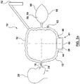
- FIG 1 illustrates an exemplary anesthetic circuit 10 for treating a patient.
- anesthetic circuit 10 comprises a flow passage 12.
- Flow passage 12 provides a passageway for transferring fluid to and from patient 20.
- fluid includes a gas or combination of gases, or a liquid or combination of liquids. Liquids may be present in vapor form, for example. The term fluid may also encompass a mixture of fluids and liquids (which, in some cases, may be in vapor form).
- flow passage 12 provides a hollow conduit.
- Flow passage 12 may be flexible tubing, for example.
- Flow passage 12 may be made of a polymeric material, such as plastic.
- anesthetic circuit 10 may be a ventilation system or, in some cases, operable in conjunction with a ventilation system.
- Anesthetic circuit 10 comprises at least one fluid port 24.
- the at least one fluid port 24 is in fluid communication with flow passage 12 for providing at least external anesthetic agent 16 to patient 20.
- External anesthetic agent 16 will initially anesthetize patient 20, when the anesthetic process commences by delivery of external anesthetic agent 16 to the airway of patient 20, via the at least one fluid port 24.
- the at least one fluid port 24 comprises exit outlet 22 and entry inlet 36. Exit outlet 22 may be configured to be directly received by the airway of patient 20, for delivery of fluid from flow passage 12 to patient 20.
- the at least one fluid port 24 comprises a Y-piece and exit outlet 22 may engage the Y-piece that is received by the airway of patient 20.
- Patient 20 breathes in the external anesthetic agent 16 through his/her airway, thereby delivering the anesthetic agent to the patient's lungs.
- Exhaled fluid mixture 26 comprises exhaled oxygen 28, exhaled carbon dioxide 30 and exhaled anesthetic agent 34.
- Exhaled anesthetic agent 34 may be a molecular anesthetic agent, which may or may not be mixed with other fluids in addition to exhaled oxygen 28 and exhaled carbon dioxide 30.
- molecular anesthetic agents have more than one different atomic element bonded together to form a molecule.
- sevoflurane is a molecular anesthetic agent that has the chemical form (1,1,1,3,3,3-hexafluoro-2-(fluoromethoxy)propane).
- sevoflurane comprises different elements fluorine, carbon and oxygen bonded together.
- noble gases consist of only one atomic element that is not bonded to other atomic elements.
- Exhaled anesthetic agent 34 may originate from external anesthetic agent 16 and may comprise a molecular anesthetic agent.
- exhaled anesthetic agent 34 is a molecular anesthetic agent that was solved in the patient's body (i.e. after cardiac surgery).
- exhaled anesthetic agent 34 comprises a molecular anesthetic agent that was partially solved in the patient's body, and partially contained in external anesthetic agent 16 that was introduced to the patient's airway.
- exhaled molecular anesthetic agent 34 is the only exhaled anesthetic agent. In some embodiments, exhaled anesthetic agent 34 comprises molecular anesthetic agent mixed with other non-molecular anesthetic agents.
- exhaled anesthetic agent 34 comprises a polyhalogenated ether.
- Exhaled anesthetic agent 34 may be hydrophobic (i.e. in gaseous form it dissolves in oil better than water, and in liquid form it is freely miscible with water).
- Non-limiting examples of exhaled anesthetic agent 34 include: sevoflurane, desflurane or isoflurane.
- Exhaled anesthetic agent 34 may be entirely comprised of one of sevoflurane, desflurane or isoflurane, or a mixture thereof.
- Exhaled anesthetic agent 34 may be a volatile anesthetic. Volatile anesthetics are liquid at room temperature (optionally 20°C at 1 atm), but readily evaporate under reduced pressure. Optionally, exhaled anesthetic agent 34 has a vapor pressure at 20°C of between approximately 155 mmHg and 670 mmHg. Optionally, exhaled anesthetic agent 34 has a vapor pressure at 20°C of between approximately 250 mmHg and 500mmHg.
- exhaled anesthetic agent 34 has a boiling point at 760mm in the range of approximately 20°C to 60°C.
- exhaled anesthetic agent 34 is a molecular anesthetic agent that has a molecular weight of at least 150 g/mol.
- exhaled anesthetic agent is a molecular anesthetic agent that has a molecular weight of at least 168 g/mol.
- Xenon which is an atomic anesthetic
- the at least one fluid port 24 may comprise an entry inlet 36 for receiving exhaled fluid mixture 26 from patient 20.
- Flow passage 12 may be in fluid communication with entry inlet 36 for receiving exhaled fluid mixture 26 from entry inlet 36.
- Entry inlet 36 may be configured to be directly received by the airway of patient 20, for delivery of fluid from patient 20 to flow passage 12.
- Entry inlet 36 may be a one-way valve.
- the at least one fluid port 24 may comprise a Y-piece and entry inlet 36 may engage that Y-piece that is received by the airway of patient 20.
- Entry inlet 36 may be separate and distinct from exit outlet 22, as exemplified in Figure 1 . In these cases, exit outlet 22 is configured to receive modified fluid mixture 42 from membrane 38 and provide modified fluid mixture 42 to patient 20.
- anesthetic inlet 14 is separate and distinct from entry inlet 36 and exit outlet 22.
- Exit outlet 22 may be a one-way valve.
- at least one of entry inlet 36 and exit outlet 22 may function as anesthetic inlet 14.
- Anesthetic inlet 14 may be an injector for liquid anesthetic agents.
- anesthetic circuit 10 comprises a membrane 38 that may comprise at least one polymeric material and is in fluid communication with flow passage 12.
- membrane 38 may be contained within a membrane housing 40.
- membrane 38 may fit into an aperture in a wall of flow passage 12, in the absence of membrane housing 40.
- membrane 38 may be fixedly attached to the remainder of a wall of flow passage 12, or formed integrally therewith. In some cases, membrane 38 spans internally between the walls of flow passage 12.
- membrane 38 is configured to receive exhaled fluid mixture 26 from the at least one fluid port 24.
- the at least one fluid port 24 comprises an entry inlet 36 that is separate from exit outlet 22.
- membrane 38 is located downstream from entry inlet 36. In this embodiment, when the exhaled fluid mixture 26 travels through flow passage 12 and after it contacts the membrane 38, a portion of exhaled fluid mixture 26 passes through membrane 38 and out of flow passage 12, to leave a modified fluid mixture 42 in flow passage 12.
- anesthetic circuit 10 comprises a fluid separation apparatus 41, comprising membrane 38 and membrane housing 40.
- Fluid separation apparatus 41 may be releasably connectable to flow path 12.
- fluid separation apparatus 41 is in the form of a cartridge that is releasably connectable to flow path 12.
- fluid separation apparatus 41 may be removed from the anesthetic circuit and replaced with another fluid separation apparatus 41, if the fluid separation becomes damaged, for example.
- Housing inlet 44 may engage flow passage 12 by way for a fluidly sealed friction fit or a clamp coupling, for example.
- a modified fluid mixture 42 is created within membrane housing 40.
- Modified fluid mixture 42 may exit the membrane housing 40 via housing outlet 46.
- Housing outlet 46 may engage flow passage 12 by way for a fluidly sealed friction fit or a clamp coupling, for example. Once the modified fluid mixture 42 exits the membrane housing 40, it may carry on through flow passage 12.
- Membrane 38 may comprise at least one polymeric material. In some embodiments, membrane 38 is entirely made up of polymeric material. In some embodiments, membrane 38 is entirely made up of only one polymeric material. In some embodiments, membrane 38 comprises a polysiloxane and is thereby a polysiloxane membrane. More specifically, membrane 38 may comprise polydimethyl siloxane and thereby be a polydimethyl membrane. In some embodiments, membrane 38 comprises a halocarbon polymer and is thereby a polyhalocarbon membrane. More specifically, membrane 38 may comprise polymethylpentene and thereby be a polymethylpentene membrane.
- the at least one fluid port 24 is configured to receive the modified fluid mixture from membrane 38 and provide at least modified fluid mixture 42 to patient 20.
- exit outlet 22 is configured to receive modified fluid mixture 42 from membrane 38. In some cases, exit outlet 22 is located downstream from membrane 38. Exit outlet 22 provides at least the modified fluid mixture 42 to patient 20. Entry inlet 36 may be located upstream from membrane 38.
- anesthetic circuit 10 comprises a fluid inlet 50 for introducing external fluid from external fluid source 52 to be added to modified fluid mixture 42 in flow passage 12.
- Fluid inlet 50 may be an independent inlet in fluid communication with flow passage 12.
- anesthetic inlet 14 may also serve as fluid inlet 50, as illustrated in Figure 1 .
- Fluid inlet 50 may allow additional fresh fluid (ex. oxygen or air) to be added to flow passage 12 and provided to patient 20 if needed, if the oxygen level within flow passage 12 falls below an acceptable level to support patient 20.
- Oxygen replenishment may be required if, for example, patient 20 increases his/her metabolic rate. Oxygen replenishment may also be required if significant amounts of oxygen exit the flow passage 12 via membrane 38. It should be noted that it is generally cheaper (per unit volume) to add air or oxygen to flow passage 12 than to add external anesthetic agent 16 to flow passage 12.
- External air source 52 may be a tank containing compressed, pressurized fluid (for example, air) therein.
- fluids may at least partially recirculate through flow passage 12.
- An example fluid flow direction 48 is illustrated in Figure 1 .
- membrane 38 may be located in a portion of flow passage 12 that is external to the portion of flow passage 12 that moves fluid in a circular loop corresponding to fluid flow direction 48. In some cases, membrane 38 may be located in a branch passage of flow passage 12 located between fluid source 52 and the portion of flow passage 12 that moves fluid in a circular loop corresponding to fluid flow direction 48. In some embodiments, membrane 38 may be located in anesthetic machine 18.
- Figure 1a illustrates membrane 38 at an alternative location to the location of membrane 38 in Figure 1 .
- anesthetic circuit 10 comprises an external oxygen source 56 for enriching the external fluid with external oxygen.
- External oxygen source 56 may be a tank containing compressed, pressurized oxygen fluid therein.
- the external oxygen may be delivered through fluid inlet 50.
- anesthetic circuit 10 may comprise at least one flow generator 58 for facilitating flow of exhaled fluid mixture 26 and modified fluid mixture 42 through flow passage 12.
- anesthetic machine 18 may serve as flow generator 58, as is commonly known in the art.
- a plurality of flow generators 58 may be provided.
- a first flow generator may drive the flow of the exhaled fluid mixture 26 and a second flow generator may drive the flow of modified fluid mixture 42.
- Examples of flow generator 58 include a motor, fan, pump or vacuum capable of advancing fluids through flow passage 12.
- flow generator 58 comprises compressible member 59.
- compressible member 59 comprises opposing walls 60. When opposing walls 60 are moved towards one another, a positive driving pressure is created in flow passage 12.
- Opposing walls 60 may be flexible.
- Opposing walls 60 may be manually compressible by a human hand.
- the at least one fluid port 24 includes only one fluid port.
- the one fluid port 24 is in fluid communication with flow passage 12 for providing at least external anesthetic agent 16 to patient 20.
- the one fluid port 24 receives the exhaled fluid mixture from patient 20, and flow passage 12 is in fluid communication with the one fluid port 24 to receive exhaled fluid mixture 26 from the one fluid port 24.
- the one fluid port 24 is configured to receive modified fluid mixture 42 from membrane 38 and provide modified fluid mixture 42 to patient 20.
- membrane housing 40 having a membrane therein 38 may also be located between the remainder of flow passage 12 and flow generator 58.
- flow generator 58 may comprise a compressible chamber 59 having opposing walls 60.
- membrane 38 is located in membrane housing 40.
- Exhaled fluid mixture 26 enters membrane housing 40 via housing inlet 44.
- Membrane housing 40 may direct exhaled fluid mixture 26 into contact with membrane 38, to provide modified fluid mixture 42.
- Modified fluid mixture 42 may pass out of membrane housing 40 for a first time via membrane outlet 46.
- Flow generator 58 may direct modified fluid mixture 42 back into membrane housing 40 into contact with membrane 38 for a second time, then membrane housing 40 may direct modified fluid mixture 42 out of membrane housing 40 via housing inlet 44.
- flow generator 58 comprises a bellow comprising a plunger 61 for generating fluid flow.
- anesthetic circuit 10 comprises a membrane housing 40.
- Membrane housing 40 has a membrane housing inlet 44.
- exhaled fluid mixture 26 enters housing 40 at inlet 44 and contacts membrane 38.
- control valve 63 is in an open position. Once the fluid passes membrane 38 when exhalation is completed, control valve 63 closes and fluid is delivered into injection port 67 to force the modified fluid mixture 42 to change direction and flow back towards membrane housing inlet 44 (which now allows modified fluid mixture 42 to exit membrane housing 40).
- modified fluid mixture 42 moves towards membrane housing inlet 44, it passes by membrane 38 for a second time, thereby further reducing the exhaled carbon dioxide 30 concentration in modified fluid mixture 42.
- the forward and reverse fluid flow increases the contact time between the fluid mixture and membrane 38, thereby increasing the efficiency of the exhaled carbon dioxide extraction (per inhalation/exhalation cycle).
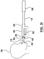
- membrane 38 and membrane housing 40 are located in the vicinity of patient 20's mouth.
- the at least one fluid port 24 includes only one fluid port 24.
- the fluid port provides at least external anesthetic agent 16 to patient 20.
- the fluid port also receives exhaled fluid mixture 26 from patient 20 and directs it toward membrane 38.
- Bellow 60 (or a similar pressure generation device) causes exhaled fluid mixture 26 to pass through membrane 38 twice (in opposite directions), then return to fluid port 24 as modified fluid mixture 42, at which point fluid port 24 receives modified fluid mixture 42 and provides at least modified fluid mixture 42 to patient 20.
- the at least one fluid port 24 comprises only one fluid port 24 and facilitates double fluid flow through membrane 38.
- flow passage 12 is illustrated as a discrete passage that is separate from membrane housing 40 in the figures (see Figures 3f and 3g , for example), it will be appreciated that, in some embodiments, flow passage 12 is not a discrete element and is not separate from membrane housing 40.
- the inside of membrane housing 40 may define the entirety of flow passage 12 and membrane housing 40 (or a small port extending therefrom) may directly engage patient 20's mouth, in the absence of separate flow passage tubing.
- exhaled fluid mixture 26 passes through membrane 38 a first time to become modified fluid mixture 42.
- Modified fluid mixture 42 passes by membrane 38 for a second time, thereby further reducing the exhaled carbon dioxide 30 concentration in modified fluid mixture 42.
- the forward and reverse fluid flow increases the contact time between the fluid mixture and membrane 38, thereby increasing the efficiency of the exhaled carbon dioxide extraction (per inhalation/exhalation cycle).
- anesthetic circuit 10 may also comprise a turbulence-inducing component 64.
- the turbulence-inducing component 64 creates a turbulent flow of exhaled fluid mixture 26 at membrane 38 to increase contact between exhaled fluid mixture 26 and membrane 38.
- Turbulence-inducing component 64 may be any object placed within flow passage 12, as illustrated in Figure 4 , such that the fluids travelling therethrough are forced to flow around the object.
- turbulence-inducing component 64 may comprise a change in geometry within at least one wall of flow passage 12.
- the change in geometry is abrupt, so as to generate fluid flow eddies within flow passage 12.
- the turbulence-inducing component 64 is optionally located upstream and adjacent to the membrane 38. When membrane 38 is contained in membrane housing 40, turbulence-inducing component 64 may be located upstream and adjacent to the housing inlet 44, as illustrated in Figure 4 . Turbulence-inducing component 64 may also be located within membrane housing 40.
- flow passage 12 may have a non-uniform cross-section throughout its length so as to promote turbulent fluid flow through flow passage 12.
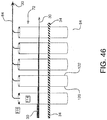
- anesthetic circuit 10 may comprise a plurality of membranes 38. Each membrane 38 may be contained within its own membrane housing 40, as exemplified in Figure 5 .
- membrane 38 is at least partially impervious to the exhaled anesthetic agent 34 to at least partially retain exhaled anesthetic agent 34 in flow passage 12 after the exhaled fluid mixture 26 contacts the membrane 38.
- membrane 38 is substantially impervious to the exhaled anesthetic agent 34 to substantially retain exhaled anesthetic agent 34 in flow passage 12 after the exhaled fluid mixture 26 contacts the membrane 38.
- membrane 38 is substantially impervious to exhaled anesthetic agent 34.
- membrane 38 is configured to permeate less than 5% of the anesthetic agent.
- exhaled anesthetic agent 34 may be an exhaled molecular anesthetic agent.
- membrane 38 is substantially impervious to atomic anesthetic agents (i.e. noble gases, including xenon, for example).
- the separation factor of a membrane is defined as the ratio of the permeability of matter A and permeability of matter B.
- the permeability is equal to Flux divided by Partial Pressure Difference.
- the permeability of a membrane to a specific fluid is therefore a property of the membrane, and not directly linked to the operating conditions.
- a membrane's selectivity of fluid A to fluid B is therefore defined as Permeability A divided by Permeability B.
- Membrane 38 may be pervious to exhaled oxygen 28 such that membrane 38 has an exhaled oxygen-to-exhaled anesthetic agent selectivity of greater than 1. In other words, more exhaled oxygen 28 may leave flow passage 12 through membrane 38 than exhaled anesthetic agent 34. Membrane 38 may be pervious to exhaled oxygen 28 such that membrane 38 has an exhaled oxygen-to-exhaled anesthetic agent selectivity of at least two 2. In other words, at least twice as much exhaled oxygen 28 may leave flow passage 12 through membrane 38 than exhaled anesthetic agent 34.
- membrane 38 may be pervious to exhaled oxygen 28 such that is has an exhaled oxygen-to-exhaled anesthetic agent selectivity of at least 3, 4, 5, 10, 50, 100 or 250.
- exhaled anesthetic agent 34 may be an exhaled molecular anesthetic agent.
- membrane 38 is substantially pervious to exhaled oxygen.
- Membrane 38 is pervious to exhaled carbon dioxide such that membrane 38 has an exhaled carbon dioxide-to-exhaled anesthetic agent selectivity of greater than 1. In other words, more exhaled carbon dioxide 30 leaves flow passage 12 through membrane 38 than exhaled anesthetic agent 34. The membrane is more pervious to exhaled carbon dioxide 30 than exhaled anesthetic agent 34 such that the membrane has an exhaled carbon dioxide-to-exhaled anesthetic agent selectivity of greater than 1. Membrane 38 may be substantially pervious to exhaled carbon dioxide such that membrane 38 has an exhaled carbon dioxide-to-exhaled anesthetic agent selectivity of at least 2.
- exhaled carbon dioxide 30 may leave flow passage 12 through membrane 38 than exhaled anesthetic agent 34.
- membrane 38 may be pervious to exhaled carbon dioxide 30 such that is has an exhaled carbon dioxide-to-exhaled anesthetic agent selectivity of at least 3, 4, 5, 10, 50, 100 or 250.
- exhaled anesthetic agent 34 may be an exhaled molecular anesthetic agent.
- membrane 38 is substantially pervious to exhaled carbon dioxide.
- exhaled anesthetic agent 34 which may be an exhaled molecular anesthetic agent
- exhaled oxygen 28 it is advantageous to at least partially (optionally, substantially) retain exhaled anesthetic agent 34, which may be an exhaled molecular anesthetic agent, while allowing some (optionally, a substantial amount of) exhaled oxygen 28 to pass through membrane 38 and out of anesthetic circuit 10.
- Membranes that have these properties provide some advantages over conventional membranes that have a relatively high (carbon dioxide)/(oxygen) selectivity.
- membranes that allow more exhaled oxygen 28 than anesthetic agent 34 (which may be a molecular anesthetic agent) to pass therethrough are advantageous for use in anesthetic circuit 10.
- exhaled anesthetic agent 34 which may be an exhaled molecular anesthetic agent
- exhaled carbon dioxide 30 is permitted to pass through membrane 38 and out of flow passage 12, this prevents the patient from re-inhaling excessive amounts of exhaled carbon dioxide 30, which could have detrimental health effects.
- anesthetic agent 16 (see Figure 1 ) and exhaled anesthetic agent 34, for the purposes of the present application, pertain to substances that are present in sufficient quantities to have (or at least appreciably contribute to) the anesthetic or desired protective effect on patient 20. Therefore, reference to an anesthetic agent refers to chemicals that are added to the naturally occurring constituents of air.
- external anesthetic agent 16 comprises a mixture of different anesthetic agents and exhaled anesthetic agent 34 comprises a mixture of different anesthetic agents.
- exhaled fluid mixture 26 comprises a metabolic product including acetaldehyde, acetone, ethane, ethylene, hydrogen, isoprene, methane, methylamine or pentane.
- Membrane 38 may be pervious to the metabolic product to permeate the metabolic product through membrane 38, and out of flow passage 12.
- membrane 38 has a metabolic product-to-exhaled anesthetic agent 34 (which may be a molecular anesthetic agent) selectivity of greater than 1.
- exhaled fluid mixture 26 contacts membrane 38 to leave modified fluid mixture 42 in the flow passage having a lower amount of the metabolic product than exhaled fluid mixture 26.
- a membrane comprises at least one hollow fiber.
- a membrane comprises a plurality of hollow fibers.
- the membrane may consist entirely of a plurality of hollow fibers.
- the hollow fibers may comprise polymeric material.
- the hollow fibers may consist entirely of polymeric material.
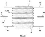
- a membrane comprises a plurality of hollow fibers spaced from one another and adaptable to be substantially parallel to an entry direction of an exhaled fluid mixture when the exhaled fluid mixture initially contacts the plurality of hollow fibers.
- a membrane comprises a plurality of hollow fibers spaced from one another and adaptable to be substantially perpendicular to an entry direction of exhaled fluid mixture when the exhaled fluid mixture initially contacts the plurality of hollow fibers.
- Membrane 38 may be used in an anesthetic circuit, such as anesthetic circuit 10 shown in Figure 1 , for example.
- Figure 9 exemplifies membrane 38 comprising hollow fibers 72 spaced from one another and substantially perpendicular to the entry direction 70 of exhaled fluid mixture 26.
- membrane 38 may be at least partially contained within membrane housing 40.
- hollow fibers 72 are oriented at an angle other than perpendicular or parallel to entry direction 70 of the exhaled fluid mixture.
- Carbon dioxide absorbing material 66 absorbs exhaled carbon dioxide 30 from flow passage 12 and decreases the amount of exhaled carbon dioxide 30 that is re-introduced to patient 20. As exemplified in Figures 10 and 11 , carbon dioxide absorbing material 66 is located on a side of membrane 38 that is external to flow passage 12. Membrane 38 separates carbon dioxide absorbing material 66 from exhaled anesthetic agent 34 (which may be exhaled molecular anesthetic agent) retained in flow passage 12 to impede the exhaled anesthetic agent 34 from contacting the carbon dioxide absorbing material 66.
- exhaled anesthetic agent 34 which may be exhaled molecular anesthetic agent
- membrane 38 selectively allows more exhaled carbon dioxide 30 to pass therethrough than exhaled anesthetic agent 34 (which may be an exhaled molecular anesthetic agent), these harmful reactions are minimized, while still effectively absorbing and extracting the exhaled carbon dioxide 30 out of flow passage 12.
- Figure 12 exemplifies an oxygenator similar in its basic operation to a QUADROX-DTM oxygenator comprising a membrane housing 40 having a blood inlet 76 and a blood outlet 78.
- blood enters membrane housing 40 via blood inlet 76, passes through the membrane in the housing, and exits the membrane housing 40 via blood outlet 78 in a modified form.
- the modified blood exits with a higher oxygen concentration and a lower carbon dioxide concentration.
- blood inlet 76 functions as housing inlet 44.
- exhaled fluid mixture 26 enters membrane housing 40 via housing inlet 44.
- blood outlet 78 functions as housing outlet 46.
- modified fluid mixture 42 exits the membrane housing 40 via housing outlet 46.
- the blood inlet 76 and the blood outlet 78 function as the inlet and outlet for the sweep fluid 84.
- sweep inlet 80 and sweep outlet 82 function as housing inlet 44 and housing outlet 46, respectively.
- the oxygenator similar in its basic operation to QUADROX-DTM has been rotated by 90° relative to the oxygenator exemplified in Figure 12 .
- sweep inlet 80 and sweep outlet 82 engage flow passage 12.
- Exhaled fluid mixture 26 contacts the membrane in Figure 13 ) within the membrane housing 40 such that exhaled fluid mixture 26 is converted to modified fluid mixture 42.
- Tests #5-8 were also conducted in which a QUADROX-DTM oxygenator was used in an anesthetic circuit 10 having one ( Figure 2 ), two, three and four membrane(s) 38 ( Figure 5 ).
- membrane 38 (within the QUADROX-DTM oxygenator) was the OXYPLUSTM membrane.
- an OXYPLUSTM 90/200 membrane having hollow fibers 72 with an outer diameter of 380 micrometers and a dense layer 83 having a thickness of less than 1 micrometer was used.
- membrane housing 40 resembled the configuration described above for Figure 9 .
- the exhaled fluid mixture 26 contacted the outer surface of a hollow fiber 72
- the exhaled oxygen 28 and exhaled carbon dioxide 30 selectively entered the hollow interior of at least one hollow fiber 72.
- the components (or portion thereof) that entered the interior of a hollow fiber 72 then passed through membrane 38 out of the flow passage 12 via at least one end of the hollow fibers 72.
- the portion of the exhaled fluid mixture 26 that remained exterior to the hollow fibers 72 passed around the membrane 38 as modified fluid mixture 42.
- sweep fluid 84 passed through the interior hollow fibers 72 to measure the amount of exhaled oxygen 28, exhaled carbon dioxide 30 and exhaled molecular anesthetic agent 34 in modified fluid mixture 42 that passed into hollow fibers 72.
- concentrations in the exhaled fluid mixture 26 were: 2% exhaled anesthetic agent 34 in oxygen and 4.8% exhaled carbon dioxide 30 in 94% exhaled oxygen 28.
- the flows were 0.8 L/min for sweep fluid 84 (see Figure 13 ) and 2.0 L/min for the exhaled fluid mixture 26.
- the concentrations in the exiting sweep fluid stream were measured using a patient monitor and a quadruple mass spectrometer.
- Figure 19 exemplifies a single hollow fiber 72 of the plurality of hollow fibers 72 shown in Figure 9 , for example.
- Exterior area 116 is separated from the inner lumen 114 of hollow fiber 72 by an outer wall 118.
- Outer wall 118 has a first side 120 that contacts exhaled fluid mixture 26 and permits at least a portion of exhaled carbon dioxide 30 to flow into hollow fiber 72.
- Exterior area 116 may be contained in membrane housing 40 (see membrane housing 40 in Figure 1 , for example).
- Outer wall 118 has a second side 122 that opposes first side 120.
- Modified fluid mixture 42 (with a reduced concetration of exhaled carbon dixoide 30) is provided after at least a portion of exhaled carbon dioxide 30 flows into hollow fiber 72.
- Hollow fiber 72 may permit a sweep fluid 84 to pass therethrough, to facilitate the transport of at least a portion of exhaled carbon dioxide 30 to travel though outer wall 118 into hollow fiber 72. Hollow fibers 72 may direct the exhaled carbon dioxide 30 out of the flow passage 12.
- a sweep fluid 84 may enter the hollow fiber 72 at the sweep inlet 80 and may carry any permeates, like exhaled carbon dioxide 30, out of the hollow fiber 72 via sweep outlet 82.
- membrane 38 is configured such that secondary oxygen in sweep fluid 84 passes through membrane 38 and into flow passage 12.
- Sweep fluid 84 may be substantially pure oxygen or air, for example.
- parameters of the membrane that may be altered include a lower thickness of the membrane, lower density of the membrane, changes in diameter of the hollow fiber, different polymerization of the membrane material resulting in less or more free volume, and/or a more rubbery or more glassy state of the membrane material.
- a shorter length of hollow fibers may limit the accumulation of exhaled carbon dioxide in the sweep fluid inside the hollow fiber and therefore maintain a higher partial pressure gradient for exhaled carbon dioxide and therefore better transport of exhaled carbon dioxide through the membrane.
- planar mat 124 comprises parallel hollow fibers 72 with a spacing 126 between each hollow fiber. In some embodiments, spacing 126 is equal throughout planar mat 124.
- the planar mat shown in Figure 20 comprises warp thread 128 used to space hollow fibers 72 from each other. Warp thread 128 may be woven perpendicular to each hollow fiber 72. Warp thread 128, like hollow fibers 72, may be made of a polymeric material.
- Altering the spacing of the membrane mat layers may introduce a more even flow pattern and evenly distributed carbon dioxide concentration and may, therefore, increase the average exhaled carbon dioxide transport from the exhaled fluid mixture through the membrane.
- membrane 38 may comprise planar mat 124, or a series of planar mats 124, stacked with each other.
- the hollow fibers 72 of each stacked planar mat 124 may be aligned to provide a plurality of parallal or perpendicular hollow fibers 72, as shown in Figures 8 and 9 , respectively.
- planar mats 124 may be stacked such that the orientations of the hollow fibers vary from one planar mat relative to another.
- hollow fibers 72 may be formed in a planar mat 124 wherein the hollow fibers in the same planar mat 124 are arranged at different angles to one another. In some embodiments, at least some of hollow fibers 72 in a planar mat 124 are arranged so that they are not parallel or perpendicular to entry direction 70 of exhaled fluid mixture 26 (see Figures 8 and 9 for entry direction 70). In some embodiments, all of hollow fibers 72 are arranged at an angle other than 0° or 90° relative to entry direction 70.
- a membrane 38 in another embodiment of this disclosure, comprises a plurality of hollow fibers 72 wound into a cylindrical roll 130 defining a hollow inner core 134 having an open end 150 to receive exhaled fluid mixture 26 therein.
- Cylindrical roll 130 may have a closed end 152, comprising a snap-fit cap or plug, for example.
- membrane 38 is configured to direct exhaled fluid mixture 26 radially outwardly from hollow inner core 134. As exhaled fluid mixture 26 travels radially outwardly, it contacts the plurality of hollow fibers 72 of membrane 38, to thereby convert exhaled fluid mixture 26 to modified fluid mixture 42.
- Figure 21b illustrates a cut-away view along line A-A in Figure 21a .
- Figures 21a and 21b illustrate cylindrical roll 130 as a solid body for ease of illustration, it will be appreciated that the cylindrical roll 130 exemplified in Figures 21a and 21b is made up of a plurality of hollow fibers 72.
- relatively long hollow fibers are wrapped or spun around a spool (in a "yarn-like" manner, for example), and cross-wound with one another.
- a plurality of hollow fibers may be randomly arranged into a cylindrical roll 130.
- a membrane in another embodiment of this disclosure, comprises a first planar mat rolled together in a cylindrical roll forming concentric layers of substantially parallel hollow fibers. Conversely, if the hollow fibers in the planar mat are angularly oriented to one another, the concentric layers of the hollow fibers are randomly arranged relative to one another.
- rolled first planar mat defines a hollow inner core having a first open end to receive exhaled fluid and a closed second end.
- Membrane 38 may comprise a rolled planar mat 124.
- Figures 21 and 22 exemplify single hollow fibers 72 or hollow fiber mats 124 (see Figure 20 ) arranged as a cylindrical roll 130 with the hollow fibers 72 having a spacing between the fibers 126 and a layer spacing 132.
- the plurality of hollow fibers 72 in planar mat 124 may be spaced from and substantially parallel with one another.
- the planar mat 124 may be rolled together in a cylindrical roll 130 forming concentric layers of substantially parallel hollow fibers 72.
- hollow fibers 72 may be angled relative to one another.
- planar mat 124 defines a hollow inner core 134 along the longitudinal axis of cylindrical roll 130.
- exhaled fluid mixture 26 flows radially outwardly through wall thickness 136 to provide modified fluid mixture 42.
- a membrane has a portion of the plurality of hollow fibers formed in a second planar mat.
- the plurality of hollow fibers in the second planar mat are spaced from and substantially parallel with one another.
- the first planar mat is overlapped with the second planar mat.
- the plurality of hollow fibers are formed in a first planar mat and a second planar mat.
- the overlapped first and second planar mats are rolled together in a cylindrical roll forming concentric layers of the hollow fibers.
- the first planar mat is overlapped with the second planar mat so that the hollow fibers of the first planar mat are oriented at an angle to the hollow fibers of the second planar mat to provide concentric layers of cross wound hollow fibers.
- the rolled first planar mat and second planar mat may define a hollow inner core having a first open end configured to receive the exhaled fluid mixture and a closed second end.
- Membrane 38 may comprise a plurality of planar mats which overlap one another to form cross wound hollow fibers 72.
- the plurality of hollow fibers 72 may be formed in first planar mat 124 and second planar mat 140.
- a first planar mat 124 (as shown in Figure 19 )
- a second planar mat 140 which is similar to planar mat 124, is rolled onto temporary bobbin 142.
- the plurality of hollow fibers 72 in the first planar mat 124 are spaced from and substantially parallel with each other.
- the plurality of hollow fibers 72 is second planar mat 140 are spaced from and substantially parallel with each other.
- the spacing 126 between all hollow fibers 72 in the same planar mat is substantially the same.
- Each of the first planar mat 124 and second planar mat 140 are unwound from their respective temporary bobbins 138 and 142 and each pulled into trapezoidal shapes defined between hollow fibers 72 and warp thread 128 to overlap the first planar mat 124 and the second planar mat 140 with one another as they are unwound (see Figure 24 ).
- the first planar mat 124 may be overlapped with the second planar mat 140 so that the hollow fibers 72 of first planar mat 124 are oriented at an angle 144 to hollow fibers 72 of second planar mat 140.
- a cross wound roll 146 is formed, and may be rolled onto temporary bobbin 148 for transport or storage. Once temporarily bobbin 148 is removed, a hollow inner core 134 (in the form of a void) is provided in cross wound roll 146. In turn, cross wound roll 146 is provided which may be used as membrane 38.
- angle 144 in Figure 24 may be zero, in which case all of the hollow fibers 72 of first planar mat 124 and second planar mat 140 are substantially parallel to one another.
- membrane 38 comprises multiple rolled planar mats, but otherwise appears similar to cylindrical roll 130 shown in Figures 21 and 22 .
- Figure 26 exemplifies flow separation apparatus 41 comprising membrane 38 in the form of cylindrical roll 130 of Figures 21 and 22 or cross wound roll 146 of Figure 25 within exemplary membrane housing 40.
- flow separation apparatus 41 is releasably connectable to an anesthetic circuit.
- fluid separation apparatus 41 is in the form of a cartridge that is releasably connectable to flow path 12.
- membrane housing 40 has housing inlet 44 and housing outlet 46 located concentrically relative to one another. The exhaled fluid mixture 26 enters housing 40 through housing inlet 44.
- hollow inner core 134 of roll 130 or 146 has a first open end 150 configured to receive exhaled fluid mixture 26, and a closed second end 152.
- exhaled fluid mixture 26 contacts outer wall 118 of at least some of hollow fibers 72 (see Figure 19 for an example hollow fiber 72).
- exhaled carbon dioxide 30 is extracted from exhaled fluid mixture 26 into hollow fibers 72.
- Sweep fluid 84 enters membrane housing 40 through sweep inlet 80. At the same time that exhaled fluid mixture 26 passes along the outer surfaces of hollow fibers 72, sweep fluid 84 passes through the inner lumen 114 (see Figure 19 ) of hollow fibers 72, thereby extracting exhaled carbon dioxide 30 from exhaled fluid mixture 26. Sweep fluid 84, enriched with exhaled carbon dioxide 30, then exits membrane housing 40 via sweep outlet 82.
- exhaled fluid enters membrane housing 40 as exhaled fluid mixture 26 during patient inhalation, and exits membrane housing 40 as modified fluid mixture 42 via the same membrane housing inlet 44.
- membrane housing inlet 44 and membrane housing outlet 46 are separate and concentric with one another.
- Exhaled fluid mixture 26 entered the housing as a fluid comprising 93% oxygen, 4.8% carbon dioxide and 2.2% other partitions that leaked in from the air.
- Sweep fluid 84 entered the housing as 100% oxygen.
- Exhaled fluid mixture 26 contacted hollow fibers 72 to extract exhaled carbon dioxide 30 from exhaled fluid mixture 26 to form modified fluid mixture 42.
- the data shows that modified fluid mixture 42 had a lower percentage of carbon dioxide than exhaled fluid mixture 26.
- Exhaled fluid mixture 26 passed around the exterior of the hollow fibers from hollow inner core 134 to an opposing, exterior side of hollow fibers 72 (i.e. membrane 38) to form modified fluid mixture 42.
- the extraction process was dependent on the flow rate (measured in liters per minute) of exhaled fluid mixture 26 when it contacted hollow fibers 72 and of sweep fluid 84 flowing though the inside of hollow fibers 72.
- Table 6 shows the relative concentration percentages (by volume) of carbon dioxide and oxygen in sweep fluid 84 after exhaled fluid mixture 26 was treated by membrane 38. As shown in Table 6, when exhaled fluid mixture 26 flowed around the exterior of hollow fibers 72, at least some of exhaled carbon dioxide 30 in exhaled fluid mixture 26 flowed into hollow fibers 72 and out of flow passage 12 (i.e. out of the modified fluid mixture 42 that flowed around hollow fibers 72).
- Tables 5 and 6 show that hollow fibers 72 extracted exhaled carbon dioxide 30 from exhaled fluid mixture 26, to form modified fluid mixture 42.
- a membrane comprises a plurality of hollow fibers formed in planar discs vertically stacked upon one another.
- the hollow fibers in each planar disc may be spaced from one another and oriented substantially parallel to one another in a corresponding disc direction.
- the corresponding disc direction for a first disc is different than the corresponding disc direction for any other disc stacked directly adjacent to the first disc.
- the corresponding disc direction for all of the stacked discs may be substantially the same.
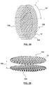
- membrane 38 comprises a plurality of hollow fibers 72 formed in planar discs 154 stacked upon one another.
- the planar discs may be cut from planar mats similar to the planar mat discussed with reference to Figure 20 . As illustrated in Figures 28 and 29 , each planar mat may be cut to define a mat having a rounded perimeter.
- planar discs 154 have a circular shape. In other embodiments, planar discs 154 have an elliptical shape.
- Planar discs 154 may be stacked with a defined vertical disc spacing distance 156 between each disk. In some embodiments, vertical spacing distance 156 is zero, and the stacked planar discs 154 are in direct contact with one another. In some cases, the spacing 126 between all hollow fibers 72 in the same planar disc 154 is equal.
- hollow fibers 72 in each planar disc are spaced from one another and oriented substantially parallel to one another in a corresponding disc direction.
- the corresponding direction of a first of planar discs 154 is different than the corresponding disc direction for any other planar disc directly adjacent to the first of planar discs 154.
- the corresponding disc directions for all of the stacked planar discs 154 may be substantially the same, in which case all of the hollow fibers 72 are substantially in parallel.
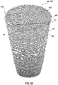
- Hollow fiber discs 154 may be stacked to result in a membrane 38 in the form of stacked cylinder 158, as shown in Figure 30 .
- stacked cylinder 158 contains approximately 175 to 225 planar disks 154.
- Each planar disk 154 may be glued to any planar disc directly above or below it.
- the glue may be placed on each planar disc 154 in a radial manner, so as to define a gas impermeable glue line 160 that defines a cylindrical channel 162 located radially inwardly of glue line 160. Cylindrical channel 162 may be configured to receive exhaled fluid mixture 26.
- FIG 31 illustrates an example membrane housing 40 for housing stacked cylinder 158, as discussed above with reference to Figure 30 .
- Stacked cylinder 158 may be glued to either end cap of the housing 40 via glue line 160 to form a fluid separation apparatus 41.
- membrane housing 40 has sweep inlet 80, sweep outlet 82, membrane housing inlet 44 and a membrane housing outlet 46.
- the space between the outer wall of membrane housing 40 and stacked cylinder 158 may be divided into two symmetrical compartments by two baffles 164. Sweep inlet 80 and sweep inlet 82 may be each located in a respective one of the two symmetrical volumes created by baffles 164.
- membrane outlet 46 is at the same end of membrane housing 40 as sweep inlet 80 and sweep outlet 82, between the sweep inlet and sweep outlet.
- Figure 32 shows a cut-away view through fluid separation apparatus 41 comprising a membrane housing 40.
- fluid separation apparatus 41 is releasably connectable to an anesthetic circuit.
- fluid separation apparatus 41 is in the form of a cartridge that is releasably connectable to flow path 12.
- Exhaled fluid mixture 26 enters membrane housing 40 via membrane housing inlet 44.
- the resulting modified fluid mixture 42 that flows past at least some of hollow fibers 72 has a reduced concentration of exhaled carbon dioxide 30.
- Figure 32 exemplifies housing outlet 46 at the same end of membrane housing 40 as membrane housing inlet 44.
- Sweep fluid 84 enters membrane housing 40 through sweep inlet 80.
- exhaled fluid mixture 26 passes though cylindrical channel 162 of stacked cylinder 158 and around at least some of hollow fibers 72 of stacked cylinder 158, exhaled carbon dioxide 30 is transported through outer wall 118 (see Figure 19 ) of hollow fibers 72, and out of flow passage 12 via hollow fibers 72.
- Sweep fluid 84, enriched with exhaled carbon dioxide 30, then exits membrane housing 40 via sweep outlet 82.
- a membrane exemplified in Figure 33 , is located in an elongate channel having a longitudinal centerline.
- the elongate channel is elongated about the longitudinal centerline.
- the plurality of hollow fibers are arranged substantially perpendicular to the longitudinal centerline of the channel.
- the elongate channel has a rounded cross-section in a plane perpendicular to the longitudinal centerline.
- the elongate channel has a cross-section in a plane perpendicular to the longitudinal centerline and having a cross-sectional area of approximately 300 mm 2 to 20,000 mm 2 .
- the longitudinal centerline may be curved.
- FIG. 33 exemplifies a membrane that may be used as membrane 38.
- the plurality of hollow fibers 72 of membrane 38 is located in membrane housing 40 to form a fluid separation apparatus 41.
- Membrane housing 40 is an elongate channel 166 having a longitudinal centerline 168.
- Elongate channel 166 is elongated about longitudinal centerline 168.
- the plurality of hollow fibers 72 may be arranged substantially perpendicular to longitudinal centerline 168.
- hollow fibers 72 may be oriented at an angle other than 90° or 0° relative to longitudinal centerline 168. In these cases, exhaled fluid mixture 26 flows around hollow fibers 72, to remove exhaled carbon dioxide 30 from exhaled fluid mixture 26.
- elongate channel 166 may have a substantially rectangular cross-section in a plane perpendicular to the longitudinal centerline 168.
- elongate channel 166 may have a rounded cross-section in a plane perpendicular to longitudinal centerline 168.
- elongate channel 166 may have a circular, oval, or elliptical cross-section. In other cases, elongate channel 166 may have curved edges.
- Elongate channel 166 may have a cross-sectional area (in a plane perpendicular to longitudinal centerline 168) of approximately 300 mm 2 to 20,000 mm 2 .
- Figures 33 , 34 and 35 show housing inlet 44 and housing outlet 46 at opposite ends of elongate channel 166.
- exhaled fluid mixture 26/modified fluid mixture 42 flow once past membrane 38.
- housing inlet 44 and housing outlet 46 are located at the same end of elongated channel 166, to facilitate bi-directional (double) fluid flow across hollow fibers 72 of membrane 38.
- elongate channel 166 has a curved longitudinal centerline 168.
- Figure 36 exemplifies a fluid separation apparatus 41 comprising a continuous elongate channel 166 disposed in membrane housing 40 and arranged in a spiral pattern.
- membrane housing 40 has a membrane housing inlet 44.
- exhaled fluid mixture 26 enters housing 40 at membrane housing inlet 44 and travels in a direction parallel to longitudinal centerline 168 of channel 166.
- exhaled fluid mixture 26 passes over hollow fibers 72 (shown in Figures 34 and 35 )
- exhaled carbon dioxide 30 is extracted to provide modified fluid mixture 42.
- valve 170 is in an open position.
- valve 170 closes and external fluid enters elongate channel 166 via injection port 172 (which may be near valve 170) to force the modified fluid mixture 42 to change direction and flow back towards membrane housing inlet 44 (which now functions to allow modified fluid mixture 42 to exit membrane housing 40).
- injection port 172 which may be near valve 170
- modified fluid mixture 42 moves towards membrane housing inlet 44 after it passes by hollow fibers 72 for a second time, it further reduces the exhaled carbon dioxide concentration in modified fluid mixture 42.
- the forward and reverse fluid flow increases the contact time between the fluid mixture and the hollow fiber membranes, thereby increasing the efficiency of the exhaled carbon dioxide extraction (per inhalation/exhalation cycle).
- the elongate channel 116 in conjunction with injection port 172, may act as the flow generator to promote fluid movement through elongate channel 116 and, in some cases through other portions of flow passage 12 (see flow passage 12 in Figure 1 , for example).
- a membrane exemplified in Figure 37 , is located in a housing and at least one hollow fiber of the membrane has a corresponding shape and orientation that is different than the corresponding shape and orientation of another hollow fiber.
- each hollow fiber has a corresponding shape and orientation that is different than a corresponding shape and orientation of all other hollow fibers in the housing.
- Figure 37 illustrates a further embodiment for fluid separation apparatus 41 comprising membrane 38 and membrane housing 40, wherein membrane 38 comprises a plurality of hollow fibers 72 in membrane housing 40.
- membrane 38 comprises a plurality of hollow fibers 72 in membrane housing 40.
- at least one hollow fiber 72 has a corresponding shape and orientation that is different than a corresponding shape and orientation of another hollow fiber.
- each hollow fiber has a corresponding shape and orientation that is different than a corresponding shape and orientation of all other hollow fibers in membrane housing 40.
- Each hollow fiber 72 may have a curved shape and angular orientation relative to membrane housing 40 that is different than the curved shape and angular orientation of all other hollow fibers 72 in the membrane housing 40.
- hollow membranes 72 may be randomly packed (randomly oriented) into membrane housing 40 in a "spaghetti noodle-like" manner.
- the amount of hollow fibers 72 used per volume of space within membrane housing 40 defines the resistance for the exhaled fluid mixture 26 passing through from membrane housing inlet 44 to membrane housing outlet 46.
- a sweep fluid 84 travels through inner lumen 114 in hollow fibers 72 (see Figure 19 ) to facilitate the removal of exhaled carbon dioxide from exhaled fluid mixture 26 introduced into membrane housing 40.
- Each of the embodiments of membrane 38 described above may be located in a membrane housing 40 within an anesthetic circuit 10 having a membrane housing inlet 44 and a membrane housing outlet 46.
- exhaled anesthetic fluid 26 enters membrane housing 40 via membrane housing inlet 44, flows once through membrane 38, then exits membrane housing 40 via membrane housing outlet 46 as modified fluid mixture 42.
- Figures 26 and 32 show membrane housing inlet 44 and membrane housing outlet 46 located at the same end of the membrane housing 40.
- Figures 26 and 32 are applicable to anesthetic circuits 10 similar to those illustrated in Figures 1 , 2 , 3a , 4 , 5 , 6 and 7 , for example, when slightly modified.
- Figure 38 illustrates the anesthetic circuit of Figure 1 , slightly modified to have housing outlet inlet 44 and housing outlet 46 on the same side of membrane housing 40.
- Anesthetic circuit 10, as shown in Figure 1 for example has exit outlet 22 and entry inlet 36.
- entry inlet 36 and exit outlet 22 may be different openings in flow passage 12.
- a further disclosure not claimed comprises a method for anesthetic treatment of a patient.
- the method comprises introducing an external anesthetic agent 16 towards and into a patient via flow passage 12.
- External anesthetic agent 16 may be stored in anesthetic machine 18 or another external source. This anesthetic agent is delivered to patient 20, through flow passage 12.
- the external anesthetic agent 16 travels to the patient's lungs.
- the patient's lungs produce an exhaled fluid mixture 26, which is expelled from the airway of patient 20 as he/she exhales. Exhaled fluid mixture 26 is then directed away from and out of patient 20 into flow passage 12.
- Exhaled fluid mixture 26 from the patient 20 comprises exhaled oxygen 28, exhaled carbon dioxide 30 and exhaled anesthetic agent 34.
- Exhaled fluid mixture 26 is advanced through flow passage 12 towards and into contact with membrane 38 comprising a plurality of hollow fibers in fluid communication with the flow passage. More of exhaled carbon dioxide 30 than exhaled anesthetic agent 34 is transferred out of the flow passage after exhaled fluid mixture 26 contacts membrane 38 to leave modified fluid mixture 42 in flow passage 12.
- Modified fluid mixture 42 has a lower concentration of exhaled carbon dioxide 30 than exhaled fluid mixture 26.
- Modified fluid mixture 42 is advanced through flow passage 12 toward patient 20 to provide at least modified fluid mixture 42 to patient 20.
- Exhaled anesthetic agent 34 may be an exhaled molecular anesthetic agent.
- Fluid separation apparatus 41 is fluidly connectable to an anesthetic circuit (such as anesthetic circuit 10 shown in Figure 1 , for example).
- anesthetic circuit 10 has flow passage 12 for transporting exhaled fluid mixture 26 containing at least exhaled anesthetic agent 34 and exhaled carbon dioxide 30 through flow passage 12.
- fluid separation apparatus 41 is releasably connectable with flow passage 12 of anesthetic circuit 10.
- fluid separation apparatus 41 is a cartridge releasably connectable with flow passage 12 of anesthetic circuit 10.
- fluid separation apparatus 41 is configured to receive exhaled fluid mixture 26 via housing inlet 44.
- exhaled fluid mixture 26 may flow into hollow inner core 134.
- the fluid pressure in inner core 134 is increased as flow continues.
- Closed second end 152 facilitates this increase in pressure, since exhaled fluid mixture 26 cannot escape hollow inner core 134 via closed second end 152.
- Closed second end 152 may be a plug or snug-fit cap, for example.
- closed second end 152 may be integrally formed in membrane housing 40.
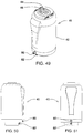
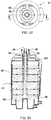
- Figure 52 shows a top view of fluid separation apparatus 41 of Figures 49 to 51 .
- Figure 53 shows a cut-away side view along line A-A in Figure 52.
- Figure 53 shows the flow of exhaled fluid mixture 26 from membrane housing inlet 44, through membrane 38; and modified fluid mixture 42 out of membrane housing outlet 46 in a similar manner to that illustrated for the fluid separation apparatus of Figure 44 .
- exhaled fluid mixture 26 / modified fluid mixture 42 may flow in the opposite direction to that shown in Figure 53 .
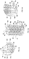
- FIG 54 exemplifies a flow path of sweep fluid 84 through the fluid separation apparatus of Figures 49 to 53 .
- Membrane housing 40 is configured to direct sweep gas 84 received from sweep inlet 80 through a first portion 176 of the plurality of hollow fibers 72 in a first sweep direction and subsequently through a second portion 178 of the plurality of hollow fibers 72 in a second sweep direction substantially opposite to the first sweep direction before sweep gas 84 exits membrane housing 40 via sweep outlet 82.
- first portion 176 of the plurality of hollow fibers 72 is radially outward of second portion 178 of the plurality of hollow fibers 72.
- sweep fluid 84 may enter membrane housing 40 via sweep inlet 80.
- Dividing wall 180 may be configured to direct sweep fluid 84 through membrane 38.
- sweep fluid 84 By recirculating sweep fluid 84 through membrane 38, less sweep fluid is required to run the system. This can result in cost and energy savings.
- the recirculation also makes the extraction of exhaled carbon dioxide from exhaled fluid mixture more efficient.
- the partial pressure and concentration of carbon dioxide in sweep fluid 84 has to be lower than in exhaled fluid mixture 26.
- sweep flow 84 flows through a smaller number of hollow fibers 72 in a first portion 176 of the plurality of hollow fibers 72 than it does as it flows in a subsequent direction through the second portion 178 of hollow fibers 72.
- Figure 54 illustrates a double-flow of sweep fluid through membrane 38
- sweep fluid 84 may flow through membrane 38 more than twice.
- a concentration difference of carbon dioxide is also maintained, in the manner described above, such that sweep fluid 84 has the lowest concentration of carbon dioxide as it flows through a first portion 176 of hollow fibers 72 and then has a higher concentration of carbon dioxide as it flows through subsequent portions of hollows fibers 72.
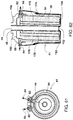
- Figure 61 shows a top view of fluid separation apparatus 41 of Figures 57 to 59 , showing the flow of sweep fluid 84 through fluid separation apparatus 41.
- the flow path of sweep fluid 84 is also illustrated in Figure 62 , which shows a cut-away side view along line B-B in Figure 59 .
- the flow path is substantially the same as that shown in Figure 54 except that sweep gas 84 is received from sweep inlet 80 at an opposing end of membrane housing 40 (as compared to Figure 54 ).
- sweep gas 84 flows through a first portion 176 of the plurality of hollow fibers 72 and subsequently through a second portion 178 of the plurality of hollow fibers 72 in substantially opposite directions to those shown in Figure 54 .
- inner shaft 174 has a first end 186 and a second end 187.
- first end 186 may be located in membrane housing 40 with first end 186 closer to membrane housing inlet 44 than second end 187. Studies showed that this arrangement facilitated more even flow distribution of exhaled fluid mixture 26 into membrane 38 than an arrangement wherein inner shaft 174 has apertures 175 of equal size.
- Tables 7 and 9 show the inspired fraction (Fi [Vol%]) of oxygen, CO 2 , sevoflurane (FiO 2 , FiCO 2 , FiSevo) at the absorber outlet, and the end tidal fraction (et [Vol%]) of oxygen, CO 2 , sevoflurane (etO 2 , etCO 2 , etSevo) in the exhaled fluid mixture.
Landscapes
- Health & Medical Sciences (AREA)
- Engineering & Computer Science (AREA)
- Chemical & Material Sciences (AREA)
- Biomedical Technology (AREA)
- Anesthesiology (AREA)
- Life Sciences & Earth Sciences (AREA)
- Environmental & Geological Engineering (AREA)
- Pulmonology (AREA)
- Veterinary Medicine (AREA)
- Animal Behavior & Ethology (AREA)
- Public Health (AREA)
- General Health & Medical Sciences (AREA)
- Heart & Thoracic Surgery (AREA)
- Hematology (AREA)
- Emergency Medicine (AREA)
- General Chemical & Material Sciences (AREA)
- Oil, Petroleum & Natural Gas (AREA)
- Chemical Kinetics & Catalysis (AREA)
- Analytical Chemistry (AREA)
- Biodiversity & Conservation Biology (AREA)
- Ecology (AREA)
- Environmental Sciences (AREA)
- Separation Using Semi-Permeable Membranes (AREA)
- External Artificial Organs (AREA)
Description
- This invention relates to an esthetic circuit to anesthetize a patient and a fluid separation apparatus connectable to an anesthetic circuit.
- Anesthetic agents are commonly used to anesthetize a patient during a medical procedure. To keep the stress level low and relax the patient, the patient has to be asleep for many medical procedures. Anesthetic circuit systems wherein anesthetic agent is partially re-used after being delivered to the patient are known in the art. The benefit is that less anesthetic agent is used. This is financially beneficial due to the relatively high cost of most anesthetic agents. The use of less anesthetic agents may also be good for the environment since some anesthetic agents, such as the halogenated hydrocarbon sevoflurane, for example, are greenhouse fluids.
- Carbon dioxide is formed in the cell and is released though the alveoli of the lungs during expiration at a level of around 5% of the expiratory fluid mixture. The concentration at the end of expiration is called the end tidal concentration of carbon dioxide (etCO2). The inspiratory level of carbon dioxide is normally below 0.5%. Having excessive levels of carbon dioxide in the blood of the patient will decrease the pH value of the blood (acidosis) and will, if not treated properly, affect the patient's brain activity and may eventually lead to unconsciousness and death.
- When the patient inhales the anesthetic agent in a fluid mixture, the anesthetic agent passes through the alveoli of the lungs into the patient's blood. The patient exhales a fluid mixture comprising, among other components, exhaled anesthetic, exhaled oxygen and exhaled carbon dioxide. Due to the operation of the human's lungs, the carbon dioxide content of the exhaled fluid mixture is higher than that of the inhaled fluid mixture. Furthermore, the oxygen content of the exhaled fluid mixture is lower than that of the inhaled fluid mixture in most cases. To be able to re-use the fluid mixture (containing the exhaled anesthetic fluid), the carbon dioxide of the exhaled fluid mixture must be lowered to levels suitable for re-inhalation.
- Anesthetic circuits aimed at decreasing the amount of carbon dioxide fluid re-inhaled by the patient are known in the art. Some in the industry have focused on decreasing the carbon dioxide content in the exhaled mixture, along with trying to preserve exhaled oxygen and exhaled anesthetic agent within the anesthetic circuit for re-inhalation. Their desire to preserve exhaled oxygen fluid is premised on the notion that oxygen needs to be provided as part of the inhaled mixture in an appropriate level to keep the oxygen saturation in the patient's blood high enough to allow for proper metabolism. Many publications focus on separating or binding the CO2 specifically and therefore separate it from the fluid mixture containing the anesthetic agent.
- Some conventional anesthetic circuits use carbon dioxide absorbers to reduce exhaled carbon dioxide within the anesthetic circuit. In some cases, soda lime or baralyme, for example, are used. Sevoflurane and other anesthetic vapors can react with these carbon dioxide absorbers to produce harmful chemicals such as compound A. Compound A has been found to have negative effects such as nephro and cerebo toxic effects.
- In other conventional systems, a membrane impregnated with a substance that is chemically reactive with carbon dioxide (and, in some cases, anesthetic agent) is used to reduce the amount of exhaled carbon dioxide from an anesthetic circuit. For example, membranes comprising amino acids or amine groups that are chemically reactive with carbon dioxide are known in the art. The reactive sites may degrade or become contaminated over time, which requires the membrane to be disposed of and replaced.
- Specific examples of selective membranes known in the art that separate an anesthetic from at least one other fluid include: United States Patent No.
2007/0017516 to Schmidt , United States Patent Application No.2010/0031961 to Schmidt , United States Patent No.2009/0126733 to Kulkarni et al. and The Journal of Membrane Science Article "Xenon recycling in an anaesthetic closed-system using carbon molecular sieve membranes" (S. Lagorsse, F.D. Magalhães, A. Mendes; Journal of Membrane Science 301 (2007) 29-38). -
- There exists a need for an improved anesthetic circuit in which exhaled anesthetic agent can be effectively retained and re-circulated to the patient.
- The following summary is provided to introduce the reader to the more detailed discussion to follow. The summary is not intended to limit or define the claims. The scope of the invention is as defined by the appended claims.
- According to one broad aspect of this disclosure, an anesthetic circuit for treating a patient is provided. The anesthetic circuit comprises:
- a flow passage;
- an anesthetic agent inlet in fluid communication with the flow passage for introducing an external anesthetic agent into the flow passage;
- at least one fluid port in fluid communication with the flow passage for providing at least the external anesthetic agent to the patient, wherein
- the at least one fluid port receives an exhaled fluid mixture from the patient, the exhaled fluid mixture comprising an exhaled oxygen, an exhaled carbon dioxide and an exhaled anesthetic agent, the flow passage being in fluid communication with the at least one fluid port for receiving the exhaled fluid mixture from the at least one fluid port;
- a membrane comprising a plurality of hollow fibers, the membrane being in fluid communication with the flow passage, configured to receive the exhaled fluid mixture from the at least one fluid port, and at least partially impervious to the exhaled anesthetic agent to at least partially retain the exhaled anesthetic agent in the flow passage after the exhaled fluid mixture contacts the membrane, wherein
- the membrane is pervious to the exhaled carbon dioxide such that the membrane has an exhaled carbon dioxide-to-exhaled anesthetic agent selectivity of greater than 1,
- the exhaled fluid mixture contacts the membrane wherein the membrane separates a portion of the exhaled carbon dioxide from the exhaled fluid mixture to leave a modified fluid mixture in the flow passage having a lower amount of the exhaled carbon dioxide than the exhaled fluid mixture, and
- the at least one fluid port is configured to receive the modified fluid mixture from the membrane and provide at least the modified fluid mixture to the patient; and
- a fluid inlet for introducing an external fluid into the flow passage to be added to the modified fluid mixture provided to the patient.
- In some cases, the exhaled anesthetic agent is an exhaled molecular anesthetic agent. In some embodiments, the membrane comprises at least one polymeric material. In some cases, the membrane is pervious to the exhaled oxygen such that the membrane has an exhaled oxygen-to-exhaled molecular anesthetic agent selectivity of greater than 1.
- In some embodiments, the membrane is pervious to the exhaled oxygen such that the membrane has an exhaled oxygen-to-exhaled anesthetic agent selectivity of at least 2.
- In some cases, the membrane has an exhaled carbon dioxide-to-exhaled anesthetic agent selectivity of at least 2.
- In some embodiments, the membrane is entirely made up of polymeric material.
- In some cases, the membrane is configured such that a secondary oxygen located external to the flow passage passes through the membrane and into the flow passage.
- In some embodiments, the anesthetic circuit further comprises an external oxygen source for enriching the external fluid with external oxygen. In other embodiments, an external oxygen source introduces external oxygen directly into the anesthetic circuit.
- In some cases, the anesthetic circuit further comprises at least one flow generator for facilitating flow of the exhaled fluid mixture and the modified fluid mixture through the flow passage.
- In some embodiments, the anesthetic circuit further comprises a turbulence-inducing component in the flow passage to create a turbulent flow of the exhaled fluid mixture at the membrane to increase contact between the exhaled fluid mixture and the membrane.
- In some cases, the exhaled anesthetic agent is a volatile anesthetic agent and the membrane is at least partially impervious to the volatile anesthetic agent.
- In some embodiments, the exhaled anesthetic agent is a polyhalogenated ether.
- In some cases, the exhaled anesthetic agent includes at least one of sevoflurane, isoflurane or desflurane.
- In some embodiments, the exhaled anesthetic agent has a molecular weight of greater than 168 g/mol.
- In some cases, a carbon dioxide absorbing material is located on a side of the membrane that is external to the flow passage. In some cases, the membrane separates the carbon dioxide absorbing material from the exhaled anesthetic agent retained in the flow passage to impede the exhaled anesthetic agent from contacting the carbon dioxide absorbing material. In some cases, the carbon dioxide absorbing material comprises at least one of: soda lime, alkanolime, alkanolamine, amino compounds, alkali salts of amino acids, glycine, DL-alanine, beta-alanine, serine, threonine, isoleucine, DL-valine, piperazine-2-carboxilic acid, proline, arginine, gamma-aminobutyric acid, ornithine, potassium glycinate, potassium threonate, taurine, creatine and histidine.
- In some embodiments, the anesthetic circuit of the exhaled fluid mixture comprises a metabolic product including acetaldehyde, acetone, ethane, ethylene, hydrogen, isoprene, methane, methylamine or pentane. In some cases, the membrane is pervious to the metabolic product and the exhaled fluid mixture contacts the membrane to leave a modified fluid mixture in the flow passage having a lower amount of the metabolic product than the exhaled fluid mixture.
- In some cases, the membrane is a polyhalocarbon membrane. More specifically, in some cases, the membrane is a polymethylpentene membrane. In some cases, the membrane is a polysiloxane membrane. More specifically, in some cases, the membrane is a polydimethyl siloxane membrane.
- In some embodiments, the membrane is a dense membrane.
- In some cases, the membrane is an asymmetric membrane comprising the plurality of hollow fibers and the plurality of hollow fibers have at least one wall comprising a porous support layer and a dense layer.
- In some embodiments, the membrane comprises a glassy polymer, a polymeric size selective membrane or a composite polymer membrane.
- The membrane is completely inert with respect to the exhaled carbon dioxide and is free of any amino acids.
- In some embodiments, the at least one fluid port comprises an exit outlet in fluid communication with the flow passage for providing at least the external anesthetic agent to the patient and an entry inlet separate from the exit outlet for receiving the exhaled fluid mixture from the patient. The flow passage may be in fluid communication with the entry inlet for receiving the exhaled fluid mixture from the entry inlet. The exit outlet may be configured to receive the modified fluid mixture from the membrane and provide the modified fluid mixture to the patient.
- In some cases, the at least one fluid port includes only one fluid port. The one fluid port may be in fluid communication with the flow passage for providing at least the external anesthetic agent to the patient. The one fluid port may receive the exhaled fluid mixture from the patient. The flow passage may be in fluid communication with the one fluid port for receiving the exhaled fluid mixture from the one fluid port. The one fluid port may be configured to receive the modified fluid mixture from the membrane and provide the modified fluid mixture to the patient.
- In some cases, each hollow fiber has an outer wall having a first side that contacts the exhaled fluid mixture and permits at least a portion of the exhaled carbon dioxide to flow into the hollow fiber, and an opposing second side at which the modified fluid mixture is provided after at least a portion of the exhaled carbon dioxide flows into the hollow fiber.
- In some embodiments, the hollow fibers permit a sweep fluid to pass therethough to facilitate the transport of at least a portion of the exhaled carbon dioxide into the hollow fibers, and the hollow fibers direct the sweep fluid and the exhaled carbon dioxide out of the flow passage.
- In some cases, the membrane is located in a membrane housing. The exhaled fluid mixture may enter the membrane housing via a housing inlet. The membrane housing may direct the exhaled fluid mixture into contact with the membrane, to provide the modified fluid. The membrane housing may direct the modified fluid mixture out of the housing via the housing inlet. Alternatively, the membrane housing may direct the modified fluid mixture out of the housing via a housing outlet.
- In some cases, the housing exit and the housing inlet are separate and concentric with one another.
- In some embodiments, the plurality of hollow fibers are spaced from one another and are arranged substantially parallel to an entry direction of the exhaled fluid mixture when the exhaled fluid mixture initially contacts the plurality of hollow fibers.
- In some cases, the plurality of hollow fibers are spaced from one another and are arranged substantially perpendicular to a flow direction of the exhaled fluid mixture when the exhaled fluid mixture initially contacts the plurality of hollow fibers.
- In some embodiments, the membrane comprises the plurality of hollow fibers wound into a cylindrical roll defining a hollow inner core having an open end to receive the exhaled fluid mixture therein.
- In some embodiments, the plurality of hollow fibers are formed in at least a first planar mat. In some cases, the plurality of hollow fibers in the first planar mat are spaced from and substantially parallel with one another.
- In some cases, the first planar mat is rolled together in a cylindrical roll forming concentric layers of substantially parallel hollow fibers.
- In some embodiments, the rolled first planar mat defines a hollow inner core having a first open end to receive the exhaled fluid mixture and a closed second end.
- In some cases, the plurality of hollow fibers are formed in the first planar mat and second planer mat, , the plurality of hollow fibers in the second planar mat are spaced from and substantially parallel with one another, the first planar mat is overlapped with the second planar mat, and the overlapped first and second planar mats are rolled together in a cylindrical roll forming concentric layers of the hollow fibers.
- In some embodiments, the first planar mat is overlapped with the second planar mat so that the hollow fibers of the first planar mat are oriented at an angle to the hollow fibers of the second planar mat to provide concentric layers of cross wound hollow fibers.
- In some cases, the rolled first planar mat and second planar mat define a hollow inner core having a first open end configured to receive the exhaled fluid mixture.
- In some embodiments, the plurality of hollow fibers are formed in planar discs stacked upon one another, and the hollow fibers in each planar disc are spaced from one another and oriented substantially parallel to one another in a corresponding disc direction.
- In some cases, the corresponding disc direction for a first disc is different than the corresponding disc direction for any other disc stacked directly adjacent to the first disc.
- In some embodiments, the corresponding disc direction for all of the stacked discs is substantially the same.
- In some cases, the plurality of hollow fibers of the membrane are located in an elongate channel having a longitudinal centerline.
- In some embodiments, the plurality of hollow fibers are arranged substantially perpendicular to the longitudinal centerline of the elongate channel.
- In some cases, the elongate channel has a substantially rectangular cross-section in a plane perpendicular to the longitudinal centerline.
- In some embodiments, the elongate channel has a rounded cross-section in a plane perpendicular to the longitudinal centerline.
- In some cases, the elongate channel has a cross-section in a plane perpendicular to the longitudinal centerline having a cross-sectional area of approximately 300 mm2 to 20,000 mm2.
- In some embodiments, the longitudinal centerline of the elongate channel is curved.
- In some embodiments, the plurality of hollow fibers of the membrane are located in a membrane housing, the hollow fibers are randomly packed (randomly oriented) in to the membrane housing.
- In some cases, the exhaled fluid mixture enters the housing via a housing inlet, the membrane housing directs the exhaled fluid mixture into contact with the membrane to provide the modified fluid mixture, and the membrane directs the modified fluid mixture out of the membrane housing via a housing outlet.
- In some cases, the plurality of hollow fibers of the membrane are located in a housing and at least one hollow fiber has a corresponding shape and orientation that is different than a corresponding shape and orientation of another hollow fiber.
- In some cases, each hollow fiber has a corresponding shape and orientation that is different than a corresponding shape and orientation of all other hollow fibers in the housing.
- According to another broad aspect of this disclosure, a fluid separation apparatus fluidly connectable to an anesthetic circuit is provided, the anesthetic circuit having a flow passage for transporting an exhaled fluid mixture containing at least exhaled anesthetic agent and exhaled carbon dioxide through the flow passage. The fluid separation apparatus comprises:
- a membrane having a plurality of hollow fibers, wherein
- the membrane is at least partially impervious to the exhaled anesthetic agent to at least partially retain the exhaled anesthetic agent in the flow passage after the exhaled fluid mixture contacts the membrane, and
- the membrane is more pervious to the exhaled carbon dioxide than the exhaled anesthetic agent such that the membrane has an exhaled carbon dioxide-to-exhaled anesthetic agent selectivity of greater than 1; and
- a membrane housing containing the membrane therein, wherein
- the housing is configured to receive the exhaled fluid mixture via a housing inlet,
- the membrane housing directs the exhaled fluid mixture into contact with the membrane, to provide a modified fluid mixture having a lower amount of the exhaled carbon dioxide than the exhaled fluid mixture,
- the membrane housing directs the modified fluid mixture out of the membrane housing via a housing outlet,
- the at least one hollow fiber permits a sweep fluid to pass therethough to facilitate the transport of at least a portion of the exhaled carbon dioxide into the at least one hollow fiber, and
- the membrane housing has at least one sweep inlet to receive the sweep fluid therethrough and at least one sweep outlet to expel the sweep fluid from the membrane housing.
- In some embodiments, the membrane housing is configured to direct the sweep gas received from the sweep inlet through a first portion of the plurality of hollow fibers in a first sweep direction and subsequently through a second portion of the plurality of hollow fibers in a second sweep direction substantially opposite to the first sweep direction before the sweep gas exists the housing via the sweep outlet. In some cases, the first portion of the plurality of hollow fibers is radially outward of the second portion of the plurality of hollow fibers.
- In some embodiments, the sweep fluid comprises at least nitrogen gas, the membrane is at least partially impervious to the nitrogen gas and pervious to the exhaled carbon dioxide such that the membrane has an exhaled carbon dioxide-to-nitrogen gas selectivity of greater than 1.
- In some cases, the membrane comprises the plurality of hollow fibers wound into a cylindrical roll defining a hollow inner core having an open end to receive the exhaled fluid mixture.
- In some embodiments, the membrane is pervious to a metabolic product in the exhaled fluid mixture and the exhaled fluid mixture contacts the membrane to leave a modified fluid mixture in the flow passage having a lower amount of the metabolic product than in the exhaled fluid mixture. Metabolic products may include acetaldehyde, acetone, ethane, ethylene, hydrogen, isoprene, methane, methylamine or pentane.
- In some cases, the membrane housing comprises an inner shaft inserted into the hollow inner core of the membrane, and the inner shaft has a plurality of apertures therein to direct the exhaled fluid mixture through the apertures and into the membrane. In some cases, the apertures located further away from the membrane housing inlet are generally smaller than the apertures located closer to the membrane housing inlet.
- According to another broad aspect of this disclosure, a method is provided for anesthetic treatment of a patient, the method is not part of the claimed invention. The method comprises:
- introducing an external anesthetic agent towards and into the patient via a flow passage;
- directing an exhaled fluid mixture comprising an exhaled oxygen, an exhaled carbon dioxide and an exhaled anesthetic agent away from and out of the patient into the flow passage;
- advancing the exhaled fluid mixture through the flow passage towards and into contact with a membrane comprising a plurality of hollow fibers in fluid communication with the flow passage;
- transferring more of the exhaled carbon dioxide than the exhaled anesthetic agent from the exhaled fluid mixture through the membrane and out of the flow passage after the exhaled fluid mixture contacts the membrane to leave a modified fluid mixture in the flow passage, wherein the modified fluid mixture has a lower concentration of the exhaled carbon dioxide than the exhaled fluid mixture; and
- advancing the modified fluid mixture through the flow passage toward the patient to provide at least the modified fluid mixture to the patient.
- In some cases, the method for anesthetic treatment of a patient further comprises:
- transferring exhaled oxygen through the membrane after the exhaled fluid mixture contacts the membrane to leave a modified fluid mixture in the flow passage, wherein the membrane has an exhaled oxygen-to-exhaled anesthetic agent selectivity of greater than 1, and wherein
- the external anesthetic agent comprises a molecular anesthetic agent,
- the exhaled anesthetic agent is an exhaled molecular anesthetic agent, and the plurality of hollow fibers are made at least partially of polymeric material.
- advancing the modified fluid mixture through the flow passage toward the patient to provide at least the modified fluid mixture to the patient.
- According to yet another broad aspect of this disclosure, a membrane is provided for selectively separating fluids from an exhaled fluid mixture in an anesthetic circuit, the exhaled fluid mixture containing at least exhaled anesthetic agent and exhaled carbon dioxide. The membrane comprises:
- a plurality of hollow fibers, wherein
- the membrane is at least partially impervious to the exhaled anesthetic agent to at least partially retain the exhaled anesthetic agent in the flow passage after the exhaled fluid mixture contacts the membrane, and
- the membrane is more pervious to the exhaled carbon dioxide than the exhaled anesthetic agent such that the membrane has an exhaled carbon dioxide-to-exhaled anesthetic agent selectivity of greater than 1.
- In some embodiments, the membrane comprises the plurality of hollow fibers wound into a cylindrical roll defining a hollow inner core having an open end to receive the exhaled fluid mixture therein.
- In some embodiments, the membrane comprises the plurality of hollow fibers formed in planar discs stacked upon one another. In some cases, the hollow fibers in each planar disc are spaced from one another and oriented substantially parallel to one another in a corresponding disc direction.
- According to yet another broad aspect of this disclosure, the use of a membrane, as described herein, is provided to selectively separate fluids from an exhaled fluid mixture in an anesthetic circuit, the exhaled fluid mixture containing at least exhaled anesthetic agent and exhaled carbon dioxide.
- According to yet another broad aspect of this disclosure, the use of a fluid separation apparatus, as described herein, is provided to selectively separate fluids from an exhaled fluid mixture in an anesthetic circuit, the exhaled fluid mixture containing at least exhaled anesthetic agent and exhaled carbon dioxide.
- Reference is made in the description of various embodiments to the accompanying drawings, in which:
-
Figure 1 is a side view of an exemplary anesthetic circuit in accordance with an embodiment of the invention; -
Figure 1a is a side view of the exemplary anesthetic circuit ofFigure 1 , showing an alternative position for the membrane housing; -
Figure 2 is a side view of the anesthetic circuit ofFigure 1 further comprising an external oxygen source; -
Figure 3a is a side view of an anesthetic circuit in accordance with an alternative embodiment having a compressible member; -
Figure 3b is a side view of an anesthetic circuit in accordance with yet another embodiment having a compressible member; -
Figure 3c is a side view of an anesthetic circuit in accordance with an alternative embodiment having a bellow; -
Figure 3d is a side view of an anesthetic circuit in accordance with an alternative embodiment having an exemplary flow generator; -
Figure 3e is a side view of the anesthetic circuit ofFigure 3b , showing an alternative position of the membrane housing; -
Figure 3f is a side view of an anesthetic circuit in accordance with an alternative embodiment including an exemplary flow generator; -
Figure 3g is a side view of the anesthetic circuit ofFigure 3f showing an alternative position of the membrane housing; -
Figure 4 is a side view of the anesthetic circuit ofFigure 1 further comprising a turbulence-inducing member; -
Figure 5 is a side view of the anesthetic circuit ofFigure 1 further comprising a plurality of membrane housings and membranes; -
Figure 6 is a side of view of the anesthetic circuit exemplifying fluid flows within the anesthetic circuit ofFigure 1 ; -
Figure 7 is a side of view of the anesthetic circuit ofFigure 1 illustrating fluid flows including a secondary oxygen; -
Figure 8 is a side view of an exemplary membrane; -
Figure 9 is a side view of an alternative membrane; -
Figure 10 is a side view of the membrane ofFigure 8 further comprising a carbon dioxide absorbing material; -
Figure 11 is a side view of the membrane ofFigure 9 further comprising a carbon dioxide absorbing material; -
Figure 12 provides a side view of an example oxygenator; -
Figure 13 provides a side view of the oxygenator ofFigure 12 , rotated by 90° relative to the flow passage; -
Figure 14 provides a partial plan view of a hollow fiber of an exemplary OXYPLUS™ membrane; -
Figure 15 provides a partial plan view of the dense layer and porous support layer of an exemplary OXYPLUS™ membrane; -
Figure 16 provides an exemplary schematic representation of the ACCUREL™ production process; -
Figure 17 provides a plan view of an exemplary hollow fiber of an ULTRAPHOBIC™ membrane; -
Figure 18 provides a partial plan view of a dense layer and a porous support layer of an ULTRAPHOBIC™ membrane; -
Figure 19 is a cut-away side view of an exemplary hollow fiber of a membrane; -
Figure 20 is a plan view of an exemplary membrane comprising hollow fibers in a planar mat; -
Figure 21a is a cut-away top view of an exemplary cylindrical membrane comprising hollow fibers surrounding a hollow inner core; -
Figure 21b is a cut-away side view of the cylindrical membrane ofFigure 21a ; -
Figure 21c is a cross-sectional view of the membrane ofFigure 20 rolled into a cylindrical membrane having parallel hollow fibers; -
Figure 22 is a perspective view of the rolled cylindrical membrane ofFigure 21c ; -
Figure 23 is a perspective view of a first planar mat and a second planar mat rolled as a step to form a rolled cylindrical membrane having cross wound fibers; -
Figure 24 is a planar view of the first planar mat and second planar mat ofFigure 23 pulled into a trapezoidal shape and overlapped with one another as a step to form a rolled cylindrical membrane having cross wound fibers; -
Figure 25 is a perspective view of the first planar mat and the second planar mat ofFigure 24 combined to form a rolled cylindrical membrane having cross wound fibers; -
Figure 26 is a cut-away side view of an exemplary fluid separation apparatus comprising a membrane housing containing the rolled cylindrical membrane ofFigures 21 ,22 , or25 ; -
Figure 27 is a planar detail view of the housing inlet and housing outlet ofFigure 26 ; -
Figure 28 is a top perspective view of planar membrane discs comprising hollow fibers; -
Figure 29 is a bottom perspective view of the planar discs ofFigure 28 ; -
Figure 30 is a perspective view of the planar discs ofFigures 28 and 29 stacked to form an exemplary stacked cylinder membrane; -
Figure 31 is a perspective view of an exemplary membrane housing for containing the stacked cylinder membrane ofFigure 30 ; -
Figure 32 is a cut-away side view of an exemplary fluid separation apparatus comprising a membrane housing for containing the stacked cylinder membrane ofFigure 30 ; -
Figure 33 is a perspective view of an alternative embodiment of a fluid separation apparatus comprising a membrane housing containing an exemplary membrane; -
Figure 34a is a side view of the fluid separation apparatus ofFigure 33 ; -
Figure 34b is a partially cut-away side view of the fluid separation apparatus ofFigure 33 . -
Figure 35 is a front view of the fluid separation apparatus ofFigure 33 ; -
Figure 36 is a plan view of an alternative embodiment of a fluid separation apparatus comprising a membrane housing containing an exemplary membrane wherein the membrane housing is curved; -
Figure 37 is a perspective view of yet a further embodiment of a fluid separation apparatus comprising a membrane housing containing an exemplary membrane; -
Figure 38 is a side view of the anesthetic circuit ofFigure 1 , modified to have the housing inlet and housing outlet on the same side of the membrane housing; -
Figure 39 is a perspective view of an exemplary fluid separation apparatus comprising a membrane housing containing an exemplary membrane; -
Figure 40 is a side view of the fluid separation apparatus ofFigure 39 ; -
Figure 41 is a bottom plan view of the fluid selection apparatus ofFigures 39 and 40 ; -
Figure 42 is a top plan view of the fluid selection apparatus ofFigures 39 to 41 ; -
Figure 43 is a cut-away side view of the fluid separation apparatus ofFigures 39 to 42 ; -
Figure 44 is another cut-away side view of the fluid separation apparatus ofFigures 39 to 42 ; -
Figure 45 is another cut-away side view of the fluid separation apparatus ofFigures 39 to 42 ; -
Figure 46 is a detailed view of a portion of the membrane from the fluid separation apparatus ofFig 45 ; -
Figure 47 is a detailed view of a portion ofFigure 45 ; -
Figure 48 is a detailed view of another portion ofFigure 45 ; -
Figure 49 is a perspective view of another exemplary fluid separation apparatus comprising a membrane housing containing an exemplary membrane; -
Figure 50 is a plan side view of the fluid separation apparatus ofFigure 49 ; -
Figure 51 is another plan side view of the fluid separation apparatus ofFigure 49 ; -
Figure 52 is a top view of the fluid separation apparatus ofFigures 49 to 51 ; -
Figure 53 is a cut-away side view of the fluid separation apparatus ofFigure 49 to 52 ; -
Figure 54 is another cut-away side view of the fluid separation apparatus ofFigure 49 to 52 ; -
Figure 55 is a detailed view of a portion ofFigure 54 ; -
Figure 56 is a detailed view of another portion ofFigure 54 ; -
Figure 57 is a perspective view of another exemplary fluid separation apparatus comprising a membrane housing containing an exemplary membrane; -
Figure 58 is a front view of the fluid separation apparatus ofFigure 57 ; -
Figure 59 is a top view of the fluid separation apparatus ofFigures 57 and 58 ; -
Figure 60 is a cut-away side view of the fluid separation apparatus ofFigures 57 to 59 ; -
Figure 61 is a top cut-away view of the fluid separation apparatus ofFigures 57 to 59 ; -
Figure 62 is another cut-away side view of the fluid separation apparatus ofFigure 57 ; -
Figure 63 is a detailed view of a portion ofFigure 60 ; -
Figure 64 is a detailed view of another portion ofFigure 60 ; -
Figure 65 is a side view of an exemplary inner shaft for a membrane housing; and -
Figure 66 is a side view of another exemplary inner shaft for a membrane housing. -
Figure 1 illustrates an exemplaryanesthetic circuit 10 for treating a patient. As illustrated inFigure 1 ,anesthetic circuit 10 comprises aflow passage 12.Flow passage 12 provides a passageway for transferring fluid to and frompatient 20. It should be noted that fluid, as discussed herein, includes a gas or combination of gases, or a liquid or combination of liquids. Liquids may be present in vapor form, for example. The term fluid may also encompass a mixture of fluids and liquids (which, in some cases, may be in vapor form). In some cases, flowpassage 12 provides a hollow conduit.Flow passage 12 may be flexible tubing, for example.Flow passage 12 may be made of a polymeric material, such as plastic. In some cases,anesthetic circuit 10 may be a ventilation system or, in some cases, operable in conjunction with a ventilation system. - An
anesthetic inlet 14 is in fluid communication withflow passage 12.Anesthetic inlet 14 introduces at least an externalanesthetic agent 16 intoflow passage 12.Figure 1 illustratesanesthetic inlet 14 offlow passage 12 in fluid communication with ananesthetic machine 18, as is conventionally used to deliver externalanesthetic agent 16 topatient 20. Externalanesthetic agent 16 may be stored within and delivered to flowpassage 12 byanesthetic machine 18.Anesthetic machine 18 may monitor the flow rates of the fluids travelling throughflow passage 12.Anesthetic machine 18 may also be used to monitor the physical characteristics and vital signs ofpatient 20.Patient 20 is illustrated inFigure 1 as being a human being; however,patient 20 may be any human, animal, cell or organism.Anesthetic circuit 10 may be used to treat any living cells or organisms, such as for example humans and animals.Anesthetic circuit 10 may be used to treat domestic pets, such as dogs and cats, for example. -
Anesthetic circuit 10 comprises at least onefluid port 24. The at least onefluid port 24 is in fluid communication withflow passage 12 for providing at least externalanesthetic agent 16 topatient 20. Externalanesthetic agent 16 will initially anesthetizepatient 20, when the anesthetic process commences by delivery of externalanesthetic agent 16 to the airway ofpatient 20, via the at least onefluid port 24. In some cases, the at least onefluid port 24 comprisesexit outlet 22 andentry inlet 36.Exit outlet 22 may be configured to be directly received by the airway ofpatient 20, for delivery of fluid fromflow passage 12 topatient 20. Alternatively, the at least onefluid port 24 comprises a Y-piece andexit outlet 22 may engage the Y-piece that is received by the airway ofpatient 20.Patient 20 breathes in the externalanesthetic agent 16 through his/her airway, thereby delivering the anesthetic agent to the patient's lungs. - An exchange occurs in the alveoli of the lungs of
patient 20 such thatpatient 20 breathes out transformed exhaledfluid mixture 26. Exhaledfluid mixture 26 comprises exhaledoxygen 28, exhaledcarbon dioxide 30 and exhaledanesthetic agent 34. - Exhaled
anesthetic agent 34 may be a molecular anesthetic agent, which may or may not be mixed with other fluids in addition to exhaledoxygen 28 and exhaledcarbon dioxide 30. Those skilled in the art will appreciate that molecular anesthetic agents have more than one different atomic element bonded together to form a molecule. For example, sevoflurane is a molecular anesthetic agent that has the chemical form (1,1,1,3,3,3-hexafluoro-2-(fluoromethoxy)propane). In turn, sevoflurane comprises different elements fluorine, carbon and oxygen bonded together. By contrast, noble gases consist of only one atomic element that is not bonded to other atomic elements. For example, Xenon anesthetic is made up of only xenon atoms, and argon is made up of only argon atoms. Exhaledanesthetic agent 34 may originate from externalanesthetic agent 16 and may comprise a molecular anesthetic agent. In some cases, exhaledanesthetic agent 34 is a molecular anesthetic agent that was solved in the patient's body (i.e. after cardiac surgery). In some cases, exhaledanesthetic agent 34 comprises a molecular anesthetic agent that was partially solved in the patient's body, and partially contained in externalanesthetic agent 16 that was introduced to the patient's airway. In some embodiments, exhaled molecularanesthetic agent 34 is the only exhaled anesthetic agent. In some embodiments, exhaledanesthetic agent 34 comprises molecular anesthetic agent mixed with other non-molecular anesthetic agents. - Optionally, exhaled
anesthetic agent 34 comprises a polyhalogenated ether. Exhaledanesthetic agent 34 may be hydrophobic (i.e. in gaseous form it dissolves in oil better than water, and in liquid form it is freely miscible with water). Non-limiting examples of exhaledanesthetic agent 34 include: sevoflurane, desflurane or isoflurane. Exhaledanesthetic agent 34 may be entirely comprised of one of sevoflurane, desflurane or isoflurane, or a mixture thereof. - Exhaled
anesthetic agent 34 may be a volatile anesthetic. Volatile anesthetics are liquid at room temperature (optionally 20°C at 1 atm), but readily evaporate under reduced pressure. Optionally, exhaledanesthetic agent 34 has a vapor pressure at 20°C of between approximately 155 mmHg and 670 mmHg. Optionally, exhaledanesthetic agent 34 has a vapor pressure at 20°C of between approximately 250 mmHg and 500mmHg. - Optionally, exhaled
anesthetic agent 34 has a boiling point at 760mm in the range of approximately 20°C to 60°C. - Optionally, exhaled
anesthetic agent 34 is a molecular anesthetic agent that has a molecular weight of at least 150 g/mol. Optionally, exhaled anesthetic agent is a molecular anesthetic agent that has a molecular weight of at least 168 g/mol. Notably, by contrast, Xenon (which is an atomic anesthetic) has a lesser molecular weight of approximately 131.3 g/mol. -
Anesthetic circuit 10 has at least onefluid port 24. The at least onefluid port 24 receives exhaledfluid mixture 26 frompatient 20. The exhaledfluid mixture 26 comprises exhaledoxygen 28, exhaledcarbon dioxide 30 and exhaledanesthetic agent 34.Flow passage 12 is in fluid communication with the at least onefluid port 24 for receiving exhaledfluid mixture 26 from the at least onefluid port 24. - The at least one
fluid port 24 may comprise anentry inlet 36 for receiving exhaledfluid mixture 26 frompatient 20.Flow passage 12 may be in fluid communication withentry inlet 36 for receiving exhaledfluid mixture 26 fromentry inlet 36.Entry inlet 36 may be configured to be directly received by the airway ofpatient 20, for delivery of fluid frompatient 20 to flowpassage 12.Entry inlet 36 may be a one-way valve. The at least onefluid port 24 may comprise a Y-piece andentry inlet 36 may engage that Y-piece that is received by the airway ofpatient 20.Entry inlet 36 may be separate and distinct fromexit outlet 22, as exemplified inFigure 1 . In these cases,exit outlet 22 is configured to receive modifiedfluid mixture 42 frommembrane 38 and provide modifiedfluid mixture 42 topatient 20. In some embodiments,anesthetic inlet 14 is separate and distinct fromentry inlet 36 andexit outlet 22.Exit outlet 22 may be a one-way valve. In some embodiments, at least one ofentry inlet 36 andexit outlet 22 may function asanesthetic inlet 14.Anesthetic inlet 14 may be an injector for liquid anesthetic agents. - As exemplified in
Figure 1 ,anesthetic circuit 10 comprises amembrane 38 that may comprise at least one polymeric material and is in fluid communication withflow passage 12. As exemplified inFigure 1 ,membrane 38 may be contained within amembrane housing 40. Alternatively,membrane 38 may fit into an aperture in a wall offlow passage 12, in the absence ofmembrane housing 40. Whenmembrane 38 fits into an aperture in a wall offlow passage 12,membrane 38 may be fixedly attached to the remainder of a wall offlow passage 12, or formed integrally therewith. In some cases,membrane 38 spans internally between the walls offlow passage 12. - As exemplified in
Figure 1 ,membrane 38 is configured to receive exhaledfluid mixture 26 from the at least onefluid port 24. In some cases, the at least onefluid port 24 comprises anentry inlet 36 that is separate fromexit outlet 22. In some cases,membrane 38 is located downstream fromentry inlet 36. In this embodiment, when the exhaledfluid mixture 26 travels throughflow passage 12 and after it contacts themembrane 38, a portion of exhaledfluid mixture 26 passes throughmembrane 38 and out offlow passage 12, to leave a modifiedfluid mixture 42 inflow passage 12. - As exemplified in
Figure 1 , whenmembrane 38 is contained inmembrane housing 40, exhaledfluid mixture 26 may be received intomembrane housing 40 throughhousing inlet 44. In some embodiments,anesthetic circuit 10 comprises afluid separation apparatus 41, comprisingmembrane 38 andmembrane housing 40.Fluid separation apparatus 41 may be releasably connectable to flowpath 12. In some cases,fluid separation apparatus 41 is in the form of a cartridge that is releasably connectable to flowpath 12. In some cases,fluid separation apparatus 41 may be removed from the anesthetic circuit and replaced with anotherfluid separation apparatus 41, if the fluid separation becomes damaged, for example.Housing inlet 44 may engageflow passage 12 by way for a fluidly sealed friction fit or a clamp coupling, for example. After exhaledfluid mixture 26 contacts themembrane 38 withinmembrane housing 40, a modifiedfluid mixture 42 is created withinmembrane housing 40. Modifiedfluid mixture 42 may exit themembrane housing 40 viahousing outlet 46.Housing outlet 46 may engageflow passage 12 by way for a fluidly sealed friction fit or a clamp coupling, for example. Once the modifiedfluid mixture 42 exits themembrane housing 40, it may carry on throughflow passage 12. -
Membrane 38 may comprise at least one polymeric material. In some embodiments,membrane 38 is entirely made up of polymeric material. In some embodiments,membrane 38 is entirely made up of only one polymeric material. In some embodiments,membrane 38 comprises a polysiloxane and is thereby a polysiloxane membrane. More specifically,membrane 38 may comprise polydimethyl siloxane and thereby be a polydimethyl membrane. In some embodiments,membrane 38 comprises a halocarbon polymer and is thereby a polyhalocarbon membrane. More specifically,membrane 38 may comprise polymethylpentene and thereby be a polymethylpentene membrane. - The at least one
fluid port 24 is configured to receive the modified fluid mixture frommembrane 38 and provide at least modifiedfluid mixture 42 topatient 20. When anentry inlet 36 andseparate exit outlet 22 are present,exit outlet 22 is configured to receive modifiedfluid mixture 42 frommembrane 38. In some cases,exit outlet 22 is located downstream frommembrane 38.Exit outlet 22 provides at least the modifiedfluid mixture 42 topatient 20.Entry inlet 36 may be located upstream frommembrane 38. - As shown in
Figure 1 ,anesthetic circuit 10 comprises afluid inlet 50 for introducing external fluid from externalfluid source 52 to be added to modifiedfluid mixture 42 inflow passage 12.Fluid inlet 50 may be an independent inlet in fluid communication withflow passage 12. Alternatively,anesthetic inlet 14 may also serve asfluid inlet 50, as illustrated inFigure 1 .Fluid inlet 50 may allow additional fresh fluid (ex. oxygen or air) to be added to flowpassage 12 and provided topatient 20 if needed, if the oxygen level withinflow passage 12 falls below an acceptable level to supportpatient 20. Oxygen replenishment may be required if, for example,patient 20 increases his/her metabolic rate. Oxygen replenishment may also be required if significant amounts of oxygen exit theflow passage 12 viamembrane 38. It should be noted that it is generally cheaper (per unit volume) to add air or oxygen to flowpassage 12 than to add externalanesthetic agent 16 to flowpassage 12.External air source 52 may be a tank containing compressed, pressurized fluid (for example, air) therein. - In the manner outlined above, fluids may at least partially recirculate through
flow passage 12. An examplefluid flow direction 48 is illustrated inFigure 1 . - In an alternative embodiment to that illustrated in
Figure 1 ,membrane 38 may be located in a portion offlow passage 12 that is external to the portion offlow passage 12 that moves fluid in a circular loop corresponding tofluid flow direction 48. In some cases,membrane 38 may be located in a branch passage offlow passage 12 located betweenfluid source 52 and the portion offlow passage 12 that moves fluid in a circular loop corresponding tofluid flow direction 48. In some embodiments,membrane 38 may be located inanesthetic machine 18. -
Figure 1a illustratesmembrane 38 at an alternative location to the location ofmembrane 38 inFigure 1 . - As shown in
Figure 2 , in some cases,anesthetic circuit 10 comprises anexternal oxygen source 56 for enriching the external fluid with external oxygen.External oxygen source 56 may be a tank containing compressed, pressurized oxygen fluid therein. The external oxygen may be delivered throughfluid inlet 50. - Returning to
Figure 1 ,anesthetic circuit 10 may comprise at least oneflow generator 58 for facilitating flow of exhaledfluid mixture 26 and modifiedfluid mixture 42 throughflow passage 12. In the embodiment shown inFigure 1 ,anesthetic machine 18 may serve asflow generator 58, as is commonly known in the art. In some cases, a plurality offlow generators 58 may be provided. As an example, a first flow generator may drive the flow of the exhaledfluid mixture 26 and a second flow generator may drive the flow of modifiedfluid mixture 42. Examples offlow generator 58 include a motor, fan, pump or vacuum capable of advancing fluids throughflow passage 12. - In an alternative embodiment illustrated in
Figure 3a ,flow generator 58 comprises compressible member 59. As illustrated inFigure 3a , compressible member 59 comprises opposingwalls 60. When opposingwalls 60 are moved towards one another, a positive driving pressure is created inflow passage 12. Opposingwalls 60 may be flexible. Opposingwalls 60 may be manually compressible by a human hand. - In some cases, as illustrated in
Figure 3a , flowpassage 12 comprises at least onerelease valve 62 for releasing fluid withinflow passage 12, if necessary. - In some cases, as exemplified in
Figure 3a , the at least onefluid port 24 includes only one fluid port. As exemplified, the onefluid port 24 is in fluid communication withflow passage 12 for providing at least externalanesthetic agent 16 topatient 20. The onefluid port 24 receives the exhaled fluid mixture frompatient 20, and flowpassage 12 is in fluid communication with the onefluid port 24 to receive exhaledfluid mixture 26 from the onefluid port 24. The onefluid port 24 is configured to receive modifiedfluid mixture 42 frommembrane 38 and provide modifiedfluid mixture 42 topatient 20. - As exemplified in
Figure 3b ,membrane housing 40 having a membrane therein 38 may also be located between the remainder offlow passage 12 andflow generator 58. As exemplified inFigure 3b ,flow generator 58 may comprise a compressible chamber 59 having opposingwalls 60. - As exemplified in
Figure 3b ,membrane 38 is located inmembrane housing 40. Exhaledfluid mixture 26 entersmembrane housing 40 viahousing inlet 44.Membrane housing 40 may direct exhaledfluid mixture 26 into contact withmembrane 38, to provide modifiedfluid mixture 42. Modifiedfluid mixture 42 may pass out ofmembrane housing 40 for a first time viamembrane outlet 46.Flow generator 58 may direct modifiedfluid mixture 42 back intomembrane housing 40 into contact withmembrane 38 for a second time, thenmembrane housing 40 may direct modifiedfluid mixture 42 out ofmembrane housing 40 viahousing inlet 44. - In an alternative embodiment shown in
Figure 3c ,flow generator 58 comprises a bellow comprising aplunger 61 for generating fluid flow. - In the embodiment illustrated in
Figure 3d ,anesthetic circuit 10 comprises amembrane housing 40.Membrane housing 40 has amembrane housing inlet 44. In operation, exhaledfluid mixture 26 entershousing 40 atinlet 44 andcontacts membrane 38. During this fluid flow,control valve 63 is in an open position. Once the fluid passesmembrane 38 when exhalation is completed,control valve 63 closes and fluid is delivered intoinjection port 67 to force the modifiedfluid mixture 42 to change direction and flow back towards membrane housing inlet 44 (which now allows modifiedfluid mixture 42 to exit membrane housing 40). When modifiedfluid mixture 42 moves towardsmembrane housing inlet 44, it passes bymembrane 38 for a second time, thereby further reducing the exhaledcarbon dioxide 30 concentration in modifiedfluid mixture 42. The forward and reverse fluid flow increases the contact time between the fluid mixture andmembrane 38, thereby increasing the efficiency of the exhaled carbon dioxide extraction (per inhalation/exhalation cycle). - In the embodiment shown in
Figure 3e ,membrane 38 andmembrane housing 40 are located in the vicinity ofpatient 20's mouth. In this case, the at least onefluid port 24 includes only onefluid port 24. The fluid port provides at least externalanesthetic agent 16 topatient 20. The fluid port also receives exhaledfluid mixture 26 frompatient 20 and directs it towardmembrane 38. Bellow 60 (or a similar pressure generation device) causes exhaledfluid mixture 26 to pass throughmembrane 38 twice (in opposite directions), then return tofluid port 24 as modifiedfluid mixture 42, at whichpoint fluid port 24 receives modifiedfluid mixture 42 and provides at least modifiedfluid mixture 42 topatient 20. - Similarly, in the embodiments shown in
Figures 3f and3g , the at least onefluid port 24 comprises only onefluid port 24 and facilitates double fluid flow throughmembrane 38. - Although
flow passage 12 is illustrated as a discrete passage that is separate frommembrane housing 40 in the figures (seeFigures 3f and3g , for example), it will be appreciated that, in some embodiments, flowpassage 12 is not a discrete element and is not separate frommembrane housing 40. For example, the inside ofmembrane housing 40 may define the entirety offlow passage 12 and membrane housing 40 (or a small port extending therefrom) may directly engage patient 20's mouth, in the absence of separate flow passage tubing. - In the embodiments shown in
Figures 3b-3g , exhaledfluid mixture 26 passes through membrane 38 a first time to become modifiedfluid mixture 42. Modifiedfluid mixture 42 passes bymembrane 38 for a second time, thereby further reducing the exhaledcarbon dioxide 30 concentration in modifiedfluid mixture 42. The forward and reverse fluid flow increases the contact time between the fluid mixture andmembrane 38, thereby increasing the efficiency of the exhaled carbon dioxide extraction (per inhalation/exhalation cycle). - As shown in
Figure 4 ,anesthetic circuit 10 may also comprise a turbulence-inducingcomponent 64. The turbulence-inducingcomponent 64 creates a turbulent flow of exhaledfluid mixture 26 atmembrane 38 to increase contact between exhaledfluid mixture 26 andmembrane 38. Turbulence-inducingcomponent 64 may be any object placed withinflow passage 12, as illustrated inFigure 4 , such that the fluids travelling therethrough are forced to flow around the object. Alternatively, turbulence-inducingcomponent 64 may comprise a change in geometry within at least one wall offlow passage 12. Optionally, the change in geometry is abrupt, so as to generate fluid flow eddies withinflow passage 12. The turbulence-inducingcomponent 64 is optionally located upstream and adjacent to themembrane 38. Whenmembrane 38 is contained inmembrane housing 40, turbulence-inducingcomponent 64 may be located upstream and adjacent to thehousing inlet 44, as illustrated inFigure 4 . Turbulence-inducingcomponent 64 may also be located withinmembrane housing 40. - As exemplified in
Figures 3a-3e , flowpassage 12 may have a non-uniform cross-section throughout its length so as to promote turbulent fluid flow throughflow passage 12. - As exemplified in
Figure 5 ,anesthetic circuit 10 may comprise a plurality ofmembranes 38. Eachmembrane 38 may be contained within itsown membrane housing 40, as exemplified inFigure 5 . - As exemplified in
Figure 6 ,membrane 38 is at least partially impervious to the exhaledanesthetic agent 34 to at least partially retain exhaledanesthetic agent 34 inflow passage 12 after the exhaledfluid mixture 26 contacts themembrane 38. In some cases,membrane 38 is substantially impervious to the exhaledanesthetic agent 34 to substantially retain exhaledanesthetic agent 34 inflow passage 12 after the exhaledfluid mixture 26 contacts themembrane 38. Optionally,membrane 38 is substantially impervious to exhaledanesthetic agent 34. In some cases,membrane 38 is configured to permeate less than 5% of the anesthetic agent. In these cases, exhaledanesthetic agent 34 may be an exhaled molecular anesthetic agent. Optionally,membrane 38 is substantially impervious to atomic anesthetic agents (i.e. noble gases, including xenon, for example). - Most commonly, the separation factor of a membrane is defined as the ratio of the permeability of matter A and permeability of matter B. The permeability is equal to Flux divided by Partial Pressure Difference. The permeability of a membrane to a specific fluid is therefore a property of the membrane, and not directly linked to the operating conditions. A membrane's selectivity of fluid A to fluid B, for example, is therefore defined as Permeability A divided by Permeability B.
-
Membrane 38 may be pervious to exhaledoxygen 28 such thatmembrane 38 has an exhaled oxygen-to-exhaled anesthetic agent selectivity of greater than 1. In other words, moreexhaled oxygen 28 may leaveflow passage 12 throughmembrane 38 than exhaledanesthetic agent 34.Membrane 38 may be pervious to exhaledoxygen 28 such thatmembrane 38 has an exhaled oxygen-to-exhaled anesthetic agent selectivity of at least two 2. In other words, at least twice as much exhaledoxygen 28 may leaveflow passage 12 throughmembrane 38 than exhaledanesthetic agent 34. Optionally,membrane 38 may be pervious to exhaledoxygen 28 such that is has an exhaled oxygen-to-exhaled anesthetic agent selectivity of at least 3, 4, 5, 10, 50, 100 or 250. In these cases, exhaledanesthetic agent 34 may be an exhaled molecular anesthetic agent. Optionally,membrane 38 is substantially pervious to exhaled oxygen. -
Membrane 38 is pervious to exhaled carbon dioxide such thatmembrane 38 has an exhaled carbon dioxide-to-exhaled anesthetic agent selectivity of greater than 1. In other words, moreexhaled carbon dioxide 30 leaves flowpassage 12 throughmembrane 38 than exhaledanesthetic agent 34. The membrane is more pervious to exhaledcarbon dioxide 30 than exhaledanesthetic agent 34 such that the membrane has an exhaled carbon dioxide-to-exhaled anesthetic agent selectivity of greater than 1.Membrane 38 may be substantially pervious to exhaled carbon dioxide such thatmembrane 38 has an exhaled carbon dioxide-to-exhaled anesthetic agent selectivity of at least 2. In other words, at least twice as much exhaledcarbon dioxide 30 may leaveflow passage 12 throughmembrane 38 than exhaledanesthetic agent 34. Optionally,membrane 38 may be pervious to exhaledcarbon dioxide 30 such that is has an exhaled carbon dioxide-to-exhaled anesthetic agent selectivity of at least 3, 4, 5, 10, 50, 100 or 250. In these cases, exhaledanesthetic agent 34 may be an exhaled molecular anesthetic agent. Optionally,membrane 38 is substantially pervious to exhaled carbon dioxide. - Exhaled
fluid mixture 26contacts membrane 38 to leave modifiedfluid mixture 42 inflow passage 12.Membrane 38 separates a portion of the exhaledcarbon dioxide 30 from the exhaledfluid mixture 26. The modifiedfluid mixture 42 has a lower amount of exhaledcarbon dioxide 30 than does exhaledfluid mixture 26. In other words, the amount of exhaledcarbon dioxide 30 in modifiedfluid mixture 42 is less than the amount of exhaledcarbon dioxide 30 in exhaledfluid mixture 26. In some cases, modifiedfluid mixture 42 has a lower amount of exhaledoxygen 28 than exhaledfluid mixture 26.Figure 6 shows exhaledoxygen 28 and exhaledcarbon dioxide 30 passing throughmembrane 38 and out offlow passage 12 after exhaledfluid mixture 26contacts membrane 38. - Many conventional membranes used in anesthetic circuits focus on retaining exhaled
oxygen 28 inflow passage 12. It is advantageous, in certain cases, to let some of exhaledoxygen 28 to pass throughmembrane 38.Figure 6 shows exhaledoxygen 28 passing out offlow passage 12 throughmembrane 38. In some embodiments, a substantial amount of exhaledoxygen 28 is permitted to leave the system. External oxygen can be relatively inexpensively replenished intoflow passage 12 to account for the exhaledoxygen 28 lost throughmembrane 38. The cost of external oxygen is substantially less than the cost of externalanesthetic agent 16. It is advantageous to at least partially (optionally, substantially) retain exhaledanesthetic agent 34, which may be an exhaled molecular anesthetic agent, while allowing some (optionally, a substantial amount of) exhaledoxygen 28 to pass throughmembrane 38 and out ofanesthetic circuit 10. Membranes that have these properties provide some advantages over conventional membranes that have a relatively high (carbon dioxide)/(oxygen) selectivity. In some cases, membranes that allow moreexhaled oxygen 28 than anesthetic agent 34 (which may be a molecular anesthetic agent) to pass therethrough are advantageous for use inanesthetic circuit 10. Some membranes having this property are free of substances that are chemically reactive with exhaled carbon dioxide 30 (and possibly exhaled molecular anesthetic agent 34) that produce harmful by-products. Furthermore, the need to replace membranes when a chemically reactive material is used up can be avoided by the use of some membranes that allow exhaled oxygen 28 (optionally in substantial amounts) to pass therethrough. - It is advantageous to retain at least some (optionally a substantial amount) of relatively expensive exhaled anesthetic agent 34 (which may be an exhaled molecular anesthetic agent) for re-inhalation by
patient 20, while reducing (optionally substantially) the amount of exhaledcarbon dioxide 30 inanesthetic circuit 10. Since exhaledcarbon dioxide 30 is permitted to pass throughmembrane 38 and out offlow passage 12, this prevents the patient from re-inhaling excessive amounts of exhaledcarbon dioxide 30, which could have detrimental health effects. - Exhaled
anesthetic agent 34 may be a volatile anesthetic agent. In this case,membrane 38 is at least partially (optionally, substantially) impervious to the volatile anesthetic agent. Exhaledanesthetic agent 34 may include a mixture of sevoflurane, isoflurane and/or desflurane.Membrane 38 may be at least partially (optionally, substantially) impervious to sevoflurane, isoflurane and/or desflurane. - In some cases, as exemplified in
Figure 7 ,membrane 38 is configured such thatsecondary oxygen 65 located external to flowpassage 12 passes throughmembrane 38 and intoflow passage 12.Secondary oxygen 65 may be a natural component that is part of atmospheric airadjacent membrane 38, on a side of the membrane that is external to flowpassage 12.Secondary oxygen 65 may also be introduced from an external source, such as a compressed tank of air or substantially pure oxygen, for example. - In the context of the present application, the negligible amount of any anesthetic substances typically present in air are not considered to be anesthetic agents. External anesthetic agent 16 (see
Figure 1 ) and exhaledanesthetic agent 34, for the purposes of the present application, pertain to substances that are present in sufficient quantities to have (or at least appreciably contribute to) the anesthetic or desired protective effect onpatient 20. Therefore, reference to an anesthetic agent refers to chemicals that are added to the naturally occurring constituents of air. In some embodiments, externalanesthetic agent 16 comprises a mixture of different anesthetic agents and exhaledanesthetic agent 34 comprises a mixture of different anesthetic agents. - By retaining some (or, optionally, a substantial amount) of exhaled anesthetic agent 34 (which may be an exhaled molecular anesthetic agent) within
flow passage 12, exhaledanesthetic agent 34 can be re-circulated and re-inhaled bypatient 20. Therefore, less costly external anesthetic agent 16 (seeFigure 1 ) needs to be added to theflow passage 12 to keep the patient under the influence of the anesthetic. The amount of environmentally harmful exhaledanesthetic agent 16 that is exhausted into the external atmosphere may be minimized. - In some cases,
membrane 38 is inert with respect to exhaledanesthetic agent 34. - In some cases,
membrane 38 is completely inert. In other words,membrane 38 is not chemically reactive with any other substances. -
Membrane 38 may be free of any amino acids. In this case, no amino acids are impregnated intomembrane 38 or deposited onto a surface ofmembrane 38. - When a membrane is impregnated with an amino acid or has amino acids deposited thereon, the amino acids react with the exhaled
carbon dioxide 30. During this reaction, the amino acids may be consumed. Once the amino acids are consumed, themembrane 38 has to be replaced (or more amino acids added thereto). It is advantageous to have amembrane 38 that is inert and does not have to be replaced or replenished due to chemical degradation. - In some embodiments, exhaled
fluid mixture 26 comprises a metabolic product including acetaldehyde, acetone, ethane, ethylene, hydrogen, isoprene, methane, methylamine or pentane.Membrane 38 may be pervious to the metabolic product to permeate the metabolic product throughmembrane 38, and out offlow passage 12. Optionally,membrane 38 has a metabolic product-to-exhaled anesthetic agent 34 (which may be a molecular anesthetic agent) selectivity of greater than 1. In this case, exhaledfluid mixture 26contacts membrane 38 to leave modifiedfluid mixture 42 in the flow passage having a lower amount of the metabolic product than exhaledfluid mixture 26.Membrane 38 may have a metabolic product-to-exhaled anesthetic agent (which may be an exhaled molecular anesthetic agent) selectivity of at least 2. Optionally,membrane 38 has a metabolic product-to-exhaled anesthetic agent (which may be an exhaled molecular anesthetic agent) selectivity of at least 3, 4, 5, 10, 50, 100 or 250. - Example membranes for membrane 38 (shown generally in
Figures 1-7 ) will now be discussed in detail. - In some embodiments of this disclosure, a membrane comprises at least one hollow fiber. In some embodiments, a membrane comprises a plurality of hollow fibers. The membrane may consist entirely of a plurality of hollow fibers. The hollow fibers may comprise polymeric material. The hollow fibers may consist entirely of polymeric material.
- In an embodiment of this disclosure, a membrane comprises a plurality of hollow fibers spaced from one another and adaptable to be substantially parallel to an entry direction of an exhaled fluid mixture when the exhaled fluid mixture initially contacts the plurality of hollow fibers.
-
Membrane 38, as shown inFigure 8 , may be used in an anesthetic circuit, such asanesthetic circuit 10 shown inFigure 1 , for example. As exemplified inFigure 8 , exhaledfluid mixture 26 hasentry direction 70. Although the flow direction of different portions of the exhaledfluid mixture 26 may be varied and the flow may be turbulent at this point, the exhaledfluid mixture 26 has an average direction indicated byentry direction 70 as it approaches and contacts hollowfibers 72, as defined byflow passage 12. As illustrated,membrane 38 comprises a plurality ofhollow fibers 72. In some cases, the longitudinal axes ofhollow fibers 72 are substantially parallel toentry direction 70 of exhaledfluid mixture 26, as shown inFigure 8 . -
Figure 8 exemplifieshollow fibers 72 that are spaced from one another and substantially parallel to theentry direction 70 of exhaledfluid mixture 26. As shown inFigure 8 ,membrane 38 may be at least partially contained withinmembrane housing 40. In this case, exhaledfluid mixture 26 enters intohollow fibers 72 via one end of the hollow fibers. The portion of the exhaled fluid mixture that remains interior to thehollow fibers 72 exits themembrane 38 as modifiedfluid mixture 42. The components (or portion thereof) that selectively pass from the interior to the exterior ofhollow fibers 72 pass throughmembrane 38 and out offlow passage 12. At least exhaledcarbon dioxide 30 selectively exitshollow fibers 72. In some cases, exhaledoxygen 28 also selectively exitshollow fibers 72. - In an embodiment of this disclosure, a membrane comprises a plurality of hollow fibers spaced from one another and adaptable to be substantially perpendicular to an entry direction of exhaled fluid mixture when the exhaled fluid mixture initially contacts the plurality of hollow fibers.
-
Membrane 38, as shown inFigure 9 , may be used in an anesthetic circuit, such asanesthetic circuit 10 shown inFigure 1 , for example.Figure 9 exemplifiesmembrane 38 comprisinghollow fibers 72 spaced from one another and substantially perpendicular to theentry direction 70 of exhaledfluid mixture 26. As shown inFigure 9 ,membrane 38 may be at least partially contained withinmembrane housing 40. As the exhaledfluid mixture 26 contacts the outer surface of ahollow fibers 72, at least exhaledcarbon dioxide 30 selectively enters intohollow fibers 72. In some cases, exhaledoxygen 28 also selectively enters intohollow fibers 72. The components (or portion thereof) that enter intohollow fibers 72 then pass throughmembrane 38 out of theflow passage 12 via at least one end of thehollow fibers 72. The portion of the exhaledfluid mixture 26 that remains exterior to the hollow fibers 72 (i.e. remains in flow passage 12) exitshousing 40 as modifiedfluid mixture 42. Typically, modifiedfluid mixture 42 has a lesser amount of any components (or portions thereof) lost through the ends ofhollow fibers 72. - In an alternative embodiment, at least some of
hollow fibers 72 are oriented at an angle other than perpendicular or parallel toentry direction 70 of the exhaled fluid mixture. - In the embodiments illustrated in
Figures 10 and11 ,anesthetic circuit 10 comprises a carbondioxide absorbing material 66. Carbondioxide absorbing material 66 may comprise at least one of: soda lime, alkanolime, alkanolamine, amino compounds, alkali salts of amino acids, glycine, DL-alanine, beta-alanine, serine, threonine, isoleucine, DL-valine, piperazine-2-carboxilic acid, proline, arginine, gamma-aminobutyric acid, ornithine, potassium glycinate, potassium threonate, taurine, creatine and histidine. Carbondioxide absorbing material 66 absorbs exhaledcarbon dioxide 30 fromflow passage 12 and decreases the amount of exhaledcarbon dioxide 30 that is re-introduced topatient 20. As exemplified inFigures 10 and11 , carbondioxide absorbing material 66 is located on a side ofmembrane 38 that is external to flowpassage 12.Membrane 38 separates carbondioxide absorbing material 66 from exhaled anesthetic agent 34 (which may be exhaled molecular anesthetic agent) retained inflow passage 12 to impede the exhaledanesthetic agent 34 from contacting the carbondioxide absorbing material 66. - As shown in
Figures 10 and11 ,membrane 38 may separate exhaledanesthetic agent 34 in exhaledfluid mixture 26 from carbondioxide absorbing material 66. As shown inFigure 10 , carbondioxide absorbing material 66 may be outside ofhollow fibers 72 and separated fromflow passage 12 by the walls of the hollow fibers. As shown inFigure 11 , carbondioxide absorbing material 66 may be inside thehollow fibers 72 and separated fromflow passage 12 by the walls of the hollow fibers. - It is advantageous to have
membrane 38 impede exhaled anesthetic agent 34 (which may be an exhaled molecular anesthetic agent) from chemically interacting with carbondioxide absorbing material 66. When exhaledanesthetic agent 34 is sevoflurane and carbondioxide absorbing material 66 is soda lime, for example, contact and interaction between exhaledanesthetic agent 34 and carbondioxide absorbing material 66 can create harmful by-products, such as compound A, which may have harmful effects onpatient 20, if inhaled in sufficient quantities. Sincemembrane 38 selectively allows more exhaledcarbon dioxide 30 to pass therethrough than exhaled anesthetic agent 34 (which may be an exhaled molecular anesthetic agent), these harmful reactions are minimized, while still effectively absorbing and extracting the exhaledcarbon dioxide 30 out offlow passage 12. - In some embodiments,
membrane 38 comprises a dense membrane. In this case,membrane 38 is considered a dense membrane. In some cases,membrane 38 is entirely made of a dense membrane material. As will be understood by the skilled person, dense membranes comprise a solid material that is free of any pores or voids. A substance passes through a dense membrane by a process of solution and diffusion. The substance passes throughmembrane 38 by dissolving intomembrane 38 and passing through to an opposite side thereof. In the case of a hollow fiber, the substance may pass through a wall of the hollow fiber. The dense membrane may be a dense, non-porous membrane comprising a unitary solid layer having a non-porous consistency therethrough. In some cases,membrane 38 is entirely made up of dense membrane material. In cases wherein themembrane 38 comprises a plurality of hollow fiber membranes, the wall of the membranes may be made up of a unitary solid layer. - In some embodiments,
membrane 38 is a dense membrane made of polymethylpentene. More specifically, the unitary solid layer may be made of polymethylpentene. In some cases, themembrane 38 comprises a dense membrane made of polymeric silicone. More specifically,membrane 38 may comprise polydimethyl siloxane. Dense membranes rely on solution and diffusion as principles of travel through the membrane and also for selectivity. As discussed in more detail below, polymethylpentene membranes were found to have a selectivity preference to carbon dioxide and oxygen, as opposed to molecular anesthetics. Since polymeric silicone, and more specifically, polydimethyl siloxane, are dense membranes like a polymethylpentene dense membrane, a similar selectivity is predicted. - A polymethylpentene dense membrane may be used with a QUADROX-D™ oxygenator, for example. The QUADROX™ trademark is owned by MAQUET CARDIOPULMONARY AG™. The QUADROX-D™ product is sold by MAQUET™, which is part of the GETINGE AB™ group of companies. To the best of the Applicant's knowledge, an oxygenator such as the QUADROX-D™ oxygenator has been used in on-pump cardiac surgeries. In some embodiments of the present invention, the QUADROX-D™ oxygenator is used as part of
anesthetic circuit 10, asmembrane housing 40 havingmembrane 38 therein (seeFigure 1 , for example). - The QUADROX-D™ oxygenator has a membrane disposed within a membrane housing. The membrane housing for a QUADROX-D™ is made of polycarbonate. QUADROX-D™ has a blood flow rate of approximately 0.5-7 l/min. The total priming volume is 250 ml, while the effective surface area for fluid exchange is approximately 1.8 m2. The effective surface area for heat exchange is approximately 0.6 m2. The oxygenation fibers are made of polymethylpentene. The heat exchange fibers and potting material are made of polyurethane. The protective caps are made of polyethylene.
-
Figure 12 exemplifies an oxygenator similar in its basic operation to a QUADROX-D™ oxygenator comprising amembrane housing 40 having ablood inlet 76 and ablood outlet 78. For on-pump cardiac surgeries, blood entersmembrane housing 40 viablood inlet 76, passes through the membrane in the housing, and exits themembrane housing 40 viablood outlet 78 in a modified form. Typically, the modified blood exits with a higher oxygen concentration and a lower carbon dioxide concentration. In one embodiment,blood inlet 76 functions ashousing inlet 44. As opposed to blood entering thehousing inlet 44, exhaledfluid mixture 26 entersmembrane housing 40 viahousing inlet 44. In this embodiment,blood outlet 78 functions ashousing outlet 46. As opposed to modified blood exiting thehousing outlet 46, modifiedfluid mixture 42 exits themembrane housing 40 viahousing outlet 46. - The oxygenator illustrated in
Figure 12 also comprises asweep inlet 80 and asweep outlet 82. Asweep fluid 84 entersmembrane housing 40 viasweep inlet 80 and exits themembrane housing 40 viasweep outlet 82. Optionally, thesweep inlet 80,housing outlet 46,sweep outlet 82, andhousing inlet 44 are staggered on four separate, orthogonal walls such that the flow of thesweep fluid 84 throughmembrane housing 40 is substantially orthogonal to theentry direction 70 of exhaledfluid mixture 26 intomembrane housing 40. Thesweep fluid 84 guides the exhaled fluid towards and into contact with the membrane withinmembrane housing 40. Sweep fluid 84 may be, for example, air or substantially pure oxygen. - In another embodiment, as exemplified in
Figure 13 , theblood inlet 76 and theblood outlet 78 function as the inlet and outlet for thesweep fluid 84. In this embodiment,sweep inlet 80 andsweep outlet 82 function ashousing inlet 44 andhousing outlet 46, respectively. In the embodiment exemplified inFigure 13 , the oxygenator similar in its basic operation to QUADROX-D™ has been rotated by 90° relative to the oxygenator exemplified inFigure 12 . As exemplified inFigure 13 ,sweep inlet 80 andsweep outlet 82 engageflow passage 12. - Exhaled
fluid mixture 26 contacts the membrane inFigure 13 ) within themembrane housing 40 such that exhaledfluid mixture 26 is converted to modifiedfluid mixture 42. - In some cases, the surface of
membrane 38 withinmembrane housing 40 of an oxygenator, such as QUADROX-D™, for example, is treated with SAFELINE™ treatment. In some cases, the surface ofmembrane 38 may be treated with BIOLINE™ coating. In some cases, the surface ofmembrane 38 is not treated with the SAFELINE™ or BIOLINE™ treatment. - An
example membrane 38 for use within an oxygenator, such as the QUADROX-D™ oxygenator, for example, is the OXYPLUS™ membrane. The OXYPLUS™ trademark is owned by MEMBRANA GMBH CORPORATION™. OXYPLUS™ is a polyhalocarbon membrane. OXYPLUS™ is a hydrophobic polyolefin membrane. More specifically, OXYPLUS™ is a polymethylpentene membrane. OXYPLUS™ is an asymmetric membrane having a porous support layer made of polymethylpentene and a dense layer also made of polymethylpentene. It will be appreciated that such a membrane is referred to in the art as a dense membrane, due to the presence of the dense outer layer. In turn,membrane 38 may be a membrane made up of only polymethylpentene. The dense layer may have a thickness of less than or equal to 1.5 micrometers, 1 micrometer or 0.5 micrometers. Due to the dense, non-porous nature of the dense layer, substances transfer through the dense layer by diffusion and solution, as is the conventional manner for a completely dense membrane or a dense layer. - OXYPLUS™ typically comprises hollow fibers. In this case,
membrane 38 is an asymmetric membrane comprisinghollow fibers 72 having at least one wall comprising a porous support layer and a dense layer.Figure 14 showsdense layer 83 along the a portion of the outer diameter of an OXYPLUS™hollow fiber 72, and a portion ofporous support layer 85 extending inwardly fromdense layer 83. Each hollow fiber 72 (a wall portion of which is shown inFigure 14 ) may have an outer diameter of approximately 380 micrometers (+ or - 10% or 20%) and an inner diameter of approximately 200 micrometers (+ or - 10% or 20%). In some embodiments, multiplehollow fibers 72 may be cross wound with one another, to maintain a fixed position relative to one another. - Continuing to refer to
Figure 14 , exhaledfluid mixture 26 may pass first throughdense layer 83, then throughporous support layer 85 and into the hollow fiberinner lumen 114. In this manner, the OXYPLUS™ hollow fiber membrane operates in the manner discussed with respect toFigure 9 . Alternatively, exhaledfluid mixture 26 may pass first throughporous support layer 85, then thoughdense layer 83 and to theexterior area 116 of the hollow fiber. In this manner, the OXYPLUS™ hollow fiber membrane operates in the manner discussed with respect toFigure 8 . -
Figure 15 showsdense layer 83 andporous support layer 85, of an exemplary OXYPLUS™, magnified relative toFigure 14 . - OXYPLUS™ is produced using the ACCUREL™ process. The ACCUREL™ process is a thermally induced phase separation process, which is a Membrana GmbH™ process. Referring to
Figure 16 ,polymer 86 is substantially homogenously melt-mixed with solvent 88 inmixer 90 to formmix 92, while being heated byheat source 94. When producing OXYPLUS™,polymer 86 may be polymethylpentene. The solvent 88 may comprise natural seed oils, such as soy and castor, for example. Themix 92 passes throughheat extruder 96. Anitrogen fluid source 98 may be used to add nitrogen to mix 92 withinheat extruder 96.Mix 92 then passes through a temperature controlledair gap 100, until it reaches spinningchamber 102. In spinningchamber 102,hollow fibers 72 of the OXYPLUS™ membrane are formed by spinning and coolinghollow fibers 72. During cooling, phase separation is initiated leading to the formation of a porous skeleton structure consisting of solid polymer. In spinningchamber 102, the pores are still filled with oil. The createdhollow fibers 72 are then passed toextraction chamber 106. Inextraction chamber 106, the oil residues are removed from the pores usinghot alcohol 108. Thehollow fibers 72 are then passed to adrying stage 110 at which thehollow fibers 72 are dried to form the OXPLUS™ membrane. Spools may be used to guide themix 92 andhollow fibers 72 through the process stages illustrated inFigure 16 . During the production process for OXYPLUS™, adense layer 83 is created and disposed onporous support layer 85. Therefore, the OXYPLUS™ membrane comprises aporous support layer 85 surrounded by dense layer 83 (seeFigures 14 and15 ). - An
alternative example membrane 38 is the ULTRAPHOBIC™ membrane produced by Membrana GmbH™. Like OXYPLUS™, ULTRAPHOBIC™ is a polyhalocarbon membrane. ULTRAPHOBIC™ is a hydrophobic polyolefin membrane. More specifically, ULTRAPHOBIC™ is a polymethylpentene membrane having a polymethylpentene porous support layer and a polymethylpentene dense layer. -
Figure 17 shows ahollow fiber 72 for the ULTRAPHOBIC™ membrane having adense layer 83 and aporous support layer 85.Figure 17 shows hollow fiberinner lumen 114 and hollowfiber exterior area 116. ULTRAPHOBIC™ operates in the same manner as outlined above for the OXYPLUS™ membrane (with reference toFigures 14-15 ). - The ULTRAPHOBIC™ membrane has a dense layer and a porous support layer.
Figure 18 showsdense layer 83 andporous support layer 85 for the ULTRAPHOBIC™ membrane. -
Membrane 38 may comprise a glassy polymer. More specifically,membrane 38 may comprise at least one of cellulose acetate, polymide and polysulfone. Glassy polymers are diffusivity selective, meaning that they permeate polar molecules with higher solubility in the membrane material (such as carbon dioxide and oxygen gases, for example) faster than nonpolar molecules with lower solubility in the membrane material (such as sevoflurane, desflurane and isoflurane vapors, for example). - More specifically,
membrane 38 may comprise a high free volume glassy polymer. More specifically,membrane 38 may comprise at least one of PTMSP [i.e. poly(1-trimethlsilyl-1-propyne) and polymethylpentene. As described in more detail below, polymethylpentene membranes were found to have a selectivity preference to carbon dioxide and oxygen, as opposed to molecular anesthetics such as sevoflurane, isoflurane and isoflurane anesthetics. PTMSP, like polymethypentene, is a high volume glassy polymer and is expected to exhibit an affinity for oxygen and carbon dioxide selectivity, as opposed to molecular anesthetic selectivity. These membranes tend to preferentially permeate materials with relatively high condensability/solubility levels (such as oxygen and carbon dioxide gas, for example). Notably, the permeation of nonpolar hydrocarbons is much lower than that of polar organic species. High free volume glassy polymers have the advantage that the permeability/flux is higher than for normal glassy polymers. -
Membrane 38 may comprise a polymeric size selective membrane. These membranes function based on a molecular sieving mechanism. They allow molecules smaller than the pore sizes of the membrane (ex. oxygen and carbon dioxide gas) to pass through the membrane, while larger molecules (ex. sevoflurane, desflurane and isoflurane vapors) are substantially retained by the membrane. -
Membrane 38 may comprise a polymer composite or a polymer mixed matrix membrane. Composite membranes have more than one layer of substances with different permeability/selectivity. One layer may be, for example, a high free volume layer. Mixed matrix membranes have other phases/substances immobilized in a polymer matrix. Composite membranes can be tailored to have the characteristics of normal and high free volume glassy polymers, or a size selective membrane, as discussed above, or a combination thereof.Membrane 38 may comprise a composite POLARIS™ membrane. POLARIS™ is a product offered by Membrane Technology and Research, Inc™. - Tests were conducted in which a QUADROX-D™ oxygenator was used in the set-up illustrated in
Figure 2 . In this set-up, membrane 38 (within the QUADROX-D™ oxygenator) was the OXYPLUS™ membrane. Specifically, anOXYPLUS™ 90/200 membrane comprising hollow fibers 72 (seeFigure 9 ) having an outer diameter of 380 micrometers and adense layer 83 having a thickness of less than 1 micrometer was used. - The results of one experiment are shown in Table 1. For this experiment, the oxygenator configuration illustrated in
Figure 13 was used. Sweep fluid 84 was oxygen. Fortest # 1,anesthetic agent 34 was an exhaled molecular anesthetic agent and was tested separately as sevoflurane (SEVO) and isoflurane (ISO).Table 1: Results of Experiment #1 (Test #1) flowrate [l/min] CO2 [%] O2 [%] SEVO [%] ISO [%] Sweep Fluid 842 0 100 0 0 Exhaled Fluid Mixture 266 48 93 0.92 0.75 Modified Fluid Mixture 420.9 92 0.88 0.72 Relative Change -3.9 -1 -0.04 -0.03 - Experiment #2 (tests #2-4) were also conducted in which a QUADROX-D™ oxygenator was used in an
anesthetic circuit 10 having one (Figure 2 ), two, and three membrane(s) 38. When more than onemembrane 38 is present,membranes 38 may be configured in series alongflow passage 12, as shown inFigure 5 , for example. In these set-ups, membrane 38 (within the QUADROX-D™ oxygenator) was the OXYPLUS™ membrane. Specifically, anOXYPLUS™ 90/200 membrane havinghollow fibers 72 with an outer diameter of 380 micrometers and adense layer 83 having a thickness of less than 1 micrometer was used. - The results of tests #2-4 are shown in Table 2. For this group of tests, the oxygenator configuration illustrated in
Figure 12 was used. Thesweep fluid 84 was air. Sweep fluid 84 had a flow rate of 30 l/min. Exhaledfluid mixture 26 had a flow rate of 7 l/min. For tests #2-4, exhaledanesthetic agent 34 was an exhaled molecular anesthetic agent, specifically, sevoflurane (SEVO).Table 2: Results of Experiment #2 (Tests #2-4) Test # 2Test #3 Test #4 Number of Membranes 381 2 3 Exhaled Fluid Mixture 26CO2 [%] 4.8 4.8 4.8 O2 [%] 93 93 93 SEVO [%] 1.6 16 1.6 Modified Fluid Mixture 42CO2 [%] 1.2 0.3 0.1 O2 [%] 86 63 48 SEVO [%] 2.1 29 3.4 Relative Change CO2 [%] -3.6 -4.5 -4.7 O2 [%] -7 -30 -45 SEVO [%] 0.5 1.3 1.8 - Tests #5-8 were also conducted in which a QUADROX-D™ oxygenator was used in an
anesthetic circuit 10 having one (Figure 2 ), two, three and four membrane(s) 38 (Figure 5 ). In these set-ups, membrane 38 (within the QUADROX-D™ oxygenator) was the OXYPLUS™ membrane. Specifically, anOXYPLUS™ 90/200 membrane havinghollow fibers 72 with an outer diameter of 380 micrometers and adense layer 83 having a thickness of less than 1 micrometer was used. - The results of tests #5-8 are shown in Table 3. For this group of tests, the oxygenator configuration illustrated in
Figure 12 was used. Thesweep fluid 84 was air. Sweep fluid 84 had a flow rate of 30 l/min. Exhaledfluid mixture 26 had a flow rate of 15 l/min.Table 3: Results of Experiment #3 (Test #5-8) Test #5 Test#6 Test# 7Test #8 Number of Membranes 381 2 3 4 Exhaled Fluid Mixture 26CO2 [%] 4.8 4.8 4.8 4.8 Modified Fluid Mixture 42CO2 [%] 2.8 14 07 0.6 Relative Change CO2 [%] -2 -3.4 -4.1 -4.2 - A fourth experiment was conducted in which an oxygenator was used in the set-up illustrated in
Figure 2 .Membrane 38 was an OXYPLUS™ membrane. - For this experiment,
membrane housing 40 resembled the configuration described above forFigure 9 . As the exhaledfluid mixture 26 contacted the outer surface of ahollow fiber 72, the exhaledoxygen 28 and exhaledcarbon dioxide 30, selectively entered the hollow interior of at least onehollow fiber 72. The components (or portion thereof) that entered the interior of ahollow fiber 72 then passed throughmembrane 38 out of theflow passage 12 via at least one end of thehollow fibers 72. The portion of the exhaledfluid mixture 26 that remained exterior to thehollow fibers 72 passed around themembrane 38 as modifiedfluid mixture 42. - For the fourth experiment, sweep fluid 84 (see
Figure 13 ) passed through the interiorhollow fibers 72 to measure the amount of exhaledoxygen 28, exhaledcarbon dioxide 30 and exhaled molecularanesthetic agent 34 in modifiedfluid mixture 42 that passed intohollow fibers 72. The concentrations in the exhaledfluid mixture 26 were: 2% exhaledanesthetic agent 34 in oxygen and 4.8% exhaledcarbon dioxide 30 in 94% exhaledoxygen 28. The flows were 0.8 L/min for sweep fluid 84 (seeFigure 13 ) and 2.0 L/min for the exhaledfluid mixture 26. The concentrations in the exiting sweep fluid stream were measured using a patient monitor and a quadruple mass spectrometer. The patient monitor measurements are reflected in volume percentages, and the mass spectrometry measurements are reflected as Ion Currents in Amperes for the respective masses. By measuring the change between theoriginal sweep fluid 84 that entered the inside of the hollow fibers from one end versus the modified sweep fluid that that exited from the other end of the hollow fibers (after the exhaled fluid passed through the membrane's hollow fiber walls and into the hollow fibers) it was possible to discern the amount of exhaled molecular anesthetic, oxygen and carbon dioxide that passed into the hollow fibers. - The results for experiment #4 are summarized in Table 4.
Table 4: Results of Experiment #4 Ion Current [A] Percentage Mass original modified original modified SEVO Fluid Mixture all membranes 1.27E-09 2% - Sweep Fluid Ultraphobic 6.12E-11 6.12E-11 0% 0% Oxyplus 6.12E-11 1.09E-10 0% 0.14% ISO Fluid Mixture all membranes 9.49E-10 - 2% - Sweep Fluid Ultraphobic 6.72E-12 6.72E-12 0% 0% Oxyplus 6.72E-12 7.00E-11 0% 0.16% DES Fluid Mixture all membranes 1.06E-09 2% - Sweep Fluid Ultraphobic 5.44E-12 5.44E-12 0% 0% Oxyplus 5.44E-12 8.11E-11 0% 0.15% CO2 Fluid Mixture all membranes 1.63E-09 4.80% Sweep Fluid Ultraphobic 4.31E-11 2.43E-10 0% 0.70% Oxyplus 4.08E-11 7.73E-10 0% 2.10% OXYGEN Fluid Mixture all membranes 4.00E-09 - 94% - Sweep Fluid Ultraphobic 9.36E-10 1.07E-09 21% 23% Oxyplus 9.45E-10 1.85E-09 21% 41% -
Figure 19 exemplifies a singlehollow fiber 72 of the plurality ofhollow fibers 72 shown inFigure 9 , for example.Exterior area 116 is separated from theinner lumen 114 ofhollow fiber 72 by anouter wall 118.Outer wall 118 has afirst side 120 that contacts exhaledfluid mixture 26 and permits at least a portion of exhaledcarbon dioxide 30 to flow intohollow fiber 72.Exterior area 116 may be contained in membrane housing 40 (seemembrane housing 40 inFigure 1 , for example).Outer wall 118 has asecond side 122 that opposesfirst side 120. Modified fluid mixture 42 (with a reduced concetration of exhaled carbon dixoide 30) is provided after at least a portion of exhaledcarbon dioxide 30 flows intohollow fiber 72. When an exhaledfluid mixture 26 arrives at thefirst side 120 of thehollow fiber 72, a portion of the exhaledcarbon dioxide 30 travels throughouter wall 118 intohollow fiber 72, and therefore the remaining fluid flows aroundouter wall 118 tosecond side 122 ofhollow fiber 72 asmodifed fluid mixture 42, which has a lower concentration of exhaledcarbon dioxide 30 than exhaledfluid mixture 26. -
Hollow fiber 72 may permit asweep fluid 84 to pass therethrough, to facilitate the transport of at least a portion of exhaledcarbon dioxide 30 to travel thoughouter wall 118 intohollow fiber 72.Hollow fibers 72 may direct the exhaledcarbon dioxide 30 out of theflow passage 12. - A
sweep fluid 84 may enter thehollow fiber 72 at thesweep inlet 80 and may carry any permeates, like exhaledcarbon dioxide 30, out of thehollow fiber 72 viasweep outlet 82. In some cases,membrane 38 is configured such that secondary oxygen insweep fluid 84 passes throughmembrane 38 and intoflow passage 12. Sweep fluid 84 may be substantially pure oxygen or air, for example. - It will be appreciated that when
hollow fibers 72 are arranged substantially parallel to theentry direction 70 of exhaled fluid mixture 26 (as shown inFigure 8 ), exhaledfluid mixture 26 may flow throughinner lumen 114 ofhollow fiber 72,sweep gas 84 flows aroundouter wall 118, and exhaledcarbon dioxide 30 flows frominner lumen 114 toexterior area 116. - To optimize the amount of exhaled carbon dioxide transported through the membrane into (or out of) the hollow fibers, and therefore the amount of exhaled carbon dioxide removed from the exhaled fluid mixture per surface area, parameters of the membrane that may be altered include a lower thickness of the membrane, lower density of the membrane, changes in diameter of the hollow fiber, different polymerization of the membrane material resulting in less or more free volume, and/or a more rubbery or more glassy state of the membrane material. A shorter length of hollow fibers may limit the accumulation of exhaled carbon dioxide in the sweep fluid inside the hollow fiber and therefore maintain a higher partial pressure gradient for exhaled carbon dioxide and therefore better transport of exhaled carbon dioxide through the membrane.
- In another embodiment of this disclosure, a membrane, as exemplified in
Figure 20 , comprises a plurality of hollow fibers formed in at least one planar mat. The plurality of fibers in the first planar mat are spaced from and substantially parallel with one another. - As shown in
Figure 20 ,planar mat 124 comprises parallelhollow fibers 72 with aspacing 126 between each hollow fiber. In some embodiments, spacing 126 is equal throughoutplanar mat 124. The planar mat shown inFigure 20 compriseswarp thread 128 used to spacehollow fibers 72 from each other.Warp thread 128 may be woven perpendicular to eachhollow fiber 72.Warp thread 128, likehollow fibers 72, may be made of a polymeric material. - Altering the spacing of the membrane mat layers may introduce a more even flow pattern and evenly distributed carbon dioxide concentration and may, therefore, increase the average exhaled carbon dioxide transport from the exhaled fluid mixture through the membrane.
- In one embodiment,
membrane 38 may compriseplanar mat 124, or a series ofplanar mats 124, stacked with each other. In some cases, thehollow fibers 72 of each stackedplanar mat 124 may be aligned to provide a plurality of parallal or perpendicularhollow fibers 72, as shown inFigures 8 and9 , respectively. Alternatively,planar mats 124 may be stacked such that the orientations of the hollow fibers vary from one planar mat relative to another. - In an alternative embodiment,
hollow fibers 72 may be formed in aplanar mat 124 wherein the hollow fibers in the sameplanar mat 124 are arranged at different angles to one another. In some embodiments, at least some ofhollow fibers 72 in aplanar mat 124 are arranged so that they are not parallel or perpendicular toentry direction 70 of exhaled fluid mixture 26 (seeFigures 8 and9 for entry direction 70). In some embodiments, all ofhollow fibers 72 are arranged at an angle other than 0° or 90° relative toentry direction 70. - In another embodiment of this disclosure, a
membrane 38, as exemplified inFigure 21a , comprises a plurality ofhollow fibers 72 wound into acylindrical roll 130 defining a hollowinner core 134 having anopen end 150 to receive exhaledfluid mixture 26 therein.Cylindrical roll 130 may have aclosed end 152, comprising a snap-fit cap or plug, for example. As exemplified inFigure 21a ,membrane 38 is configured to direct exhaledfluid mixture 26 radially outwardly from hollowinner core 134. As exhaledfluid mixture 26 travels radially outwardly, it contacts the plurality ofhollow fibers 72 ofmembrane 38, to thereby convert exhaledfluid mixture 26 to modifiedfluid mixture 42. -
Figure 21b illustrates a cut-away view along line A-A inFigure 21a . AlthoughFigures 21a and 21b illustratecylindrical roll 130 as a solid body for ease of illustration, it will be appreciated that thecylindrical roll 130 exemplified inFigures 21a and 21b is made up of a plurality ofhollow fibers 72. In some embodiments, relatively long hollow fibers are wrapped or spun around a spool (in a "yarn-like" manner, for example), and cross-wound with one another. In other embodiments, a plurality of hollow fibers may be randomly arranged into acylindrical roll 130. - In another embodiment of this disclosure, a membrane, exemplified in
Figures 21c and 22 , comprises a first planar mat rolled together in a cylindrical roll forming concentric layers of substantially parallel hollow fibers. Conversely, if the hollow fibers in the planar mat are angularly oriented to one another, the concentric layers of the hollow fibers are randomly arranged relative to one another. In a particular embodiment, rolled first planar mat defines a hollow inner core having a first open end to receive exhaled fluid and a closed second end. -
Membrane 38 may comprise a rolledplanar mat 124.Figures 21 and22 exemplify singlehollow fibers 72 or hollow fiber mats 124 (seeFigure 20 ) arranged as acylindrical roll 130 with thehollow fibers 72 having a spacing between thefibers 126 and alayer spacing 132. The plurality ofhollow fibers 72 inplanar mat 124 may be spaced from and substantially parallel with one another. Theplanar mat 124 may be rolled together in acylindrical roll 130 forming concentric layers of substantially parallelhollow fibers 72. Conversely,hollow fibers 72 may be angled relative to one another. In some embodiments,planar mat 124 defines a hollowinner core 134 along the longitudinal axis ofcylindrical roll 130. As will be discussed in more detail later, in operation, exhaledfluid mixture 26 flows radially outwardly throughwall thickness 136 to provide modifiedfluid mixture 42. - In another embodiment of this disclosure, a membrane has a portion of the plurality of hollow fibers formed in a second planar mat. In this embodiment, the plurality of hollow fibers in the second planar mat are spaced from and substantially parallel with one another. The first planar mat is overlapped with the second planar mat. The plurality of hollow fibers are formed in a first planar mat and a second planar mat. The overlapped first and second planar mats are rolled together in a cylindrical roll forming concentric layers of the hollow fibers. In a further embodiment of this disclosure, the first planar mat is overlapped with the second planar mat so that the hollow fibers of the first planar mat are oriented at an angle to the hollow fibers of the second planar mat to provide concentric layers of cross wound hollow fibers. The rolled first planar mat and second planar mat may define a hollow inner core having a first open end configured to receive the exhaled fluid mixture and a closed second end.
-
Membrane 38 may comprise a plurality of planar mats which overlap one another to form cross woundhollow fibers 72. The plurality ofhollow fibers 72 may be formed in firstplanar mat 124 and secondplanar mat 140. To produce such a cross wound membrane, a first planar mat 124 (as shown inFigure 19 ), is rolled ontotemporary bobbin 138, as shown inFigure 23 . A secondplanar mat 140, which is similar toplanar mat 124, is rolled ontotemporary bobbin 142. As illustrated inFigure 23 , the plurality ofhollow fibers 72 in the firstplanar mat 124 are spaced from and substantially parallel with each other. Similarly, the plurality ofhollow fibers 72 is secondplanar mat 140 are spaced from and substantially parallel with each other. In some cases, the spacing 126 between allhollow fibers 72 in the same planar mat is substantially the same. Each of the firstplanar mat 124 and secondplanar mat 140 are unwound from their respectivetemporary bobbins hollow fibers 72 andwarp thread 128 to overlap the firstplanar mat 124 and the secondplanar mat 140 with one another as they are unwound (seeFigure 24 ). As shown inFigure 24 , the firstplanar mat 124 may be overlapped with the secondplanar mat 140 so that thehollow fibers 72 of firstplanar mat 124 are oriented at anangle 144 tohollow fibers 72 of secondplanar mat 140. In this manner, as shown inFigure 25 , across wound roll 146 is formed, and may be rolled ontotemporary bobbin 148 for transport or storage. Once temporarily bobbin 148 is removed, a hollow inner core 134 (in the form of a void) is provided incross wound roll 146. In turn, cross woundroll 146 is provided which may be used asmembrane 38. - Alternatively,
angle 144 inFigure 24 may be zero, in which case all of thehollow fibers 72 of firstplanar mat 124 and secondplanar mat 140 are substantially parallel to one another. In this arrangement,membrane 38 comprises multiple rolled planar mats, but otherwise appears similar tocylindrical roll 130 shown inFigures 21 and22 . -
Figure 26 exemplifiesflow separation apparatus 41 comprisingmembrane 38 in the form ofcylindrical roll 130 ofFigures 21 and22 orcross wound roll 146 ofFigure 25 withinexemplary membrane housing 40. In some embodiments, flowseparation apparatus 41 is releasably connectable to an anesthetic circuit. In some cases,fluid separation apparatus 41 is in the form of a cartridge that is releasably connectable to flowpath 12. As shown inFigure 26 ,membrane housing 40 hashousing inlet 44 andhousing outlet 46 located concentrically relative to one another. The exhaledfluid mixture 26 entershousing 40 throughhousing inlet 44. As shown inFigure 26 , hollowinner core 134 ofroll open end 150 configured to receive exhaledfluid mixture 26, and a closedsecond end 152. As exhaledfluid mixture 26 flows into hollowinner core 134, the fluid pressure ininner core 134 is increased. Closedsecond end 152 facilitates this increase in pressure, since exhaledfluid mixture 26 cannot escape hollowinner core 134 via closedsecond end 152. As pressure builds in hollowinner core 134 as exhaledfluid mixture 26 continues to flow into hollow inner core 134 (which becomes a high pressure region), exhaledfluid mixture 26 is forced radially outwardly towards a lower pressure region. This pressure differential radially between a first (inner) side ofroll roll fluid mixture 26 contactsouter wall 118 of at least some of hollow fibers 72 (seeFigure 19 for an example hollow fiber 72). As described above with reference toFigure 19 , at least a portion of exhaledcarbon dioxide 30 is extracted from exhaledfluid mixture 26 intohollow fibers 72. - Sweep
fluid 84 entersmembrane housing 40 throughsweep inlet 80. At the same time that exhaledfluid mixture 26 passes along the outer surfaces ofhollow fibers 72, sweep fluid 84 passes through the inner lumen 114 (seeFigure 19 ) ofhollow fibers 72, thereby extracting exhaledcarbon dioxide 30 from exhaledfluid mixture 26. Sweep fluid 84, enriched with exhaledcarbon dioxide 30, then exitsmembrane housing 40 viasweep outlet 82. - In some cases, exhaled fluid enters
membrane housing 40 as exhaledfluid mixture 26 during patient inhalation, and exitsmembrane housing 40 as modifiedfluid mixture 42 via the samemembrane housing inlet 44. In some cases, as detailed inFigure 27 ,membrane housing inlet 44 andmembrane housing outlet 46 are separate and concentric with one another. - Experiments were run using a cylindrical roll similar to that illustrated in
Figure 25 . The cross wound roll was placed in a membrane housing (see membrane housing 40) as illustrated inFigure 26 . - Exhaled
fluid mixture 26 entered the housing as a fluid comprising 93% oxygen, 4.8% carbon dioxide and 2.2% other partitions that leaked in from the air. Sweep fluid 84 entered the housing as 100% oxygen. - Exhaled
fluid mixture 26 contactedhollow fibers 72 to extract exhaledcarbon dioxide 30 from exhaledfluid mixture 26 to form modifiedfluid mixture 42. The data shows that modifiedfluid mixture 42 had a lower percentage of carbon dioxide than exhaledfluid mixture 26. Exhaledfluid mixture 26 passed around the exterior of the hollow fibers from hollowinner core 134 to an opposing, exterior side of hollow fibers 72 (i.e. membrane 38) to form modifiedfluid mixture 42. The extraction process was dependent on the flow rate (measured in liters per minute) of exhaledfluid mixture 26 when it contactedhollow fibers 72 and ofsweep fluid 84 flowing though the inside ofhollow fibers 72. - The relative concentration percentages (by volume) of carbon dioxide and oxygen in modified
fluid mixture 42 after it was treated bymembrane 38 are shown in Table 5 below. As shown in Table 5, whensweep fluid 84 flowed throughhollow fibers 72, the relative amount of carbon dioxide in modifiedfluid mixture 42 generally decreased relative to the composition of exhaledfluid mixture 26. - Table 6 shows the relative concentration percentages (by volume) of carbon dioxide and oxygen in
sweep fluid 84 after exhaledfluid mixture 26 was treated bymembrane 38. As shown in Table 6, when exhaledfluid mixture 26 flowed around the exterior ofhollow fibers 72, at least some of exhaledcarbon dioxide 30 in exhaledfluid mixture 26 flowed intohollow fibers 72 and out of flow passage 12 (i.e. out of the modifiedfluid mixture 42 that flowed around hollow fibers 72). - Tables 5 and 6 show that
hollow fibers 72 extracted exhaledcarbon dioxide 30 from exhaledfluid mixture 26, to form modifiedfluid mixture 42.


- In another embodiment of this disclosure, a membrane comprises a plurality of hollow fibers formed in planar discs vertically stacked upon one another. In some embodiments, the hollow fibers in each planar disc may be spaced from one another and oriented substantially parallel to one another in a corresponding disc direction. In some particular embodiments, the corresponding disc direction for a first disc is different than the corresponding disc direction for any other disc stacked directly adjacent to the first disc. The corresponding disc direction for all of the stacked discs may be substantially the same.
- In a further embodiment shown in
Figures 28 and 29 ,membrane 38 comprises a plurality ofhollow fibers 72 formed inplanar discs 154 stacked upon one another. The planar discs may be cut from planar mats similar to the planar mat discussed with reference toFigure 20 . As illustrated inFigures 28 and 29 , each planar mat may be cut to define a mat having a rounded perimeter. In some embodiments,planar discs 154 have a circular shape. In other embodiments,planar discs 154 have an elliptical shape.Planar discs 154 may be stacked with a defined verticaldisc spacing distance 156 between each disk. In some embodiments,vertical spacing distance 156 is zero, and the stackedplanar discs 154 are in direct contact with one another. In some cases, the spacing 126 between allhollow fibers 72 in the sameplanar disc 154 is equal. - As exemplified in
Figures 28 and 29 ,hollow fibers 72 in each planar disc are spaced from one another and oriented substantially parallel to one another in a corresponding disc direction. In some embodiments, as shown inFigure 28 , the corresponding direction of a first ofplanar discs 154 is different than the corresponding disc direction for any other planar disc directly adjacent to the first ofplanar discs 154. In other words, there may be anangle 157 between the parallelhollow fibers 72 of oneplanar disc 154 and thehollow fibers 72 of anotherplanar disc 154 stacked adjacent to one another. - Alternatively, the corresponding disc directions for all of the stacked
planar discs 154 may be substantially the same, in which case all of thehollow fibers 72 are substantially in parallel. -
Hollow fiber discs 154 may be stacked to result in amembrane 38 in the form ofstacked cylinder 158, as shown inFigure 30 . In some cases, stackedcylinder 158 contains approximately 175 to 225planar disks 154. Eachplanar disk 154 may be glued to any planar disc directly above or below it. The glue may be placed on eachplanar disc 154 in a radial manner, so as to define a gasimpermeable glue line 160 that defines acylindrical channel 162 located radially inwardly ofglue line 160.Cylindrical channel 162 may be configured to receive exhaledfluid mixture 26. -
Figure 31 illustrates anexample membrane housing 40 for housing stackedcylinder 158, as discussed above with reference toFigure 30 .Stacked cylinder 158 may be glued to either end cap of thehousing 40 viaglue line 160 to form afluid separation apparatus 41. As illustrated,membrane housing 40 hassweep inlet 80,sweep outlet 82,membrane housing inlet 44 and amembrane housing outlet 46. The space between the outer wall ofmembrane housing 40 and stackedcylinder 158 may be divided into two symmetrical compartments by twobaffles 164. Sweepinlet 80 and sweepinlet 82 may be each located in a respective one of the two symmetrical volumes created bybaffles 164. In the embodiment illustrated inFigure 31 ,membrane outlet 46 is at the same end ofmembrane housing 40 assweep inlet 80 andsweep outlet 82, between the sweep inlet and sweep outlet. -
Figure 32 shows a cut-away view throughfluid separation apparatus 41 comprising amembrane housing 40. In some embodiments,fluid separation apparatus 41 is releasably connectable to an anesthetic circuit. In some cases,fluid separation apparatus 41 is in the form of a cartridge that is releasably connectable to flowpath 12. Exhaledfluid mixture 26 entersmembrane housing 40 viamembrane housing inlet 44. As the exhaledfluid mixture 26 is forced throughcylindrical channel 162 ofstacked cylinder 158, at least some of exhaledcarbon dioxide 30 flows into inner lumen 114 (seeFigure 19 ) of at least some ofhollow fibers 72. The resulting modifiedfluid mixture 42 that flows past at least some ofhollow fibers 72 has a reduced concentration of exhaledcarbon dioxide 30. Unlike as shown inFigure 31 ,Figure 32 exemplifieshousing outlet 46 at the same end ofmembrane housing 40 asmembrane housing inlet 44. - Sweep
fluid 84 entersmembrane housing 40 throughsweep inlet 80. At the same time that exhaledfluid mixture 26 passes thoughcylindrical channel 162 ofstacked cylinder 158 and around at least some ofhollow fibers 72 of stackedcylinder 158, exhaledcarbon dioxide 30 is transported through outer wall 118 (seeFigure 19 ) ofhollow fibers 72, and out offlow passage 12 viahollow fibers 72. Sweep fluid 84, enriched with exhaledcarbon dioxide 30, then exitsmembrane housing 40 viasweep outlet 82. - In another embodiment of this disclosure, a membrane, exemplified in
Figure 33 , is located in an elongate channel having a longitudinal centerline. The elongate channel is elongated about the longitudinal centerline. In some embodiments, the plurality of hollow fibers are arranged substantially perpendicular to the longitudinal centerline of the channel. In some embodiments, the elongate channel has a rounded cross-section in a plane perpendicular to the longitudinal centerline. In some embodiments, the elongate channel has a cross-section in a plane perpendicular to the longitudinal centerline and having a cross-sectional area of approximately 300 mm2 to 20,000 mm2. The longitudinal centerline may be curved. -
Figure 33 exemplifies a membrane that may be used asmembrane 38. As exemplified, the plurality ofhollow fibers 72 ofmembrane 38 is located inmembrane housing 40 to form afluid separation apparatus 41.Membrane housing 40 is anelongate channel 166 having alongitudinal centerline 168.Elongate channel 166 is elongated aboutlongitudinal centerline 168. - As illustrated in
Figures 34a and 34b , the plurality ofhollow fibers 72 may be arranged substantially perpendicular tolongitudinal centerline 168. Alternatively,hollow fibers 72 may be oriented at an angle other than 90° or 0° relative tolongitudinal centerline 168. In these cases, exhaledfluid mixture 26 flows aroundhollow fibers 72, to remove exhaledcarbon dioxide 30 from exhaledfluid mixture 26. - As illustrated in
Figure 35 ,elongate channel 166 may have a substantially rectangular cross-section in a plane perpendicular to thelongitudinal centerline 168. Alternatively,elongate channel 166 may have a rounded cross-section in a plane perpendicular tolongitudinal centerline 168. In some cases,elongate channel 166 may have a circular, oval, or elliptical cross-section. In other cases,elongate channel 166 may have curved edges. -
Elongate channel 166 may have a cross-sectional area (in a plane perpendicular to longitudinal centerline 168) of approximately 300 mm2 to 20,000 mm2. -
Figures 33 ,34 and 35 showhousing inlet 44 andhousing outlet 46 at opposite ends ofelongate channel 166. In these embodiments, exhaledfluid mixture 26/modifiedfluid mixture 42 flow once pastmembrane 38. In an alternative embodiment,housing inlet 44 andhousing outlet 46 are located at the same end ofelongated channel 166, to facilitate bi-directional (double) fluid flow acrosshollow fibers 72 ofmembrane 38. - In some cases,
elongate channel 166 has a curvedlongitudinal centerline 168.Figure 36 exemplifies afluid separation apparatus 41 comprising a continuouselongate channel 166 disposed inmembrane housing 40 and arranged in a spiral pattern. As exemplified inFigure 36 ,membrane housing 40 has amembrane housing inlet 44. In operation, exhaledfluid mixture 26 entershousing 40 atmembrane housing inlet 44 and travels in a direction parallel tolongitudinal centerline 168 ofchannel 166. As exhaledfluid mixture 26 passes over hollow fibers 72 (shown inFigures 34 and 35 ), exhaledcarbon dioxide 30 is extracted to provide modifiedfluid mixture 42. During this flow, valve 170 is in an open position. Once exhalation is finished, valve 170 closes and external fluid enterselongate channel 166 via injection port 172 (which may be near valve 170) to force the modifiedfluid mixture 42 to change direction and flow back towards membrane housing inlet 44 (which now functions to allow modifiedfluid mixture 42 to exit membrane housing 40). When modifiedfluid mixture 42 moves towardsmembrane housing inlet 44 after it passes byhollow fibers 72 for a second time, it further reduces the exhaled carbon dioxide concentration in modifiedfluid mixture 42. The forward and reverse fluid flow increases the contact time between the fluid mixture and the hollow fiber membranes, thereby increasing the efficiency of the exhaled carbon dioxide extraction (per inhalation/exhalation cycle). In this case, theelongate channel 116, in conjunction with injection port 172, may act as the flow generator to promote fluid movement throughelongate channel 116 and, in some cases through other portions of flow passage 12 (seeflow passage 12 inFigure 1 , for example). - In another embodiment of this disclosure, a membrane, exemplified in
Figure 37 , is located in a housing and at least one hollow fiber of the membrane has a corresponding shape and orientation that is different than the corresponding shape and orientation of another hollow fiber. In a more specific embodiment, each hollow fiber has a corresponding shape and orientation that is different than a corresponding shape and orientation of all other hollow fibers in the housing. -
Figure 37 illustrates a further embodiment forfluid separation apparatus 41 comprisingmembrane 38 andmembrane housing 40, whereinmembrane 38 comprises a plurality ofhollow fibers 72 inmembrane housing 40. In this embodiment, at least onehollow fiber 72 has a corresponding shape and orientation that is different than a corresponding shape and orientation of another hollow fiber. As illustrated, each hollow fiber has a corresponding shape and orientation that is different than a corresponding shape and orientation of all other hollow fibers inmembrane housing 40. Eachhollow fiber 72 may have a curved shape and angular orientation relative tomembrane housing 40 that is different than the curved shape and angular orientation of all otherhollow fibers 72 in themembrane housing 40. In other words,hollow membranes 72 may be randomly packed (randomly oriented) intomembrane housing 40 in a "spaghetti noodle-like" manner. The amount ofhollow fibers 72 used per volume of space withinmembrane housing 40 defines the resistance for the exhaledfluid mixture 26 passing through frommembrane housing inlet 44 tomembrane housing outlet 46. As illustrated, asweep fluid 84 travels throughinner lumen 114 in hollow fibers 72 (seeFigure 19 ) to facilitate the removal of exhaled carbon dioxide from exhaledfluid mixture 26 introduced intomembrane housing 40. - Each of the embodiments of
membrane 38 described above may be located in amembrane housing 40 within ananesthetic circuit 10 having amembrane housing inlet 44 and amembrane housing outlet 46. As illustrated inFigures 1 ,1a ,2 ,3a ,4 ,5 ,6 and7 , for example, exhaledanesthetic fluid 26 entersmembrane housing 40 viamembrane housing inlet 44, flows once throughmembrane 38, then exitsmembrane housing 40 viamembrane housing outlet 46 as modifiedfluid mixture 42.Figures 26 and32 , for example, showmembrane housing inlet 44 andmembrane housing outlet 46 located at the same end of themembrane housing 40. The embodiments shown inFigures 26 and32 are applicable toanesthetic circuits 10 similar to those illustrated inFigures 1 ,2 ,3a ,4 ,5 ,6 and7 , for example, when slightly modified. For example,Figure 38 illustrates the anesthetic circuit ofFigure 1 , slightly modified to havehousing outlet inlet 44 andhousing outlet 46 on the same side ofmembrane housing 40. -
Anesthetic circuit 10, as shown inFigure 1 , for example hasexit outlet 22 andentry inlet 36. As exemplified inFigure 1 ,entry inlet 36 andexit outlet 22 may be different openings inflow passage 12. Alternatively, as shown inFigure 3b , for example, has onefluid port 24 inflow passage 12. - A further disclosure not claimed comprises a method for anesthetic treatment of a patient. With reference to
Figure 1 , the method comprises introducing an externalanesthetic agent 16 towards and into a patient viaflow passage 12. Externalanesthetic agent 16 may be stored inanesthetic machine 18 or another external source. This anesthetic agent is delivered topatient 20, throughflow passage 12. After the externalanesthetic agent 16 is inhaled bypatient 20, the externalanesthetic agent 16 travels to the patient's lungs. The patient's lungs produce an exhaledfluid mixture 26, which is expelled from the airway ofpatient 20 as he/she exhales. Exhaledfluid mixture 26 is then directed away from and out ofpatient 20 intoflow passage 12. Exhaledfluid mixture 26 from thepatient 20 comprises exhaledoxygen 28, exhaledcarbon dioxide 30 and exhaledanesthetic agent 34. Exhaledfluid mixture 26 is advanced throughflow passage 12 towards and into contact withmembrane 38 comprising a plurality of hollow fibers in fluid communication with the flow passage. More of exhaledcarbon dioxide 30 than exhaledanesthetic agent 34 is transferred out of the flow passage after exhaledfluid mixture 26contacts membrane 38 to leave modifiedfluid mixture 42 inflow passage 12. Modifiedfluid mixture 42 has a lower concentration of exhaledcarbon dioxide 30 than exhaledfluid mixture 26. Modifiedfluid mixture 42 is advanced throughflow passage 12 towardpatient 20 to provide at least modifiedfluid mixture 42 topatient 20. Exhaledanesthetic agent 34 may be an exhaled molecular anesthetic agent. - In some examples, the method for anesthetic treatment of a patient includes transferring exhaled
oxygen 28 throughmembrane 38 after exhaledfluid mixture 26contacts membrane 38 to leave modifiedfluid mixture 42 inflow passage 12. In this particular embodiment,membrane 38 has an exhaled oxygen-to-exhaled anesthetic agent selectivity of greater than 1. Externalanesthetic agent 16 may comprise a molecular anesthetic agent, exhaledanesthetic agent 34 may be an exhaled molecular anesthetic agent, and the plurality ofhollow fibers 72 may be made at least partially of polymeric material. - Exhaled
anesthetic agent 34 is at least partially retained inflow passage 12 after exhaledfluid mixture 26 contacts themembrane 38. In some cases, substantially all (or substantial amounts) of the exhaled anesthetic agent 34 (which may be exhaled molecular anesthetic agent) is retained in theflow passage 12 after exhaledfluid mixture 26 contacts themembrane 38. - Referring to
Figure 7 , asecondary oxygen 65 located external to flowpassage 12 may pass throughmembrane 38 and intoflow passage 12.Secondary oxygen 65 comprises any oxygen that is external to flowpassage 12, prior to operation and use ofmembrane 38. The external oxygen may be located on a side ofmembrane 38 that is external to flowpassage 12. External oxygen may include, for example, oxygen naturally found in atmospheric air, or a source of oxygen located outside offlow passage 12 that is in fluid communication withmembrane 38. In this scenario, the external oxygen serves to increase the total oxygen concentration inflow passage 12. - Referring to
Figure 1 , external fluid, which may be stored in externalfluid source 52, is introduced intoflow passage 12 throughfluid inlet 50. In some cases, the external fluid that entersfluid inlet 50 may be enriched by oxygen from an external oxygen source 56 (seeFigure 2 ). - Optionally,
membrane 38 is pervious to exhaledoxygen 28 such thatmembrane 38 has an exhaled oxygen-to-exhaled anesthetic agent selectivity of at least 2, 3, 4, 5, 10, 50, 100 or 250. In this case, exhaledanesthetic 34 may be an exhaled molecular anesthetic. - In some aspects of a disclosed but not claimed method,
membrane 38 is pervious to exhaledcarbon dioxide 30 such thatmembrane 38 has an exhaled carbon dioxide-to-exhaled anesthetic agent selectivity of greater than 1.Optionally membrane 38 has a carbon dioxide-to-molecular anesthetic agent selectivity of at 2, 3, 4, 5, 10, 50, 100 or 250. In these cases, exhaledanesthetic 34 may be an exhaled molecular anesthetic agent. - For some implementations of the method of anesthetic treatment,
membrane 38 may be inert with respect to exhaledcarbon dioxide 30. - In some cases, the membrane is fully operable, as outlined herein, at all humidity values ranging from 0% to 100%, including humidity values ranging from 0% to 100% within any fluid adjacent to membrane 38 (see
Figure 1 ). - In another embodiment of the present disclosure, a
fluid separation apparatus 41 is provided.Fluid separation apparatus 41 is fluidly connectable to an anesthetic circuit (such asanesthetic circuit 10 shown inFigure 1 , for example). As previously discussed,anesthetic circuit 10 hasflow passage 12 for transporting exhaledfluid mixture 26 containing at least exhaledanesthetic agent 34 and exhaledcarbon dioxide 30 throughflow passage 12. In some embodiments,fluid separation apparatus 41 is releasably connectable withflow passage 12 ofanesthetic circuit 10. In some embodiments,fluid separation apparatus 41 is a cartridge releasably connectable withflow passage 12 ofanesthetic circuit 10. -
Figure 39 illustrates a perspective view of an exemplaryfluid separation apparatus 41. As illustrated inFigure 39 ,fluid separation apparatus 41 has amembrane housing 40. As exemplified,membrane housing 40 hasmembrane housing inlet 44 for receiving exhaledfluid mixture 26 therein and amembrane housing outlet 46 for expelling modifiedfluid mixture 42 from the interior ofmembrane housing 40. As shown inFigure 39 ,housing inlet 44 andhousing outlet 46 may be concentric with one another.Housing outlet 46 may radially surroundhousing inlet 44. -
Figure 40 shows a side view of the fluid separation apparatus ofFigure 39 . As shown inFigure 40 ,membrane housing 40 may have asweep inlet 80 and asweep outlet 82. Sweepinlet 80 andsweep outlet 82 may be located at opposing ends ofmembrane housing 40, as illustrated inFigure 40 . -
Figure 41 shows a bottom plan view of the fluid separation apparatus ofFigures 39 and 40 . -
Figure 42 shows a top plan view of the fluid separation apparatus ofFigures 39 to 41 . -
Figure 43 shows a cut-away view along line A-A inFigure 42 . As shown inFigure 43 ,fluid separation apparatus 41 comprisesmembrane housing 40 andmembrane 38 disposed therein. As exemplified inFigure 43 ,membrane 38 is in the form ofcylindrical roll 130, as shown inFigures 21a, 21b ,21c and Figure 22 , orcross wound roll 146, shown inFigure 25 , for example. In one embodiment, as exemplified inFigure 21a ,membrane 38 comprises a plurality ofhollow fibers 72 wound into acylindrical roll 130 defining a hollowinner core 134 having anopen end 150 to receive exhaledfluid mixture 26 therein. It will be appreciated that althoughmembrane 38 is shown as a solid body, for ease of illustration,membrane 38 comprises a plurality ofhollow fibers 72. - Continuing to refer to
Figure 43 ,membrane housing 40 may comprise aninner shaft 174 inserted into hollowinner core 134.Inner shaft 174 may haveapertures 175 therein to direct exhaledfluid mixture 26 throughapertures 175 and intomembrane 38. - Referring now to
Figure 44 ,fluid separation apparatus 41 is configured to receive exhaledfluid mixture 26 viahousing inlet 44. As shown inFigure 44 , exhaledfluid mixture 26 may flow into hollowinner core 134. The fluid pressure ininner core 134 is increased as flow continues. Closedsecond end 152 facilitates this increase in pressure, since exhaledfluid mixture 26 cannot escape hollowinner core 134 via closedsecond end 152. Closedsecond end 152 may be a plug or snug-fit cap, for example. Alternatively, closedsecond end 152 may be integrally formed inmembrane housing 40. As pressure builds in hollowinner core 134 as exhaledfluid mixture 26 continues to flow into hollowinner core 134, exhaledfluid mixture 26 is forced radially outwardly towards a lower pressure region. This pressure differential radially between a first (inner) side ofmembrane 38 and a second (outer) side ofmembrane 38 causes outward radial fluid flow. As will be described below, exhaledfluid mixture 26 is modified as it flows radially from a first side ofmembrane 38 to a second side ofmembrane 38, resulting in modifiedfluid mixture 42 at the second side ofmembrane 38. Modifiedfluid mixture 42 may exitfluid separation apparatus 41 viahousing outlet 46.Figure 44 shows an exemplary exhaledfluid mixture 26 and modifiedfluid mixture 42 flow direction throughfluid separation apparatus 41. In this and other embodiments, it will be appreciated that the fluid may alternatively flow in an opposite direction, whereby exhaledfluid mixture 26 entersmembrane housing 40 viamembrane housing outlet 46 and modifiedfluid mixture 42exits membrane housing 40 viamembrane housing inlet 44. - The fluid separation apparatus of
Figures 43 and 44 may be configured to receivesweep fluid 84 therein, as shown inFigure 45 . -
Figure 46 provides a detailed view from Detail A ofFigure 45 , specifically, of an exemplary group ofhollow fibers 72 withinmembrane 38. As shown, at the same time that exhaled fluid mixture 26 (comprising exhaledcarbon dioxide 30 and exhaled anesthetic gas 34) passes along the outer surfaces ofhollow fibers 72, sweep fluid 84 passes through theinner lumen 114 ofhollow fibers 72, thereby extracting exhaledcarbon dioxide 30 from exhaledfluid mixture 26. Sweep fluid 84, enriched with exhaledcarbon dioxide 30, then exitsmembrane housing 40 viasweep outlet 82. As illustrated inFigure 46 , exhaledanesthetic gas 34 may pass aroundhollow fibers 72 such that more exhaledcarbon dioxide 30 entershollow fibers 72 than exhaledanesthetic gas 34. Exhaledfluid mixture 26 is modified as it flows radially from afirst side 120 of the outer wall of eachhollow fiber 72 to asecond side 122 of the outer wall of eachhollow fiber 72, resulting in modifiedfluid mixture 42 at thesecond side 122 of the outer wall of eachhollow fiber 72. - Returning to
Figure 45 ,sweep fluid 84 flows fromsweep inlet 80 to sweepoutlet 82. In this embodiment, sweepfluid 84 travels once throughmembrane 38, in a substantially linear manner. In this and in all other embodiments of the present disclosure, it will be appreciated thatsweep fluid 84 may alternatively travel in the opposite direction, flowing fromsweep outlet 82 to sweepinlet 80. -
Figures 47 and 48 show detailed views fromFigure 45 nearsweep outlet 82 and sweepinlet 80, respectively.Figures 47 and 48 show the simultaneous flow of exhaledfluid mixture 26, modifiedfluid mixture 42 and sweepfluid 84. - An alternative embodiment of a
fluid separation apparatus 41 is shown inFigure 49 . Unlike thefluid separation apparatus 41 illustrated inFigures 39 to 48 ,sweep inlet 80 andsweep outlet 82 are located at the same end ofmembrane housing 40. Sweepinlet 80 andsweep outlet 82 are located at the opposite end of membrane housing frommembrane housing inlet 44 andmembrane housing outlet 46. As shown,sweep inlet 80 andsweep outlet 82 may be adjacent to one another. -
Figure 50 and 51 show plan side views offluid separation apparatus 41 ofFigure 49 . -
Figure 52 shows a top view offluid separation apparatus 41 ofFigures 49 to 51 . -
Figure 53 shows a cut-away side view along line A-A inFigure 52. Figure 53 shows the flow of exhaledfluid mixture 26 frommembrane housing inlet 44, throughmembrane 38; and modifiedfluid mixture 42 out ofmembrane housing outlet 46 in a similar manner to that illustrated for the fluid separation apparatus ofFigure 44 . In alternative embodiments, exhaledfluid mixture 26 / modifiedfluid mixture 42 may flow in the opposite direction to that shown inFigure 53 . -
Figure 54 exemplifies a flow path ofsweep fluid 84 through the fluid separation apparatus ofFigures 49 to 53 .Membrane housing 40 is configured to directsweep gas 84 received fromsweep inlet 80 through afirst portion 176 of the plurality ofhollow fibers 72 in a first sweep direction and subsequently through asecond portion 178 of the plurality ofhollow fibers 72 in a second sweep direction substantially opposite to the first sweep direction beforesweep gas 84exits membrane housing 40 viasweep outlet 82. In some cases,first portion 176 of the plurality ofhollow fibers 72 is radially outward ofsecond portion 178 of the plurality ofhollow fibers 72. In operation, sweepfluid 84 may entermembrane housing 40 viasweep inlet 80. Dividingwall 180 may be configured to directsweep fluid 84 throughmembrane 38. Oncesweep fluid 84 emerges frommembrane 38, it entersheadspace 182.Headspace wall 184 directssweep fluid 84 back intomembrane 38, passing through the membrane for a second time. In some cases,headspace wall 184 causes sweep fluid 84 to turn approximately 180 degrees and emerge frommembrane 38 in a direction substantially opposite to the direction at whichsweep fluid 84 reentersmembrane 38. In this manner, sweep fluid 84 passes throughmembrane 38 at least twice. - By recirculating
sweep fluid 84 throughmembrane 38, less sweep fluid is required to run the system. This can result in cost and energy savings. The recirculation also makes the extraction of exhaled carbon dioxide from exhaled fluid mixture more efficient. For exhaledcarbon dioxide 30 to travel throughmembrane 38 intosweep fluid 84, the partial pressure and concentration of carbon dioxide insweep fluid 84 has to be lower than in exhaledfluid mixture 26. In an embodiment such as that shown inFigure 54 ,sweep flow 84 flows through a smaller number ofhollow fibers 72 in afirst portion 176 of the plurality ofhollow fibers 72 than it does as it flows in a subsequent direction through thesecond portion 178 ofhollow fibers 72. Meanwhile, the smallest amount of exhaledcarbon dioxide 30 remains to be removed from exhaledfluid mixture 26 in the area of thefirst portion 176 ofhollow fibers 72. This area has a high flow ofpure sweep fluid 84 and therefore a partial pressure difference. Sweep fluid 84 containing a relatively small amount of exhaledcarbon dioxide 30 as it exits thefirst portion 176 ofhollow fibers 72 can then flow through the rest of the fibers to remove additional carbon dioxide from exhaledfluid mixture 26 with higher exhaledcarbon dioxide 30 levels. In this way, a concentration difference is maintained. - Although
Figure 54 illustrates a double-flow of sweep fluid throughmembrane 38, it will be appreciated that in some embodiments, sweepfluid 84 may flow throughmembrane 38 more than twice. In these embodiments, a concentration difference of carbon dioxide is also maintained, in the manner described above, such thatsweep fluid 84 has the lowest concentration of carbon dioxide as it flows through afirst portion 176 ofhollow fibers 72 and then has a higher concentration of carbon dioxide as it flows through subsequent portions ofhollows fibers 72. -
Figure 55 shows a detailed view ofFigure 54 in the vicinity ofheadspace 182.Figure 56 shows a detailed view ofFigure 54 in the vicinity ofsweep inlet 80 andsweep outlet 82. BothFigures 55 and 56 show the simultaneous flow of exhaledfluid mixture 26, modifiedfluid mixture 42 and sweepfluid 84. - Another alternative embodiment of
fluid separation apparatus 41 is shown inFigure 57 . As shown,sweep inlet 80 andsweep outlet 82 are located at the same end ofmembrane housing 40 as each other, and at the same end ofmembrane housing 40 asmembrane housing inlet 44 andmembrane housing outlet 46.Fluid separation apparatus 41 ofFigure 57 operates in a similar manner to the fluid separation apparatus shown inFigures 49 to 56 ; however, thesweep fluid 84 follows a different path. -
Figure 58 shows a front view offluid separation apparatus 41 ofFigure 57. Figure 59 shows a top view offluid separation apparatus 41 ofFigures 57 and 58 . -
Figure 60 shows a cut-away side view along line A-A inFigure 59 , showing the flow of exhaledfluid mixture 26 and modifiedfluid mixture 42 throughfluid separation apparatus 41. -
Figure 61 shows a top view offluid separation apparatus 41 ofFigures 57 to 59 , showing the flow ofsweep fluid 84 throughfluid separation apparatus 41. The flow path ofsweep fluid 84 is also illustrated inFigure 62 , which shows a cut-away side view along line B-B inFigure 59 . The flow path is substantially the same as that shown inFigure 54 except thatsweep gas 84 is received fromsweep inlet 80 at an opposing end of membrane housing 40 (as compared toFigure 54 ). In other words, sweepgas 84 flows through afirst portion 176 of the plurality ofhollow fibers 72 and subsequently through asecond portion 178 of the plurality ofhollow fibers 72 in substantially opposite directions to those shown inFigure 54 . -
Figure 63 shows a detailed view ofFigure 60 near the end ofmembrane housing 40 proximatemembrane housing inlet 44 andmembrane housing outlet 46.Figure 64 shows a detailed view ofFigure 60 near the end ofmembrane housing 40 oppositemembrane housing inlet 44 andmembrane housing outlet 46. Both figures show the simultaneous flow of exhaledfluid mixture 26, modifiedfluid mixture 42 and sweepfluid 84. - In some embodiments, sweep
fluid 84 comprises at least nitrogen gas, andmembrane 38 is at least partially impervious to the nitrogen gas and pervious to the exhaled carbon dioxide fluid such that the membrane has a carbon dioxide-to-nitrogen gas selectivity of greater than 1. In some embodiments, a nitrogen selective polymer membrane may allowsweep fluid 84 to be air, which is less expensive than pure oxygen. Such membranes are known in the art. Examples of nitrogen selective polymer membranes include those from PARKER HANNIFIN CORPORATION™. When air is used insweep gas 84, a nitrogen selective membrane may substantially prevent the nitrogen abundant in air to be retained by the membrane so as to not flood the flow path with nitrogen, which could be harmful to the patient. -
Figures 65 and 66 show exemplaryinner shafts 174 formembrane housing 40.Inner shaft 174 may be inserted into hollow inner core 134 (seeFigure 43 , for example) ofmembrane 38.Inner shaft 174 may have a plurality ofapertures 175 therein to direct exhaledfluid mixture 26 throughapertures 175 and intomembrane 38. In some cases,apertures 175 located further away from membrane housing inlet 44 - and closer to theclosed end 152 of membrane housing 40 - are generally smaller thanapertures 175 located closer tomembrane housing inlet 44.Smaller apertures 175 in the area ofclosed end 152 act to minimize the impact of the high pressure area therein, thereby resulting in more evenly distributed pressure and flow alonginner core 134. - As illustrated in
Figure 65 and 66 ,inner shaft 174 has afirst end 186 and asecond end 187. In some embodiments,first end 186 may be located inmembrane housing 40 withfirst end 186 closer tomembrane housing inlet 44 thansecond end 187. Studies showed that this arrangement facilitated more even flow distribution of exhaledfluid mixture 26 intomembrane 38 than an arrangement whereininner shaft 174 hasapertures 175 of equal size. - The following data, presented herein as
Experiment # 7, were collected in a -35kg pig (landrace, male). - The anaesthetic circuit used in
Experiment # 7 was set to deliver 12 x 0.55L of gas per minute resulting in 6.6 Lpm total volume delivered to the pig. - The first data set was recorded with a fresh gas flow of 2 Lpm (50% oxygen in air) and the fluid separation apparatus was supplied with pure oxygen as sweep gas (Table 7). For corresponding measurements taken from the vicinity of the sweep inlet and sweep outlet of the fluid separation apparatus, see Table 8.
- The second data set was recorded with a fresh gas flow of 4 Lpm (50% oxygen in air) and the fluid separation apparatus was supplied with pure oxygen as sweep gas (Table 9). For corresponding measurements taken from the vicinity of the sweep inlet and sweep outlet, see Table 10.
- Tables 7 and 9 show the inspired fraction (Fi [Vol%]) of oxygen, CO2, sevoflurane (FiO2, FiCO2, FiSevo) at the absorber outlet, and the end tidal fraction (et [Vol%]) of oxygen, CO2, sevoflurane (etO2, etCO2, etSevo) in the exhaled fluid mixture.
- Tables 8 and 10 show the sweep flow V [Lpm] in and out of the fluid separation apparatus (VIN,Vout), the concentration c [Vol%] of oxygen, CO2 and sevoflurane going in (cIN(O2), cIN(CO2), cIN(Sevo)) and the concentration of oxygen, CO2 and sevoflurane going out (cOUT(O2), cOUT(CO2), cOUT(Sevo)).
Table 7: Concentrations Fi / et [Vol%] inside the anaesthesia loop (Calibrated Datex Ohmeda patient monitor) FiO2 etO2 FiCO2 etCO2 FiSevo etSevo 83% 77% 0.4% 5.1% 2.3% 2.3% Table 8: Flow V [Lpm] and concentrations c [Vol%] of the sweep gas flow in and out of the absorber VIN Vout cIN(O2) cOUT(O2) cIN(CO2) cOUT(CO2) cIN(Sevo) cOUT(Sevo) 20.1Lpm 18.9Lpm 100% 63% 0% 0.3% 0% 0% Table 9: Concentrations Fi / et [Vol%] inside the anaesthesia loop (Calibrated Datex Ohmeda patient monitor) FiO2 etO2 FiCO2 etCO2 FiSevo etSevo 76% 71% 0.3% 5.3% 2.6% 2.6% Table 10: Flow V [Lpm] and concentrations c [Vol%] of the sweep gas flow in and out of the absorber VIN Vout cIN(O2) cOUT(O2) cIN(CO2) cOUT(CO2) cIN(Sevo) cOUT(Sevo) 20.11Lpm 18.7Lpm 100% 90% 0% 0.3% 0% 0% - The pure oxygen entering the sweep inlet had a higher concentration of oxygen than the fluid mixture entering the fluid separation apparatus, therefore some oxygen travels from the sweep gas into the exhaled fluid mixture causing a higher concentration of oxygen in the modified fluid mixture than in the exhaled fluid mixture entering the fluid separation apparatus. This is reflected in the reduced oxygen concentration in the sweep fluid leaving the fluid separation apparatus as compared to the pure oxygen entering it.
- The pure oxygen entering the sweep inlet contains a lower concentration of carbon dioxide than the exhaled fluid mixture entering the fluid separation apparatus, therefore some carbon dioxide travels from the exhaled fluid mixture into the sweep fluid leaving a lower concentration of carbon dioxide in the modified fluid mixture than in the exhaled fluid mixture entering the fluid separation apparatus. This is reflected in the increased carbon dioxide concentration in the sweep fluid leaving the fluid separation apparatus as compared to the pure oxygen (containing no carbon dioxide) entering it.
- Although the sevoflurane concentration inside the anesthesia loop was higher than the concentration of sevoflurane in the sweep fluid entering the fluid separation apparatus, the sweep fluid mixture did not contain detectable levels of sevoflurane after passing through the fluid separation apparatus.
- While the present invention as herein shown and described in detail is fully capable of attaining the above-described objects of the invention, it is to be understood that it is the presently preferred embodiments of the present invention and thus, is representative of the subject matter which is broadly contemplated by the present invention, that the scope of the present invention as defined by the appended claims fully encompasses other embodiments which may become obvious to those skilled in the art, and that the scope of the claims should not be limited by the preferred embodiments set forth in the examples, but should be given the broadest interpretation consistent with the description as a whole. Moreover, it is not necessary for a device to address each and every problem sought to be solved by the present invention, for it is to be encompassed by the present claims.
Claims (16)
- A fluid separation apparatus (41) fluidly connectable to an anesthetic circuit (10), the anesthetic circuit (10) having a flow passage (12) for transporting an exhaled fluid mixture (26) containing at least exhaled anesthetic agent (34) and exhaled carbon dioxide (30) through the flow passage (12), the fluid separation apparatus (41) comprises:a membrane (38) having a plurality of hollow fibers (72), whereinthe membrane (38) is at least partially impervious to the exhaled anesthetic agent (34) to at least partially retain the exhaled anesthetic agent (34) in the flow passage (12) after the exhaled fluid mixture (26) contacts the membrane (38), andthe membrane (38) is more pervious to the exhaled carbon dioxide (30) than the exhaled anesthetic agent (34) such that the membrane (38) has an exhaled carbon dioxide-to-exhaled anesthetic agent selectivity of greater than 1; andthe membrane is inert with respect to the exhaled carbon dioxide and is free of amino acids; anda membrane housing (40) containing the membrane (38) therein, whereinthe housing (40) is configured to receive the exhaled fluid mixture (26) via a housing inlet (44),the membrane housing (40) directs the exhaled fluid mixture (26) into contact with the membrane (38), to provide a modified fluid mixture (42) having a lower amount of the exhaled carbon dioxide (30) than the exhaled fluid mixture (26),the membrane housing (40) directs the modified fluid mixture (42) out of the membrane housing (40) via a housing outlet (46),at least one of the plurality of hollow fibers (72) permits a sweep fluid (84) to pass therethough to facilitate the transport of at least a portion of the exhaled carbon dioxide (30) into the at least one hollow fiber (72), andthe membrane housing (40) has at least one sweep inlet (80) to receive the sweep fluid (84) therethrough and at least one sweep outlet (82) to expel the sweep fluid (84) from the membrane housing (40).
- The fluid separation apparatus (41) of claim 1, wherein the plurality of hollow fibers (72) are wound into a cylindrical roll (130) defining a hollow inner core (134) having an open end (150) to receive the exhaled fluid mixture (26).
- The fluid separation apparatus (41) of claim 1 or 2 whereinthe membrane housing (40) is configured to direct the sweep gas (84) received from the sweep inlet (80) through a first portion of the plurality of hollow fibers (72) in a first sweep direction and subsequently through a second portion of the plurality of hollow fibers (72) in a second sweep direction substantially opposite to the first sweep direction before the sweep gas (84) exists the housing (40) via the sweep outlet (82), andthe first portion of the plurality of hollow fibers (72) is radially outward of the second portion of the plurality of hollow fibers (72).
- The fluid separation apparatus (41) of any one of claims 1 to 3 wherein
the sweep fluid (84) comprises at least nitrogen gas, the membrane (38) is at least partially impervious to the nitrogen gas and pervious to the exhaled carbon dioxide fluid (30) such that the membrane (38) has an exhaled carbon dioxide-to-nitrogen gas selectivity of greater than 1. - The fluid separation apparatus (41) of claim 2 whereinthe membrane housing (40) comprises an inner shaft (174) inserted into the hollow inner core (134) of the membrane (38),the inner shaft (174) has a plurality of apertures (175) therein to direct the exhaled fluid mixture (26) through the apertures (175) and into the membrane (38), andthe apertures (175) located further away from the membrane housing inlet (44) are generally smaller than the apertures (175) located closer to the membrane housing inlet (44).
- An anesthetic circuit (10) for treating a patient, comprising a flow passage (12) for transporting an exhaled fluid mixture (26) containing at least exhaled anesthetic agent (34) and exhaled carbon dioxide (30) through the flow passage (12) fluidly connected to a fluid separation apparatus as claimed in claims 1 to 5.
- An anesthetic circuit (10) as claimed in claim 6 comprisingan anesthetic agent inlet (14) in fluid communication with the flow passage (12) for introducing an external anesthetic agent (16) into the flow passage (12);at least one fluid port (24) in fluid communication with the flow passage (12) for providing at least the external anesthetic agent (16) to the patient (20), whereinthe at least one fluid port (24) receives the exhaled fluid mixture (26) from the patient (20), the exhaled fluid mixture (26) comprising an exhaled oxygen (28), the exhaled carbon dioxide (30) and the exhaled anesthetic agent (34), the flow passage (12) being in fluid communication with the at least one fluid port (24) for receiving the exhaled fluid mixture (26) from the at least one fluid port (24);wherein the membrane is configured to receive the exhaled fluid mixture (26) from the at least one fluid port (24), whereinthe at least one fluid port (24) is configured to receive the modified fluid mixture (42) from the membrane (38) and provide at least the modified fluid mixture (42) to the patient (20); anda fluid inlet (50) for introducing an external fluid into the flow passage (12) to be added to the modified fluid mixture (42) provided to the patient (20);characterized in that:each hollow fibre (72) has an outer surface that contacts the exhaled fluid mixture (26) and permits at least a portion of the exhaled carbon dioxide (30) to flow into the hollow fibre (72), andthe hollow fibres (72) direct the sweep fluid (84) and the exhaled carbon dioxide (30) out of the flow passage (12).
- The anesthetic circuit (10) of claim 7 whereinthe exhaled anesthetic agent (16) is an exhaled molecular anesthetic agent (34);the membrane (38) comprises at least one polymeric material;the membrane (38) is pervious to the exhaled oxygen (28) such that the membrane (38) has an exhaled oxygen-to-exhaled molecular anesthetic agent selectivity of greater than 1.
- The anesthetic circuit (10) of any one of claims 7 to 8 wherein a carbon dioxide absorbing material (66) is located on a side of the membrane (38) that is external to the flow passage (12), wherein the membrane (38) separates the carbon dioxide absorbing material (66) from the exhaled anesthetic agent (34) retained in the flow passage (12) to impede the exhaled anesthetic agent (34) from contacting the carbon dioxide absorbing material (66).
- The anesthetic circuit (10) of any one of claims 7 to 9 whereinthe exhaled fluid mixture (26) comprises a metabolic product including acetaldehyde, acetone, ethane, ethylene, hydrogen, isoprene, methane, methylamine or pentane;the membrane (38) is pervious to the metabolic product; andthe exhaled fluid mixture (26) contacts the membrane (38) to leave a modified fluid mixture (42) in the flow passage (12) having a lower amount of the metabolic product than the exhaled fluid mixture (26).
- The anesthetic circuit (10) of any one of claims 7 to 10 wherein the at least one fluid port (24) comprises:an exit outlet (22) in fluid communication with the flow passage (12) for providing at least the external anesthetic agent (16) to the patient (20); andan entry inlet (36) separate from the exit outlet (22) for receiving the exhaled fluid mixture (26) from the patient (20), the flow passage (12) being in fluid communication with the entry inlet (36) for receiving the exhaled fluid mixture (26) from the entry inlet (36), and whereinthe exit outlet (22) is configured to receive the modified fluid mixture (42) from the membrane (38) and provide the modified fluid mixture (42) to the patient (20).
- The anesthetic circuit (10) of any one of claims 7 to 11 whereinthe at least one fluid port (24) includes only one fluid port (24), and whereinthe one fluid port (24) is in fluid communication with the flow passage (12) for providing at least the external anesthetic agent (16) to the patient (20),the one fluid port (24) receives the exhaled fluid mixture (26) from the patient (20), the flow passage (12) being in fluid communication with the one fluid port (24) for receiving the exhaled fluid mixture (26) from the one fluid port (24), andthe one fluid port (24) is configured to receive the modified fluid mixture (42) from the membrane (38) and provide the modified fluid mixture to the patient (20).
- The anesthetic circuit (10) of any one of claims 7 to 12 wherein
each hollow fiber (72) has an outer wall having a first side that contacts the exhaled fluid mixture (26) and permits at least a portion of the exhaled carbon dioxide (30) to flow into the hollow fiber (72), and an opposing second side at which the modified fluid mixture (42) is provided after at least a portion of the exhaled carbon dioxide (30) flows into the hollow fiber (72). - The anesthetic circuit (10) of any one of claims 7 to 13 wherein
the plurality of hollow fibers (72) are spaced from one another and are arranged substantially perpendicular to a flow direction of the exhaled fluid mixture (26) when the exhaled fluid mixture (26) initially contacts the plurality of hollow fibers (72). - The anesthetic circuit (10) of any one of claims 7 to 14 whereinthe plurality of hollow fibers (72) are formed in at least a first planar mat (124),the plurality of hollow fibers (72) in the first planar mat (124) are spaced from and substantially parallel with one another,the first planar mat (124) is rolled together into the cylindrical roll (130) forming concentric layers of substantially parallel hollow fibers (72), andthe first planar mat (124) defines the hollow inner core (134) having the open end (150) to receive the exhaled fluid mixture (26) and a closed end (152).
- The anesthetic circuit (10) of claim 15 whereinthe plurality of hollow fibers (72) are formed in the first planar mat (124) and a second planar mat (140),the plurality of hollow fibers (72) in the first planar mat (124) are spaced from and substantially parallel with one another,the plurality of hollow fibers (72) in the second planar mat (140) are spaced from and substantially parallel with one another,the first planar mat (124) is overlapped with the second planar mat (140),the overlapped first (124) and second planar (140) mats are rolled together in a cylindrical roll (130) forming concentric layers of the hollow fibers (72),the first planar mat (124) is overlapped with the second planar mat (140) so that the hollow fibers (72) of the first planar mat (124) are oriented at an angle to the hollow fibers (72) of the second planar mat (140) to provide concentric layers of cross wound hollow fibers (72), andthe rolled first planar mat (124) and second planar mat (140) define the hollow inner core (134) having the open end (150) to receive the exhaled fluid mixture (26) therein.
Applications Claiming Priority (3)
| Application Number | Priority Date | Filing Date | Title |
|---|---|---|---|
| US201261745553P | 2012-12-22 | 2012-12-22 | |
| US201361764405P | 2013-02-13 | 2013-02-13 | |
| PCT/CA2013/001080 WO2014094139A1 (en) | 2012-12-22 | 2013-12-23 | An anesthetic circuit having a hollow fiber membrane |
Publications (3)
| Publication Number | Publication Date |
|---|---|
| EP2934645A1 EP2934645A1 (en) | 2015-10-28 |
| EP2934645A4 EP2934645A4 (en) | 2016-08-31 |
| EP2934645B1 true EP2934645B1 (en) | 2019-08-21 |
Family
ID=50973230
Family Applications (1)
| Application Number | Title | Priority Date | Filing Date |
|---|---|---|---|
| EP13864313.5A Active EP2934645B1 (en) | 2012-12-22 | 2013-12-23 | An anesthetic circuit having a hollow fiber membrane |
Country Status (5)
| Country | Link |
|---|---|
| US (2) | US10076620B2 (en) |
| EP (1) | EP2934645B1 (en) |
| JP (1) | JP6464094B2 (en) |
| CA (1) | CA2895224A1 (en) |
| WO (1) | WO2014094139A1 (en) |
Families Citing this family (9)
| Publication number | Priority date | Publication date | Assignee | Title |
|---|---|---|---|---|
| WO2014094139A1 (en) | 2012-12-22 | 2014-06-26 | Dmf Medical Incorporated | An anesthetic circuit having a hollow fiber membrane |
| CN104740744B (en) * | 2015-04-02 | 2017-11-21 | 无锡市人民医院 | Spiral blade type carbon dioxide absorption tank |
| EP3235558A1 (en) | 2016-04-21 | 2017-10-25 | 3M Innovative Properties Company of 3M Center | Hollow fiber membrane for use in an anesthetic circuit |
| US20180126329A1 (en) * | 2016-11-04 | 2018-05-10 | Eaton Corporation | Tube sheet design for use in air separation modules |
| CN111479606B (en) * | 2017-12-15 | 2023-12-22 | 马奎特紧急护理公司 | Modular respiratory gas separator unit |
| DE112021005879A5 (en) * | 2020-11-09 | 2023-08-24 | Löwenstein Medical Technology S.A. | Process and device for separating carbon dioxide from a breathing gas mixture |
| EP4057261A1 (en) * | 2021-03-10 | 2022-09-14 | Löwenstein Medical Technology S.A. | Physiological simulator of a lung |
| US11491464B1 (en) | 2021-06-24 | 2022-11-08 | Avanpore LLC | Mesoporous poly (aryl ether ketone) hollow fiber membranes and use thereof in mass transfer processes |
| DE102023004178B3 (en) * | 2023-11-16 | 2025-04-30 | Bvp Gmbh | Rebreathing system with carbon dioxide absorbers |
Family Cites Families (143)
| Publication number | Priority date | Publication date | Assignee | Title |
|---|---|---|---|---|
| US2966235A (en) | 1958-09-24 | 1960-12-27 | Selas Corp Of America | Separation of gases by diffusion through silicone rubber |
| BE633038A (en) | 1961-02-27 | |||
| US3422008A (en) * | 1963-10-24 | 1969-01-14 | Dow Chemical Co | Wound hollow fiber permeability apparatus and process of making the same |
| US3536611A (en) * | 1967-02-06 | 1970-10-27 | Abcor Inc | Membrane device and method |
| US3489144A (en) | 1967-02-13 | 1970-01-13 | Gen Electric | Closed rebreather - respirator circuit for renovation and supply of oxygen/nitrogen gas mixture |
| US3674022A (en) * | 1967-08-31 | 1972-07-04 | Gen Electric | Integrated system for generating oxygen and controlling carbon dioxide concentration in closed circuit breathing apparatus |
| US3592191A (en) | 1969-01-17 | 1971-07-13 | Richard R Jackson | Recovery of anesthetic agents |
| US3923057A (en) | 1974-06-20 | 1975-12-02 | Einstein Coll Med | Anesthesia delivery system |
| US4312339A (en) | 1980-03-31 | 1982-01-26 | Porter Instrument Co., Inc. | Device for administering an anesthetic gas |
| US4740617A (en) | 1981-12-21 | 1988-04-26 | Monsanto Company | Sorbic acid process with crystallization |
| US4707268A (en) * | 1982-10-18 | 1987-11-17 | Baxter Travenol Laboratories, Inc. | Hollow fiber potted microfilter |
| US4685940A (en) | 1984-03-12 | 1987-08-11 | Abraham Soffer | Separation device |
| CA1267339A (en) | 1985-01-08 | 1990-04-03 | Anthony Badolato | Mass transfer device having a microporous, spirally wound hollow fiber membrane |
| ZA8680B (en) | 1985-01-08 | 1987-08-26 | Mcneilab Inc | Mass transfer device having a microporous,spirally wound hollow fiber membrane |
| US4622976A (en) | 1985-04-15 | 1986-11-18 | Enhancer R & D | Method and apparatus for conducting xenon inhalation studies |
| US5231980A (en) | 1987-03-04 | 1993-08-03 | Praxair Canada, Inc. | Process for the recovery of halogenated hydrocarbons in a gas stream |
| AU601817B2 (en) | 1987-03-04 | 1990-09-20 | Union Carbide Canada Limited | Process for the recovery of halogenated hydrocarbons in a gas stream |
| DE3803693A1 (en) | 1987-03-10 | 1988-09-22 | Akzo Gmbh | MULTI-LAYER HOLLOW FILM BODY |
| SE459155B (en) | 1987-04-14 | 1989-06-12 | Siemens Elema Ab | PROCEDURE AND PROCEDURE FOR THE APPLICATION OF ANESTHESIA |
| DE3712598A1 (en) | 1987-04-14 | 1988-10-27 | Siemens Ag | INHALATION ANESTHESIS DEVICE |
| US5192320A (en) * | 1987-07-11 | 1993-03-09 | Dainippon Ink And Chemicals Inc. | Artificial lung and method of using it |
| GB2207666B (en) | 1987-08-06 | 1992-03-18 | Israel Atomic Energy Comm | Carbon membranes and process for producing them |
| US5217689A (en) | 1989-10-26 | 1993-06-08 | Baxter International Inc. | Blood oxygenation system |
| CA2029484C (en) | 1989-11-14 | 1999-04-27 | Madhukar Bhaskara Rao | Gas separation by adsorbent membranes |
| US5032245A (en) | 1990-01-04 | 1991-07-16 | Eltech Systems Corporation | Reticulate electrode bus connection |
| SE9000445D0 (en) | 1990-02-07 | 1990-02-07 | Allan Lindkvist | DEVICE BY SYSTEM FOR EVACUATION OF ANASTESIGAS OR ANALGESIGAS |
| US5016628A (en) | 1990-04-23 | 1991-05-21 | Environmental Support Systems, Inc. | Disposable carbon dioxide absorber |
| SE9001581D0 (en) | 1990-05-03 | 1990-05-03 | Siemens Elema Ab | PROCEDURE FOR APPLICATION OF ANESTHESIA AND DEVICE FOR IMPLEMENTATION OF THE PROCEDURE |
| US5044363A (en) | 1990-05-24 | 1991-09-03 | The United States Of America As Represented By The Department Of Health And Human Services | Adsorption system for scavenging anesthetic agents from waste gas released during surgical activity |
| US5128037A (en) * | 1990-12-27 | 1992-07-07 | Millipore Corporation | Spiral wound filtration membrane cartridge |
| US5202023A (en) * | 1991-12-20 | 1993-04-13 | The Dow Chemical Company | Flexible hollow fiber fluid separation module |
| US5355872B1 (en) | 1992-03-04 | 1998-10-20 | John H Riggs | Low flow rate nebulizer apparatus and method of nebulization |
| US5281254A (en) | 1992-05-22 | 1994-01-25 | United Technologies Corporation | Continuous carbon dioxide and water removal system |
| IL105442A (en) | 1993-04-19 | 1996-01-19 | Carbon Membranes Ltd | Method for the separation of gases at low temperatures |
| DE4411533C1 (en) | 1994-04-02 | 1995-04-06 | Draegerwerk Ag | Anaesthesia apparatus |
| DE19545598A1 (en) | 1995-12-06 | 1997-06-26 | Messer Griesheim Gmbh | Analytical configuration for monitoring xenon-containing anesthetic gas |
| GB9607968D0 (en) | 1996-04-17 | 1996-06-19 | Boc Group Plc | Apparatus for recovering an anaesthetic agent |
| JP3803421B2 (en) * | 1996-04-26 | 2006-08-02 | 富士システムズ株式会社 | Gas exchange device |
| EP0826629B1 (en) | 1996-08-27 | 2002-11-20 | The Boc Group, Inc. | Recovery of noble gases |
| DE19635002A1 (en) | 1996-08-30 | 1998-03-05 | Messer Griesheim Gmbh | Process for online recovery of xenon from anesthetic gas |
| IT1286058B1 (en) | 1996-10-29 | 1998-07-07 | Siad Societa Italiana Acetilen | PROCEDURE AND EQUIPMENT FOR THE PURIFICATION AND RECOVERY OF XENON AND OTHER NOBLE GASES IN ANESTHETICS SYSTEMS |
| DE19645223C1 (en) | 1996-11-02 | 1998-01-29 | Draegerwerk Ag | for recovering constituents of anaesthetic gas |
| US5779897A (en) | 1996-11-08 | 1998-07-14 | Permea, Inc. | Hollow fiber membrane device with inert filaments randomly distributed in the inter-fiber voids |
| DE19646791A1 (en) | 1996-11-13 | 1998-05-14 | Draegerwerk Ag | Xenon-enrichment apparatus |
| SE509580C2 (en) | 1996-11-18 | 1999-02-08 | Gibeck Ab Louis | Regenerable absorbent apparatus, as well as a method for removing carbon dioxide from exhaled gases under anesthesia and a recirculating recirculation system for anesthesia. |
| US5778876A (en) | 1997-02-11 | 1998-07-14 | The United States Of America As Represented By The Secretary Of The Navy | Self-contained oxygen rebreather with semi-permeable membrane to vent excess helium |
| US6213120B1 (en) | 1997-08-21 | 2001-04-10 | Instrumentarium Corporation | Device and method for determining gas volume and volumetric changes in a ventilator |
| DE19740280A1 (en) | 1997-09-13 | 1999-03-18 | Messer Griesheim Gmbh | Separation of xenon from gas mixtures |
| US5925831A (en) | 1997-10-18 | 1999-07-20 | Cardiopulmonary Technologies, Inc. | Respiratory air flow sensor |
| WO1999022845A2 (en) | 1997-11-04 | 1999-05-14 | Pneumatik Berlin Gmbh | Method and device for recovering gases |
| US6206002B1 (en) | 1997-11-06 | 2001-03-27 | Hudson Rci Ab | Device and method for recovering anaesthetic during the use of inhaled anaesthetics |
| DE69912605D1 (en) * | 1998-06-11 | 2003-12-11 | Sasol Tech Pty Ltd | METHOD FOR PRODUCING HYDROCARBONS |
| JP3574746B2 (en) | 1998-06-23 | 2004-10-06 | 大陽東洋酸素株式会社 | Humidifier tube |
| SE9802568D0 (en) * | 1998-07-17 | 1998-07-17 | Siemens Elema Ab | Anaesthetic delivery system |
| JP2000053145A (en) | 1998-08-04 | 2000-02-22 | Tetsuya Matsumoto | Biodegradable garbage bag |
| JP4026037B2 (en) * | 1998-09-10 | 2007-12-26 | 大日本インキ化学工業株式会社 | Hollow fiber membrane gas-liquid gas exchange device and gas exchange method thereof |
| FI110065B (en) | 1998-12-08 | 2002-11-29 | Instrumentarium Oyj | Device in a feedback control system |
| FI982652A7 (en) | 1998-12-08 | 2000-06-09 | Instrumentarium Oyj | Arrangement in connection with equipment used in patient care |
| US6168649B1 (en) * | 1998-12-09 | 2001-01-02 | Mg Generon, Inc. | Membrane for separation of xenon from oxygen and nitrogen and method of using same |
| WO2000043114A1 (en) | 1999-01-21 | 2000-07-27 | Membrana Gmbh | Integrally asymmetrical polyolefin membrane |
| CN1136035C (en) | 1999-01-22 | 2004-01-28 | 制膜有限公司 | Process for producing integrally asymmetric polyolefin film |
| IT1312320B1 (en) | 1999-05-25 | 2002-04-15 | Ausimont Spa | (PER) FLUORINATED AMORPHOUS POLYMER MEMBRANES. |
| WO2000078398A1 (en) | 1999-06-21 | 2000-12-28 | The Brigham And Women's Hospital, Inc. | Method and apparatus for delivering and recovering gasses |
| EP1086973A3 (en) | 1999-09-24 | 2001-11-21 | Praxair Technology, Inc. | Polyimide gas separation membranes |
| DE10044080A1 (en) | 1999-10-02 | 2002-04-04 | Messer Griesheim Gmbh | Gas collection equipment used for e.g. moist gases containing xenon from anesthesia comprises pump and storage unit for gas |
| JP4084523B2 (en) | 2000-03-10 | 2008-04-30 | 大陽日酸株式会社 | Anesthesia equipment using xenon |
| JP4599656B2 (en) | 2000-04-26 | 2010-12-15 | 宇部興産株式会社 | Hollow fiber separation membrane element, hollow fiber separation membrane module, and manufacturing method thereof |
| US20010047958A1 (en) * | 2000-05-24 | 2001-12-06 | Estep John W. | Filter apparatus |
| DE10051910A1 (en) | 2000-10-19 | 2002-05-02 | Membrana Mundi Gmbh | Flexible, porous membranes and adsorbents, and processes for their manufacture |
| SE0100064D0 (en) | 2001-01-10 | 2001-01-10 | Siemens Elema Ab | Anaesthetic filter arrangement |
| GB0106478D0 (en) | 2001-03-16 | 2001-05-02 | Univ Robert Gordon | Apparatus and method |
| US6635103B2 (en) | 2001-07-20 | 2003-10-21 | New Jersey Institute Of Technology | Membrane separation of carbon dioxide |
| US6729329B2 (en) | 2001-08-06 | 2004-05-04 | James M. Berry | System for removal of halocarbon gas from waste anesthetic gases |
| TR200400811T2 (en) | 2001-10-17 | 2005-04-21 | Minrad Inc. | Drug delivery system for conscious sedation |
| ATE337080T1 (en) | 2002-01-24 | 2006-09-15 | Membrana Gmbh | METHOD FOR PRODUCING POLYOLEFIN MEMBRANES WITH AN INTEGRAL ASYMMETRIC STRUCTURE |
| SE0201213D0 (en) | 2002-04-23 | 2002-04-23 | Siemens Elema Ab | Anaesthetic Filter Arrangement |
| SE0201212D0 (en) | 2002-04-23 | 2002-04-23 | Siemens Elema Ab | Anaesthetic Delivery System |
| PT102772A (en) | 2002-05-02 | 2003-11-28 | Sysadvance Sist S De Engenhari | EXTERNAL UNIT FOR RECYCLING OF XENON CONTAINED IN GAS ANESTHESIC MIXTURES |
| US6709483B1 (en) | 2002-10-07 | 2004-03-23 | Hamilton Sundstrand Corp. | Regenerative carbon dioxide (CO2) removal system |
| SE0203342D0 (en) | 2002-11-13 | 2002-11-13 | Siemens Elema Ab | Absorbent device for anesthesia |
| SE0203430D0 (en) | 2002-11-20 | 2002-11-20 | Siemens Elema Ab | Anesthesia apparatus |
| SE0203519D0 (en) | 2002-11-28 | 2002-11-28 | Siemens Elema Ab | Device for changing gas volumes |
| SE0203518D0 (en) | 2002-11-28 | 2002-11-28 | Siemens Elema Ab | Hose intended for use in anesthesia system |
| GB0228074D0 (en) | 2002-12-02 | 2003-01-08 | Molecular Products Ltd | Carbon dioxide absorption |
| DE10300141A1 (en) | 2003-01-07 | 2004-07-15 | Blue Membranes Gmbh | Method and device for oxygen enrichment of air with simultaneous depletion of carbon dioxide |
| SE0300161D0 (en) | 2003-01-23 | 2003-01-23 | Siemens Elema Ab | Anesthetic Reflector |
| JP2004243051A (en) | 2003-02-12 | 2004-09-02 | Fukuhara Co Ltd | Apparatus for generating oxygen-enriched air with fragrance |
| US6958085B1 (en) | 2003-03-26 | 2005-10-25 | The United States Of America As Represented By The Administrator Of The National Aeronautics And Space Administration | High performance immobilized liquid membrane for carbon dioxide separations |
| US7520280B2 (en) | 2003-04-08 | 2009-04-21 | William Gordon | Rebreather apparatus |
| US7353825B2 (en) | 2003-05-01 | 2008-04-08 | Axon Medical, Inc. | Apparatus and techniques for reducing the effects of general anesthetics |
| US6929680B2 (en) | 2003-09-26 | 2005-08-16 | Consortium Services Management Group, Inc. | CO2 separator method and apparatus |
| JP2007509163A (en) | 2003-10-22 | 2007-04-12 | フレッド ハッチンソン キャンサー リサーチ センター | Methods, compositions, and devices for inducing stasis in tissues and organs |
| SE0303064D0 (en) | 2003-11-19 | 2003-11-19 | Maquet Critical Care Ab | Method and apparatus for reducing the carbon dioxide content in a dead volume |
| US20050155380A1 (en) | 2004-01-20 | 2005-07-21 | Michael Rock | Anesthetic agent recovery |
| NO322564B1 (en) * | 2004-03-22 | 2006-10-23 | Ntnu Technology Transfer As | Composite membrane, process for its preparation, and its use for separating CO2 from gas mixtures. |
| US20070292945A1 (en) | 2004-03-25 | 2007-12-20 | Lin Wenglong R | Cell Culture Apparatus and Methods |
| DE102004015406A1 (en) | 2004-03-26 | 2005-10-13 | Ino Therapeutics Gmbh | Method and device for administration of xenon to patients |
| PL382519A1 (en) | 2004-04-05 | 2007-09-17 | Minrad Inc. | Removal of carbon dioxide and carbon oxide from gas exhaled by a patient whilst anesthetization |
| JP2006087683A (en) | 2004-09-24 | 2006-04-06 | Teijin Pharma Ltd | Oxygen concentrator |
| US7169213B2 (en) * | 2004-10-29 | 2007-01-30 | Corning Incorporated | Multi-channel cross-flow porous device |
| CN101124086A (en) | 2004-11-29 | 2008-02-13 | 艾利丹尼森公司 | Co-extruded multilayer colored film |
| US7368000B2 (en) | 2004-12-22 | 2008-05-06 | The Boc Group Plc | Treatment of effluent gases |
| JP2006224076A (en) | 2005-02-14 | 2006-08-31 | Fukuhara Co Ltd | Manufacturing apparatus of oxygen-enriched gas |
| US7628034B2 (en) | 2005-05-13 | 2009-12-08 | Anesthetic Gas Reclamation, Llc | Method of low flow anesthetic gas scavenging and dynamic collection apparatus therefor |
| US7644594B2 (en) | 2005-05-13 | 2010-01-12 | Anesthetic Gas Reclamation, L.L.C. | Method and apparatus for self-contained anesthetic gas reclamation |
| US7596965B2 (en) | 2005-05-13 | 2009-10-06 | Anesthetic Gas Reclamation, Llc | Anesthetic gas reclamation system and method |
| US8469026B2 (en) | 2005-06-09 | 2013-06-25 | Maquet Critical Care Ab | Ventilator operable in a bioelectric signal-dependent mode, with automatic switching to another mode upon dropout of the bioelectric signal |
| DE112005003624T5 (en) | 2005-06-29 | 2008-05-08 | Maquet Critical Care Ab | Diffusion barrier in a delivery device for pressurized medical fluids |
| DE102005032977B3 (en) | 2005-07-14 | 2006-12-21 | Schmidt, Klaus, Prof. Dr. | Breathing apparatus for preparing gas mixtures has selection element for target fraction of returned breathing gas between intubation tube and mixing chamber, target feed connection to delivery regulator with target fraction reservoir |
| WO2007006348A1 (en) | 2005-07-14 | 2007-01-18 | Maquet Critical Care | Dosing safety arrangement in a delivery apparatus for pressurised medical liquids |
| US7976803B2 (en) | 2005-08-16 | 2011-07-12 | Co2Crc Technologies Pty Ltd. | Plant and process for removing carbon dioxide from gas streams |
| EP1957139B1 (en) | 2005-12-06 | 2011-11-23 | Maquet Critical Care AB | Apparatus for end expiratory lung volume estimation |
| US8459262B2 (en) | 2005-12-21 | 2013-06-11 | Maquet Critical Care Ab | Manual ventilation with electronically controlled APL valve |
| US7832398B2 (en) * | 2005-12-29 | 2010-11-16 | General Elecrtic Company | Arrangement in connection with an anaesthesia/ventilation system for a patient and a gas separation unit for an anaesthesia/ventilation system |
| DE102006053216B4 (en) | 2006-02-17 | 2015-11-26 | Zeosys Gmbh | Filter cartridge for the recovery of low-boiling halogenated hydrocarbons |
| US8449661B2 (en) | 2006-03-29 | 2013-05-28 | Maquet Critical Care Ab | Filter arrangement |
| US8585968B2 (en) * | 2006-04-21 | 2013-11-19 | Scott W. Morley | Method and system for purging moisture from an oxygenator |
| FR2900842B1 (en) | 2006-05-10 | 2009-01-23 | Inst Francais Du Petrole | PROCESS FOR DEACIDIFYING A GASEOUS EFFLUENT WITH EXTRACTION OF PRODUCTS TO BE REGENERATED |
| US8127762B2 (en) | 2006-06-29 | 2012-03-06 | Maquet Critical Care Ab | Anaesthesia apparatus and method for operating an anaesthesia apparatus |
| US20080011161A1 (en) * | 2006-07-17 | 2008-01-17 | General Electric Company | Carbon dioxide capture systems and methods |
| DE102006034601B3 (en) | 2006-07-26 | 2008-02-07 | Schmidt, Klaus, Prof. Dr. | Retention of noble gases in the respiratory gas in ventilated patients by means of membrane separation |
| DE102006042348A1 (en) | 2006-09-08 | 2008-03-27 | Dräger Medical AG & Co. KG | Process and apparatus for separating carbon dioxide from a breathing gas mixture by means of a fixed site carrier membrane |
| US7992561B2 (en) | 2006-09-25 | 2011-08-09 | Nellcor Puritan Bennett Llc | Carbon dioxide-sensing airway products and technique for using the same |
| WO2008104218A1 (en) | 2007-02-27 | 2008-09-04 | Maquet Critical Care Ab | Method and apparatus for collection of waste anesthetic gases |
| US20080236581A1 (en) | 2007-03-29 | 2008-10-02 | Borje Rantala | Method in a patient ventilating system |
| JP2011514833A (en) | 2007-05-23 | 2011-05-12 | レール・リキード−ソシエテ・アノニム・プール・レテュード・エ・レクスプロワタシオン・デ・プロセデ・ジョルジュ・クロード | System and method for recovery and reuse of xenon from ventilators |
| EP2033680A1 (en) | 2007-09-10 | 2009-03-11 | Hargasser, Stefan, Prof. Dr. med. Dr. med. habil. | Xenon anaesthetic ventilation system |
| WO2009058083A1 (en) | 2007-10-29 | 2009-05-07 | Poseidon Diving Systems | Auto calibration / validation of oxygen sensor in breathing apparatus |
| WO2009062550A1 (en) | 2007-11-14 | 2009-05-22 | Maquet Critical Care Ab | Anesthetic breathing apparatus having improved monitoring of anesthetic agent |
| US20090145297A1 (en) | 2007-12-11 | 2009-06-11 | Alstom Technology Ltd | Co2 absorption by solid materials |
| US20090145761A1 (en) | 2007-12-11 | 2009-06-11 | Van Hassel Bart A | Oxygen separation element and method |
| PL2244783T3 (en) | 2008-01-22 | 2020-08-24 | Board Of Regents, The University Of Texas System | Volatile anesthetic compositions and methods of use |
| JP2011528416A (en) | 2008-07-18 | 2011-11-17 | アラントゥーム | Filter device for purifying automobile exhaust gas |
| EP2396063B1 (en) | 2009-01-19 | 2020-10-28 | Maquet Critical Care AB | A device, an aggregate and a method for providing a gasified anesthetic agent |
| DE102009008601A1 (en) | 2009-02-12 | 2010-08-19 | Novalung Gmbh | Device for the treatment of a biological fluid |
| WO2010130290A1 (en) | 2009-05-13 | 2010-11-18 | Maquet Critical Care Ab | Anesthetic breathing apparatus having volume reflector unit with controllable penetration |
| WO2011021978A1 (en) | 2009-08-21 | 2011-02-24 | Maquet Critical Care Ab | Coordinated control of ventilator and lung assist device |
| US20110217220A1 (en) * | 2009-09-09 | 2011-09-08 | Nano Terra Inc. | Metal Oxide Compositions for Sequestering Carbon Dioxide and Methods of Making and Using the Same |
| WO2012174649A1 (en) * | 2011-06-20 | 2012-12-27 | Dmf Medical Incorporated | An anesthetic circuit and a method for using the anesthetic circuit |
| CN104023780B (en) | 2011-12-28 | 2016-05-18 | 马奎特紧急护理公司 | Vaporizer units for respiratory equipment |
| WO2014094139A1 (en) | 2012-12-22 | 2014-06-26 | Dmf Medical Incorporated | An anesthetic circuit having a hollow fiber membrane |
| CN104707490A (en) | 2015-02-09 | 2015-06-17 | 杭州费尔过滤技术有限公司 | Method for preparing superfine polyolefin degassing membrane |
| EP3235558A1 (en) * | 2016-04-21 | 2017-10-25 | 3M Innovative Properties Company of 3M Center | Hollow fiber membrane for use in an anesthetic circuit |
-
2013
- 2013-12-23 WO PCT/CA2013/001080 patent/WO2014094139A1/en not_active Ceased
- 2013-12-23 CA CA2895224A patent/CA2895224A1/en not_active Abandoned
- 2013-12-23 JP JP2015548124A patent/JP6464094B2/en active Active
- 2013-12-23 EP EP13864313.5A patent/EP2934645B1/en active Active
- 2013-12-23 US US14/139,216 patent/US10076620B2/en active Active
-
2018
- 2018-08-10 US US16/100,800 patent/US10960160B2/en active Active
Non-Patent Citations (1)
| Title |
|---|
| None * |
Also Published As
| Publication number | Publication date |
|---|---|
| US20190038859A1 (en) | 2019-02-07 |
| EP2934645A1 (en) | 2015-10-28 |
| CA2895224A1 (en) | 2014-06-26 |
| WO2014094139A1 (en) | 2014-06-26 |
| US10960160B2 (en) | 2021-03-30 |
| US10076620B2 (en) | 2018-09-18 |
| JP2016500306A (en) | 2016-01-12 |
| JP6464094B2 (en) | 2019-02-06 |
| US20140174438A1 (en) | 2014-06-26 |
| EP2934645A4 (en) | 2016-08-31 |
Similar Documents
| Publication | Publication Date | Title |
|---|---|---|
| US10960160B2 (en) | Anesthetic circuit having a hollow fiber membrane | |
| JP5901684B2 (en) | System and apparatus for nitric oxide generation | |
| EP2720744B1 (en) | An anesthetic circuit | |
| JP7001589B2 (en) | Inhaler device for inhalable liquids | |
| US7832398B2 (en) | Arrangement in connection with an anaesthesia/ventilation system for a patient and a gas separation unit for an anaesthesia/ventilation system | |
| US20210170328A1 (en) | Hollow Fiber Membrane For Use in an Anesthetic Circuit | |
| JP4097816B2 (en) | Portable anesthesia machine and anesthesia emergency kit | |
| WO2017100730A1 (en) | Method and apparatus for scavenging plasma free hemoglobin | |
| RU2766734C2 (en) | Sedation device | |
| US20100258117A1 (en) | Anaesthesia Breathing System | |
| JP7692438B2 (en) | Inhalation device for inhalable liquids | |
| JP2006507882A (en) | Carbon dioxide absorbing device and method | |
| WO2010040656A1 (en) | Xenon-based gaseous anaesthetic to be administered via a heart lung machine | |
| US8992672B2 (en) | Housing and housing assembly for substance removing an undesired respiratory gas component of a respiratory gas flow and an arrangement for ventilating lungs of a subject | |
| EP4698258A1 (en) | Low internal resistance polymer partitioned anesthetic vaporizer system and method | |
| CN121057600A (en) | Device for supplying breathing gases | |
| JP2026514862A (en) | Anesthetic vaporizer system and method partitioned with low internal resistance polymers | |
| CN119746227A (en) | Anesthesia machine without carbon dioxide absorption tank | |
| WO2006137061A2 (en) | Closed loop passive pulmonary aerosol dispenser |
Legal Events
| Date | Code | Title | Description |
|---|---|---|---|
| PUAI | Public reference made under article 153(3) epc to a published international application that has entered the european phase |
Free format text: ORIGINAL CODE: 0009012 |
|
| 17P | Request for examination filed |
Effective date: 20150721 |
|
| AK | Designated contracting states |
Kind code of ref document: A1 Designated state(s): AL AT BE BG CH CY CZ DE DK EE ES FI FR GB GR HR HU IE IS IT LI LT LU LV MC MK MT NL NO PL PT RO RS SE SI SK SM TR |
|
| AX | Request for extension of the european patent |
Extension state: BA ME |
|
| DAX | Request for extension of the european patent (deleted) | ||
| A4 | Supplementary search report drawn up and despatched |
Effective date: 20160803 |
|
| RIC1 | Information provided on ipc code assigned before grant |
Ipc: A61M 16/10 20060101AFI20160728BHEP Ipc: A61M 16/00 20060101ALI20160728BHEP Ipc: B01D 63/04 20060101ALI20160728BHEP Ipc: B01D 53/22 20060101ALI20160728BHEP Ipc: A61M 16/22 20060101ALI20160728BHEP |
|
| STAA | Information on the status of an ep patent application or granted ep patent |
Free format text: STATUS: EXAMINATION IS IN PROGRESS |
|
| 17Q | First examination report despatched |
Effective date: 20170628 |
|
| GRAP | Despatch of communication of intention to grant a patent |
Free format text: ORIGINAL CODE: EPIDOSNIGR1 |
|
| STAA | Information on the status of an ep patent application or granted ep patent |
Free format text: STATUS: GRANT OF PATENT IS INTENDED |
|
| INTG | Intention to grant announced |
Effective date: 20190301 |
|
| GRAS | Grant fee paid |
Free format text: ORIGINAL CODE: EPIDOSNIGR3 |
|
| GRAA | (expected) grant |
Free format text: ORIGINAL CODE: 0009210 |
|
| STAA | Information on the status of an ep patent application or granted ep patent |
Free format text: STATUS: THE PATENT HAS BEEN GRANTED |
|
| AK | Designated contracting states |
Kind code of ref document: B1 Designated state(s): AL AT BE BG CH CY CZ DE DK EE ES FI FR GB GR HR HU IE IS IT LI LT LU LV MC MK MT NL NO PL PT RO RS SE SI SK SM TR |
|
| REG | Reference to a national code |
Ref country code: GB Ref legal event code: FG4D |
|
| REG | Reference to a national code |
Ref country code: CH Ref legal event code: EP |
|
| REG | Reference to a national code |
Ref country code: DE Ref legal event code: R096 Ref document number: 602013059585 Country of ref document: DE |
|
| REG | Reference to a national code |
Ref country code: AT Ref legal event code: REF Ref document number: 1169005 Country of ref document: AT Kind code of ref document: T Effective date: 20190915 |
|
| REG | Reference to a national code |
Ref country code: IE Ref legal event code: FG4D |
|
| REG | Reference to a national code |
Ref country code: LT Ref legal event code: MG4D |
|
| REG | Reference to a national code |
Ref country code: NL Ref legal event code: MP Effective date: 20190821 |
|
| PG25 | Lapsed in a contracting state [announced via postgrant information from national office to epo] |
Ref country code: PT Free format text: LAPSE BECAUSE OF FAILURE TO SUBMIT A TRANSLATION OF THE DESCRIPTION OR TO PAY THE FEE WITHIN THE PRESCRIBED TIME-LIMIT Effective date: 20191223 Ref country code: SE Free format text: LAPSE BECAUSE OF FAILURE TO SUBMIT A TRANSLATION OF THE DESCRIPTION OR TO PAY THE FEE WITHIN THE PRESCRIBED TIME-LIMIT Effective date: 20190821 Ref country code: FI Free format text: LAPSE BECAUSE OF FAILURE TO SUBMIT A TRANSLATION OF THE DESCRIPTION OR TO PAY THE FEE WITHIN THE PRESCRIBED TIME-LIMIT Effective date: 20190821 Ref country code: NO Free format text: LAPSE BECAUSE OF FAILURE TO SUBMIT A TRANSLATION OF THE DESCRIPTION OR TO PAY THE FEE WITHIN THE PRESCRIBED TIME-LIMIT Effective date: 20191121 Ref country code: LT Free format text: LAPSE BECAUSE OF FAILURE TO SUBMIT A TRANSLATION OF THE DESCRIPTION OR TO PAY THE FEE WITHIN THE PRESCRIBED TIME-LIMIT Effective date: 20190821 Ref country code: HR Free format text: LAPSE BECAUSE OF FAILURE TO SUBMIT A TRANSLATION OF THE DESCRIPTION OR TO PAY THE FEE WITHIN THE PRESCRIBED TIME-LIMIT Effective date: 20190821 Ref country code: BG Free format text: LAPSE BECAUSE OF FAILURE TO SUBMIT A TRANSLATION OF THE DESCRIPTION OR TO PAY THE FEE WITHIN THE PRESCRIBED TIME-LIMIT Effective date: 20191121 Ref country code: NL Free format text: LAPSE BECAUSE OF FAILURE TO SUBMIT A TRANSLATION OF THE DESCRIPTION OR TO PAY THE FEE WITHIN THE PRESCRIBED TIME-LIMIT Effective date: 20190821 |
|
| PG25 | Lapsed in a contracting state [announced via postgrant information from national office to epo] |
Ref country code: GR Free format text: LAPSE BECAUSE OF FAILURE TO SUBMIT A TRANSLATION OF THE DESCRIPTION OR TO PAY THE FEE WITHIN THE PRESCRIBED TIME-LIMIT Effective date: 20191122 Ref country code: LV Free format text: LAPSE BECAUSE OF FAILURE TO SUBMIT A TRANSLATION OF THE DESCRIPTION OR TO PAY THE FEE WITHIN THE PRESCRIBED TIME-LIMIT Effective date: 20190821 Ref country code: AL Free format text: LAPSE BECAUSE OF FAILURE TO SUBMIT A TRANSLATION OF THE DESCRIPTION OR TO PAY THE FEE WITHIN THE PRESCRIBED TIME-LIMIT Effective date: 20190821 Ref country code: RS Free format text: LAPSE BECAUSE OF FAILURE TO SUBMIT A TRANSLATION OF THE DESCRIPTION OR TO PAY THE FEE WITHIN THE PRESCRIBED TIME-LIMIT Effective date: 20190821 Ref country code: IS Free format text: LAPSE BECAUSE OF FAILURE TO SUBMIT A TRANSLATION OF THE DESCRIPTION OR TO PAY THE FEE WITHIN THE PRESCRIBED TIME-LIMIT Effective date: 20191221 Ref country code: ES Free format text: LAPSE BECAUSE OF FAILURE TO SUBMIT A TRANSLATION OF THE DESCRIPTION OR TO PAY THE FEE WITHIN THE PRESCRIBED TIME-LIMIT Effective date: 20190821 |
|
| REG | Reference to a national code |
Ref country code: AT Ref legal event code: MK05 Ref document number: 1169005 Country of ref document: AT Kind code of ref document: T Effective date: 20190821 |
|
| PG25 | Lapsed in a contracting state [announced via postgrant information from national office to epo] |
Ref country code: TR Free format text: LAPSE BECAUSE OF FAILURE TO SUBMIT A TRANSLATION OF THE DESCRIPTION OR TO PAY THE FEE WITHIN THE PRESCRIBED TIME-LIMIT Effective date: 20190821 |
|
| PG25 | Lapsed in a contracting state [announced via postgrant information from national office to epo] |
Ref country code: RO Free format text: LAPSE BECAUSE OF FAILURE TO SUBMIT A TRANSLATION OF THE DESCRIPTION OR TO PAY THE FEE WITHIN THE PRESCRIBED TIME-LIMIT Effective date: 20190821 Ref country code: IT Free format text: LAPSE BECAUSE OF FAILURE TO SUBMIT A TRANSLATION OF THE DESCRIPTION OR TO PAY THE FEE WITHIN THE PRESCRIBED TIME-LIMIT Effective date: 20190821 Ref country code: AT Free format text: LAPSE BECAUSE OF FAILURE TO SUBMIT A TRANSLATION OF THE DESCRIPTION OR TO PAY THE FEE WITHIN THE PRESCRIBED TIME-LIMIT Effective date: 20190821 Ref country code: DK Free format text: LAPSE BECAUSE OF FAILURE TO SUBMIT A TRANSLATION OF THE DESCRIPTION OR TO PAY THE FEE WITHIN THE PRESCRIBED TIME-LIMIT Effective date: 20190821 Ref country code: PL Free format text: LAPSE BECAUSE OF FAILURE TO SUBMIT A TRANSLATION OF THE DESCRIPTION OR TO PAY THE FEE WITHIN THE PRESCRIBED TIME-LIMIT Effective date: 20190821 Ref country code: EE Free format text: LAPSE BECAUSE OF FAILURE TO SUBMIT A TRANSLATION OF THE DESCRIPTION OR TO PAY THE FEE WITHIN THE PRESCRIBED TIME-LIMIT Effective date: 20190821 |
|
| PG25 | Lapsed in a contracting state [announced via postgrant information from national office to epo] |
Ref country code: IS Free format text: LAPSE BECAUSE OF FAILURE TO SUBMIT A TRANSLATION OF THE DESCRIPTION OR TO PAY THE FEE WITHIN THE PRESCRIBED TIME-LIMIT Effective date: 20200224 Ref country code: CZ Free format text: LAPSE BECAUSE OF FAILURE TO SUBMIT A TRANSLATION OF THE DESCRIPTION OR TO PAY THE FEE WITHIN THE PRESCRIBED TIME-LIMIT Effective date: 20190821 Ref country code: SM Free format text: LAPSE BECAUSE OF FAILURE TO SUBMIT A TRANSLATION OF THE DESCRIPTION OR TO PAY THE FEE WITHIN THE PRESCRIBED TIME-LIMIT Effective date: 20190821 Ref country code: SK Free format text: LAPSE BECAUSE OF FAILURE TO SUBMIT A TRANSLATION OF THE DESCRIPTION OR TO PAY THE FEE WITHIN THE PRESCRIBED TIME-LIMIT Effective date: 20190821 |
|
| REG | Reference to a national code |
Ref country code: DE Ref legal event code: R097 Ref document number: 602013059585 Country of ref document: DE |
|
| PLBE | No opposition filed within time limit |
Free format text: ORIGINAL CODE: 0009261 |
|
| STAA | Information on the status of an ep patent application or granted ep patent |
Free format text: STATUS: NO OPPOSITION FILED WITHIN TIME LIMIT |
|
| PG2D | Information on lapse in contracting state deleted |
Ref country code: IS |
|
| REG | Reference to a national code |
Ref country code: CH Ref legal event code: PL |
|
| 26N | No opposition filed |
Effective date: 20200603 |
|
| PG25 | Lapsed in a contracting state [announced via postgrant information from national office to epo] |
Ref country code: SI Free format text: LAPSE BECAUSE OF FAILURE TO SUBMIT A TRANSLATION OF THE DESCRIPTION OR TO PAY THE FEE WITHIN THE PRESCRIBED TIME-LIMIT Effective date: 20190821 Ref country code: MC Free format text: LAPSE BECAUSE OF FAILURE TO SUBMIT A TRANSLATION OF THE DESCRIPTION OR TO PAY THE FEE WITHIN THE PRESCRIBED TIME-LIMIT Effective date: 20190821 |
|
| PG25 | Lapsed in a contracting state [announced via postgrant information from national office to epo] |
Ref country code: IE Free format text: LAPSE BECAUSE OF NON-PAYMENT OF DUE FEES Effective date: 20191223 Ref country code: LU Free format text: LAPSE BECAUSE OF NON-PAYMENT OF DUE FEES Effective date: 20191223 |
|
| PG25 | Lapsed in a contracting state [announced via postgrant information from national office to epo] |
Ref country code: CH Free format text: LAPSE BECAUSE OF NON-PAYMENT OF DUE FEES Effective date: 20191231 Ref country code: LI Free format text: LAPSE BECAUSE OF NON-PAYMENT OF DUE FEES Effective date: 20191231 |
|
| PG25 | Lapsed in a contracting state [announced via postgrant information from national office to epo] |
Ref country code: CY Free format text: LAPSE BECAUSE OF FAILURE TO SUBMIT A TRANSLATION OF THE DESCRIPTION OR TO PAY THE FEE WITHIN THE PRESCRIBED TIME-LIMIT Effective date: 20190821 |
|
| PG25 | Lapsed in a contracting state [announced via postgrant information from national office to epo] |
Ref country code: HU Free format text: LAPSE BECAUSE OF FAILURE TO SUBMIT A TRANSLATION OF THE DESCRIPTION OR TO PAY THE FEE WITHIN THE PRESCRIBED TIME-LIMIT; INVALID AB INITIO Effective date: 20131223 Ref country code: MT Free format text: LAPSE BECAUSE OF FAILURE TO SUBMIT A TRANSLATION OF THE DESCRIPTION OR TO PAY THE FEE WITHIN THE PRESCRIBED TIME-LIMIT Effective date: 20190821 |
|
| PG25 | Lapsed in a contracting state [announced via postgrant information from national office to epo] |
Ref country code: MK Free format text: LAPSE BECAUSE OF FAILURE TO SUBMIT A TRANSLATION OF THE DESCRIPTION OR TO PAY THE FEE WITHIN THE PRESCRIBED TIME-LIMIT Effective date: 20190821 |
|
| P01 | Opt-out of the competence of the unified patent court (upc) registered |
Effective date: 20230512 |
|
| PGFP | Annual fee paid to national office [announced via postgrant information from national office to epo] |
Ref country code: GB Payment date: 20251223 Year of fee payment: 13 |
|
| PGFP | Annual fee paid to national office [announced via postgrant information from national office to epo] |
Ref country code: FR Payment date: 20251223 Year of fee payment: 13 |
|
| PGFP | Annual fee paid to national office [announced via postgrant information from national office to epo] |
Ref country code: BE Payment date: 20251231 Year of fee payment: 13 |
|
| PGFP | Annual fee paid to national office [announced via postgrant information from national office to epo] |
Ref country code: DE Payment date: 20251229 Year of fee payment: 13 |