EP2934218B1 - Footwear with reactive layers - Google Patents
Footwear with reactive layers Download PDFInfo
- Publication number
- EP2934218B1 EP2934218B1 EP14712064.6A EP14712064A EP2934218B1 EP 2934218 B1 EP2934218 B1 EP 2934218B1 EP 14712064 A EP14712064 A EP 14712064A EP 2934218 B1 EP2934218 B1 EP 2934218B1
- Authority
- EP
- European Patent Office
- Prior art keywords
- strap
- footwear
- reactive
- article
- layer
- Prior art date
- Legal status (The legal status is an assumption and is not a legal conclusion. Google has not performed a legal analysis and makes no representation as to the accuracy of the status listed.)
- Active
Links
- 239000002131 composite material Substances 0.000 claims description 70
- 239000000463 material Substances 0.000 claims description 56
- 210000002683 foot Anatomy 0.000 claims description 33
- 210000004744 fore-foot Anatomy 0.000 claims description 8
- 239000010410 layer Substances 0.000 description 83
- 238000000034 method Methods 0.000 description 16
- 239000000853 adhesive Substances 0.000 description 10
- 230000001070 adhesive effect Effects 0.000 description 10
- 210000003423 ankle Anatomy 0.000 description 9
- 230000004927 fusion Effects 0.000 description 6
- 210000000006 pectoral fin Anatomy 0.000 description 6
- 239000004744 fabric Substances 0.000 description 5
- 230000000694 effects Effects 0.000 description 4
- 238000005516 engineering process Methods 0.000 description 4
- 230000009471 action Effects 0.000 description 3
- 230000009191 jumping Effects 0.000 description 3
- 230000007246 mechanism Effects 0.000 description 3
- 230000001788 irregular Effects 0.000 description 2
- 229920004934 Dacron® Polymers 0.000 description 1
- 239000004677 Nylon Substances 0.000 description 1
- 230000000386 athletic effect Effects 0.000 description 1
- 230000008859 change Effects 0.000 description 1
- 230000001419 dependent effect Effects 0.000 description 1
- 230000002708 enhancing effect Effects 0.000 description 1
- 239000002649 leather substitute Substances 0.000 description 1
- 230000004048 modification Effects 0.000 description 1
- 238000012986 modification Methods 0.000 description 1
- 229920001778 nylon Polymers 0.000 description 1
- 239000005020 polyethylene terephthalate Substances 0.000 description 1
- 230000024977 response to activity Effects 0.000 description 1
- 230000000452 restraining effect Effects 0.000 description 1
- 239000002356 single layer Substances 0.000 description 1
- 230000007480 spreading Effects 0.000 description 1
- 230000009182 swimming Effects 0.000 description 1
Images


Classifications
-
- A—HUMAN NECESSITIES
- A43—FOOTWEAR
- A43C—FASTENINGS OR ATTACHMENTS OF FOOTWEAR; LACES IN GENERAL
- A43C11/00—Other fastenings specially adapted for shoes
- A43C11/008—Combined fastenings, e.g. to accelerate undoing or fastening
-
- A—HUMAN NECESSITIES
- A43—FOOTWEAR
- A43B—CHARACTERISTIC FEATURES OF FOOTWEAR; PARTS OF FOOTWEAR
- A43B23/00—Uppers; Boot legs; Stiffeners; Other single parts of footwear
- A43B23/02—Uppers; Boot legs
- A43B23/0245—Uppers; Boot legs characterised by the constructive form
- A43B23/0265—Uppers; Boot legs characterised by the constructive form having different properties in different directions
- A43B23/027—Uppers; Boot legs characterised by the constructive form having different properties in different directions with a part of the upper particularly flexible, e.g. permitting articulation or torsion
-
- A—HUMAN NECESSITIES
- A43—FOOTWEAR
- A43B—CHARACTERISTIC FEATURES OF FOOTWEAR; PARTS OF FOOTWEAR
- A43B23/00—Uppers; Boot legs; Stiffeners; Other single parts of footwear
- A43B23/02—Uppers; Boot legs
- A43B23/0245—Uppers; Boot legs characterised by the constructive form
- A43B23/0295—Pieced uppers
-
- A—HUMAN NECESSITIES
- A43—FOOTWEAR
- A43C—FASTENINGS OR ATTACHMENTS OF FOOTWEAR; LACES IN GENERAL
- A43C1/00—Shoe lacing fastenings
- A43C1/003—Zone lacing, i.e. whereby different zones of the footwear have different lacing tightening degrees, using one or a plurality of laces
-
- A—HUMAN NECESSITIES
- A43—FOOTWEAR
- A43C—FASTENINGS OR ATTACHMENTS OF FOOTWEAR; LACES IN GENERAL
- A43C11/00—Other fastenings specially adapted for shoes
- A43C11/14—Clamp fastenings, e.g. strap fastenings; Clamp-buckle fastenings; Fastenings with toggle levers
-
- A—HUMAN NECESSITIES
- A43—FOOTWEAR
- A43C—FASTENINGS OR ATTACHMENTS OF FOOTWEAR; LACES IN GENERAL
- A43C11/00—Other fastenings specially adapted for shoes
- A43C11/14—Clamp fastenings, e.g. strap fastenings; Clamp-buckle fastenings; Fastenings with toggle levers
- A43C11/1493—Strap fastenings having hook and loop-type fastening elements
Definitions
- the present embodiments relate generally to an article of footwear, and in particular to restraining elements in articles of footwear intended for use during athletic activities such as running, walking, skating, skiing, bicycling or jumping, and/or during games or sports such as basketball, soccer, volleyball, baseball, football, tennis, field hockey, ice hockey and other games or sports.
- Articles of footwear typically have at least two major components, an upper that provides the enclosure for receiving the wearer's foot, and a sole secured to the upper that is the primary contact to the ground or playing surface.
- the footwear may also use some type of fastening system, for example, laces or straps or a combination of both, to secure the footwear around the wearer's foot.
- fastening system allows the person wearing the footwear to easily insert his/her foot into the footwear.
- the fastening system is fastened, it securely holds the footwear to the foot, and provides stability and support appropriate for the intended activity or sport, while allowing sufficient flexibility.
- US 5,819,439 discloses an article of footwear comprising an upper, a sole and a strap attached on the upper.
- the invention relates to an article of footwear as claimed in claim 1. Preferred embodiments are specified in the dependent claims.
- the term "reactive material” shall mean a material that, when it is placed under tension in a first direction, it increases its dimensions in one or both of the directions orthogonal to the first direction. For example, if the material is in the form of a strap having a length, a width and a thickness, then when the strap is under tension longitudinally (i.e., lengthwise), it increases in width and/or in thickness. Reactive materials may be characterized as having a negative Poisson's ratio. In contrast, conventional materials tend to contract in width and thickness as their length expands. Examples of materials having these reactive properties are auxetic materials.
- the article of footwear includes an upper, a sole, and a strap attached at one end to the medial side of the footwear, either at the side of the upper or at the sole, and attached at the other end to the lateral side of the footwear, either at the side of the upper or at the sole.
- the strap includes a layer made of reactive material. This layer will be referred herein as a "reactive layer.”
- the reactive layer is constrained from expanding outwards. When the person wearing the footwear engages in an activity, such as leaping or accelerating, that puts the strap under increased longitudinal tension, the reactive layer increases its thickness and/or width and thus more firmly holds the footwear onto the foot.
- the article of footwear includes an upper, a sole and a strap made of reactive material.
- the strap is attached at its medial and lateral ends to the medial and lateral sides, respectively, of the upper, or is attached to the medial and lateral sides, respectively, of the sole.
- the strap is routed, either partially or entirely within the footwear, such that when the strap is under longitudinal tension, the fabric of the upper constrains the strap so that when it expands in thickness it presses more firmly against the wearer's foot.
- lateral refers to a direction extending along a width of a component, such as a strap.
- the lateral direction may generally be perpendicular to the longitudinal direction.
- vertical refers to a direction generally perpendicular to a lateral and longitudinal direction. The vertical direction may be associated with the thickness or depth of a component, such as a strap.
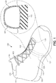
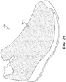
- FIG. 1 is an isometric view of an embodiment of an article of footwear 100.
- Article of footwear 100 may include upper 101 and sole 102.
- upper 101 may further include tongue 104.
- Upper 101 may include an opening or throat 105 that allows the wearer to insert his or her foot into the footwear.
- upper 101 may also include laces 103, which can be used to tighten or otherwise adjust the size of throat 105 around a foot.
- Article of footwear 100 can include provisions for adaptively tightening to a user's foot. For example, some embodiments may incorporate components that tighten in response to activities such as jumping, running or cutting, thereby minimizing slip between a user's foot and article of footwear 100 during such activities.
- article of footwear 100 may include one or more straps comprising reactive materials. As previously discussed, such materials may expand along dimensions perpendicular to the tensioning direction (e.g., expand in width and thickness while undergoing lengthwise tensioning).
- a strap refers to any generally two-dimensional member with a thickness much less than the length and/or width.
- a strap may have an elongated shape, including for example, a rectangular area.
- the term strap is not intended to be limited to a particular shape and could include any member having any shape.
- a strap could extend through a large portion of an upper.
- a strap may comprise a substantial entirety of the upper.
- article of footwear 100 may include reactive strap 120.
- reactive strap 120 may be disposed internally to upper 101. More specifically, in some embodiments, a first end 121 of reactive strap 120 may be attached to the bottom of the interior of the medial side 110 of footwear 100, an intermediate portion 122 of reactive strap 120 may be routed over the arch of the wearer's foot, below tongue 104, and a second end 123 of reactive strap 120 may be attached to the lateral side 111 of article of footwear 100. In other embodiments, the arrangement of reactive strap 120 along article of footwear 100 could vary in any manner. Other possible arrangements or configurations are described in further detail below.
- Reactive strap 120 can be attached at the bottom of the interior lateral and medial sides of upper 101 using stitching, stapling, fusion, adhesives or any other type of permanent attachment method. It can alternatively be attached to the top surface of the sole on both sides of the footwear, instead of to the interior sides of the footwear. Reactive strap 120 is shown in phantom in FIG. 1 , because reactive strap 120 is wholly within the footwear.
- the current embodiment describes a generally unitary reactive strap 120.
- reactive strap 120 may comprise a single layer.
- a strap including a reactive material could incorporate two or more layers or portions having distinct material properties.
- An example of a composite strap including a reactive layer and an additional layer with different material properties from the reactive layer is described in further detail below.
- reactive strap 120 may be made from various materials.
- reactive strap 120 may be made from any materials having a negative Poisson's ratio, including, for example, auxetic materials. Such materials are available, for example, from Advanced Fabric Technologies, Houston, Texas and from Auxetic Technologies Ltd., Bolton, UK.
- the call-out in FIG. 1 shows a cross-section of footwear 100.
- the call-out in FIG. 1 shows how unitary reactive strap 120 fits within the fabric of upper 101.
- strap 120 When strap 120 is under tension, its thickness and width increase, as discussed below with reference to FIGS. 2-4 . Because strap 120 is constrained by the fabric of upper 101 from expanding outwards, any increase in thickness of strap 120 would force strap 120 to press more firmly against the foot and thus serves to hold the footwear more securely on the foot.
- FIG. 1 shows a generic shoe
- other embodiments of the footwear could include, for example, running shoes, walking shoes, basketball shoes, tennis shoes, soccer shoes, baseball shoes, skates or boots, all of which need to secure the footwear to the foot so as to maximize comfort and performance.
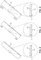
- FIGS. 2-4 show how reactive strap 120 behaves under longitudinal tension.
- strap 120 is not under tension, and it has a thickness T 0 and a width W 0.
- FIG. 3 strap 120 is under tension. Because it is under tension, its thickness has increased to T 1 (which is greater than T 0 ) and its width has increased to W 1 (which is greater than W 0 ).
- FIG. 4 strap 120 is under increased tension, and its thickness is now T 2 (which is greater than T 1 ) and its width is now W 2 (which is greater than W 1 ).
- reactive strap 120 may tend to expand in thickness and width as reactive strap 120 is pulled longitudinally. This is in contrast to various other straps that may generally contract in width and thickness under longitudinal tension (e.g., under stretching).
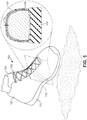
- FIGS. 5 and 6 show the embodiment of FIG. 1 in action.
- footwear 100 is not in contact with the playing surface.
- Reactive strap 120 only experiences minimal longitudinal tension. For that reason, the thickness and width of reactive strap 120 is not significantly greater than the thickness T 0 and width W 0 , respectively, of reactive strap 120 when it is not under any tension.
- FIG. 6 footwear 100 is in contact with the playing surface.
- Reactive strap 120 is under tension, for example because the wearer is pushing off his or her forefoot to leap or accelerate. Because it is under tension, the thickness and width of reactive strap 120 have increased.
- the thickness of reactive strap 120 has increased to T 3 (which is substantially greater than T 0 ).
- reactive strap 120 may provide an increased radially inward force on the foot, thereby preventing in-shoe slip and enhancing support for the wearer.
- FIGS. 1-6 illustrates an article of footwear including a reactive strap that is disposed internally to the upper.
- the entirety of the strap is disposed inwardly of the outer sidewalls of the upper as well as beneath the tongue.
- some portions of a reactive strap could extend outwardly of the upper and/or tongue.
- the entirety of a reactive strap could extend outwardly of the upper and/or tongue.
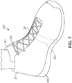
- FIG. 7 is an isometric view of an example of another embodiment of an article of footwear.
- article of footwear 200 may be similar to article of footwear 100 discussed above.
- article of footwear 200 may include upper 201, sole 202 as well as laces 203 and tongue 204.
- reactive strap 220 is routed within footwear 200 above tongue 204 and below laces 203.
- reactive strap 220 may be permanently attached to the interior of article of footwear 200 footwear at both the lateral side and the medial side, for example by stitching, stapling, fusing or adhesives. While the end portions of reactive strap 220 may be disposed internally within upper 201, an intermediate portion 221 of reactive strap 220 may be exposed along an exterior of article of footwear 100.
- Reactive strap 220 can be attached either to the medial and lateral interior sides of the upper, respectively, or to the medial and lateral sides of the sole, respectively.
- reactive strap 220 When reactive strap 220 is under tension, for example because the wearer is jumping, its thickness and width increase, thus tightening the footwear around the foot and providing improved stability. In this embodiment, reactive strap 220 functions to press tongue 204 down against the top of the wearer's foot, thus spreading the stress over a larger area. Such an embodiment could be selected in situations where it may be desirable to spread out the stresses applied by a strap.
- FIG. 8 is an isometric view of another example of the embodiment of an article of footwear.
- the reactive strap 220 is attached at one end to the bottom of the interior of the medial side of upper 201 of footwear 200 or to sole 202.
- Reactive strap 220 is routed up the side and then between laces 203 and tongue 204 of footwear 200, such that a portion 222 of reactive strap 220 passes over tongue 204.
- Reactive strap 220 could also be routed beneath the tongue.
- Reactive strap 220 then emerges from the interior of the lateral side of the footwear through slot 250.
- Reactive strap 220 is then attached to the exterior of the lateral side of the footwear using, for example, a hook-and-loop fastener 251 such as Velcro ® , as shown in FIG. 8 , or by some other detachable attachment method such as a buckle, snaps, buttons or laces.
- the effective length of reactive strap 220 may be adjusted.
- the point of attachment between reactive strap 220 and fastener 251 may function as the effective end of reactive strap 220 for purposes of tensioning the foot. Therefore, adjusting the position of reactive strap 220 relative to fastener 251 allows a user to pre-tension reactive strap 220 as desired.
- the embodiment of FIG. 8 allows for adjustment of the effective length of the reactive strap.
- a strap (including a reactive strap) may be routed either entirely within the upper, as in the embodiment shown in FIG. 1 , or may be routed over the tongue, as shown in FIGS. 7 and 8 .
- the strap may be wrapped over the instep or over the forefoot. It may also be wrapped around the heel or the ankle.
- the strap(s) may be attached to the sole.
- one or more straps may be used. For example, one strap may wrap around the heel, a second strap may wrap around the ankle, a third strap may wrap over the instep and a fourth strap may wrap over the forefoot.
- a strap is generally rectangular, it may have any shape that is suitable for the particular footwear, as long as it can be characterized as having a length, a width and a thickness.
- the strap may be roughly rectangular, oval, triangular or trapezoidal, or a combination of such shapes.
- the shape of the strap could be regular or irregular.
- Embodiments of the article of footwear may use a composite strap instead of a unitary strap.
- a composite strap may include two or more layers or portions of distinct material.
- a composite strap may include at least two layers, where at least one of the two layers is made of a reactive material.
- the composite strap could be routed within the upper, as in the examples shown in FIGS. 5-8 . As shown in FIG. 9 , the composite strap can also be routed over the upper instead of within the upper.
- FIG. 9 illustrates another article of footwear 300.
- Article of footwear 300 may include an upper 301 and sole 302. Further, article of footwear 300 may include laces 303 as well as tongue 304.
- article of footwear 300 may include composite strap 320.
- Composite strap 320 as shown in FIG. 9 , has at least two layers: a reactive layer 321 on the outward side of the composite strap and an inelastic layer 322 on its inward side.
- reactive layer 321 and inelastic layer 322 may have different material characteristics.
- reactive layer 321 may be fabricated from material with a negative Poisson's ratio so that as reactive layer 321 is placed in tension along a first direction, reactive layer 321 may expand in directions that are generally orthogonal to the first direction.
- reactive layer 321 may expand in thickness or width or in both thickness and width.
- inelastic layer 322 when tension is applied in a longitudinal direction to inelastic layer 322, inelastic layer 322 substantially resists expansion in the longitudinal direction as well as the lateral and vertical directions. As described in further detail below, this arrangement of reactive layer 321 and inelastic layer 322 allows the expansion of reactive layer 321 in dimensions orthogonal to its length to be controlled in a manner that facilitates increased support for a foot.
- Inelastic layer 322 can be made from materials including, but not limited to: canvas, nylon, Dacron ® , denim, EVA or other materials that do not stretch substantially when under tension.
- Reactive layer 321 may be made from any materials having a negative Poisson's ratio, including, for example, auxetic materials. Such materials are available, for example, from Advanced Fabric Technologies, Houston, Texas and from Auxetic Technologies Ltd., Bolton, UK. However, it will be understood that a reactive layer may generally be made of any materials that exhibit the material properties described above, including expansion in a direction orthogonal to the direction of applied tension.
- reactive layer 321 may be attached to inelastic layer 322 only at its two longitudinal ends, for example by stitching or stapling, or by using adhesives. In other embodiments, reactive layer 321 and inelastic layer 322 could be joined at any other regions. In still other embodiments, reactive layer 321 may be disposed adjacent to inelastic layer 322, but not directly joined to inelastic layer 322.
- Composite strap 320 may be routed within article of footwear 300, or over the footwear, as described below. Depending on the particular footwear and the specific application, the two ends of composite strap 320 may be attached to the medial and lateral sides of upper 301, for example. In other embodiments, for example, they could also be attached to sole 302 or at the interface of upper 301 to sole 302.
- the attachment method may be fixed, such as stitching, stapling, fusing or using adhesives, or detachable, such as by using buckles, buttons, hook and loop fasteners such as Velcro ® , snaps or laces.
- inelastic layer 322 is attached to footwear 300 on its medial side by stitching (not shown in FIG. 9 ). It is attached at the lateral side of footwear 300 by stitching 330. As shown in the call-out in FIG. 9 and discussed in more detail below with reference to FIGS. 10-12 , when reactive layer 321 is not under tension, it has a thickness T 0 and a width W 0 .
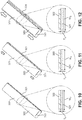
- FIGS. 10-12 are isometric views of a composite strap showing how its geometry changes under tension.
- FIG. 10 is an isometric view of composite strap 320 when it is not under tension.
- Reactive layer 321 is annotated to designate the width of the reactive layer as W 0 and the thickness of the reactive layer as T 0 .
- Reactive layer 321 is attached to inelastic layer 322 at both ends by stitching 323.
- reactive layer 321 is not attached in any other way to inelastic layer 322.
- reactive layer 321 and inelastic layer 322 could be attached at other locations.
- reactive layer 321 and inelastic layer may not be attached to each other at any location.
- FIG. 11 is an isometric view of an example of composite strap 320 when it is under longitudinal tension, as indicated by the arrows at both ends of the strap.
- the thickness T 4 and width W 4 of reactive layer 321 have increased compared to the thickness T 0 and width W 0 when the reactive layer is not under tension (as shown in FIG. 10 ).
- T 4 is greater than T 0 and W 4 is greater than W 0 .
- FIG. 12 is an isometric view of an example of composite strap 320 when it is under increased longitudinal tension compared to the example shown in FIG. 11 .
- the thickness T 5 and width W 5 of reactive layer 321 have increased compared to the thickness T 1 and width W 1 when the reactive layer is under less tension (as shown in FIG. 11 ).
- T 5 is greater than T 4 and W 5 is greater than W 4 .
- the inelastic layer does not experience any significant changes in any of its dimensions.
- the length may increase a minimal amount, and the inelastic layer may have even smaller and less significant changes in its width and its thickness.
- a composite strap could include a layer different from a reactive layer that does change significantly in one or more dimensions.
- some embodiments could include an elastic layer that increases in length and contracts in width and/or thickness under longitudinal tension.
- FIG. 13 is an isometric view of an article of footwear in action.
- composite strap 320 is not experiencing substantial longitudinal tension.
- reactive layer 321 has a thickness and width that is not substantially greater than the thickness T 0 and width W 0 when reactive layer 321 is not under tension.
- composite strap 320 is attached to the lateral side of article of footwear 300 by buckle 331.
- Composite strap 320 could also be attached using any other detachable device such as a hook and loop fastener (such as Velcro ® ), laces, snaps or other detachable mechanical device, or by a permanent attachment such as stitches, staples, fusion or adhesives.
- Composite strap 320 can be attached to the medial side of article of footwear 300 by, for example, using a permanent attachment method such as stitching, stapling, fusion or adhesives.
- FIG. 14 is an isometric view of the article of footwear shown in FIG. 13 , when the footwear is pressed hard against the playing surface, for example because the wearer is leaping or accelerating forward.
- composite strap 320 is under greater tension than in the example shown in FIG. 13 .
- reactive layer 321 is under tension, its thickness and width increase to T 6 and W 6 , respectively.
- 321 reactive layer is constrained by inelastic layer 322, it presses more firmly down (or radially inwardly) towards the top of the footwear.
- the increased width of reactive layer 321 results in a wider contact area between composite strap 320 and the top of article of footwear 300. Both of these actions - the increased thickness and the increased width - serve to hold article of footwear 300 more securely to the wearer's foot and thus provide more stability to the wearer.
- the composite strap may be attached to any part of the footwear using any kind of attachment mechanism, including both permanent attachment mechanisms such as stitching, stapling, using adhesives or fusing, or a detachable mechanism such as a buckle, a hook and loop fastener, a snap or laces.
- a permanent attachment method could be used on the medial side and either a permanent or detachable method could be used on the lateral side.
- other embodiments could include fasteners on the lateral side.
- the footwear shown generically in FIGS. 9 and 13-14 is representative of many kinds of footwear, including for example, running shoes, walking shoes, hiking boots, work boots, tennis shoes, jogging shoes, basketball shoes, soccer shoes, baseball shoes, skates, ski boots and other types of footwear.
- Straps (including unitary and composite straps) with reactive materials could be disposed on any portion of an article of footwear.
- a strap can be positioned at the instep, as shown in FIGs. 1 , 5-9 and 13-14 .
- a strap could wrap around the ankle and/or the heel.
- a strap could be positioned at the forefoot of the footwear.
- straps could have any kinds of shapes. Although the strap is shown in the figures as having a generally rectangular shape, in other embodiments a strap could have an oval shape or any other shape that allows the material to be held under tension in one direction. Examples of other possible shapes for a strap include, but are not limited to: round, triangular rectangular, polygonal, regular and irregular shapes.
- reactive material may be integrated within an upper.
- a reactive material can comprise one or more portions or sections of the upper. These portions of a reactive material may be disposed adjacent portions of more conventional upper materials.
- FIGS. 15 through 21 illustrate still further configurations for integrating a reactive material into an upper.
- a reactive material may comprise a section of an upper material.
- article of footwear 430 may include upper 432.
- Upper 432 may include a forward portion 434, a rearward portion 436 and an intermediate portion 438 that is disposed between the forward portion 434 and the rearward portion 436.
- Intermediate portion 438 may be further separated into a lateral intermediate portion 440 and a medial intermediate portion 442, which may be separated by throat opening 446.
- forward portion 434 and rearward portion 436 may comprise conventional upper materials such as synthetic leather, mesh materials as well as possibly other materials.
- forward portion 434 and rearward portion 436 may comprise materials with a positive Poisson's ratio.
- intermediate portion 438 (including both lateral intermediate portion 440 and medial intermediate portion 442) may be made of a reactive material with a negative Poisson's ratio.
- intermediate portion 438 may comprise a portion that that expands in thickness under longitudinal tension.
- the relatively narrow width of intermediate portion 438 compared with forward portion 434 and rearward portion 436, may allow intermediate portion 438 to operate in a similar manner to a strap, thereby constraining the radial portion of a foot within upper 432 in a similar manner to straps of the previous embodiments.
- FIGS. 15 and 16 illustrate an embodiment of intermediate portion 438 comprising a reactive material that is generally flush with an outer surface 448 of upper 432 defined by forward portion 434 and rearward portion 438.
- intermediate portion 438 could be recessed below, or extended above, outer surface 448 of upper 432.
- FIG. 17 illustrates a cross sectional view of a portion of upper 432 in which an intermediate portion 437 is recessed below outer surface 448.
- FIG. 18 illustrates a cross sectional view of a portion of upper 432 in which an intermediate portion 439 is raised above outer surface 448.
- the current embodiment discusses the relative position of an intermediate portion with respect to an outer surface of an upper, in other embodiments an intermediate portion could be flush, recessed or lowered similar with respect to an inner surface of an upper.
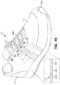
- FIG. 19 illustrates a schematic view of an embodiment of an article of footwear 450 including an upper 452 with integral tongue 454.
- upper 452 may further include reactive strap 456 that is integral with upper 452.
- Reactive strap 456 may extend continuously from a lateral side to a medial side of upper 452.
- upper 452 may operate without a traditional lacing system, thereby providing a loose fit until tension is applied, at which point reactive strap 456 may tighten around a foot.
- a reactive material could be integrated into various regions of an article.
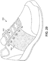
- article 460 may include a reactive portion 462 that extends along a large portion on either side of throat opening 446.
- reactive portion 462 is seen to have a substantially greater width than intermediate portion 438 shown in FIGS. 15 and 16 .
- a reactive material 471 may comprise the majority of an upper 470, as shown in FIG. 21 .
- the substantial entirety of upper 470 may increase in thickness when tensioned along any direction approximately parallel to the surface of upper 470.
- embodiments can include uppers having various different portions comprising a reactive material.
- the size, shape and location of these portions can vary according to factors including, but not limited to: type of footwear, desired support during inactivity, desired support during various kinds of activity, desired locations for support as well as other factors.
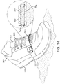
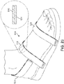
- FIG. 22 is an isometric view of an article of footwear, in this case a hitop shoe, with a composite strap routed around the ankle.
- Composite strap 420 has an inner reactive layer 421 and an outer inelastic layer 422, i.e., composite strap 420 is similar to the composite strap shown in FIGS. 10-12 .
- Composite strap 420 is held in place on one side of the footwear by lace 403. It is then routed over upper 401 around the wearer's ankle to the other side of the footwear, where it is held by lace 403. When the wearer flexes or turns his or her ankle, thus creating additional tension on composite strap 420, the inner reactive layer expands in thickness and/or in width, thus providing additional support for the wearer's ankle.
- FIGS. 23 , 24 and 25 show examples of the use of a composite strap, on a scandal, a slipper and a flipper, respectively.
- the composite strap has an inner reactive layer and an outer inelastic layer.
- the outer inelastic layer serves to constrain the inner reactive layer when that layer is under tension, such that the reactive layer is forced to exert additional pressure on the wearer's foot and thus more securely hold the footwear onto the foot.
- FIG. 23 is an isometric view of a sandal with composite straps wrapped around the heel, at the instep and at the forefoot.
- sandals could have any one or two of these composite straps, or all three composite straps.
- Still other embodiments could include four or more composite straps.
- some embodiments could incorporate a combination of unitary straps and composite straps.
- Composite strap 521, composite strap 522 and composite strap 523 are generally similar to the composite strap shown in FIGS. 10-12 .
- Each composite strap may include an outer inelastic layer 530 and an inner reactive layer 531, as indicated specifically for composite strap 521 in FIG. 23 .
- composite strap 521 is attached on either side of the foot to composite strap 522. However in other examples it could be attached on either side of the sole.
- Composite strap 522 and composite strap 523 can be attached to the sole using a permanent attachment method such as stitching, stapling, fusion or adhesives, or by a detachable method such as buckles, hook and loop fasteners, hooks, buttons or laces.
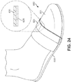
- FIG. 24 is an isometric view of a slipper 600 with a composite strap at the forefoot.
- Composite strap 621 is generally similar to the composite strap shown in FIGS. 10-12 (including an outer inelastic layer 630 and an inner reactive layer 631).
- Composite strap 621 may be attached to one side of sole 602 using a permanent attachment method such as stitching, stapling, fusion or adhesives, or by a detachable method such as buckles, hook and loop fasteners, hooks, buttons or laces.
- composite strap 621 may be attached at the other side of sole 602 by a permanent attachment method. It could alternatively be attached to the sides of upper 601.
- the wearer's foot would fit comfortably in slipper 600 when strap 621 is not under tension, but would tighten up when the wearer is walking so as to prevent the slipper from slipping off the foot.
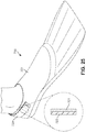
- FIG. 25 is an isometric view of a flipper 700, with a composite strap around the heel.
- Composite strap 720 is generally similar to the composite strap shown in FIGS. 10-12 ., i.e ., it has an inner reactive layer 721 and an outer inelastic layer 722. It can be attached to one side of the heel using a permanent attachment method such as stitching, stapling, fusion or adhesives, or by a detachable method such as buckles, hook and loop fasteners, hooks, buttons or laces. In some embodiments, composite strap 720 may be attached at the other side of the heel by a permanent attachment method.
- flipper 700 would normally be held fairly tightly on the wearer's foot by strap 721 when strap 721 is not under tension. However, when the wearer is kicking his or her feet when swimming, the increased tension on strap 721 provides increased tightening to secure flipper 700 even more firmly to the foot.
- unitary reactive straps or composite straps including a reactive layer may be used in many other types of footwear, such as boots, skates, ski boots, ballet shoes, football shoes, bicycle shoes, soccer shoes and volleyball shoes.
- These articles of footwear may include one or several unitary or composite straps, at any one or more different locations, such as at the instep, the heel, the ankle and the forefoot.
Description
- The present embodiments relate generally to an article of footwear, and in particular to restraining elements in articles of footwear intended for use during athletic activities such as running, walking, skating, skiing, bicycling or jumping, and/or during games or sports such as basketball, soccer, volleyball, baseball, football, tennis, field hockey, ice hockey and other games or sports.
- Articles of footwear typically have at least two major components, an upper that provides the enclosure for receiving the wearer's foot, and a sole secured to the upper that is the primary contact to the ground or playing surface. The footwear may also use some type of fastening system, for example, laces or straps or a combination of both, to secure the footwear around the wearer's foot. When the footwear is unfastened, the fastening system allows the person wearing the footwear to easily insert his/her foot into the footwear. When the fastening system is fastened, it securely holds the footwear to the foot, and provides stability and support appropriate for the intended activity or sport, while allowing sufficient flexibility.
-
US 5,819,439 discloses an article of footwear comprising an upper, a sole and a strap attached on the upper. - The invention relates to an article of footwear as claimed in
claim 1. Preferred embodiments are specified in the dependent claims. - As used herein, the term "reactive material" shall mean a material that, when it is placed under tension in a first direction, it increases its dimensions in one or both of the directions orthogonal to the first direction. For example, if the material is in the form of a strap having a length, a width and a thickness, then when the strap is under tension longitudinally (i.e., lengthwise), it increases in width and/or in thickness. Reactive materials may be characterized as having a negative Poisson's ratio. In contrast, conventional materials tend to contract in width and thickness as their length expands. Examples of materials having these reactive properties are auxetic materials.
- In one aspect, the article of footwear includes an upper, a sole, and a strap attached at one end to the medial side of the footwear, either at the side of the upper or at the sole, and attached at the other end to the lateral side of the footwear, either at the side of the upper or at the sole. The strap includes a layer made of reactive material. This layer will be referred herein as a "reactive layer." The reactive layer is constrained from expanding outwards. When the person wearing the footwear engages in an activity, such as leaping or accelerating, that puts the strap under increased longitudinal tension, the reactive layer increases its thickness and/or width and thus more firmly holds the footwear onto the foot.
- In another aspect, the article of footwear includes an upper, a sole and a strap made of reactive material. The strap is attached at its medial and lateral ends to the medial and lateral sides, respectively, of the upper, or is attached to the medial and lateral sides, respectively, of the sole. The strap is routed, either partially or entirely within the footwear, such that when the strap is under longitudinal tension, the fabric of the upper constrains the strap so that when it expands in thickness it presses more firmly against the wearer's foot.
- Other systems, methods, features and advantages of the embodiments will be, or will become, apparent to one of ordinary skill in the art upon examination of the following figures and detailed description. It is intended that all such additional systems, methods, features and advantages be included within this description and this summary, be within the scope of the embodiments, and be protected by the following claims.
- The embodiments can be better understood with reference to the following drawings and description. The components in the figures are not necessarily to scale, emphasis instead being placed upon illustrating the principles of the embodiments. Moreover, in the figures, like reference numerals designate corresponding parts throughout the different views.
-
FIG. 1 is an isometric view of an embodiment of an article of footwear with an example of a unitary reactive strap; -
FIG. 2 is an isometric view of an embodiment of a unitary strap when it is not subject to any longitudinal tension; -
FIG. 3 is an isometric view of an embodiment of a unitary strap under longitudinal tension; -
FIG. 4 is an isometric view of an embodiment of a unitary strap under increased longitudinal tension; -
FIG. 5 is an isometric view of the embodiment of an article of footwear ofFIG. 1 above a playing surface using an example of a unitary strap; -
FIG. 6 is an isometric view of the embodiment of an article of footwear ofFIG. 1 in contact with a playing surface using an example of a unitary strap. -
FIG. 7 is an isometric view of another embodiment of an article of footwear using an example of a unitary strap; -
FIG. 8 is an isometric view of yet another embodiment of an article of footwear using a unitary strap; -
FIG. 9 is an isometric view of an embodiment of an article of footwear using a composite strap; -
FIG. 10 is an isometric view of an embodiment of a composite strap when it is not subject to any longitudinal tension; -
FIG. 11 is an isometric view of an embodiment of a composite strap under longitudinal tension; -
FIG. 12 is an isometric view of an embodiment of a composite strap under increased longitudinal tension; -
FIG. 13 is an isometric view of the footwear ofFIG. 9 above a playing surface; -
FIG. 14 is an isometric view of the footwear ofFIG. 9 in contact with a playing surface; -
FIG. 15 is an isometric lateral view of an embodiment of an article of footwear including an integrated reactive strap; -
FIG. 16 is an isometric medial view of an embodiment of an article of footwear including an integrated reactive strap; -
FIG. 17 is an enlarged cross-sectional view of a portion of an upper including a reactive strap; -
FIG. 18 is an enlarged cross-sectional view of a portion of an upper including a reactive strap; -
FIG. 19 is an isometric view of an embodiment of an article with an integral tongue including a reactive strap; -
FIG. 20 is an isometric view of an embodiment of an article of footwear with a reactive material integrated into a throat portion of an upper; -
FIG. 21 is an isometric view of an embodiment of an article of footwear including an upper comprising a reactive material; -
FIG. 22 is an isometric view of an embodiment of an article of footwear with a composite strap for providing increased support at a wearer's ankle; -
FIG. 23 is an isometric view of an embodiment of a sandal with composite straps; -
FIG. 24 is an isometric view of an embodiment of a slipper with a composite strap; and -
FIG. 25 is an isometric view of an embodiment of a flipper with a composite strap. - For clarity, the detailed descriptions herein describe certain exemplary embodiments, but the disclosure herein may be applied to any article of footwear comprising certain of the features described herein and recited in the claims. In particular, although the following detailed description discusses exemplary embodiments, in the form of footwear such as running shoes, basketball shoes, sandals and flippers, the disclosures herein may be applied to a wide range of footwear.
- For consistency and convenience, directional adjectives are employed throughout this detailed description corresponding to the illustrated embodiments. The term "longitudinal" as used throughout this detailed description and in the claims refers to a direction extending a length (or longest dimension) of a component, such as a strap. Also, the term "lateral" as used throughout this detailed description and in the claims refers to a direction extending along a width of a component, such as a strap. The lateral direction may generally be perpendicular to the longitudinal direction. Furthermore, the term "vertical" as used throughout this detailed description and in the claims refers to a direction generally perpendicular to a lateral and longitudinal direction. The vertical direction may be associated with the thickness or depth of a component, such as a strap.
-
FIG. 1 is an isometric view of an embodiment of an article offootwear 100. Article offootwear 100 may include upper 101 and sole 102. In some embodiments, upper 101 may further includetongue 104.Upper 101 may include an opening orthroat 105 that allows the wearer to insert his or her foot into the footwear. In some embodiments, upper 101 may also includelaces 103, which can be used to tighten or otherwise adjust the size ofthroat 105 around a foot. - Article of
footwear 100 can include provisions for adaptively tightening to a user's foot. For example, some embodiments may incorporate components that tighten in response to activities such as jumping, running or cutting, thereby minimizing slip between a user's foot and article offootwear 100 during such activities. In some embodiments, article offootwear 100 may include one or more straps comprising reactive materials. As previously discussed, such materials may expand along dimensions perpendicular to the tensioning direction (e.g., expand in width and thickness while undergoing lengthwise tensioning). - As used throughout this detailed description and in the claims, the term "strap" refers to any generally two-dimensional member with a thickness much less than the length and/or width. In some cases, a strap may have an elongated shape, including for example, a rectangular area. However, the term strap is not intended to be limited to a particular shape and could include any member having any shape. For example, in some embodiments, a strap could extend through a large portion of an upper. In some embodiments, a strap may comprise a substantial entirety of the upper.
- In some embodiments, article of
footwear 100 may includereactive strap 120. In some embodiments,reactive strap 120 may be disposed internally to upper 101. More specifically, in some embodiments, afirst end 121 ofreactive strap 120 may be attached to the bottom of the interior of themedial side 110 offootwear 100, anintermediate portion 122 ofreactive strap 120 may be routed over the arch of the wearer's foot, belowtongue 104, and asecond end 123 ofreactive strap 120 may be attached to the lateral side 111 of article offootwear 100. In other embodiments, the arrangement ofreactive strap 120 along article offootwear 100 could vary in any manner. Other possible arrangements or configurations are described in further detail below. -
Reactive strap 120 can be attached at the bottom of the interior lateral and medial sides of upper 101 using stitching, stapling, fusion, adhesives or any other type of permanent attachment method. It can alternatively be attached to the top surface of the sole on both sides of the footwear, instead of to the interior sides of the footwear.Reactive strap 120 is shown in phantom inFIG. 1 , becausereactive strap 120 is wholly within the footwear. - The current embodiment describes a generally unitary
reactive strap 120. In other words,reactive strap 120 may comprise a single layer. However, in other embodiments, a strap including a reactive material could incorporate two or more layers or portions having distinct material properties. An example of a composite strap including a reactive layer and an additional layer with different material properties from the reactive layer is described in further detail below. - In different embodiments,
reactive strap 120 may be made from various materials. In some embodiments,reactive strap 120 may be made from any materials having a negative Poisson's ratio, including, for example, auxetic materials. Such materials are available, for example, from Advanced Fabric Technologies, Houston, Texas and from Auxetic Technologies Ltd., Bolton, UK. - The call-out in
FIG. 1 shows a cross-section offootwear 100. In particular, the call-out inFIG. 1 shows how unitaryreactive strap 120 fits within the fabric of upper 101. Whenstrap 120 is under tension, its thickness and width increase, as discussed below with reference toFIGS. 2-4 . Becausestrap 120 is constrained by the fabric of upper 101 from expanding outwards, any increase in thickness ofstrap 120 would forcestrap 120 to press more firmly against the foot and thus serves to hold the footwear more securely on the foot. - Although
FIG. 1 shows a generic shoe, other embodiments of the footwear could include, for example, running shoes, walking shoes, basketball shoes, tennis shoes, soccer shoes, baseball shoes, skates or boots, all of which need to secure the footwear to the foot so as to maximize comfort and performance. -
FIGS. 2-4 show howreactive strap 120 behaves under longitudinal tension. InFIG. 2 ,strap 120 is not under tension, and it has a thickness T0 and a width W0. InFIG. 3 ,strap 120 is under tension. Because it is under tension, its thickness has increased to T1 (which is greater than T0) and its width has increased to W1 (which is greater than W0). InFIG. 4 ,strap 120 is under increased tension, and its thickness is now T2 (which is greater than T1) and its width is now W2 (which is greater than W1). Thus, as seen inFIGS. 2-4 ,reactive strap 120 may tend to expand in thickness and width asreactive strap 120 is pulled longitudinally. This is in contrast to various other straps that may generally contract in width and thickness under longitudinal tension (e.g., under stretching). - In some cases, there may be a linear relationship between the increase in thickness and/or width of
strap 120 and an increase in length ofstrap 120 under longitudinal tension. In the general case, however, there need not be such a relationship. In other embodiments, for example, there could be a nonlinear relationship between the increase in thickness and/or width ofstrap 120 and the increase in length ofstrap 120 under longitudinal tension. -
FIGS. 5 and6 show the embodiment ofFIG. 1 in action. InFIG. 5 ,footwear 100 is not in contact with the playing surface.Reactive strap 120 only experiences minimal longitudinal tension. For that reason, the thickness and width ofreactive strap 120 is not significantly greater than the thickness T0 and width W0, respectively, ofreactive strap 120 when it is not under any tension. InFIG. 6 ,footwear 100 is in contact with the playing surface.Reactive strap 120 is under tension, for example because the wearer is pushing off his or her forefoot to leap or accelerate. Because it is under tension, the thickness and width ofreactive strap 120 have increased. For example, the thickness ofreactive strap 120 has increased to T3 (which is substantially greater than T0). Moreover, as the thickness ofreactive strap 120 increases,reactive strap 120 may provide an increased radially inward force on the foot, thereby preventing in-shoe slip and enhancing support for the wearer. - The embodiment shown in
FIGS. 1-6 illustrates an article of footwear including a reactive strap that is disposed internally to the upper. In particular, the entirety of the strap is disposed inwardly of the outer sidewalls of the upper as well as beneath the tongue. In other embodiments, however, some portions of a reactive strap could extend outwardly of the upper and/or tongue. In still other embodiments, the entirety of a reactive strap could extend outwardly of the upper and/or tongue. -
FIG. 7 is an isometric view of an example of another embodiment of an article of footwear. In this embodiment, article offootwear 200 may be similar to article offootwear 100 discussed above. In particular, article offootwear 200 may include upper 201, sole 202 as well aslaces 203 andtongue 204. In this embodiment,reactive strap 220 is routed withinfootwear 200 abovetongue 204 and below laces 203. In particular,reactive strap 220 may be permanently attached to the interior of article offootwear 200 footwear at both the lateral side and the medial side, for example by stitching, stapling, fusing or adhesives. While the end portions ofreactive strap 220 may be disposed internally within upper 201, anintermediate portion 221 ofreactive strap 220 may be exposed along an exterior of article offootwear 100.Reactive strap 220 can be attached either to the medial and lateral interior sides of the upper, respectively, or to the medial and lateral sides of the sole, respectively. - When
reactive strap 220 is under tension, for example because the wearer is jumping, its thickness and width increase, thus tightening the footwear around the foot and providing improved stability. In this embodiment,reactive strap 220 functions to presstongue 204 down against the top of the wearer's foot, thus spreading the stress over a larger area. Such an embodiment could be selected in situations where it may be desirable to spread out the stresses applied by a strap. -
FIG. 8 is an isometric view of another example of the embodiment of an article of footwear. In this example, thereactive strap 220 is attached at one end to the bottom of the interior of the medial side of upper 201 offootwear 200 or to sole 202.Reactive strap 220 is routed up the side and then betweenlaces 203 andtongue 204 offootwear 200, such that aportion 222 ofreactive strap 220 passes overtongue 204.Reactive strap 220 could also be routed beneath the tongue.Reactive strap 220 then emerges from the interior of the lateral side of the footwear throughslot 250.Reactive strap 220 is then attached to the exterior of the lateral side of the footwear using, for example, a hook-and-loop fastener 251 such as Velcro®, as shown inFIG. 8 , or by some other detachable attachment method such as a buckle, snaps, buttons or laces. - Using the configuration shown in
FIG. 8 , the effective length ofreactive strap 220 may be adjusted. Specifically, the point of attachment betweenreactive strap 220 andfastener 251 may function as the effective end ofreactive strap 220 for purposes of tensioning the foot. Therefore, adjusting the position ofreactive strap 220 relative tofastener 251 allows a user to pre-tensionreactive strap 220 as desired. The embodiment ofFIG. 8 allows for adjustment of the effective length of the reactive strap. - Depending on the particular footwear, a strap (including a reactive strap) may be routed either entirely within the upper, as in the embodiment shown in
FIG. 1 , or may be routed over the tongue, as shown inFIGS. 7 and8 . The strap may be wrapped over the instep or over the forefoot. It may also be wrapped around the heel or the ankle. In the case of an article of footwear such as a sandal, that does not have an upper, the strap(s) may be attached to the sole. In general, whether attached to the upper or to the sole, one or more straps may be used. For example, one strap may wrap around the heel, a second strap may wrap around the ankle, a third strap may wrap over the instep and a fourth strap may wrap over the forefoot. - Although in many embodiments a strap is generally rectangular, it may have any shape that is suitable for the particular footwear, as long as it can be characterized as having a length, a width and a thickness. For example, the strap may be roughly rectangular, oval, triangular or trapezoidal, or a combination of such shapes. Moreover, the shape of the strap could be regular or irregular.
- Embodiments of the article of footwear may use a composite strap instead of a unitary strap. A composite strap may include two or more layers or portions of distinct material. In some cases, a composite strap may include at least two layers, where at least one of the two layers is made of a reactive material. The composite strap could be routed within the upper, as in the examples shown in
FIGS. 5-8 . As shown inFIG. 9 , the composite strap can also be routed over the upper instead of within the upper. -
FIG. 9 illustrates another article offootwear 300. Article offootwear 300 may include an upper 301 and sole 302. Further, article offootwear 300 may includelaces 303 as well astongue 304. - Some embodiments of article of
footwear 300 may includecomposite strap 320.Composite strap 320, as shown inFIG. 9 , has at least two layers: areactive layer 321 on the outward side of the composite strap and aninelastic layer 322 on its inward side. Generally,reactive layer 321 andinelastic layer 322 may have different material characteristics. In some embodiments,reactive layer 321 may be fabricated from material with a negative Poisson's ratio so that asreactive layer 321 is placed in tension along a first direction,reactive layer 321 may expand in directions that are generally orthogonal to the first direction. Thus, for example, asreactive layer 321 is placed under tension in a longitudinal direction alongcomposite strap 320,reactive layer 321 may expand in thickness or width or in both thickness and width. Moreover, when tension is applied in a longitudinal direction toinelastic layer 322,inelastic layer 322 substantially resists expansion in the longitudinal direction as well as the lateral and vertical directions. As described in further detail below, this arrangement ofreactive layer 321 andinelastic layer 322 allows the expansion ofreactive layer 321 in dimensions orthogonal to its length to be controlled in a manner that facilitates increased support for a foot. - Any materials or combination of materials can be used to achieve the above discussed material properties for
reactive layer 321 and/orinelastic layer 322.Inelastic layer 322 can be made from materials including, but not limited to: canvas, nylon, Dacron®, denim, EVA or other materials that do not stretch substantially when under tension.Reactive layer 321 may be made from any materials having a negative Poisson's ratio, including, for example, auxetic materials. Such materials are available, for example, from Advanced Fabric Technologies, Houston, Texas and from Auxetic Technologies Ltd., Bolton, UK. However, it will be understood that a reactive layer may generally be made of any materials that exhibit the material properties described above, including expansion in a direction orthogonal to the direction of applied tension. - In some embodiments,
reactive layer 321 may be attached toinelastic layer 322 only at its two longitudinal ends, for example by stitching or stapling, or by using adhesives. In other embodiments,reactive layer 321 andinelastic layer 322 could be joined at any other regions. In still other embodiments,reactive layer 321 may be disposed adjacent toinelastic layer 322, but not directly joined toinelastic layer 322. -
Composite strap 320 may be routed within article offootwear 300, or over the footwear, as described below. Depending on the particular footwear and the specific application, the two ends ofcomposite strap 320 may be attached to the medial and lateral sides of upper 301, for example. In other embodiments, for example, they could also be attached to sole 302 or at the interface of upper 301 to sole 302. The attachment method may be fixed, such as stitching, stapling, fusing or using adhesives, or detachable, such as by using buckles, buttons, hook and loop fasteners such as Velcro®, snaps or laces. - In the exemplary embodiment shown in
FIG. 9 ,inelastic layer 322 is attached tofootwear 300 on its medial side by stitching (not shown inFIG. 9 ). It is attached at the lateral side offootwear 300 by stitching 330. As shown in the call-out inFIG. 9 and discussed in more detail below with reference toFIGS. 10-12 , whenreactive layer 321 is not under tension, it has a thickness T0 and a width W0. -
FIGS. 10-12 are isometric views of a composite strap showing how its geometry changes under tension.FIG. 10 is an isometric view ofcomposite strap 320 when it is not under tension.Reactive layer 321 is annotated to designate the width of the reactive layer as W0 and the thickness of the reactive layer as T0.Reactive layer 321 is attached toinelastic layer 322 at both ends by stitching 323. In the current embodiment,reactive layer 321 is not attached in any other way toinelastic layer 322. However, it is possible that in other embodiments,reactive layer 321 andinelastic layer 322 could be attached at other locations. In still other embodiments,reactive layer 321 and inelastic layer may not be attached to each other at any location. -
FIG. 11 is an isometric view of an example ofcomposite strap 320 when it is under longitudinal tension, as indicated by the arrows at both ends of the strap. As shown inFIG. 11 , the thickness T4 and width W4 ofreactive layer 321 have increased compared to the thickness T0 and width W0 when the reactive layer is not under tension (as shown inFIG. 10 ). In other words, T4 is greater than T0 and W4 is greater than W0. -
FIG. 12 is an isometric view of an example ofcomposite strap 320 when it is under increased longitudinal tension compared to the example shown inFIG. 11 . In this case, the thickness T5 and width W5 ofreactive layer 321 have increased compared to the thickness T1 and width W1 when the reactive layer is under less tension (as shown inFIG. 11 ). In other words, T5 is greater than T4 and W5 is greater than W4. - To be clear, in the composite strap embodiments shown in
FIGS. 10-12 , the inelastic layer does not experience any significant changes in any of its dimensions. The length may increase a minimal amount, and the inelastic layer may have even smaller and less significant changes in its width and its thickness. In other embodiments, however, a composite strap could include a layer different from a reactive layer that does change significantly in one or more dimensions. For example, some embodiments could include an elastic layer that increases in length and contracts in width and/or thickness under longitudinal tension. -
FIG. 13 is an isometric view of an article of footwear in action. In this example, because the foot has not yet reached the ground,composite strap 320 is not experiencing substantial longitudinal tension. Becausecomposite strap 320 is not experiencing substantial longitudinal tension,reactive layer 321 has a thickness and width that is not substantially greater than the thickness T0 and width W0 whenreactive layer 321 is not under tension. - In the example shown in
FIG. 13 ,composite strap 320 is attached to the lateral side of article offootwear 300 bybuckle 331.Composite strap 320 could also be attached using any other detachable device such as a hook and loop fastener (such as Velcro®), laces, snaps or other detachable mechanical device, or by a permanent attachment such as stitches, staples, fusion or adhesives.Composite strap 320 can be attached to the medial side of article offootwear 300 by, for example, using a permanent attachment method such as stitching, stapling, fusion or adhesives. -
FIG. 14 is an isometric view of the article of footwear shown inFIG. 13 , when the footwear is pressed hard against the playing surface, for example because the wearer is leaping or accelerating forward. In this case,composite strap 320 is under greater tension than in the example shown inFIG. 13 . Becausereactive layer 321 is under tension, its thickness and width increase to T6 and W6, respectively. Because 321 reactive layer is constrained byinelastic layer 322, it presses more firmly down (or radially inwardly) towards the top of the footwear. At the same time, the increased width ofreactive layer 321 results in a wider contact area betweencomposite strap 320 and the top of article offootwear 300. Both of these actions - the increased thickness and the increased width - serve to hold article offootwear 300 more securely to the wearer's foot and thus provide more stability to the wearer. - The composite strap may be attached to any part of the footwear using any kind of attachment mechanism, including both permanent attachment mechanisms such as stitching, stapling, using adhesives or fusing, or a detachable mechanism such as a buckle, a hook and loop fastener, a snap or laces. In some embodiments, a permanent attachment method could be used on the medial side and either a permanent or detachable method could be used on the lateral side. However, other embodiments could include fasteners on the lateral side.
- The footwear shown generically in
FIGS. 9 and13-14 is representative of many kinds of footwear, including for example, running shoes, walking shoes, hiking boots, work boots, tennis shoes, jogging shoes, basketball shoes, soccer shoes, baseball shoes, skates, ski boots and other types of footwear. - Straps (including unitary and composite straps) with reactive materials could be disposed on any portion of an article of footwear. In some embodiments, a strap can be positioned at the instep, as shown in
FIGs. 1 ,5-9 and13-14 . In other embodiments, a strap could wrap around the ankle and/or the heel. In still other embodiments, a strap could be positioned at the forefoot of the footwear. - In different embodiments, straps could have any kinds of shapes. Although the strap is shown in the figures as having a generally rectangular shape, in other embodiments a strap could have an oval shape or any other shape that allows the material to be held under tension in one direction. Examples of other possible shapes for a strap include, but are not limited to: round, triangular rectangular, polygonal, regular and irregular shapes.
- In some embodiments, reactive material may be integrated within an upper. In particular, in some embodiments, a reactive material can comprise one or more portions or sections of the upper. These portions of a reactive material may be disposed adjacent portions of more conventional upper materials.
-
FIGS. 15 through 21 illustrate still further configurations for integrating a reactive material into an upper. Referring first toFIGS. 15 and16 , in some embodiments a reactive material may comprise a section of an upper material. As an example, article offootwear 430 may include upper 432.Upper 432 may include aforward portion 434, arearward portion 436 and anintermediate portion 438 that is disposed between theforward portion 434 and therearward portion 436.Intermediate portion 438 may be further separated into a lateralintermediate portion 440 and a medialintermediate portion 442, which may be separated bythroat opening 446. In some cases,forward portion 434 andrearward portion 436 may comprise conventional upper materials such as synthetic leather, mesh materials as well as possibly other materials. In particular,forward portion 434 andrearward portion 436 may comprise materials with a positive Poisson's ratio. In contrast, in some cases, intermediate portion 438 (including both lateralintermediate portion 440 and medial intermediate portion 442) may be made of a reactive material with a negative Poisson's ratio. Thus,intermediate portion 438 may comprise a portion that that expands in thickness under longitudinal tension. Moreover, the relatively narrow width ofintermediate portion 438, compared withforward portion 434 andrearward portion 436, may allowintermediate portion 438 to operate in a similar manner to a strap, thereby constraining the radial portion of a foot within upper 432 in a similar manner to straps of the previous embodiments. -
FIGS. 15 and16 illustrate an embodiment ofintermediate portion 438 comprising a reactive material that is generally flush with anouter surface 448 of upper 432 defined byforward portion 434 andrearward portion 438. However, in other embodiments,intermediate portion 438 could be recessed below, or extended above,outer surface 448 of upper 432. For example,FIG. 17 illustrates a cross sectional view of a portion of upper 432 in which anintermediate portion 437 is recessed belowouter surface 448. Likewise,FIG. 18 illustrates a cross sectional view of a portion of upper 432 in which anintermediate portion 439 is raised aboveouter surface 448. Moreover, although the current embodiment discusses the relative position of an intermediate portion with respect to an outer surface of an upper, in other embodiments an intermediate portion could be flush, recessed or lowered similar with respect to an inner surface of an upper. -
FIG. 19 illustrates a schematic view of an embodiment of an article offootwear 450 including an upper 452 withintegral tongue 454. In some embodiments, upper 452 may further includereactive strap 456 that is integral with upper 452.Reactive strap 456 may extend continuously from a lateral side to a medial side of upper 452. In some embodiments, upper 452 may operate without a traditional lacing system, thereby providing a loose fit until tension is applied, at which pointreactive strap 456 may tighten around a foot. - Referring to
FIGS. 20 and21 , a reactive material could be integrated into various regions of an article. For example, referring toFIG. 20 ,article 460 may include areactive portion 462 that extends along a large portion on either side ofthroat opening 446. In particular,reactive portion 462 is seen to have a substantially greater width thanintermediate portion 438 shown inFIGS. 15 and16 . In still other embodiments, areactive material 471 may comprise the majority of an upper 470, as shown inFIG. 21 . In the embodiment ofFIG. 21 , the substantial entirety of upper 470 may increase in thickness when tensioned along any direction approximately parallel to the surface of upper 470. - Thus, it will be understood that embodiments can include uppers having various different portions comprising a reactive material. The size, shape and location of these portions (also referred to as straps) can vary according to factors including, but not limited to: type of footwear, desired support during inactivity, desired support during various kinds of activity, desired locations for support as well as other factors.
-
FIG. 22 is an isometric view of an article of footwear, in this case a hitop shoe, with a composite strap routed around the ankle.Composite strap 420 has an innerreactive layer 421 and an outerinelastic layer 422, i.e.,composite strap 420 is similar to the composite strap shown inFIGS. 10-12 .Composite strap 420 is held in place on one side of the footwear bylace 403. It is then routed over upper 401 around the wearer's ankle to the other side of the footwear, where it is held bylace 403. When the wearer flexes or turns his or her ankle, thus creating additional tension oncomposite strap 420, the inner reactive layer expands in thickness and/or in width, thus providing additional support for the wearer's ankle. -
FIGS. 23 ,24 and25 show examples of the use of a composite strap, on a scandal, a slipper and a flipper, respectively. In each example, the composite strap has an inner reactive layer and an outer inelastic layer. The outer inelastic layer serves to constrain the inner reactive layer when that layer is under tension, such that the reactive layer is forced to exert additional pressure on the wearer's foot and thus more securely hold the footwear onto the foot. -
FIG. 23 is an isometric view of a sandal with composite straps wrapped around the heel, at the instep and at the forefoot. In different embodiments, sandals could have any one or two of these composite straps, or all three composite straps. Still other embodiments could include four or more composite straps. Furthermore, some embodiments could incorporate a combination of unitary straps and composite straps. - Composite strap 521, composite strap 522 and composite strap 523 are generally similar to the composite strap shown in
FIGS. 10-12 . Each composite strap may include an outer inelastic layer 530 and an inner reactive layer 531, as indicated specifically for composite strap 521 inFIG. 23 . In this example, composite strap 521 is attached on either side of the foot to composite strap 522. However in other examples it could be attached on either side of the sole. Composite strap 522 and composite strap 523 can be attached to the sole using a permanent attachment method such as stitching, stapling, fusion or adhesives, or by a detachable method such as buckles, hook and loop fasteners, hooks, buttons or laces. -
FIG. 24 is an isometric view of aslipper 600 with a composite strap at the forefoot.Composite strap 621 is generally similar to the composite strap shown inFIGS. 10-12 (including an outerinelastic layer 630 and an inner reactive layer 631).Composite strap 621 may be attached to one side of sole 602 using a permanent attachment method such as stitching, stapling, fusion or adhesives, or by a detachable method such as buckles, hook and loop fasteners, hooks, buttons or laces. In some embodiments,composite strap 621 may be attached at the other side of sole 602 by a permanent attachment method. It could alternatively be attached to the sides of upper 601. - In the embodiment of
FIG. 24 , the wearer's foot would fit comfortably inslipper 600 whenstrap 621 is not under tension, but would tighten up when the wearer is walking so as to prevent the slipper from slipping off the foot. -
FIG. 25 is an isometric view of aflipper 700, with a composite strap around the heel.Composite strap 720 is generally similar to the composite strap shown inFIGS. 10-12 ., i.e., it has an innerreactive layer 721 and an outerinelastic layer 722. It can be attached to one side of the heel using a permanent attachment method such as stitching, stapling, fusion or adhesives, or by a detachable method such as buckles, hook and loop fasteners, hooks, buttons or laces. In some embodiments,composite strap 720 may be attached at the other side of the heel by a permanent attachment method. - In the embodiment of
FIG. 25 ,flipper 700 would normally be held fairly tightly on the wearer's foot bystrap 721 whenstrap 721 is not under tension. However, when the wearer is kicking his or her feet when swimming, the increased tension onstrap 721 provides increased tightening to secureflipper 700 even more firmly to the foot. - In addition to the articles of footwear described above, unitary reactive straps or composite straps including a reactive layer may be used in many other types of footwear, such as boots, skates, ski boots, ballet shoes, football shoes, bicycle shoes, soccer shoes and volleyball shoes. These articles of footwear may include one or several unitary or composite straps, at any one or more different locations, such as at the instep, the heel, the ankle and the forefoot.
- The descriptions above have described reactive materials that increase in both thickness and width when under longitudinal tension. However, the disclosure herein can be used with reactive materials that only increase in thickness, or only increase in width. Either of these dimensional changes would improve the ability of the strap to securely hold the footwear on the foot.
- While various embodiments have been described, the description is intended to be exemplary, rather than limiting and it will be apparent to those of ordinary skill in the art that many more embodiments and implementations are possible that are within the scope of the embodiments. Accordingly, the embodiments are not to be restricted except in light of the attached claims. Also, various modifications and changes may be made within the scope of the attached claims.
Claims (10)
- An article of footwear (100; 200; 300; 400; 500; 600; 700) comprising:an upper (101; 201; 301; 401; 601; 701) having a medial side and a lateral side;a sole (102; 202; 302; 402; 602) having a medial side and a lateral side; anda strap (120; 220; 320; 420; 521, 522, 523; 621; 720) attached at a medial end to at least one of the medial side of the upper (101; 201; 301; 401; 601; 701) and the medial side of the sole (102; 202; 302; 402; 602), and at a lateral end to at least one of the lateral side of the upper (101; 201; 301; 401; 601; 701) and the lateral side of the sole (102; 202; 302; 402; 602);characterized in that
the strap (120; 220; 320; 420; 521, 522, 523; 621; 720) comprises a reactive material that increases in at least one of thickness and width when the strap (120; 220; 320; 420; 521, 522, 523; 621; 720) is under longitudinal tension. - The article of footwear (300; 400; 500; 600; 700) of claim 1, wherein the strap (320; 420; 521, 522, 523; 621; 720) is a composite strap having one inelastic layer (322; 422; 530; 630; 722) at the outward side of the strap (320; 420; 521, 522, 523; 621; 720) and one reactive layer (321; 421; 531; 631; 731) at the inward side of the strap (320; 420; 521, 522, 523; 621; 720).
- The article of footwear (300; 400; 500; 600; 700) of claim 2, wherein the reactive layer (321; 421; 531; 631; 731) is permanently attached to the inelastic layer (322; 422; 530; 630; 722) at each end of the strap (320; 420; 521, 522, 523; 621; 720).
- The article of footwear (300) of claim 2, wherein the strap (320) is routed over the arch of the footwear (300).
- The article of footwear (100; 200) of claim 1, wherein the strap (120; 220) is a unitary strap comprised of reactive material.
- The article of footwear (100; 200) of claim 5, wherein the strap (120; 220) is configured to be routed within the footwear (100; 200) over the arch of a wearer's foot.
- The article of footwear (200) of claim of claim 5, wherein the strap (220) is configured to be routed over the tongue (204) of the footwear.
- The article of footwear (500; 700) of claim 1, wherein the strap (521; 720) is a heel strap.
- The article of footwear (100; 200; 300; 500; 600) of claim 1, wherein the strap (120; 220; 320; 523; 621) is a forefoot strap.
- The article of footwear (100; 200; 300; 400; 500; 600; 700) of claim 1, wherein the footwear (100; 200; 300; 400; 500; 600; 700) is one of a shoe, a boot, a slipper, a flipper, a sandal and a skate.
Priority Applications (1)
| Application Number | Priority Date | Filing Date | Title |
|---|---|---|---|
| EP16001498.1A EP3100628B1 (en) | 2013-02-22 | 2014-02-12 | Footwear with reactive layers |
Applications Claiming Priority (2)
| Application Number | Priority Date | Filing Date | Title |
|---|---|---|---|
| US13/774,186 US20140237850A1 (en) | 2013-02-22 | 2013-02-22 | Footwear With Reactive Layers |
| PCT/US2014/016012 WO2014130319A1 (en) | 2013-02-22 | 2014-02-12 | Footwear with reactive layers |
Related Child Applications (2)
| Application Number | Title | Priority Date | Filing Date |
|---|---|---|---|
| EP16001498.1A Division EP3100628B1 (en) | 2013-02-22 | 2014-02-12 | Footwear with reactive layers |
| EP16001498.1A Division-Into EP3100628B1 (en) | 2013-02-22 | 2014-02-12 | Footwear with reactive layers |
Publications (2)
| Publication Number | Publication Date |
|---|---|
| EP2934218A1 EP2934218A1 (en) | 2015-10-28 |
| EP2934218B1 true EP2934218B1 (en) | 2017-04-19 |
Family
ID=50346088
Family Applications (2)
| Application Number | Title | Priority Date | Filing Date |
|---|---|---|---|
| EP16001498.1A Active EP3100628B1 (en) | 2013-02-22 | 2014-02-12 | Footwear with reactive layers |
| EP14712064.6A Active EP2934218B1 (en) | 2013-02-22 | 2014-02-12 | Footwear with reactive layers |
Family Applications Before (1)
| Application Number | Title | Priority Date | Filing Date |
|---|---|---|---|
| EP16001498.1A Active EP3100628B1 (en) | 2013-02-22 | 2014-02-12 | Footwear with reactive layers |
Country Status (12)
| Country | Link |
|---|---|
| US (2) | US20140237850A1 (en) |
| EP (2) | EP3100628B1 (en) |
| JP (1) | JP6319750B2 (en) |
| KR (1) | KR101759412B1 (en) |
| CN (2) | CN105072939B (en) |
| AU (1) | AU2014219292B2 (en) |
| BR (1) | BR112015020202B1 (en) |
| CA (1) | CA2898508C (en) |
| HK (1) | HK1209988A1 (en) |
| MX (1) | MX2015009407A (en) |
| WO (1) | WO2014130319A1 (en) |
| ZA (1) | ZA201505644B (en) |
Families Citing this family (35)
| Publication number | Priority date | Publication date | Assignee | Title |
|---|---|---|---|---|
| US10980316B2 (en) * | 2013-08-07 | 2021-04-20 | Asics Corporation | Shoes |
| US9549590B2 (en) | 2013-09-18 | 2017-01-24 | Nike, Inc. | Auxetic structures and footwear with soles having auxetic structures |
| US9456656B2 (en) | 2013-09-18 | 2016-10-04 | Nike, Inc. | Midsole component and outer sole members with auxetic structure |
| US9554620B2 (en) | 2013-09-18 | 2017-01-31 | Nike, Inc. | Auxetic soles with corresponding inner or outer liners |
| US9554624B2 (en) | 2013-09-18 | 2017-01-31 | Nike, Inc. | Footwear soles with auxetic material |
| US9554622B2 (en) | 2013-09-18 | 2017-01-31 | Nike, Inc. | Multi-component sole structure having an auxetic configuration |
| US9402439B2 (en) | 2013-09-18 | 2016-08-02 | Nike, Inc. | Auxetic structures and footwear with soles having auxetic structures |
| US9538811B2 (en) | 2013-09-18 | 2017-01-10 | Nike, Inc. | Sole structure with holes arranged in auxetic configuration |
| US9861162B2 (en) | 2014-04-08 | 2018-01-09 | Nike, Inc. | Components for articles of footwear including lightweight, selectively supported textile components |
| US9872537B2 (en) | 2014-04-08 | 2018-01-23 | Nike, Inc. | Components for articles of footwear including lightweight, selectively supported textile components |
| US9474326B2 (en) | 2014-07-11 | 2016-10-25 | Nike, Inc. | Footwear having auxetic structures with controlled properties |
| US10064448B2 (en) | 2014-08-27 | 2018-09-04 | Nike, Inc. | Auxetic sole with upper cabling |
| US9854869B2 (en) | 2014-10-01 | 2018-01-02 | Nike, Inc. | Article of footwear with one or more auxetic bladders |
| US9789644B2 (en) | 2014-11-13 | 2017-10-17 | Adidas Ag | Methods of vacuum forming articles of wear |
| US9681703B2 (en) | 2014-12-09 | 2017-06-20 | Nike, Inc. | Footwear with flexible auxetic sole structure |
| US9901135B2 (en) | 2014-12-09 | 2018-02-27 | Nike, Inc. | Footwear with flexible auxetic ground engaging members |
| US9775408B2 (en) | 2014-12-09 | 2017-10-03 | Nike, Inc. | Footwear with auxetic ground engaging members |
| WO2016122816A1 (en) * | 2015-01-29 | 2016-08-04 | Nike Innovate C.V. | Article of footwear having an auxetic structure |
| WO2016144410A1 (en) * | 2015-03-10 | 2016-09-15 | Nike Innovate C.V. | Multi-component sole structure having an auxetic configuration |
| US9668542B2 (en) | 2015-08-14 | 2017-06-06 | Nike, Inc. | Sole structure including sipes |
| US9635903B2 (en) | 2015-08-14 | 2017-05-02 | Nike, Inc. | Sole structure having auxetic structures and sipes |
| US10070688B2 (en) | 2015-08-14 | 2018-09-11 | Nike, Inc. | Sole structures with regionally applied auxetic openings and siping |
| DE102015219614A1 (en) | 2015-10-09 | 2017-04-13 | Adidas Ag | Shoeless shoe |
| US11758979B2 (en) | 2015-10-09 | 2023-09-19 | Adidas Ag | Shoe |
| US11297902B2 (en) | 2016-10-03 | 2022-04-12 | Adidas Ag | Laceless shoe |
| US11350701B2 (en) | 2015-10-09 | 2022-06-07 | Adidas Ag | Laceless shoe |
| DE102015219636B4 (en) | 2015-10-09 | 2023-11-23 | Adidas Ag | Manufacturing process for coating a fabric with a three-dimensional shape |
| DE102016215263A1 (en) * | 2016-08-16 | 2018-02-22 | Adidas Ag | Shoe top for a shoe |
| US10098409B1 (en) | 2017-05-25 | 2018-10-16 | Nike, Inc. | Pre-tensioned article and method of making |
| US11123628B2 (en) * | 2019-11-25 | 2021-09-21 | Low Pressure Studio B.V. | Snowboard binding having auxetic components |
| CA3162398A1 (en) * | 2020-01-07 | 2021-07-15 | Craig Cheney | Footwear comprising a dynamic material exhibiting topographic transformation |
| CN114929055A (en) | 2020-01-07 | 2022-08-19 | 飞思特知识产权有限责任公司 | Shoes with fine adjustment |
| US11819085B1 (en) | 2020-01-07 | 2023-11-21 | Fast Ip, Llc | Adjustable footwear having apertures in sole structure |
| US11918082B1 (en) | 2020-01-07 | 2024-03-05 | Fast Ip, Llc | Arch adjustable footbeds for footwear |
| JP6990493B1 (en) | 2020-12-10 | 2022-01-12 | 正 河北 | Dentures and their mounting attachments |
Family Cites Families (125)
| Publication number | Priority date | Publication date | Assignee | Title |
|---|---|---|---|---|
| US4497A (en) * | 1846-05-02 | Overshoe | ||
| US252715A (en) * | 1882-01-24 | Geoege h | ||
| US669417A (en) * | 1899-06-16 | 1901-03-05 | Christian F Klett | Shoe. |
| US876091A (en) * | 1906-08-13 | 1908-01-07 | Flora C Reed | Rubber-holder. |
| US913012A (en) * | 1908-05-19 | 1909-02-23 | Mary E Jackson | Fastener for shoes. |
| US955337A (en) * | 1909-06-25 | 1910-04-19 | Michael William Lawlor | Running-shoe. |
| US1137807A (en) * | 1912-10-24 | 1915-05-04 | John F Teehan | Arch-supporting shoe. |
| US1079835A (en) * | 1913-07-21 | 1913-11-25 | Walter Emery Bunker | Low-cut-shoe attachment. |
| US1153732A (en) * | 1915-02-23 | 1915-09-14 | Leroy P Tindall | Footwear-clasp. |
| US1269518A (en) * | 1917-01-25 | 1918-06-11 | William Henry Bain | Shoe with ankle-brace. |
| US2082537A (en) * | 1934-12-15 | 1937-06-01 | Butler Guy Montagu | Running and like athletic shoe |
| US2113507A (en) * | 1935-11-26 | 1938-04-05 | Drell Barney | Shoe construction |
| US2096677A (en) * | 1936-02-26 | 1937-10-19 | Joseph T Wood Co | Skate shoe |
| GB494731A (en) * | 1937-04-29 | 1938-10-31 | Vida Leone Moore | Improvements in or relating to articles of footwear |
| US2205577A (en) * | 1937-07-23 | 1940-06-25 | Us Rubber Co | Shoe adjustable to the foot |
| US2182843A (en) * | 1938-06-04 | 1939-12-12 | Mortimer B Flynn | Shoe |
| US2252315A (en) * | 1939-12-02 | 1941-08-12 | Doree Silvia | Scuff |
| US2279951A (en) * | 1941-05-20 | 1942-04-14 | Morein David | Athletic shoe |
| US2358474A (en) * | 1943-10-12 | 1944-09-19 | Reymond H Pope | Shoe retainer |
| US2798309A (en) * | 1952-11-25 | 1957-07-09 | Franz Jahrstorfer | Instep bandages |
| US3555706A (en) * | 1968-12-03 | 1971-01-19 | Bata Shoe Co | Athletic footwear particularly basketball shoes |
| FR2354065A1 (en) * | 1976-06-11 | 1978-01-06 | Salomon & Fils F | METHOD FOR MANUFACTURING A SKI BOOT INCLUDING A FOOT HOLDING SYSTEM AND SKI BOOTS ACCORDING TO THE PROCESS |
| US4079527A (en) * | 1976-06-03 | 1978-03-21 | Antonious A J | Shoe |
| JPS52165737U (en) * | 1976-06-10 | 1977-12-15 | ||
| US4065861A (en) * | 1976-07-30 | 1978-01-03 | Pelfrey Raymond H | Football punting shoe |
| US4081916A (en) * | 1977-02-03 | 1978-04-04 | Thomas Salisbury | Quick lace tightener for shoes |
| US4114297A (en) * | 1977-04-27 | 1978-09-19 | Famolare, Inc. | Cinching closure |
| DE2752301C2 (en) * | 1977-11-23 | 1983-09-22 | Schmohl, Michael W., Dipl.-Kfm., 5100 Aachen | Sports shoe |
| US4200997A (en) * | 1978-02-21 | 1980-05-06 | Jacobson Paul R | Sandal |
| US4215493A (en) * | 1978-03-27 | 1980-08-05 | Antonious A J | Adjustable instep gore assembly |
| US4296558A (en) * | 1979-02-12 | 1981-10-27 | Antonious A J | Adjustable and flexible closure assembly for shoes with segmented uppers |
| US4308672A (en) * | 1979-03-16 | 1982-01-05 | Antonious A J | Adjustable and flexible closure assembly for shoes with variable opening |
| USRE32585E (en) * | 1979-03-16 | 1988-02-02 | Adjustable and flexible closure assembly for shoes with variable opening | |
| US4245408A (en) * | 1979-03-16 | 1981-01-20 | Colgate-Palmolive Company | Athletic shoe |
| US4476639A (en) * | 1982-09-07 | 1984-10-16 | Inventor's Technology Corporation | No lace shoe with adjustable strap fastening mechanism |
| FR2534459B1 (en) * | 1982-10-13 | 1985-07-05 | Salomon & Fils F | CROSS COUNTRY SKI SHOE |
| JPH023282Y2 (en) * | 1984-12-18 | 1990-01-25 | ||
| US4642914A (en) * | 1985-03-04 | 1987-02-17 | Kangaroos U.S.A., Inc. | Fastening means for footwear |
| US4592154A (en) * | 1985-06-19 | 1986-06-03 | Oatman Donald S | Athletic shoe |
| FR2585929B1 (en) * | 1985-08-06 | 1988-07-15 | Salomon Sa | SPORTS SHOE, ESPECIALLY FOR CROSS-COUNTRY SKIING |
| US4668557A (en) * | 1986-07-18 | 1987-05-26 | The University Of Iowa Research Foundation | Polyhedron cell structure and method of making same |
| US4748750A (en) * | 1987-01-30 | 1988-06-07 | George Gary F | Cleated athletic shoe |
| US4860464A (en) * | 1987-04-09 | 1989-08-29 | Colgate-Palmolive Company | Transverse support sling |
| JPH0510648Y2 (en) * | 1988-07-08 | 1993-03-16 | ||
| DE4018518C2 (en) * | 1989-07-08 | 1996-04-04 | Adidas Ag | Shoe, in particular sports shoe |
| US5269078A (en) * | 1989-07-31 | 1993-12-14 | Robert G. Carter | Apparatus for supplying supporting force |
| US5704138A (en) * | 1991-07-04 | 1998-01-06 | Salomon S.A. | Mountain hiking boot with internal tightening device |
| JPH0638608U (en) * | 1992-10-29 | 1994-05-24 | 美津濃株式会社 | Athletic shoes |
| FR2711896B1 (en) * | 1993-11-04 | 1995-12-22 | Salomon Sa | Sports shoe with at least partially elastic lining. |
| US5469640A (en) * | 1994-02-18 | 1995-11-28 | K-Swiss Inc. | Quick adjusting shoe lacing system |
| DE69527672T2 (en) * | 1994-04-28 | 2003-04-24 | Nec Tokin Corp | Brace for foot correction and footwear with this brace |
| US5555650A (en) * | 1994-05-27 | 1996-09-17 | Longbottom; Mark A. | Laceless athletic shoe |
| US5625963A (en) * | 1994-11-01 | 1997-05-06 | American Sporting Goods Corp. | Sole construction for footwear |
| US5819439A (en) * | 1995-01-05 | 1998-10-13 | Sanchez; Pablo L. | Sneaker for bodybuilders |
| JP3016250U (en) * | 1995-03-27 | 1995-09-26 | 株式会社アサヒコーポレーション | Sandals with heel band |
| CA2241609C (en) * | 1997-06-26 | 2009-08-25 | Southpac Trust International, Inc. | Polymeric material having a cloth-like appearance |
| US5832632A (en) * | 1997-06-26 | 1998-11-10 | Bergeron; Andy | Wading boot construction |
| US6298582B1 (en) * | 1998-01-30 | 2001-10-09 | Nike, Inc. | Article of footwear with heel clip |
| USD416130S (en) * | 1998-06-18 | 1999-11-09 | Fritsch Charlene M | Upper portion of a sports shoe |
| GB9905145D0 (en) * | 1999-03-06 | 1999-04-28 | Bolton Inst Higher Education | Auxetic materials |
| US6324773B1 (en) * | 1999-04-08 | 2001-12-04 | David E. Gaither | Internally laced shoe |
| US7490417B2 (en) * | 1999-11-01 | 2009-02-17 | Nike, Inc. | Underlay strap system |
| US6772541B1 (en) * | 1999-11-17 | 2004-08-10 | Deckers Outdoor Corporation | Footwear securement system |
| US6237254B1 (en) * | 2000-03-13 | 2001-05-29 | Norcross Safety Products, L.L.C. | Boot with strapping to restrain movement of foot |
| US6427362B2 (en) * | 2000-03-13 | 2002-08-06 | Norcross Safety Products, L.L.C. | Boot with strapping to restrain movement of foot |
| ES2226817T3 (en) * | 2000-04-28 | 2005-04-01 | Mizuno Corporation | CLOSURE STRUCTURE FOR FOOTWEAR. |
| FR2814918B1 (en) * | 2000-10-10 | 2003-03-14 | Salomon Sa | INTERNAL TIGHTENING DEVICE FOR FOOTWEAR |
| US6378230B1 (en) * | 2000-11-06 | 2002-04-30 | Visual3D Ltd. | Lace-less shoe |
| US20020078591A1 (en) * | 2000-12-27 | 2002-06-27 | Ballet Makers, Inc. | Dance shoe with tri-split |
| US6775929B2 (en) * | 2001-01-09 | 2004-08-17 | Barry H. Katz | Athletic shoe or sneaker with stabilization device |
| US6539647B2 (en) * | 2001-03-13 | 2003-04-01 | Frank P. Diaz | Safety shoe |
| JP3081585U (en) * | 2001-05-07 | 2001-11-09 | 株式会社ダイブウエイズ | Strap detachable adjuster for flippers |
| US7316840B2 (en) * | 2002-07-02 | 2008-01-08 | Kimberly-Clark Worldwide, Inc. | Strand-reinforced composite material |
| WO2004093587A1 (en) * | 2003-04-24 | 2004-11-04 | Asics Corporation | Sports shoes having upper part with improved fitting property |
| US8182926B2 (en) * | 2003-06-24 | 2012-05-22 | Tredegar Film Products Corporation | Protective films for textured substrates |
| US6922917B2 (en) * | 2003-07-30 | 2005-08-02 | Dashamerica, Inc. | Shoe tightening system |
| US7370440B1 (en) * | 2003-08-08 | 2008-05-13 | Cole Iii Charles D | Footwear cinch |
| US7328527B2 (en) * | 2003-08-27 | 2008-02-12 | Reebok International Ltd. | Shoe strap changing system |
| US7082703B2 (en) * | 2004-01-30 | 2006-08-01 | Nike, Inc. | Article of footwear for sand sports |
| US20070175064A1 (en) * | 2004-03-05 | 2007-08-02 | Culton Dale M | Waterproof protective overshoe for golf shoes |
| EP1737564B1 (en) * | 2004-03-12 | 2019-09-11 | SRI International | Mechanical meta-materials |
| US8216162B2 (en) * | 2004-04-02 | 2012-07-10 | Applied Biokinetics, Llc | System for treatment of plantar fasciitis |
| US7160621B2 (en) * | 2004-06-28 | 2007-01-09 | General Electric Company | Energy absorbing articles |
| FR2876879B1 (en) * | 2004-10-25 | 2007-02-23 | Lejaby Sas Soc Par Actions Sim | SUPPORT WITH VARIABLE VOLUME BREASTS |
| CN101180180B (en) * | 2005-03-16 | 2011-06-08 | 斯图亚特·普雷斯 | Hydrophobic insulation material |
| DE102005014317A1 (en) * | 2005-03-30 | 2006-10-05 | Carl Freudenberg Kg | Synthetic leather, process for its preparation and its use |
| JP4895710B2 (en) * | 2005-08-09 | 2012-03-14 | 花王株式会社 | Nonwoven manufacturing method |
| US7407558B2 (en) * | 2005-08-12 | 2008-08-05 | L&P Property Management Company | Fiber batt having a separator layer |
| US7497839B2 (en) * | 2005-08-29 | 2009-03-03 | Swede-O, Inc. | Ankle support |
| CA2627625C (en) * | 2005-10-21 | 2012-01-10 | The Procter & Gamble Company | Absorbent article comprising auxetic materials |
| GB0522560D0 (en) * | 2005-11-04 | 2005-12-14 | Auxetic Technologies Ltd | A process for the preparation of auxetic foams |
| CN100503703C (en) * | 2005-12-21 | 2009-06-24 | 中国科学院化学研究所 | Negative poisson's ratio material and its preparing method and use |
| GB0608462D0 (en) * | 2006-04-28 | 2006-06-07 | Auxetix Ltd | Detection system |
| US8904671B2 (en) * | 2006-05-25 | 2014-12-09 | Nike, Inc. | Footwear incorporating a tensile element with a deposition layer |
| US8240066B2 (en) * | 2006-06-13 | 2012-08-14 | Brent Ellis Logan | Arch support independent of footwear |
| DE202006009950U1 (en) * | 2006-06-26 | 2007-11-08 | Puma Aktiengesellschaft Rudolf Dassler Sport | Shoe, in particular sports shoe |
| US7455567B2 (en) * | 2006-08-02 | 2008-11-25 | Hanesbrands Inc. | Garments having auxetic foam layers |
| US7654012B2 (en) * | 2006-09-15 | 2010-02-02 | Skechers U.S.A., Inc. Ii | Closure device for shoe |
| US20080110059A1 (en) * | 2006-11-14 | 2008-05-15 | Janette Jean Kuramoto | Foldable active shoe |
| US9415567B2 (en) * | 2007-02-05 | 2016-08-16 | Boston Scientific Scimed, Inc. | Synthetic composite structures |
| KR101340201B1 (en) * | 2007-03-02 | 2013-12-10 | 미쓰이 가가쿠 가부시키가이샤 | Layered nonwoven fabric |
| FR2914542B1 (en) * | 2007-04-03 | 2009-06-26 | Promiles Snc | FOOTWEAR, IN PARTICULAR SPORT OR LEISURE |
| US8522455B2 (en) * | 2007-04-13 | 2013-09-03 | Nike, Inc. | Strap system with integrated eyelet |
| US8122616B2 (en) * | 2008-07-25 | 2012-02-28 | Nike, Inc. | Composite element with a polymer connecting layer |
| GB2463320A (en) * | 2008-09-15 | 2010-03-17 | Auxetic Technologies Ltd | Multi-layer adhesive interface containing auxetic material |
| US7910193B2 (en) * | 2008-11-10 | 2011-03-22 | Mkp Structural Design Associates, Inc. | Three-dimensional auxetic structures and applications thereof |
| GB0823431D0 (en) * | 2008-12-23 | 2009-01-28 | Dow Corning | Elastomer composition |
| US20120129416A1 (en) * | 2009-05-01 | 2012-05-24 | Auxetic Technologies Ltd. | Auxetic knitted fabric |
| CN102595952B (en) * | 2009-06-19 | 2015-04-01 | 专业自行车部件公司 | Cycling shoe with rear entry |
| US8266827B2 (en) * | 2009-08-24 | 2012-09-18 | Nike, Inc. | Article of footwear incorporating tensile strands and securing strands |
| FR2961068B1 (en) * | 2010-06-11 | 2013-04-26 | Salomon Sas | SHOE WITH IMPROVED WORK COMFORT |
| WO2011159301A1 (en) * | 2010-06-17 | 2011-12-22 | Dashamerica, Inc. D/B/A Pearl Izumi Usa, Inc. | Bicycling shoe and bicycling shoe components |
| US8973288B2 (en) * | 2010-07-30 | 2015-03-10 | Nike, Inc. | Footwear incorporating angled tensile strand elements |
| US8631589B2 (en) * | 2010-07-30 | 2014-01-21 | Nike, Inc. | Article of footwear incorporating floating tensile strands |
| US20130192091A1 (en) * | 2010-09-30 | 2013-08-01 | Nike, Inc. | Article Of Footwear With Layered Fit System |
| US8857077B2 (en) * | 2010-09-30 | 2014-10-14 | Nike, Inc. | Footwear with internal harness |
| US20120079742A1 (en) * | 2010-10-01 | 2012-04-05 | Converse Inc. | Easy Slip Shoe |
| US8991074B2 (en) * | 2010-12-16 | 2015-03-31 | Under Armour, Inc. | Footwear lacing system |
| AU2012200751B2 (en) * | 2011-02-10 | 2016-06-16 | Karandonis, John Fotis Mr | Footwear |
| US20130084413A1 (en) * | 2011-10-04 | 2013-04-04 | Let's Gel Incorporated | Anti-fatigue mat with removable resilient cushioning member |
| DK2597193T3 (en) * | 2011-11-24 | 2014-02-10 | Jade Long John Entpr Co Ltd | Method of making fabric that feels like an artificial leather fabric |
| US20130263360A1 (en) * | 2012-04-04 | 2013-10-10 | Lee L. Thibodeau | Socks and other footwear with selective friction reducing features |
| US9629397B2 (en) * | 2012-08-31 | 2017-04-25 | Under Armour, Inc. | Articles of apparel including auxetic materials |
| US9066560B2 (en) * | 2012-09-26 | 2015-06-30 | Maurice Rodriguez | Skate shoelace protection structure having a continuous sliding upper interface |
| US9737116B2 (en) * | 2012-12-14 | 2017-08-22 | Vans, Inc. | Footwear retention systems |
-
2013
- 2013-02-22 US US13/774,186 patent/US20140237850A1/en not_active Abandoned
-
2014
- 2014-02-12 BR BR112015020202-0A patent/BR112015020202B1/en active IP Right Grant
- 2014-02-12 KR KR1020157021963A patent/KR101759412B1/en active IP Right Grant
- 2014-02-12 MX MX2015009407A patent/MX2015009407A/en unknown
- 2014-02-12 CN CN201480009689.2A patent/CN105072939B/en active Active
- 2014-02-12 CN CN201510724889.2A patent/CN105286205B/en active Active
- 2014-02-12 AU AU2014219292A patent/AU2014219292B2/en not_active Ceased
- 2014-02-12 JP JP2015558877A patent/JP6319750B2/en active Active
- 2014-02-12 WO PCT/US2014/016012 patent/WO2014130319A1/en active Application Filing
- 2014-02-12 CA CA2898508A patent/CA2898508C/en not_active Expired - Fee Related
- 2014-02-12 EP EP16001498.1A patent/EP3100628B1/en active Active
- 2014-02-12 EP EP14712064.6A patent/EP2934218B1/en active Active
-
2015
- 2015-08-05 ZA ZA2015/05644A patent/ZA201505644B/en unknown
- 2015-11-04 HK HK15110874.3A patent/HK1209988A1/en not_active IP Right Cessation
-
2019
- 2019-05-24 US US16/421,974 patent/US11058182B2/en active Active
Non-Patent Citations (1)
| Title |
|---|
| None * |
Also Published As
| Publication number | Publication date |
|---|---|
| CN105286205A (en) | 2016-02-03 |
| US11058182B2 (en) | 2021-07-13 |
| KR101759412B1 (en) | 2017-07-18 |
| AU2014219292A1 (en) | 2015-08-06 |
| CN105072939A (en) | 2015-11-18 |
| EP3100628A1 (en) | 2016-12-07 |
| CA2898508C (en) | 2018-11-06 |
| MX2015009407A (en) | 2016-02-18 |
| CN105286205B (en) | 2020-04-14 |
| KR20150107832A (en) | 2015-09-23 |
| HK1209988A1 (en) | 2016-04-15 |
| WO2014130319A1 (en) | 2014-08-28 |
| EP3100628B1 (en) | 2018-12-05 |
| BR112015020202B1 (en) | 2021-03-30 |
| US20140237850A1 (en) | 2014-08-28 |
| BR112015020202A2 (en) | 2017-07-18 |
| AU2014219292B2 (en) | 2016-10-20 |
| US20190313743A1 (en) | 2019-10-17 |
| EP2934218A1 (en) | 2015-10-28 |
| JP2016507327A (en) | 2016-03-10 |
| CN105072939B (en) | 2016-09-14 |
| CA2898508A1 (en) | 2014-08-28 |
| ZA201505644B (en) | 2017-03-29 |
| JP6319750B2 (en) | 2018-05-09 |
Similar Documents
| Publication | Publication Date | Title |
|---|---|---|
| US11058182B2 (en) | Footwear with reactive layers | |
| US9894956B2 (en) | Article of footwear with a customizable upper | |
| US8875418B2 (en) | Tendon assembly for an article of footwear | |
| US9259048B2 (en) | Article of footwear with straps | |
| US9095188B2 (en) | Adjustable heel support member for article of footwear | |
| JP5643420B2 (en) | Footwear with removable wrap | |
| US20050268493A1 (en) | Adjustable ankle support for an article of footwear | |
| CN104918511A (en) | Article of footwear with layered fit system | |
| JP2024037053A (en) | shoes | |
| JP3092086U (en) | Footwear with locking element |
Legal Events
| Date | Code | Title | Description |
|---|---|---|---|
| PUAI | Public reference made under article 153(3) epc to a published international application that has entered the european phase |
Free format text: ORIGINAL CODE: 0009012 |
|
| 17P | Request for examination filed |
Effective date: 20150723 |
|
| AK | Designated contracting states |
Kind code of ref document: A1 Designated state(s): AL AT BE BG CH CY CZ DE DK EE ES FI FR GB GR HR HU IE IS IT LI LT LU LV MC MK MT NL NO PL PT RO RS SE SI SK SM TR |
|
| AX | Request for extension of the european patent |
Extension state: BA ME |
|
| REG | Reference to a national code |
Ref country code: HK Ref legal event code: DE Ref document number: 1209988 Country of ref document: HK |
|
| DAX | Request for extension of the european patent (deleted) | ||
| REG | Reference to a national code |
Ref country code: DE Ref legal event code: R079 Ref document number: 602014008783 Country of ref document: DE Free format text: PREVIOUS MAIN CLASS: A43B0023020000 Ipc: A43C0001000000 |
|
| RIC1 | Information provided on ipc code assigned before grant |
Ipc: A43B 23/02 20060101ALI20161021BHEP Ipc: A43C 1/00 20060101AFI20161021BHEP Ipc: A43C 11/00 20060101ALI20161021BHEP Ipc: A43C 11/14 20060101ALI20161021BHEP |
|
| GRAP | Despatch of communication of intention to grant a patent |
Free format text: ORIGINAL CODE: EPIDOSNIGR1 |
|
| INTG | Intention to grant announced |
Effective date: 20161202 |
|
| GRAS | Grant fee paid |
Free format text: ORIGINAL CODE: EPIDOSNIGR3 |
|
| GRAA | (expected) grant |
Free format text: ORIGINAL CODE: 0009210 |
|
| AK | Designated contracting states |
Kind code of ref document: B1 Designated state(s): AL AT BE BG CH CY CZ DE DK EE ES FI FR GB GR HR HU IE IS IT LI LT LU LV MC MK MT NL NO PL PT RO RS SE SI SK SM TR |
|
| REG | Reference to a national code |
Ref country code: GB Ref legal event code: FG4D |
|
| REG | Reference to a national code |
Ref country code: CH Ref legal event code: EP |
|
| REG | Reference to a national code |
Ref country code: AT Ref legal event code: REF Ref document number: 885056 Country of ref document: AT Kind code of ref document: T Effective date: 20170515 |
|
| REG | Reference to a national code |
Ref country code: IE Ref legal event code: FG4D |
|
| REG | Reference to a national code |
Ref country code: DE Ref legal event code: R096 Ref document number: 602014008783 Country of ref document: DE |
|
| REG | Reference to a national code |
Ref country code: NL Ref legal event code: MP Effective date: 20170419 |
|
| REG | Reference to a national code |
Ref country code: LT Ref legal event code: MG4D |
|
| REG | Reference to a national code |
Ref country code: AT Ref legal event code: MK05 Ref document number: 885056 Country of ref document: AT Kind code of ref document: T Effective date: 20170419 |
|
| PG25 | Lapsed in a contracting state [announced via postgrant information from national office to epo] |
Ref country code: NL Free format text: LAPSE BECAUSE OF FAILURE TO SUBMIT A TRANSLATION OF THE DESCRIPTION OR TO PAY THE FEE WITHIN THE PRESCRIBED TIME-LIMIT Effective date: 20170419 |
|
| PG25 | Lapsed in a contracting state [announced via postgrant information from national office to epo] |
Ref country code: FI Free format text: LAPSE BECAUSE OF FAILURE TO SUBMIT A TRANSLATION OF THE DESCRIPTION OR TO PAY THE FEE WITHIN THE PRESCRIBED TIME-LIMIT Effective date: 20170419 Ref country code: HR Free format text: LAPSE BECAUSE OF FAILURE TO SUBMIT A TRANSLATION OF THE DESCRIPTION OR TO PAY THE FEE WITHIN THE PRESCRIBED TIME-LIMIT Effective date: 20170419 Ref country code: LT Free format text: LAPSE BECAUSE OF FAILURE TO SUBMIT A TRANSLATION OF THE DESCRIPTION OR TO PAY THE FEE WITHIN THE PRESCRIBED TIME-LIMIT Effective date: 20170419 Ref country code: GR Free format text: LAPSE BECAUSE OF FAILURE TO SUBMIT A TRANSLATION OF THE DESCRIPTION OR TO PAY THE FEE WITHIN THE PRESCRIBED TIME-LIMIT Effective date: 20170720 Ref country code: ES Free format text: LAPSE BECAUSE OF FAILURE TO SUBMIT A TRANSLATION OF THE DESCRIPTION OR TO PAY THE FEE WITHIN THE PRESCRIBED TIME-LIMIT Effective date: 20170419 Ref country code: NO Free format text: LAPSE BECAUSE OF FAILURE TO SUBMIT A TRANSLATION OF THE DESCRIPTION OR TO PAY THE FEE WITHIN THE PRESCRIBED TIME-LIMIT Effective date: 20170719 Ref country code: AT Free format text: LAPSE BECAUSE OF FAILURE TO SUBMIT A TRANSLATION OF THE DESCRIPTION OR TO PAY THE FEE WITHIN THE PRESCRIBED TIME-LIMIT Effective date: 20170419 |
|
| PG25 | Lapsed in a contracting state [announced via postgrant information from national office to epo] |
Ref country code: IS Free format text: LAPSE BECAUSE OF FAILURE TO SUBMIT A TRANSLATION OF THE DESCRIPTION OR TO PAY THE FEE WITHIN THE PRESCRIBED TIME-LIMIT Effective date: 20170819 Ref country code: BG Free format text: LAPSE BECAUSE OF FAILURE TO SUBMIT A TRANSLATION OF THE DESCRIPTION OR TO PAY THE FEE WITHIN THE PRESCRIBED TIME-LIMIT Effective date: 20170719 Ref country code: LV Free format text: LAPSE BECAUSE OF FAILURE TO SUBMIT A TRANSLATION OF THE DESCRIPTION OR TO PAY THE FEE WITHIN THE PRESCRIBED TIME-LIMIT Effective date: 20170419 Ref country code: PL Free format text: LAPSE BECAUSE OF FAILURE TO SUBMIT A TRANSLATION OF THE DESCRIPTION OR TO PAY THE FEE WITHIN THE PRESCRIBED TIME-LIMIT Effective date: 20170419 Ref country code: RS Free format text: LAPSE BECAUSE OF FAILURE TO SUBMIT A TRANSLATION OF THE DESCRIPTION OR TO PAY THE FEE WITHIN THE PRESCRIBED TIME-LIMIT Effective date: 20170419 Ref country code: SE Free format text: LAPSE BECAUSE OF FAILURE TO SUBMIT A TRANSLATION OF THE DESCRIPTION OR TO PAY THE FEE WITHIN THE PRESCRIBED TIME-LIMIT Effective date: 20170419 |
|
| REG | Reference to a national code |
Ref country code: FR Ref legal event code: PLFP Year of fee payment: 5 |
|
| REG | Reference to a national code |
Ref country code: DE Ref legal event code: R097 Ref document number: 602014008783 Country of ref document: DE |
|
| REG | Reference to a national code |
Ref country code: HK Ref legal event code: GR Ref document number: 1209988 Country of ref document: HK |
|
| PG25 | Lapsed in a contracting state [announced via postgrant information from national office to epo] |
Ref country code: RO Free format text: LAPSE BECAUSE OF FAILURE TO SUBMIT A TRANSLATION OF THE DESCRIPTION OR TO PAY THE FEE WITHIN THE PRESCRIBED TIME-LIMIT Effective date: 20170419 Ref country code: SK Free format text: LAPSE BECAUSE OF FAILURE TO SUBMIT A TRANSLATION OF THE DESCRIPTION OR TO PAY THE FEE WITHIN THE PRESCRIBED TIME-LIMIT Effective date: 20170419 Ref country code: DK Free format text: LAPSE BECAUSE OF FAILURE TO SUBMIT A TRANSLATION OF THE DESCRIPTION OR TO PAY THE FEE WITHIN THE PRESCRIBED TIME-LIMIT Effective date: 20170419 Ref country code: CZ Free format text: LAPSE BECAUSE OF FAILURE TO SUBMIT A TRANSLATION OF THE DESCRIPTION OR TO PAY THE FEE WITHIN THE PRESCRIBED TIME-LIMIT Effective date: 20170419 Ref country code: EE Free format text: LAPSE BECAUSE OF FAILURE TO SUBMIT A TRANSLATION OF THE DESCRIPTION OR TO PAY THE FEE WITHIN THE PRESCRIBED TIME-LIMIT Effective date: 20170419 |
|
| PLBE | No opposition filed within time limit |
Free format text: ORIGINAL CODE: 0009261 |
|
| STAA | Information on the status of an ep patent application or granted ep patent |
Free format text: STATUS: NO OPPOSITION FILED WITHIN TIME LIMIT |
|
| PG25 | Lapsed in a contracting state [announced via postgrant information from national office to epo] |
Ref country code: SM Free format text: LAPSE BECAUSE OF FAILURE TO SUBMIT A TRANSLATION OF THE DESCRIPTION OR TO PAY THE FEE WITHIN THE PRESCRIBED TIME-LIMIT Effective date: 20170419 Ref country code: IT Free format text: LAPSE BECAUSE OF FAILURE TO SUBMIT A TRANSLATION OF THE DESCRIPTION OR TO PAY THE FEE WITHIN THE PRESCRIBED TIME-LIMIT Effective date: 20170419 |
|
| 26N | No opposition filed |
Effective date: 20180122 |
|
| PG25 | Lapsed in a contracting state [announced via postgrant information from national office to epo] |
Ref country code: SI Free format text: LAPSE BECAUSE OF FAILURE TO SUBMIT A TRANSLATION OF THE DESCRIPTION OR TO PAY THE FEE WITHIN THE PRESCRIBED TIME-LIMIT Effective date: 20170419 |
|
| REG | Reference to a national code |
Ref country code: CH Ref legal event code: PL |
|
| PG25 | Lapsed in a contracting state [announced via postgrant information from national office to epo] |
Ref country code: MC Free format text: LAPSE BECAUSE OF FAILURE TO SUBMIT A TRANSLATION OF THE DESCRIPTION OR TO PAY THE FEE WITHIN THE PRESCRIBED TIME-LIMIT Effective date: 20170419 |
|
| REG | Reference to a national code |
Ref country code: IE Ref legal event code: MM4A |
|
| REG | Reference to a national code |
Ref country code: BE Ref legal event code: MM Effective date: 20180228 |
|
| PG25 | Lapsed in a contracting state [announced via postgrant information from national office to epo] |
Ref country code: CH Free format text: LAPSE BECAUSE OF NON-PAYMENT OF DUE FEES Effective date: 20180228 Ref country code: LI Free format text: LAPSE BECAUSE OF NON-PAYMENT OF DUE FEES Effective date: 20180228 Ref country code: LU Free format text: LAPSE BECAUSE OF NON-PAYMENT OF DUE FEES Effective date: 20180212 |
|
| PG25 | Lapsed in a contracting state [announced via postgrant information from national office to epo] |
Ref country code: IE Free format text: LAPSE BECAUSE OF NON-PAYMENT OF DUE FEES Effective date: 20180212 |
|
| PG25 | Lapsed in a contracting state [announced via postgrant information from national office to epo] |
Ref country code: BE Free format text: LAPSE BECAUSE OF NON-PAYMENT OF DUE FEES Effective date: 20180228 |
|
| PG25 | Lapsed in a contracting state [announced via postgrant information from national office to epo] |
Ref country code: MT Free format text: LAPSE BECAUSE OF NON-PAYMENT OF DUE FEES Effective date: 20180212 |
|
| PG25 | Lapsed in a contracting state [announced via postgrant information from national office to epo] |
Ref country code: TR Free format text: LAPSE BECAUSE OF FAILURE TO SUBMIT A TRANSLATION OF THE DESCRIPTION OR TO PAY THE FEE WITHIN THE PRESCRIBED TIME-LIMIT Effective date: 20170419 |
|
| PG25 | Lapsed in a contracting state [announced via postgrant information from national office to epo] |
Ref country code: PT Free format text: LAPSE BECAUSE OF FAILURE TO SUBMIT A TRANSLATION OF THE DESCRIPTION OR TO PAY THE FEE WITHIN THE PRESCRIBED TIME-LIMIT Effective date: 20170419 |
|
| PG25 | Lapsed in a contracting state [announced via postgrant information from national office to epo] |
Ref country code: HU Free format text: LAPSE BECAUSE OF FAILURE TO SUBMIT A TRANSLATION OF THE DESCRIPTION OR TO PAY THE FEE WITHIN THE PRESCRIBED TIME-LIMIT; INVALID AB INITIO Effective date: 20140212 Ref country code: CY Free format text: LAPSE BECAUSE OF FAILURE TO SUBMIT A TRANSLATION OF THE DESCRIPTION OR TO PAY THE FEE WITHIN THE PRESCRIBED TIME-LIMIT Effective date: 20170419 Ref country code: MK Free format text: LAPSE BECAUSE OF NON-PAYMENT OF DUE FEES Effective date: 20170419 |
|
| PG25 | Lapsed in a contracting state [announced via postgrant information from national office to epo] |
Ref country code: AL Free format text: LAPSE BECAUSE OF FAILURE TO SUBMIT A TRANSLATION OF THE DESCRIPTION OR TO PAY THE FEE WITHIN THE PRESCRIBED TIME-LIMIT Effective date: 20170419 |
|
| PGFP | Annual fee paid to national office [announced via postgrant information from national office to epo] |
Ref country code: DE Payment date: 20221230 Year of fee payment: 10 |
|
| P01 | Opt-out of the competence of the unified patent court (upc) registered |
Effective date: 20230515 |
|
| PGFP | Annual fee paid to national office [announced via postgrant information from national office to epo] |
Ref country code: GB Payment date: 20231221 Year of fee payment: 11 |
|
| PGFP | Annual fee paid to national office [announced via postgrant information from national office to epo] |
Ref country code: FR Payment date: 20231212 Year of fee payment: 11 |