EP2934054A1 - Method of performing device-to-device communication between two user equipment and related wireless communication system - Google Patents
Method of performing device-to-device communication between two user equipment and related wireless communication system Download PDFInfo
- Publication number
- EP2934054A1 EP2934054A1 EP15162578.7A EP15162578A EP2934054A1 EP 2934054 A1 EP2934054 A1 EP 2934054A1 EP 15162578 A EP15162578 A EP 15162578A EP 2934054 A1 EP2934054 A1 EP 2934054A1
- Authority
- EP
- European Patent Office
- Prior art keywords
- user equipment
- monitor time
- synchronization signal
- frame
- resource group
- Prior art date
- Legal status (The legal status is an assumption and is not a legal conclusion. Google has not performed a legal analysis and makes no representation as to the accuracy of the status listed.)
- Granted
Links
Images


Classifications
-
- H—ELECTRICITY
- H04—ELECTRIC COMMUNICATION TECHNIQUE
- H04W—WIRELESS COMMUNICATION NETWORKS
- H04W56/00—Synchronisation arrangements
- H04W56/001—Synchronization between nodes
- H04W56/0015—Synchronization between nodes one node acting as a reference for the others
-
- H—ELECTRICITY
- H04—ELECTRIC COMMUNICATION TECHNIQUE
- H04W—WIRELESS COMMUNICATION NETWORKS
- H04W74/00—Wireless channel access
- H04W74/08—Non-scheduled access, e.g. ALOHA
- H04W74/0808—Non-scheduled access, e.g. ALOHA using carrier sensing, e.g. carrier sense multiple access [CSMA]
- H04W74/0816—Non-scheduled access, e.g. ALOHA using carrier sensing, e.g. carrier sense multiple access [CSMA] with collision avoidance
-
- H—ELECTRICITY
- H04—ELECTRIC COMMUNICATION TECHNIQUE
- H04W—WIRELESS COMMUNICATION NETWORKS
- H04W56/00—Synchronisation arrangements
- H04W56/001—Synchronization between nodes
- H04W56/002—Mutual synchronization
-
- H—ELECTRICITY
- H04—ELECTRIC COMMUNICATION TECHNIQUE
- H04W—WIRELESS COMMUNICATION NETWORKS
- H04W72/00—Local resource management
- H04W72/02—Selection of wireless resources by user or terminal
Definitions
- the present invention is related to a method of performing device-to-device communication between two user equipment related wireless communication system by monitoring synchronization signals using carrier sensing technology.
- two devices may communicate with each other via a base station, or directly using device-to-device (D2D) technology.
- the D2D technology may adopt two modes for resource allocation: network mode or client mode.
- the base station When two devices in coverage of a base station intend to perform D2D communication in the network mode, the base station is configured to allocate necessary resources to the two devices. However, if the base station is overloaded or has insufficient resources, transmission delay may influence the efficiency of D2D communication. Also, it is not possible to perform D2D communication in the network mode when the two devices are out of coverage of the base station.
- a specific resource is selected from a resource pool.
- a media access control method is required in order to avoid data collision when the two devices contend for D2D resources.
- Such media access control method may include, but is not limited to, a carrier sense multiple access/collision detection (CSMA/CD) scheme or a carrier sense multiple access/collision avoidance (CSMA/CA) scheme.
- CSMA/CD carrier sense multiple access/collision detection
- CA carrier sense multiple access/collision avoidance
- hidden node problem exists when an ad-hoc wireless communication system performs D2D communication in the client mode.
- Hidden node problem may cause data collision when a first device and a second device, both located out of the communication range of each other, intend to send data to a third device at the same time. Therefore, there is a need for a method of resource allocation in order to perform D2D communication with low transmission delay, high spectrum usage and high network coverage.
- the present invention aims at providing a method of performing device-to-device communication between a first user equipment and a second user equipment in a wireless communication system with low transmission delay, high spectrum usage and high network coverage
- the claimed method of performing device-to-device communication between a first user equipment and a second user equipment in a wireless communication system includes providing a plurality of resource groups and a plurality of synchronization signals for use in the wireless communication system; setting a first monitor time associated with sending data and a second monitor time associated with receiving data; linking a first resource group among the plurality of resource groups to the first monitor time, the second monitor time, and a first synchronization signal among the plurality of synchronization signals; the first user equipment determining if the first synchronization signal is being transmitted by a third user equipment of the wireless communication system; and the first user equipment claiming the first resource group by broadcasting the first synchronization signal after determining that the first synchronization signal is not being transmitted by the third user equipment.
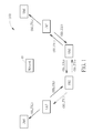
- FIG. 1 is a diagram illustrating a wireless communication system 100 according to an embodiment of the present invention.
- the wireless communication system 100 may preferably include a network 10 and a plurality of user equipment.
- the D2D communication between a transmitting user equipment and a receiving user equipment may be initiated by the network 10 or by the transmitting user equipment.
- the D2D initialization process may include peer discovery, resource allocation and/or connection establishment. However, the method of performing peer discovery or establishing connection does not limit the scope of the present invention.
- SS 1 ⁇ SS 3 represent the synchronization signals used by a transmitting user equipment and a receiving user equipment in the wireless communication system 100.
- TX 1 ⁇ TX 3 and TY 1 ⁇ TY 3 represent the points in time when the transmitting user equipment or the receiving user equipment sends a synchronization signal.
- the detailed operation of the wireless communication system 100 when performing D2D communication will be illustrated in subsequent paragraphs.
- the network 10 may be a universal terrestrial radio access network (UTRAN) of a universal mobile telecommunications system (UMTS) and may include multiple base stations ( node-B, NB).
- UTRAN universal terrestrial radio access network
- UMTS universal mobile telecommunications system
- the network 10 may be an evolved UTRAN (E-UTRAN) of a long term evolution (LTE) system or an LTE-Advanced system and may include multiple evolved base stations (evolved-NB, eNB).
- the network 10 may be any base station of an Institute of Electrical and Electronics Engineers (IEEE) wireless communication system.
- IEEE Institute of Electrical and Electronics Engineers
- each user equipment may include, but is not limited to, a mobile telephone, a personal digital assistant (PDA), a handheld computer, a tablet computer, a nettop computer, or a laptop computers, or any D2D-capable portable electronic device.
- each user equipment may include, but is not limited to, a desktop computer, a setup box, a network appliance, or any D2D-capable stationary electronic device.
- 6 user equipment UE1 ⁇ UE6 are depicted in FIG. 1 .
- the type or the number of the user equipment does not limit the scope of the present invention.
- FIG. 2 is a functional diagram illustrating an electronic device 20 according to an embodiment of the present invention.
- the electronic device 20 including a processing unit 200, a storage unit 210 and a communication interface unit 220, may be used to implement the user equipment UE1 ⁇ UE6.
- the processing unit 200 may be a microprocessor or an application specific integrated circuit (ASIC).
- a program code 214 may be stored in the storage unit 210 and may be accessed or executed by the processing unit 200.
- the storage unit 210 may include, but is not limited to, a subscriber identity module (SIM) card, read-only memory (ROM), flash memory, random-access memory (RAM), a compact disc, a magnetic disc, a hard disc, or an optical storage device.
- SIM subscriber identity module
- ROM read-only memory
- RAM random-access memory
- the communication interface unit 220 may be a wireless transceiver configured to transmit or receive data during D2D communication according to the processing result of the processing unit 200.
- FIG. 3 is a flowchart illustrating a method of performing D2D communication between two user equipment according to an embodiment of the present invention.
- the method depicted in FIG. 3 may be compiled into the program code 214 and includes the following steps:
- the synchronization signals SS 1 ⁇ SS M may be used for synchronizing these two user equipment, the resource groups R 1 ⁇ R M may be used for sending/receiving data, and it may be determined if other user equipment are transmitting the corresponding synchronization signals SS 1 ⁇ SS M at the monitor time TX 1 ⁇ TX M and TY 1 ⁇ TY M , wherein M is an integer larger than 1.
- FIG. 4 is diagram illustrating the operations of steps 300 and 310 according to an embodiment of the present invention.
- the wireless communication system 100 may adopt an orthogonal frequency division multiplexing (OFDM) scheme which divides the available spectrum fragments into chunks of contiguous subcarriers known as resource blocks (RBs) in the frequency-time domain.
- Each resource block is the minimum unit in resource allocation and can only be allocated to a given device at a given point in time.
- the transmission period is gridded into a plurality of contiguous frames of the same length
- the transmission spectrum is gridded into a plurality of contiguous carrier bands F0 ⁇ F6 of the same width.
- Each frame includes 10 sub-frames T0 ⁇ T9.
- the monitor time TX 1 ⁇ TX M and TY 1 ⁇ TY M in each frame correspond to specific points in time during a specific sub-frame among the sub-frames T0 ⁇ T9, wherein TX 1 ⁇ TY 1 , TX 2 ⁇ TY 2 , and TX M ⁇ TY M .
- the resource allocation scheme adopted by the wireless communication system 100 does not limit the scope of the present invention.
- the resource group R 1 is linked to the synchronization signal SS 1 , the monitor time TX 1 and the monitor time TY 1 .
- the resource group R 2 is linked to the synchronization signal SS 2 , the monitor time TX 2 and the monitor time TY 2 .
- the resource group R 3 is linked to the synchronization signal SS 3 , the monitor time TX 3 and the monitor time TY 3 .
- the resource group R 1 includes 4 resource blocks RB 1 which represent the available carrier bands F2-F5 in the sub-frame T2 of each frame, respectively.
- the resource group R 2 includes 5 resource blocks RB 2 which represent the available carrier bands F2 ⁇ F3 in the sub-frame T0 of each frame and the available carrier bands F1 ⁇ F3 in the sub-frame T6 of each frame, respectively.
- the resource group R 3 includes 7 resource blocks RB 3 which represent the available carrier bands F5 ⁇ F6 in the sub-frame T3 of each frame, the available carrier bands F4 ⁇ F6 in the sub-frame T6 of each frame, and the available carrier bands F3 ⁇ F4 in the sub-frame T8 of each frame, respectively.
- each user equipment is configured to detect whether other user equipment are transmitting the synchronization signals SS 1 ⁇ SS 3 in the sub-frames T0 and T5 of each frame.
- the transmitting user equipment is configured to detect the synchronization signals SS 1 ⁇ SS M linked to the resource groups R 1 ⁇ R M at the same monitor time associated with sending data (i.e.
- the transmitting user equipment is configured to detect the synchronization signals SS 1 ⁇ SS M linked to the resource groups R 1 ⁇ R M at the different monitor time associated with transmitting data (i.e. TX 1 ⁇ TX M can be of any order) and detect the synchronization signals SS 1 ⁇ SS M linked to the resource groups R 1 ⁇ R M at the same monitor time associated with receiving data (i.e. TY 1 ⁇ TY M can be of any order).
- the order of the monitor time TX 1 ⁇ TX M or the monitor time TY 1 ⁇ TY M does not limit the scope of the present invention.
- the transmitting user equipment may select a specific synchronization signal from the plurality of synchronization signals. For example, the transmitting user equipment may select an m th synchronization signal from the synchronization signals SS 1 ⁇ SS M , wherein m is a positive integer and 1 ⁇ m ⁇ M.
- the transmitting user equipment is configured to determine if the selected synchronization signal is being transmitted by other user equipment. More specifically, the transmitting user equipment is configured to detect the selected m th synchronization signal at the monitor time TX 1 ⁇ TX M and the monitor time TY 1 ⁇ TY M during each frame.
- step 330 If the transmitting user equipment does not detect the selected m th synchronization signal sent by other user equipment at the monitor time TX m and the monitor time TY m during a first frame, it can be determined in step 330 that the m th synchronization signal is not being used by other user equipment for sending data or receiving data.
- step 350 is executed so that the transmitting user equipment may claim a corresponding resource group by broadcasting the selected synchronization signal.
- the transmitting user equipment may broadcast the m th synchronization signal SS m at the monitor time TX m during a second frame which occurs immediately after the first frame in order to inform other user equipment that the m th resource group R m has been claimed.
- step 330 is executed for selecting another synchronization signal different from the previously selected synchronization signal from the plurality of synchronization signals.
- the value of m may be updated to any value between 1 and M except the original m.
- Steps 340 and 330 may be repeatedly executed until it can be determined that the selected synchronization signal is not being used by other user equipment for sending data or receiving data.
- step 350 is executed so that the transmitting user equipment may claim a corresponding resource group by broadcasting the selected synchronization signal.
- step 360 is executed so that the transmitting user equipment can verify if other user equipment is using the m th resource group R m .
- step 360 If it is determined in step 360 that the m th resource group R m is currently being used by other user equipment, the transmitting user equipment is configured to abandon the claimed m th resource group R m and select/verify another synchronization signal in steps 340 and 330. If it is determined in step 360 that the m th resource group R m is not being used by other user equipment, step 350 is then be executed so that the transmitting user equipment may send data using the claimed m th resource group R m .
- the receiving user equipment is configured to determine if a synchronization signal can be received from the transmitting user equipment at a corresponding first monitor time. For example, the receiving user equipment may determine if the m th synchronization signal SS m can be detected at the monitor time TX m during a third frame.
- the third frame may be any frame that occurs after the second frame, which means the receiving user equipment is configured to periodically detect the synchronization signal during each subsequent frame.
- step 390 is then executed so that the receiving user equipment may receive data using the m th resource group R m and broadcast the m th synchronization signal SS m at the monitor time TY m during a fourth frame which occurs immediately after the third frame. This way, other user equipment can be informed that the m th resource group R m is currently being used for receiving data.
- the user equipment UE1 If the user equipment UE1 has successfully claimed the resource group R 1 for sending data to the user equipment UE2, the user equipment UE1 is configured to broadcast the 1 st synchronization signal SS 1 to the neighboring user equipment UE2 and UE5 at the monitor time TX 1 in each subsequent frame during the D2D communication. After detecting the 1 st synchronization signal SS 1 at the monitor time TX 1 in a current frame, the user equipment UE2 is configured to receive data from the user equipment UE1 using the 1 st resource group R 1 and broadcast the 1 st synchronization signal SS 1 to the neighboring user equipment UE1 and UE3 at the monitor time TY 1 in each subsequent frame during the D2D communication.
- the user equipment UE3 When the user equipment UE3 intends to perform D2D communication with the user equipment UE4 but detects the 1 st synchronization signal SS 1 at the monitor time TY 1 in a current frame, it can be informed that the resource group R 1 is currently being used for receiving data by other user equipment. Therefore, the user equipment UE3 is configured to send data to the user equipment UE4 using the 2 nd resource group R 2 (which may be claimed after executing steps 320-370) and broadcast the 2 nd synchronization signal SS 2 to the neighboring user equipment UE2 and UE4 at the monitor time TX 2 in each subsequent frame during the D2D communication.
- the 2 nd resource group R 2 which may be claimed after executing steps 320-370
- the user equipment UE5 When the user equipment UE5 intends to perform D2D communication with the user equipment UE6 but detects the 1 st synchronization signal SS 1 at the monitor time TX 1 in a current frame, it can be informed that the resource group R 1 is currently being used for sending data by other user equipment. Therefore, the user equipment UE5 is configured to send data to the user equipment UE6 using the 3 rd resource group R 3 (which may be claimed after executing steps 320-370) and broadcast the 3 rd synchronization signal SS 3 to the neighboring user equipment UE1 and UE6 at the monitor time TX 3 in each subsequent frame during the D2D communication.
- the 3 rd resource group R 3 which may be claimed after executing steps 320-370
- carrier sensing technology is used for detecting synchronization signals so that the user equipment may determine if a resource group is available for D2D communication.
- the specific user equipment may periodically broadcast a corresponding synchronization signal for informing other user equipment that the specific resource group has been claimed and is currently unavailable, thereby preventing data collision.
- the specific user equipment may continuously use the specific resource group during the D2D communication without frequently performing CSMA/CD or CSMA/CA for resource allocation. After completing the D2D communication, the specific user equipment may stop broadcasting the corresponding synchronization signal, thereby releasing the specific resource group.
- the present invention can provide a method of resource allocation in order to perform D2D communication with low transmission delay, high spectrum usage and high network coverage.
Landscapes
- Engineering & Computer Science (AREA)
- Computer Networks & Wireless Communication (AREA)
- Signal Processing (AREA)
- Mobile Radio Communication Systems (AREA)
Abstract
Description
- The present invention is related to a method of performing device-to-device communication between two user equipment related wireless communication system by monitoring synchronization signals using carrier sensing technology.
- In a wireless communication system, two devices may communicate with each other via a base station, or directly using device-to-device (D2D) technology. The D2D technology may adopt two modes for resource allocation: network mode or client mode.
- When two devices in coverage of a base station intend to perform D2D communication in the network mode, the base station is configured to allocate necessary resources to the two devices. However, if the base station is overloaded or has insufficient resources, transmission delay may influence the efficiency of D2D communication. Also, it is not possible to perform D2D communication in the network mode when the two devices are out of coverage of the base station.
- When two devices intend to perform D2D communication in the client mode, a specific resource is selected from a resource pool. Uncensored by any base station, a media access control method is required in order to avoid data collision when the two devices contend for D2D resources. Such media access control method may include, but is not limited to, a carrier sense multiple access/collision detection (CSMA/CD) scheme or a carrier sense multiple access/collision avoidance (CSMA/CA) scheme. In a prior art D2D communication method, a device performs carrier sensing by monitoring data transmitted by other devices on the network, thereby lowering the chance of data collision. However, for the periodic transmission of D2D voice communications, carrier sensing is not an efficient way of resource allocation. Also, hidden node problem exists when an ad-hoc wireless communication system performs D2D communication in the client mode. Hidden node problem may cause data collision when a first device and a second device, both located out of the communication range of each other, intend to send data to a third device at the same time. Therefore, there is a need for a method of resource allocation in order to perform D2D communication with low transmission delay, high spectrum usage and high network coverage.
- The present invention aims at providing a method of performing device-to-device communication between a first user equipment and a second user equipment in a wireless communication system with low transmission delay, high spectrum usage and high network coverage
- This is achieved by a method of performing device-to-device communication between a first user equipment and a second user equipment in a wireless communication system according to claim 1 and a wireless communication system according to
claim 10. The dependent claims pertain to corresponding further developments and improvements. - As will be seen more clearly from the detailed description following below, the claimed method of performing device-to-device communication between a first user equipment and a second user equipment in a wireless communication system includes providing a plurality of resource groups and a plurality of synchronization signals for use in the wireless communication system; setting a first monitor time associated with sending data and a second monitor time associated with receiving data; linking a first resource group among the plurality of resource groups to the first monitor time, the second monitor time, and a first synchronization signal among the plurality of synchronization signals; the first user equipment determining if the first synchronization signal is being transmitted by a third user equipment of the wireless communication system; and the first user equipment claiming the first resource group by broadcasting the first synchronization signal after determining that the first synchronization signal is not being transmitted by the third user equipment.
- In the following, the invention is further illustrated by way of example, taking reference to the accompanying drawings.
-
FIG. 1 is a diagram illustrating a wireless communication system according to an embodiment of the present invention. -
FIG. 2 is a functional diagram illustrating an electronic device according to an embodiment of the present invention. -
FIG. 3 is a flowchart illustrating a method of performing device-to-device communication between two user equipment according to an embodiment of the present invention. -
FIG. 4 is diagram illustrating the operations of device-to-device communication according to an embodiment of the present invention. -
FIG. 1 is a diagram illustrating awireless communication system 100 according to an embodiment of the present invention. Thewireless communication system 100 may preferably include anetwork 10 and a plurality of user equipment. The D2D communication between a transmitting user equipment and a receiving user equipment may be initiated by thenetwork 10 or by the transmitting user equipment. The D2D initialization process may include peer discovery, resource allocation and/or connection establishment. However, the method of performing peer discovery or establishing connection does not limit the scope of the present invention. - In
FIG. 1 , SS1∼SS3 represent the synchronization signals used by a transmitting user equipment and a receiving user equipment in thewireless communication system 100. TX1~TX3 and TY1∼TY3 represent the points in time when the transmitting user equipment or the receiving user equipment sends a synchronization signal. The detailed operation of thewireless communication system 100 when performing D2D communication will be illustrated in subsequent paragraphs. - In an embodiment of the present invention, the
network 10 may be a universal terrestrial radio access network (UTRAN) of a universal mobile telecommunications system (UMTS) and may include multiple base stations (node-B, NB). In another embodiment of the present invention, thenetwork 10 may be an evolved UTRAN (E-UTRAN) of a long term evolution (LTE) system or an LTE-Advanced system and may include multiple evolved base stations (evolved-NB, eNB). In another embodiment of the present invention, thenetwork 10 may be any base station of an Institute of Electrical and Electronics Engineers (IEEE) wireless communication system. However, the type of thenetwork 10 does not limit the scope of the present invention. - In an embodiment of the present invention, each user equipment may include, but is not limited to, a mobile telephone, a personal digital assistant (PDA), a handheld computer, a tablet computer, a nettop computer, or a laptop computers, or any D2D-capable portable electronic device. In another embodiment of the present invention, each user equipment may include, but is not limited to, a desktop computer, a setup box, a network appliance, or any D2D-capable stationary electronic device. For illustrative purpose, 6 user equipment UE1∼UE6 are depicted in
FIG. 1 . However, the type or the number of the user equipment does not limit the scope of the present invention. -
FIG. 2 is a functional diagram illustrating anelectronic device 20 according to an embodiment of the present invention. Theelectronic device 20, including aprocessing unit 200, astorage unit 210 and acommunication interface unit 220, may be used to implement the user equipment UE1∼UE6. Theprocessing unit 200 may be a microprocessor or an application specific integrated circuit (ASIC). Aprogram code 214 may be stored in thestorage unit 210 and may be accessed or executed by theprocessing unit 200. In an embodiment of the present invention, thestorage unit 210 may include, but is not limited to, a subscriber identity module (SIM) card, read-only memory (ROM), flash memory, random-access memory (RAM), a compact disc, a magnetic disc, a hard disc, or an optical storage device. Thecommunication interface unit 220 may be a wireless transceiver configured to transmit or receive data during D2D communication according to the processing result of theprocessing unit 200. -
FIG. 3 is a flowchart illustrating a method of performing D2D communication between two user equipment according to an embodiment of the present invention. The method depicted inFIG. 3 may be compiled into theprogram code 214 and includes the following steps: - Step 300:
- provide a plurality of resource groups and a plurality of synchronization signals, and set a plurality of first monitor time associated with sending data and a plurality of second monitor time associated with receiving data; execute
step 310. - Step 310:
- link each resource group to a corresponding synchronization signal, a corresponding first monitor time and a corresponding second monitor time; execute
step 320. - Step 320:
- the transmitting user equipment selects a specific synchronization signal from the plurality of synchronization signals; execute
step 330. - Step 330:
- the transmitting user equipment determines if the selected synchronization signal is being transmitted by other user equipment; if yes, execute
step 340; if no, executestep 350. - Step 340:
- the transmitting user equipment selects another synchronization signal different from the previously selected synchronization signal from the plurality of synchronization signals; execute
step 330. - Step 350:
- the transmitting user equipment broadcasts the selected synchronization signal at a corresponding first monitor time for claiming a corresponding resource group; execute
step 360. - Step 360:
- the transmitting user equipment determines if other user equipment is using the claimed resource group; if yes, execute
step 340; if no, executestep 370. - Step 370:
- the transmitting user equipment sends data using the claimed resource group; execute
step 380. - Step 380:
- the receiving user equipment determines if a synchronization signal can be received from the transmitting user equipment at a corresponding first monitor time; if yes, execute
step 390; if no, executestep 380. - Step 390:
- the receiving user equipment receives data using a resource group associated with the received synchronization signal and broadcasts the received synchronization signal at a corresponding second monitor time.
- In
steps wireless communication system 100, the synchronization signals SS1∼SSM may be used for synchronizing these two user equipment, the resource groups R1∼RM may be used for sending/receiving data, and it may be determined if other user equipment are transmitting the corresponding synchronization signals SS1∼SSM at the monitor time TX1∼TXM and TY1∼TYM, wherein M is an integer larger than 1. -
FIG. 4 is diagram illustrating the operations ofsteps wireless communication system 100 may adopt an orthogonal frequency division multiplexing (OFDM) scheme which divides the available spectrum fragments into chunks of contiguous subcarriers known as resource blocks (RBs) in the frequency-time domain. Each resource block is the minimum unit in resource allocation and can only be allocated to a given device at a given point in time. In the embodiment illustrated inFIG. 4 , the transmission period is gridded into a plurality of contiguous frames of the same length, and the transmission spectrum is gridded into a plurality of contiguous carrier bands F0∼F6 of the same width. Each frame includes 10 sub-frames T0∼T9. The monitor time TX1∼TXM and TY1∼TYM in each frame correspond to specific points in time during a specific sub-frame among the sub-frames T0∼T9, wherein TX1≠TY1, TX2≠TY2, and TXM≠TYM. However, the resource allocation scheme adopted by thewireless communication system 100 does not limit the scope of the present invention. -
FIG. 4 depicts an embodiment of M=3 in which thewireless communication system 100 may use 3 resource groups R1∼R3 each including one or multiple resource blocks. The resource group R1 is linked to the synchronization signal SS1, the monitor time TX1 and the monitor time TY1. The resource group R2 is linked to the synchronization signal SS2, the monitor time TX2 and the monitor time TY2. The resource group R3 is linked to the synchronization signal SS3, the monitor time TX3 and the monitor time TY3. The resource group R1 includes 4 resource blocks RB1 which represent the available carrier bands F2-F5 in the sub-frame T2 of each frame, respectively. The resource group R2 includes 5 resource blocks RB2 which represent the available carrier bands F2~F3 in the sub-frame T0 of each frame and the available carrier bands F1∼F3 in the sub-frame T6 of each frame, respectively. The resource group R3 includes 7 resource blocks RB3 which represent the available carrier bands F5~F6 in the sub-frame T3 of each frame, the available carrier bands F4~F6 in the sub-frame T6 of each frame, and the available carrier bands F3~F4 in the sub-frame T8 of each frame, respectively. - If the monitor time TX1∼TX3 is provided to correspond to the sub-frame T0 and the monitor time TY1∼TY3 is provided to correspond to the sub-frame T5 in
step 300, each user equipment is configured to detect whether other user equipment are transmitting the synchronization signals SS1∼SS3 in the sub-frames T0 and T5 of each frame. In an embodiment of the present invention, the transmitting user equipment is configured to detect the synchronization signals SS1∼SSM linked to the resource groups R1∼RM at the same monitor time associated with sending data (i.e. TX1=TX2=...=TXM) and detect the synchronization signals SS1∼SSM linked to the resource groups R1∼RM at the same monitor time associated with receiving data (i.e. TY1=TY2=...=TYM). In another embodiment of the present invention, the transmitting user equipment is configured to detect the synchronization signals SS1∼SSM linked to the resource groups R1∼RM at the different monitor time associated with transmitting data (i.e. TX1∼TXM can be of any order) and detect the synchronization signals SS1∼SSM linked to the resource groups R1∼RM at the same monitor time associated with receiving data (i.e. TY1∼TYM can be of any order). However, the order of the monitor time TX1∼TXM or the monitor time TY1∼TYM does not limit the scope of the present invention. - In
step 320, the transmitting user equipment may select a specific synchronization signal from the plurality of synchronization signals. For example, the transmitting user equipment may select an mth synchronization signal from the synchronization signals SS1∼SSM, wherein m is a positive integer and 1 ≦ m ≦ M. - In
step 330, the transmitting user equipment is configured to determine if the selected synchronization signal is being transmitted by other user equipment. More specifically, the transmitting user equipment is configured to detect the selected mth synchronization signal at the monitor time TX1∼TXM and the monitor time TY1∼TYM during each frame. - If the transmitting user equipment does not detect the selected mth synchronization signal sent by other user equipment at the monitor time TXm and the monitor time TYm during a first frame, it can be determined in
step 330 that the mth synchronization signal is not being used by other user equipment for sending data or receiving data. Next,step 350 is executed so that the transmitting user equipment may claim a corresponding resource group by broadcasting the selected synchronization signal. For example, the transmitting user equipment may broadcast the mth synchronization signal SSm at the monitor time TXm during a second frame which occurs immediately after the first frame in order to inform other user equipment that the mth resource group Rm has been claimed. - On the other hand, if the transmitting user equipment detects the selected mth synchronization signal sent by other user equipment at the monitor time TXm or the monitor time TYm during a first frame, it can be determined in
step 330 that the mth synchronization signal is currently being used by other user equipment for sending data or receiving data. Next,step 340 is executed for selecting another synchronization signal different from the previously selected synchronization signal from the plurality of synchronization signals. For example, the value of m may be updated to any value between 1 and M except the original m.Steps step 350 is executed so that the transmitting user equipment may claim a corresponding resource group by broadcasting the selected synchronization signal. - If the
steps step 340 and both claim the same resource group instep 350. If the two user equipment both send data using the same resource group, data collision may occur. Therefore, after claiming the mth resource group Rm by broadcasting the mth synchronization signal SSm instep 350,step 360 is executed so that the transmitting user equipment can verify if other user equipment is using the mth resource group Rm. If it is determined instep 360 that the mth resource group Rm is currently being used by other user equipment, the transmitting user equipment is configured to abandon the claimed mth resource group Rm and select/verify another synchronization signal insteps step 360 that the mth resource group Rm is not being used by other user equipment,step 350 is then be executed so that the transmitting user equipment may send data using the claimed mth resource group Rm. - In
step 380, the receiving user equipment is configured to determine if a synchronization signal can be received from the transmitting user equipment at a corresponding first monitor time. For example, the receiving user equipment may determine if the mth synchronization signal SSm can be detected at the monitor time TXm during a third frame. The third frame may be any frame that occurs after the second frame, which means the receiving user equipment is configured to periodically detect the synchronization signal during each subsequent frame. If the mth synchronization signal SSm can be detected at the monitor time TXm during the third frame,step 390 is then executed so that the receiving user equipment may receive data using the mth resource group Rm and broadcast the mth synchronization signal SSm at the monitor time TYm during a fourth frame which occurs immediately after the third frame. This way, other user equipment can be informed that the mth resource group Rm is currently being used for receiving data. - Reference is made to
FIG. 1 andFIG. 3 . If the user equipment UE1 has successfully claimed the resource group R1 for sending data to the user equipment UE2, the user equipment UE1 is configured to broadcast the 1st synchronization signal SS1 to the neighboring user equipment UE2 and UE5 at the monitor time TX1 in each subsequent frame during the D2D communication. After detecting the 1st synchronization signal SS1 at the monitor time TX1 in a current frame, the user equipment UE2 is configured to receive data from the user equipment UE1 using the 1st resource group R1 and broadcast the 1st synchronization signal SS1 to the neighboring user equipment UE1 and UE3 at the monitor time TY1 in each subsequent frame during the D2D communication. When the user equipment UE3 intends to perform D2D communication with the user equipment UE4 but detects the 1st synchronization signal SS1 at the monitor time TY1 in a current frame, it can be informed that the resource group R1 is currently being used for receiving data by other user equipment. Therefore, the user equipment UE3 is configured to send data to the user equipment UE4 using the 2nd resource group R2 (which may be claimed after executing steps 320-370) and broadcast the 2nd synchronization signal SS2 to the neighboring user equipment UE2 and UE4 at the monitor time TX2 in each subsequent frame during the D2D communication. When the user equipment UE5 intends to perform D2D communication with the user equipment UE6 but detects the 1st synchronization signal SS1 at the monitor time TX1 in a current frame, it can be informed that the resource group R1 is currently being used for sending data by other user equipment. Therefore, the user equipment UE5 is configured to send data to the user equipment UE6 using the 3rd resource group R3 (which may be claimed after executing steps 320-370) and broadcast the 3rd synchronization signal SS3 to the neighboring user equipment UE1 and UE6 at the monitor time TX3 in each subsequent frame during the D2D communication. - In the present invention, carrier sensing technology is used for detecting synchronization signals so that the user equipment may determine if a resource group is available for D2D communication. During the D2D communication when a specific user equipment is sending data using a specific resource group, the specific user equipment may periodically broadcast a corresponding synchronization signal for informing other user equipment that the specific resource group has been claimed and is currently unavailable, thereby preventing data collision. The specific user equipment may continuously use the specific resource group during the D2D communication without frequently performing CSMA/CD or CSMA/CA for resource allocation. After completing the D2D communication, the specific user equipment may stop broadcasting the corresponding synchronization signal, thereby releasing the specific resource group. Also, during the D2D communication when the specific user equipment is receiving data using the specific resource group, the specific user equipment may periodically broadcast a corresponding synchronization signal for informing other user equipment that the specific resource group has been claimed and is currently unavailable, thereby preventing the hidden node problem. Therefore, the present invention can provide a method of resource allocation in order to perform D2D communication with low transmission delay, high spectrum usage and high network coverage.
Claims (10)
- A method of performing device-to-device communication between a first user equipment (20) and a second user equipment (20) in a wireless communication system (100), the method characterized in that it comprises the steps of:providing a plurality of resource groups and a plurality of synchronization signals for use in the wireless communication system;setting a first monitor time associated with sending data and a second monitor time associated with receiving data;linking a first resource group among the plurality of resource groups to the first monitor time, the second monitor time, and a first synchronization signal among the plurality of synchronization signals;the first user equipment (20) determining if the first synchronization signal is being transmitted by a third user equipment (20) of the wireless communication system; andthe first user equipment (20) claiming the first resource group by broadcasting the first synchronization signal after determining that the first synchronization signal is not being transmitted by the third user equipment (20).
- The method of claim 1, characterized in that:the first user equipment (20) determines if the first synchronization signal is being transmitted by the third user equipment (20) at the first monitor time and at the second monitor time during a first frame;the first user equipment (20) claims the first resource group by broadcasting the first synchronization signal at the first monitor time during a second frame after determining that the first synchronization signal is not being transmitted by the third user equipment (20) at the first monitor time and at the second monitor time during the first frame; andthe second frame occurs immediately after the first frame.
- The method of claim 1, further characterized by comprising the further step of:the first user equipment (20) determining if the claimed first resource group is currently being used by a fourth user equipment (20) of the wireless communication system by monitoring the plurality of resource groups after claiming the first resource group; andthe first user equipment (20) sending data to the second user equipment (20) using the claimed first resource group after determining that the claimed first resource group is not being used by the fourth user equipment (20).
- The method of claim 3, characterized in that:the first user equipment (20) determines if the first synchronization signal is being transmitted by the fourth user equipment (20) at the first monitor time during a first frame;the first user equipment (20) determines if the claimed first resource group is currently being used by the fourth user equipment (20) by monitoring the plurality of resource groups during a second frame; andthe second frame occurs after the first frame.
- The method of any of claims 3-4, further characterized by comprising the further step of:the first user equipment (20) broadcasting the first synchronization signal at the first monitor time during each frame which occurs within a period when the first user equipment (20) sends data to the second user equipment (20) using the claimed first resource group.
- The method of any of claims 3-5, further characterized by comprising the further step of:the second user equipment (20) receiving data from the first user equipment (20) using the first resource group after detecting the first synchronization signal at the first monitor time during a first frame; andthe second user equipment (20) broadcasting the first synchronization signal at the second monitor time during each frame which occurs within a period when the second user equipment (20) receives data from the first user equipment (20) using the first resource group.
- The method of any of claims 3-6, further characterized by comprising the further step of:the first user equipment (20) synchronizing with the second user equipment (20) using the first synchronization signal before sending data to the second user equipment (20) using the first resource group.
- The method of any of claims 1-7, characterized in that the first user equipment (20) determines if the first synchronization signal is being transmitted by the third user equipment (20) at the first monitor time and the second monitor time during a first frame, and the method further comprising:setting third monitor time associated with sending data and fourth monitor time associated with receiving data;linking a second resource group among the plurality of resource groups to the third monitor time, the fourth monitor time, and a second synchronization signal among the plurality of synchronization signals;the first user equipment (20) determining if the second synchronization signal is being transmitted by a fifth user equipment (20) of the wireless communication system at the third monitor time and the fourth monitor time during a second frame which occurs immediately after the first frame after determining that the first synchronization signal is being transmitted by the third user equipment (20) at the first monitor time or the second monitor time during the first frame.
- The method of any of claims 1-8, characterized in that each resource group includes one or multiple resource blocks of an orthogonal frequency division multiplexing scheme.
- A wireless communication system (100) comprising a first user equipment (20) and a second user equipment (20) capable of carrying out the method according to any of claims 1-9.
Applications Claiming Priority (2)
| Application Number | Priority Date | Filing Date | Title |
|---|---|---|---|
| US201461980586P | 2014-04-17 | 2014-04-17 | |
| TW103126634A TWI549557B (en) | 2014-04-17 | 2014-08-04 | Method for device-to-device communication between two communication devices |
Publications (2)
| Publication Number | Publication Date |
|---|---|
| EP2934054A1 true EP2934054A1 (en) | 2015-10-21 |
| EP2934054B1 EP2934054B1 (en) | 2016-06-29 |
Family
ID=52814869
Family Applications (1)
| Application Number | Title | Priority Date | Filing Date |
|---|---|---|---|
| EP15162578.7A Active EP2934054B1 (en) | 2014-04-17 | 2015-04-07 | Method of performing device-to-device communication between two user equipment and related wireless communication system |
Country Status (2)
| Country | Link |
|---|---|
| US (1) | US9635629B2 (en) |
| EP (1) | EP2934054B1 (en) |
Cited By (1)
| Publication number | Priority date | Publication date | Assignee | Title |
|---|---|---|---|---|
| CN106612558A (en) * | 2015-10-27 | 2017-05-03 | 普天信息技术有限公司 | Wireless time-frequency resource conflict resolution method and DMO terminal |
Families Citing this family (6)
| Publication number | Priority date | Publication date | Assignee | Title |
|---|---|---|---|---|
| JP6391806B2 (en) | 2014-04-24 | 2018-09-19 | エルジー エレクトロニクス インコーポレイティド | Synchronization signal transmission method and apparatus for D2D communication in a wireless communication system |
| CN105230099B (en) * | 2014-04-29 | 2019-05-24 | 华为技术有限公司 | A resource multiplexing device, user equipment and method |
| US20160270105A1 (en) * | 2015-03-11 | 2016-09-15 | Qualcomm Incorporated | Access point managed concurrent transmissions |
| CN114286436B (en) * | 2016-06-23 | 2023-06-23 | 中兴通讯股份有限公司 | A method for sending and receiving a synchronization signal, and a communication node |
| WO2018021784A1 (en) * | 2016-07-28 | 2018-02-01 | 엘지전자 주식회사 | Signal transmission/reception method associated with platoon communication in wireless communication system |
| CN110233770B (en) * | 2018-03-06 | 2023-01-06 | 华为技术有限公司 | Network traffic marking and measuring method and node |
Citations (3)
| Publication number | Priority date | Publication date | Assignee | Title |
|---|---|---|---|---|
| WO2013141672A1 (en) * | 2012-03-23 | 2013-09-26 | 엘지전자 주식회사 | Uplink signal transmission method and station device, and uplink signal receiving method and access point device |
| US20140003414A1 (en) * | 2012-06-27 | 2014-01-02 | Nokia Corporation | Method, apparatus, and computer program product for resolving hidden node in synchronized dcf based channel access |
| WO2014011006A1 (en) * | 2012-07-13 | 2014-01-16 | 엘지전자 주식회사 | Method and apparatus for accessing channel using null data packet in wireless lan system |
Family Cites Families (10)
| Publication number | Priority date | Publication date | Assignee | Title |
|---|---|---|---|---|
| US7688846B2 (en) | 2007-10-31 | 2010-03-30 | Motorola, Inc. | Cooperative CSMA mode identification in clustered networks |
| WO2011088619A1 (en) * | 2010-01-22 | 2011-07-28 | Nokia Corporation | Cellular control sensing for multi-cell device-to-device interference control |
| TWI466554B (en) | 2010-03-23 | 2014-12-21 | Acer Inc | Multi-channel media access control method for cognitive radio |
| US9510322B2 (en) | 2010-09-14 | 2016-11-29 | Nokia Technologies Oy | D2D communication procedures: beaconing; broadcast; conflict resolution |
| US9991998B2 (en) * | 2011-11-25 | 2018-06-05 | Avago Technologies General Ip (Singapore) Pte. Ltd. | Ratio resource sharing and contention scheme for device-to-device communication in white space spectrum bands |
| US9143984B2 (en) * | 2012-04-13 | 2015-09-22 | Intel Corporation | Mapping of enhanced physical downlink control channels in a wireless communication network |
| CN103428818B (en) * | 2012-05-24 | 2017-02-15 | 华为技术有限公司 | Terminal device discovery method, device and system |
| EP3136619B1 (en) * | 2012-07-13 | 2020-12-30 | Electronics and Telecommunications Research Institute | Discovery method for device to device communication between terminals |
| CN104904302A (en) * | 2012-09-28 | 2015-09-09 | 美国博通公司 | Methods, devices and computer program products improving device-to-device communication |
| US9277518B2 (en) * | 2013-01-25 | 2016-03-01 | Electronics And Telecommunications Research Institute | Synchronization method and apparatus in device-to-device direct communication |
-
2014
- 2014-12-16 US US14/571,298 patent/US9635629B2/en active Active
-
2015
- 2015-04-07 EP EP15162578.7A patent/EP2934054B1/en active Active
Patent Citations (5)
| Publication number | Priority date | Publication date | Assignee | Title |
|---|---|---|---|---|
| WO2013141672A1 (en) * | 2012-03-23 | 2013-09-26 | 엘지전자 주식회사 | Uplink signal transmission method and station device, and uplink signal receiving method and access point device |
| US20150085836A1 (en) * | 2012-03-23 | 2015-03-26 | Lg Electronics Inc. | Uplink signal transmission method and station device, and uplink signal receiving method and access point device |
| US20140003414A1 (en) * | 2012-06-27 | 2014-01-02 | Nokia Corporation | Method, apparatus, and computer program product for resolving hidden node in synchronized dcf based channel access |
| WO2014011006A1 (en) * | 2012-07-13 | 2014-01-16 | 엘지전자 주식회사 | Method and apparatus for accessing channel using null data packet in wireless lan system |
| EP2874459A1 (en) * | 2012-07-13 | 2015-05-20 | LG Electronics Inc. | Method and apparatus for accessing channel using null data packet in wireless lan system |
Cited By (2)
| Publication number | Priority date | Publication date | Assignee | Title |
|---|---|---|---|---|
| CN106612558A (en) * | 2015-10-27 | 2017-05-03 | 普天信息技术有限公司 | Wireless time-frequency resource conflict resolution method and DMO terminal |
| CN106612558B (en) * | 2015-10-27 | 2019-10-08 | 普天信息技术有限公司 | A kind of wireless running time-frequency resource contention resolution and DMO terminal |
Also Published As
| Publication number | Publication date |
|---|---|
| EP2934054B1 (en) | 2016-06-29 |
| US20150304973A1 (en) | 2015-10-22 |
| US9635629B2 (en) | 2017-04-25 |
Similar Documents
| Publication | Publication Date | Title |
|---|---|---|
| EP2934054B1 (en) | Method of performing device-to-device communication between two user equipment and related wireless communication system | |
| KR101821075B1 (en) | Method and apparatus for control signaling for enabling two-hop orthogonalization for device-to-device broadcasts | |
| CN108271259B (en) | Control channel resource indication method, user equipment and network equipment | |
| EP3310101B1 (en) | D2d synchronization method, user equipment and serving cell | |
| JP5318151B2 (en) | Mobile communication method, radio base station, and mobile station | |
| CN104754524B (en) | A kind of method of group communication, user equipment, base station equipment and system | |
| RU2748223C1 (en) | Signal transmission method, network device and terminal | |
| US10945257B2 (en) | Data sending method, terminal device, and access network device | |
| EP3163956A1 (en) | Wireless communication system | |
| CN110447297B (en) | Terminal and random access preamble transmission method | |
| CN110809311B (en) | Method and apparatus for performing partial subframe transmission | |
| EP2830381B1 (en) | Method for configuring timing resource in device to device communication | |
| US20130084877A1 (en) | Method and apparatus for communicating hidden common enhanced dedicated channel resources | |
| CN108464028B (en) | Frequency band allocation device, method and communication system | |
| EP3637805B1 (en) | Random access methods, network device and terminal | |
| CN105188020A (en) | D2D communication method, user device and base station | |
| CN110771108B (en) | User device, base station, and random access control method | |
| CN104521205A (en) | Transmission and reception method, apparatus and system for enhanced physical downlink control channel | |
| US11700534B2 (en) | Frequency multiplexing of first and second OFDMA transmissions | |
| EP3534661B1 (en) | Internet of vehicles transmission resource acquisition method and terminal | |
| EP3484220B1 (en) | Resource indication method and related device | |
| CN105101240A (en) | Methods and equipment for sending and detecting control information | |
| AU2017258846B2 (en) | Method and apparatus for performing fractional subframe transmission | |
| CN105025567B (en) | Method for device-to-device communication between two communication devices | |
| EP3217745A1 (en) | Method, wireless access device, and user equipment for information transmission |
Legal Events
| Date | Code | Title | Description |
|---|---|---|---|
| PUAI | Public reference made under article 153(3) epc to a published international application that has entered the european phase |
Free format text: ORIGINAL CODE: 0009012 |
|
| AK | Designated contracting states |
Kind code of ref document: A1 Designated state(s): AL AT BE BG CH CY CZ DE DK EE ES FI FR GB GR HR HU IE IS IT LI LT LU LV MC MK MT NL NO PL PT RO RS SE SI SK SM TR |
|
| AX | Request for extension of the european patent |
Extension state: BA ME |
|
| 17P | Request for examination filed |
Effective date: 20151111 |
|
| RBV | Designated contracting states (corrected) |
Designated state(s): AL AT BE BG CH CY CZ DE DK EE ES FI FR GB GR HR HU IE IS IT LI LT LU LV MC MK MT NL NO PL PT RO RS SE SI SK SM TR |
|
| GRAP | Despatch of communication of intention to grant a patent |
Free format text: ORIGINAL CODE: EPIDOSNIGR1 |
|
| RIC1 | Information provided on ipc code assigned before grant |
Ipc: H04W 72/02 20090101AFI20160119BHEP Ipc: H04W 74/08 20090101ALI20160119BHEP |
|
| INTG | Intention to grant announced |
Effective date: 20160205 |
|
| RIN1 | Information on inventor provided before grant (corrected) |
Inventor name: YE, SHIANG-RUNG |
|
| GRAS | Grant fee paid |
Free format text: ORIGINAL CODE: EPIDOSNIGR3 |
|
| GRAA | (expected) grant |
Free format text: ORIGINAL CODE: 0009210 |
|
| AK | Designated contracting states |
Kind code of ref document: B1 Designated state(s): AL AT BE BG CH CY CZ DE DK EE ES FI FR GB GR HR HU IE IS IT LI LT LU LV MC MK MT NL NO PL PT RO RS SE SI SK SM TR |
|
| REG | Reference to a national code |
Ref country code: GB Ref legal event code: FG4D |
|
| REG | Reference to a national code |
Ref country code: CH Ref legal event code: EP |
|
| REG | Reference to a national code |
Ref country code: AT Ref legal event code: REF Ref document number: 809969 Country of ref document: AT Kind code of ref document: T Effective date: 20160715 |
|
| REG | Reference to a national code |
Ref country code: IE Ref legal event code: FG4D |
|
| REG | Reference to a national code |
Ref country code: DE Ref legal event code: R096 Ref document number: 602015000086 Country of ref document: DE |
|
| REG | Reference to a national code |
Ref country code: LT Ref legal event code: MG4D |
|
| PG25 | Lapsed in a contracting state [announced via postgrant information from national office to epo] |
Ref country code: NO Free format text: LAPSE BECAUSE OF FAILURE TO SUBMIT A TRANSLATION OF THE DESCRIPTION OR TO PAY THE FEE WITHIN THE PRESCRIBED TIME-LIMIT Effective date: 20160929 Ref country code: FI Free format text: LAPSE BECAUSE OF FAILURE TO SUBMIT A TRANSLATION OF THE DESCRIPTION OR TO PAY THE FEE WITHIN THE PRESCRIBED TIME-LIMIT Effective date: 20160629 Ref country code: LT Free format text: LAPSE BECAUSE OF FAILURE TO SUBMIT A TRANSLATION OF THE DESCRIPTION OR TO PAY THE FEE WITHIN THE PRESCRIBED TIME-LIMIT Effective date: 20160629 |
|
| REG | Reference to a national code |
Ref country code: NL Ref legal event code: MP Effective date: 20160629 |
|
| PG25 | Lapsed in a contracting state [announced via postgrant information from national office to epo] |
Ref country code: LV Free format text: LAPSE BECAUSE OF FAILURE TO SUBMIT A TRANSLATION OF THE DESCRIPTION OR TO PAY THE FEE WITHIN THE PRESCRIBED TIME-LIMIT Effective date: 20160629 Ref country code: NL Free format text: LAPSE BECAUSE OF FAILURE TO SUBMIT A TRANSLATION OF THE DESCRIPTION OR TO PAY THE FEE WITHIN THE PRESCRIBED TIME-LIMIT Effective date: 20160629 Ref country code: HR Free format text: LAPSE BECAUSE OF FAILURE TO SUBMIT A TRANSLATION OF THE DESCRIPTION OR TO PAY THE FEE WITHIN THE PRESCRIBED TIME-LIMIT Effective date: 20160629 Ref country code: GR Free format text: LAPSE BECAUSE OF FAILURE TO SUBMIT A TRANSLATION OF THE DESCRIPTION OR TO PAY THE FEE WITHIN THE PRESCRIBED TIME-LIMIT Effective date: 20160930 Ref country code: RS Free format text: LAPSE BECAUSE OF FAILURE TO SUBMIT A TRANSLATION OF THE DESCRIPTION OR TO PAY THE FEE WITHIN THE PRESCRIBED TIME-LIMIT Effective date: 20160629 Ref country code: SE Free format text: LAPSE BECAUSE OF FAILURE TO SUBMIT A TRANSLATION OF THE DESCRIPTION OR TO PAY THE FEE WITHIN THE PRESCRIBED TIME-LIMIT Effective date: 20160629 |
|
| REG | Reference to a national code |
Ref country code: AT Ref legal event code: MK05 Ref document number: 809969 Country of ref document: AT Kind code of ref document: T Effective date: 20160629 |
|
| PG25 | Lapsed in a contracting state [announced via postgrant information from national office to epo] |
Ref country code: IT Free format text: LAPSE BECAUSE OF FAILURE TO SUBMIT A TRANSLATION OF THE DESCRIPTION OR TO PAY THE FEE WITHIN THE PRESCRIBED TIME-LIMIT Effective date: 20160629 Ref country code: RO Free format text: LAPSE BECAUSE OF FAILURE TO SUBMIT A TRANSLATION OF THE DESCRIPTION OR TO PAY THE FEE WITHIN THE PRESCRIBED TIME-LIMIT Effective date: 20160629 Ref country code: EE Free format text: LAPSE BECAUSE OF FAILURE TO SUBMIT A TRANSLATION OF THE DESCRIPTION OR TO PAY THE FEE WITHIN THE PRESCRIBED TIME-LIMIT Effective date: 20160629 Ref country code: SK Free format text: LAPSE BECAUSE OF FAILURE TO SUBMIT A TRANSLATION OF THE DESCRIPTION OR TO PAY THE FEE WITHIN THE PRESCRIBED TIME-LIMIT Effective date: 20160629 Ref country code: IS Free format text: LAPSE BECAUSE OF FAILURE TO SUBMIT A TRANSLATION OF THE DESCRIPTION OR TO PAY THE FEE WITHIN THE PRESCRIBED TIME-LIMIT Effective date: 20161029 Ref country code: CZ Free format text: LAPSE BECAUSE OF FAILURE TO SUBMIT A TRANSLATION OF THE DESCRIPTION OR TO PAY THE FEE WITHIN THE PRESCRIBED TIME-LIMIT Effective date: 20160629 |
|
| PG25 | Lapsed in a contracting state [announced via postgrant information from national office to epo] |
Ref country code: AT Free format text: LAPSE BECAUSE OF FAILURE TO SUBMIT A TRANSLATION OF THE DESCRIPTION OR TO PAY THE FEE WITHIN THE PRESCRIBED TIME-LIMIT Effective date: 20160629 Ref country code: SM Free format text: LAPSE BECAUSE OF FAILURE TO SUBMIT A TRANSLATION OF THE DESCRIPTION OR TO PAY THE FEE WITHIN THE PRESCRIBED TIME-LIMIT Effective date: 20160629 Ref country code: ES Free format text: LAPSE BECAUSE OF FAILURE TO SUBMIT A TRANSLATION OF THE DESCRIPTION OR TO PAY THE FEE WITHIN THE PRESCRIBED TIME-LIMIT Effective date: 20160629 Ref country code: BE Free format text: LAPSE BECAUSE OF FAILURE TO SUBMIT A TRANSLATION OF THE DESCRIPTION OR TO PAY THE FEE WITHIN THE PRESCRIBED TIME-LIMIT Effective date: 20160629 Ref country code: PT Free format text: LAPSE BECAUSE OF FAILURE TO SUBMIT A TRANSLATION OF THE DESCRIPTION OR TO PAY THE FEE WITHIN THE PRESCRIBED TIME-LIMIT Effective date: 20161031 Ref country code: PL Free format text: LAPSE BECAUSE OF FAILURE TO SUBMIT A TRANSLATION OF THE DESCRIPTION OR TO PAY THE FEE WITHIN THE PRESCRIBED TIME-LIMIT Effective date: 20160629 |
|
| REG | Reference to a national code |
Ref country code: FR Ref legal event code: PLFP Year of fee payment: 3 |
|
| REG | Reference to a national code |
Ref country code: DE Ref legal event code: R097 Ref document number: 602015000086 Country of ref document: DE |
|
| PG25 | Lapsed in a contracting state [announced via postgrant information from national office to epo] |
Ref country code: DK Free format text: LAPSE BECAUSE OF FAILURE TO SUBMIT A TRANSLATION OF THE DESCRIPTION OR TO PAY THE FEE WITHIN THE PRESCRIBED TIME-LIMIT Effective date: 20160629 |
|
| 26N | No opposition filed |
Effective date: 20170330 |
|
| PLBE | No opposition filed within time limit |
Free format text: ORIGINAL CODE: 0009261 |
|
| STAA | Information on the status of an ep patent application or granted ep patent |
Free format text: STATUS: NO OPPOSITION FILED WITHIN TIME LIMIT |
|
| PG25 | Lapsed in a contracting state [announced via postgrant information from national office to epo] |
Ref country code: SI Free format text: LAPSE BECAUSE OF FAILURE TO SUBMIT A TRANSLATION OF THE DESCRIPTION OR TO PAY THE FEE WITHIN THE PRESCRIBED TIME-LIMIT Effective date: 20160629 Ref country code: BG Free format text: LAPSE BECAUSE OF FAILURE TO SUBMIT A TRANSLATION OF THE DESCRIPTION OR TO PAY THE FEE WITHIN THE PRESCRIBED TIME-LIMIT Effective date: 20160929 |
|
| REG | Reference to a national code |
Ref country code: IE Ref legal event code: MM4A |
|
| PG25 | Lapsed in a contracting state [announced via postgrant information from national office to epo] |
Ref country code: MC Free format text: LAPSE BECAUSE OF FAILURE TO SUBMIT A TRANSLATION OF THE DESCRIPTION OR TO PAY THE FEE WITHIN THE PRESCRIBED TIME-LIMIT Effective date: 20160629 |
|
| PG25 | Lapsed in a contracting state [announced via postgrant information from national office to epo] |
Ref country code: LU Free format text: LAPSE BECAUSE OF NON-PAYMENT OF DUE FEES Effective date: 20170407 |
|
| REG | Reference to a national code |
Ref country code: FR Ref legal event code: PLFP Year of fee payment: 4 |
|
| PG25 | Lapsed in a contracting state [announced via postgrant information from national office to epo] |
Ref country code: IE Free format text: LAPSE BECAUSE OF NON-PAYMENT OF DUE FEES Effective date: 20170407 |
|
| PG25 | Lapsed in a contracting state [announced via postgrant information from national office to epo] |
Ref country code: MT Free format text: LAPSE BECAUSE OF NON-PAYMENT OF DUE FEES Effective date: 20170407 |
|
| PG25 | Lapsed in a contracting state [announced via postgrant information from national office to epo] |
Ref country code: AL Free format text: LAPSE BECAUSE OF FAILURE TO SUBMIT A TRANSLATION OF THE DESCRIPTION OR TO PAY THE FEE WITHIN THE PRESCRIBED TIME-LIMIT Effective date: 20160629 |
|
| REG | Reference to a national code |
Ref country code: CH Ref legal event code: PL |
|
| PG25 | Lapsed in a contracting state [announced via postgrant information from national office to epo] |
Ref country code: CH Free format text: LAPSE BECAUSE OF NON-PAYMENT OF DUE FEES Effective date: 20180430 Ref country code: LI Free format text: LAPSE BECAUSE OF NON-PAYMENT OF DUE FEES Effective date: 20180430 |
|
| PG25 | Lapsed in a contracting state [announced via postgrant information from national office to epo] |
Ref country code: HU Free format text: LAPSE BECAUSE OF FAILURE TO SUBMIT A TRANSLATION OF THE DESCRIPTION OR TO PAY THE FEE WITHIN THE PRESCRIBED TIME-LIMIT; INVALID AB INITIO Effective date: 20150407 |
|
| PG25 | Lapsed in a contracting state [announced via postgrant information from national office to epo] |
Ref country code: CY Free format text: LAPSE BECAUSE OF FAILURE TO SUBMIT A TRANSLATION OF THE DESCRIPTION OR TO PAY THE FEE WITHIN THE PRESCRIBED TIME-LIMIT Effective date: 20160629 |
|
| PG25 | Lapsed in a contracting state [announced via postgrant information from national office to epo] |
Ref country code: MK Free format text: LAPSE BECAUSE OF FAILURE TO SUBMIT A TRANSLATION OF THE DESCRIPTION OR TO PAY THE FEE WITHIN THE PRESCRIBED TIME-LIMIT Effective date: 20160629 |
|
| REG | Reference to a national code |
Ref country code: DE Ref legal event code: R082 Ref document number: 602015000086 Country of ref document: DE Representative=s name: STRAUS, ALEXANDER, DIPL.-CHEM.UNIV. DR.PHIL., DE Ref country code: DE Ref legal event code: R082 Ref document number: 602015000086 Country of ref document: DE Representative=s name: 2K PATENT- UND RECHTSANWAELTE PARTNERSCHAFT MB, DE |
|
| PG25 | Lapsed in a contracting state [announced via postgrant information from national office to epo] |
Ref country code: TR Free format text: LAPSE BECAUSE OF FAILURE TO SUBMIT A TRANSLATION OF THE DESCRIPTION OR TO PAY THE FEE WITHIN THE PRESCRIBED TIME-LIMIT Effective date: 20160629 |
|
| REG | Reference to a national code |
Ref country code: DE Ref legal event code: R082 Ref document number: 602015000086 Country of ref document: DE Representative=s name: STRAUS, ALEXANDER, DIPL.-CHEM.UNIV. DR.PHIL., DE |
|
| PGFP | Annual fee paid to national office [announced via postgrant information from national office to epo] |
Ref country code: FR Payment date: 20250310 Year of fee payment: 11 |
|
| PGFP | Annual fee paid to national office [announced via postgrant information from national office to epo] |
Ref country code: GB Payment date: 20250313 Year of fee payment: 11 |
|
| PGFP | Annual fee paid to national office [announced via postgrant information from national office to epo] |
Ref country code: DE Payment date: 20250311 Year of fee payment: 11 |