EP2934048A2 - Communication device for handling uplink power control - Google Patents
Communication device for handling uplink power control Download PDFInfo
- Publication number
- EP2934048A2 EP2934048A2 EP15163972.1A EP15163972A EP2934048A2 EP 2934048 A2 EP2934048 A2 EP 2934048A2 EP 15163972 A EP15163972 A EP 15163972A EP 2934048 A2 EP2934048 A2 EP 2934048A2
- Authority
- EP
- European Patent Office
- Prior art keywords
- power level
- base station
- channel power
- subframe
- data channel
- Prior art date
- Legal status (The legal status is an assumption and is not a legal conclusion. Google has not performed a legal analysis and makes no representation as to the accuracy of the status listed.)
- Granted
Links
Images


Classifications
-
- H—ELECTRICITY
- H04—ELECTRIC COMMUNICATION TECHNIQUE
- H04W—WIRELESS COMMUNICATION NETWORKS
- H04W52/00—Power management, e.g. Transmission Power Control [TPC] or power classes
- H04W52/04—Transmission power control [TPC]
- H04W52/06—TPC algorithms
- H04W52/14—Separate analysis of uplink or downlink
- H04W52/146—Uplink power control
-
- H—ELECTRICITY
- H04—ELECTRIC COMMUNICATION TECHNIQUE
- H04W—WIRELESS COMMUNICATION NETWORKS
- H04W52/00—Power management, e.g. Transmission Power Control [TPC] or power classes
- H04W52/04—Transmission power control [TPC]
- H04W52/06—TPC algorithms
- H04W52/16—Deriving transmission power values from another channel
-
- H—ELECTRICITY
- H04—ELECTRIC COMMUNICATION TECHNIQUE
- H04W—WIRELESS COMMUNICATION NETWORKS
- H04W52/00—Power management, e.g. Transmission Power Control [TPC] or power classes
- H04W52/04—Transmission power control [TPC]
- H04W52/18—TPC being performed according to specific parameters
- H04W52/24—TPC being performed according to specific parameters using SIR [Signal to Interference Ratio] or other wireless path parameters
- H04W52/246—TPC being performed according to specific parameters using SIR [Signal to Interference Ratio] or other wireless path parameters where the output power of a terminal is based on a path parameter calculated in said terminal
-
- H—ELECTRICITY
- H04—ELECTRIC COMMUNICATION TECHNIQUE
- H04W—WIRELESS COMMUNICATION NETWORKS
- H04W52/00—Power management, e.g. Transmission Power Control [TPC] or power classes
- H04W52/04—Transmission power control [TPC]
- H04W52/30—Transmission power control [TPC] using constraints in the total amount of available transmission power
- H04W52/34—TPC management, i.e. sharing limited amount of power among users or channels or data types, e.g. cell loading
- H04W52/346—TPC management, i.e. sharing limited amount of power among users or channels or data types, e.g. cell loading distributing total power among users or channels
-
- H—ELECTRICITY
- H04—ELECTRIC COMMUNICATION TECHNIQUE
- H04W—WIRELESS COMMUNICATION NETWORKS
- H04W52/00—Power management, e.g. Transmission Power Control [TPC] or power classes
- H04W52/04—Transmission power control [TPC]
- H04W52/30—Transmission power control [TPC] using constraints in the total amount of available transmission power
- H04W52/36—Transmission power control [TPC] using constraints in the total amount of available transmission power with a discrete range or set of values, e.g. step size, ramping or offsets
- H04W52/367—Power values between minimum and maximum limits, e.g. dynamic range
-
- H—ELECTRICITY
- H04—ELECTRIC COMMUNICATION TECHNIQUE
- H04W—WIRELESS COMMUNICATION NETWORKS
- H04W52/00—Power management, e.g. Transmission Power Control [TPC] or power classes
- H04W52/04—Transmission power control [TPC]
- H04W52/38—TPC being performed in particular situations
- H04W52/40—TPC being performed in particular situations during macro-diversity or soft handoff
-
- H—ELECTRICITY
- H04—ELECTRIC COMMUNICATION TECHNIQUE
- H04W—WIRELESS COMMUNICATION NETWORKS
- H04W52/00—Power management, e.g. Transmission Power Control [TPC] or power classes
- H04W52/04—Transmission power control [TPC]
- H04W52/38—TPC being performed in particular situations
- H04W52/50—TPC being performed in particular situations at the moment of starting communication in a multiple access environment
Definitions
- the present invention relates to a communication device used in a wireless communication system, and more particularly, to a communication device handling uplink power control in a wireless communication system.
- LTE long-term evolution
- 3GPP 3rd Generation Partnership Project
- 3GPP Rel-8 3rd Generation Partnership Project
- 3GPP Rel-9 3rd Generation Partnership Project
- UMTS universal mobile telecommunications system
- the LTE system includes a new radio interface and a new radio network architecture that provides a high data rate, low latency, packet optimization, and improved system capacity and coverage.
- a radio access network known as an evolved universal terrestrial radio access network (E-UTRAN) includes multiple evolved Node-Bs (eNBs) for communicating with multiple user equipments (UEs), and for communicating with a core network including a mobility management entity (MME), a serving gateway, etc., for Non-Access Stratum (NAS) control.
- E-UTRAN evolved universal terrestrial radio access network
- eNBs evolved Node-Bs
- MME mobility management entity
- serving gateway etc.
- NAS Non-Access Stratum
- LTE-advanced (LTE-A) system is an evolution of the LTE system.
- the LTE-A system targets faster switching between power states, improves performance at the coverage edge of an eNB, and includes advanced techniques, such as carrier aggregation (CA), coordinated multipoint (CoMP) transmission/reception, uplink multiple-input multiple-output (UL-MIMO), etc.
- CA carrier aggregation
- CoMP coordinated multipoint
- UL-MIMO uplink multiple-input multiple-output
- the UE and the eNB must support standards developed for the LTE-A system, such as the 3GPP Rel-10 standard or later versions.
- the UE may receive/transmit packets (e.g., transport blocks (TBs)) from/to two eNBs, when the UE is configured with a dual connectivity. Throughput of the UE is improved when the dual connectivity is operated.
- power levels for transmitting the packets to the eNBs may be scheduled (i.e., determined) by the corresponding eNBs independently.
- the eNB may not know the power level scheduled by the other eNB, and may schedule a power level for the UE such that the sum of the power levels is greater than the power level limit (i.e., maximum transmission power level) of the UE.
- the UE may not be able to transmit the packets according to the power levels, and the packets may be transmitted incompletely.
- UL power control becomes a difficult problem to be solved for the dual connectivity due to independent operations of the eNBs.
- the UE may transmit the packets asynchronously to the eNBs. That is, the subframes for the eNBs may not align, and boundaries of the subframes for the eNB may locate within the subframes for the other eNB.
- the misalignment of the subframes may cause design of the UL power control even difficult, because the UL power control is usually performed based on a subframe basis.
- how to perform the UL power control when the dual connectivity is operated asynchronously is an important problem to be solved.
- the present invention therefore provides a communication device for handling UL power control to solve the abovementioned problem.
- the processing means is configured to execute the instructions stored in the storage unit.
- the instructions comprise determining a power level of a first uplink (UL) subframe of the first base station and a first power level of a second UL subframe of the second base station according to an initial power level of the first UL subframe and an initial power level of the second UL subframe, wherein a starting boundary of the second UL subframe is within the first UL subframe; performing a first UL transmission with the first base station in the first UL subframe according to the power level of the first UL subframe; determining a second power level of the second UL subframe of the second base station and a first power level of a third UL subframe of the first base station according to the first power level of the second UL subframe and an initial power level of the third UL subframe, where
- the processing means is configured to execute the instructions stored in the storage unit.
- the instructions comprise determining a control channel power level of the second base station according to a control channel power level of the first base station and a power level limit of the communication device; determining a first data channel power level of the first base station according to the control channel power level of the first base station, the control channel power level of the second base station and the power level limit; and determining a first data channel power level of the second base station according to the control channel power level of the first base station, the control channel power level of the second base station, the first data channel power level of the first base station and the power level limit.
- the processing means is configured to execute the instructions stored in the storage unit.
- the instructions comprise determining a first data channel power level of the first base station according to a control channel power level of the first base station and a power level limit of the communication device; and determining a second data channel power level of the first base station according to the first data channel power level of the first base station, the control channel power level of the first base station and the power level limit.
- Fig. 1 is a schematic diagram of a wireless communication system 10 according to an example of the present invention.
- the wireless communication system 10 is briefly composed of a user equipment (UE) 100 and base stations (BSs) 102 and 104.
- UE user equipment
- BSs base stations
- the UE 100, the BSs 102 and 104 are simply utilized for illustrating the structure of the wireless communication system 10.
- the BS 102 and/or the BS 104 may be an evolved NB (eNB) and/or a relay station in an evolved UTRAN (E-UTRAN), a long term evolution (LTE) system, a LTE-Advanced (LTE-A) system or an evolution of the LTE-A system.
- eNB evolved NB
- LTE long term evolution
- LTE-A LTE-Advanced
- coverage areas of the BS 102 and the BS 104 may be partly overlapped.
- the UE 100 may be configured to communicate with the BS 102 and the BS 104 at the same time according to a dual connectivity configured to the UE 100. That is, the UE 100 may perform a transmission/reception via both the BSs 102 and 104. For example, the UE 100 may receive packets (e.g., transport blocks (TBs)) from the BSs 102 and 104 according to the dual connectivity, or the UE 100 may transmit packets (e.g., TBs) to the BSs 102 and 104 according to the dual connectivity.
- packets e.g., transport blocks (TBs)
- TBs transport blocks
- the UE 100 receives the packets from at least one cell of the BS 102 and at least one cell of the BS 104 according to the dual connectivity, when the UE 100 receives the packets from both the BSs 102 and 104.
- the UE 100 transmits the packets to at least one cell of the BS 102 and/or at least one cell of the BS 104 according to the dual connectivity, when the UE 100 transmits the packets to both the BSs 102 and 104.
- one of the BSs 102 and 104 may be a master eNB (MeNB) and the other BS be a secondary eNB (SeNB) according to the dual connectivity defined in 3GPP.
- MeNB master eNB
- SeNB secondary eNB
- One of the cell(s) of the MeNB communicating with the UE 100 may be a primary cell (PCell) and the other cell(s) (if available) of the MeNB may be secondary cell(s) (SCell(s)).
- One of the cell(s) of the SeNB communicating with the UE 100 may be a primary SCell (PSCell), and the other cell(s) (if available) of the SeNB may be SCell(s).
- the UE 100 may be a low cost device (e.g., machine type communication (MTC) device), a device-to-device (D2D) device, a mobile phone, a laptop, a tablet computer, an electronic book, a portable computer system, or combination thereof.
- MTC machine type communication
- D2D device-to-device
- the UE 100, the BS 102 or the BS 104 may be seen as a transmitter or a receiver according to its transmission direction, e.g., for an uplink (UL), the UE 100 is the transmitter and the BS 102 and/or the BS 104 is the receiver, and for a downlink (DL), the BS 102 and/or the BS 104 is the transmitter and the UE 100 is the receiver.
- UL uplink
- DL downlink
- Fig. 2 is a schematic diagram of a communication device 20 according to an example of the present invention.
- the communication device 20 may be the UE 100, the BS 102 and/or the BS 104 shown in Fig. 1 , but is not limited herein.
- the communication device 20 may include a processing means 200 such as a microprocessor or Application Specific Integrated Circuit (ASIC), a storage unit 210 and a communication interfacing unit 220.
- the storage unit 210 may be any data storage device that may store a program code 214, accessed and executed by the processing means 200.
- Examples of the storage unit 210 include but are not limited to a subscriber identity module (SIM), read-only memory (ROM), flash memory, random-access memory (RAM), Compact Disc Read-Only Memory (CD-ROM), digital versatile disc-ROM (DVD-ROM), Blu-ray Disc-ROM (BD-ROM), magnetic tape, hard disk, optical data storage device, non-volatile storage unit, non-transitory computer-readable medium (e.g., tangible media), etc.
- SIM subscriber identity module
- ROM read-only memory
- flash memory random-access memory
- RAM Compact Disc Read-Only Memory
- DVD-ROM digital versatile disc-ROM
- BD-ROM Blu-ray Disc-ROM
- the BS 102 and the BS 104 are assumed as the MeNB and the SeNB, respectively, without loss of generality.
- Fig. 3 is a flowchart of a process 30 according to an example of the present invention.
- the process 30 can be termed as a double power scaling.
- the process 30 may be utilized in the UE 100 configured to communicate with the BS 102 and the BS 104, to handle UL power control for the BS 102 and the BS 104.
- the process 30 may be compiled into the program code 214 and includes the following steps:
- a power level of a first UL subframe of the BS 102 and a first power level of a second UL subframe of the BS 104 are determined according to an initial power level of the first UL subframe and an initial power level of the second UL subframe, wherein a starting boundary of the second UL subframe is within the first UL subframe.
- the UE 100 may perform a first UL transmission with the BS 102 in the first UL subframe according to the power level of the first UL subframe.
- a second power level of the second UL subframe of the BS 104 and a first power level of a third UL subframe of the BS 102 are determined according to the first power level of the second UL subframe and an initial power level of the third UL subframe, wherein a starting boundary of the third UL subframe is within the second UL subframe.
- the UE 100 may perform a second UL transmission with the BS 104 in the second UL subframe according to the second power level of the second UL subframe. That is, a transmission power level of a UL subframe is used for transmitting a UL transmission in the UL subframe, after the transmission power level is computed twice, i.e., iteratively.
- the first UL subframe of the BS 102 for performing the process 30 is treated as an initial subframe for starting the process 30 and may only be computed once.
- a UL power control mechanism e.g., designed for a synchronous operation
- the process 30 can be realized with various UL power control mechanisms.
- UL power control for the asynchronous operation of the dual connectively can be solved according to the above description.
- Fig. 4 is a schematic diagram of subframe arrangement of the BSs according to an example of the present invention.
- Subframes of the BS 102 are denoted as MeNB(n)-MeNB(n+3), and subframes of the BS 104 are denoted as SeNB(k)-SeNB(k+3).
- the subframes of the BS 102 and the BS 104 are not aligned, i.e., asynchronous in the time domain. Boundaries of the subframes of the BS 104 locate within the subframes of the BS 102.
- a power level of the subframe MeNB(n) and a first power level of the subframe SeNB(k) are determined according to an initial power level of the subframe MeNB(n) and an initial power level of the subframe SeNB(k).
- the UE 100 may perform a UL transmission with the BS 102 in the subframe MeNB(n) according to the power level of the subframe MeNB(n).
- a second power level of the subframe SeNB(k) and a first power level of the subframe MeNB(n+1) are determined according to the first power level of the subframe SeNB(k) and an initial power level of the subframe MeNB(n+1).
- the UE 100 may perform a UL transmission with the BS 104 in the subframe SeNB(k) according to the second power level of the subframe SeNB(k).
- a second power level of the subframe MeNB(n+1) and a first power level of the subframe SeNB(k+1) are determined according to the first power level of the subframe MeNB(n+1) and an initial power level of the subframe SeNB(k+1).
- the UE 100 may perform a UL transmission with the BS 102 in the subframe MeNB(n+1) according to the second power level of the subframe MeNB(n+1).
- the subframe MeNB(n) and the subframe MeNB(n+1) are consecutive subframes
- the subframe SeNB(k) and the subframe SeNB(k+1) are consecutive subframes.
- the subframes for performing the UL power control according to the process 30 can be selected subframes (e.g., nonconsecutive subframes).
- the selected subframes may be determined by the UE, the BS 102, the BS 104 and/or a predetermined rule.
- the power levels of the subframes can be determined according to any UL power control design for the synchronous operation.
- Fig. 5 is a flowchart of a process 50 according to an example of the present invention.
- the process 50 may be utilized in the UE 100 configured to communicate with the BS 102 and the BS 104, to handle UL power control for the BS 102 and the BS 104.
- the process 50 may be compiled into the program code 214 and includes the following steps:
- a control channel power level of the BS 104 is determined according to a control channel power level of the BS 102 and a power level limit (e.g., maximum transmission power level) of the UE 100.
- a first data channel power level of the BS 102 is determined according to the control channel power level of the BS 102, the control channel power level of the BS 104 and the power level limit.
- a first data channel power level of the BS 104 according to the control channel power level of the BS 102, the control channel power level of the BS 104, the first data channel power level of the BS 102 and the power level limit.
- the priorities of the power levels from high to low are the control channel power level of the BS 102, the control channel power level of the BS 104, the first data channel power level of the BS 102, and the first data channel power level of the BS 104.
- the sum of the power levels is not greater than the power level limit.
- a second data channel power level of the BS 102 may be further determined according to the control channel power level of the BS 102, the control channel power level of the BS 104, the first data channel power level of the BS 102, the first data channel power level of the BS 104 and the power level limit
- a second data channel power level of the BS 104 may be further determined according to the control channel power level of the BS 102, the control channel power level of the BS 104, the first data channel power level of the BS 102, the first data channel power level of the BS 104, the second data channel power level of the BS 102 and the power level limit.
- the priorities of the second data channel power level of the BS 102 and the second data channel power level of the BS 104 are not greater than the priorities of the power levels mentioned in the process 50, wherein the priority of the second data channel power level of the BS 102 is not lower than the priority of the second data channel power level of the BS 104.
- a sum of the control channel power level of the BS 102, the control channel power level of the BS 104, the first data channel power level of the BS 102, the first data channel power level of the BS 104, the second data channel power level of the BS 102 and the second data channel power level of the BS 104 is not greater than the power level limit, for the transmissions to be performed completely.
- the second data channel power level of the BS 102 and the second data channel power level of the BS 104 may be reduced (e.g., via using various weights) for the sum to be not greater than the power level limit.
- a first weight and a second weight may be determined (and used) to reduce the second data channel power level of the BS 102 and for the second data channel power level of the BS 104, respectively, for the sum to be not greater than the power level limit.
- control channel power level may include (or simply be) a power level of a physical UL control channel (PUCCH).
- the first data channel power level may include (or simply be) a power level of a physical uplink (UL) shared channel (PUSCH) comprising UL control information.
- the second data channel power level may include at least one power level of at least one PUSCH without UL control information. That is, a priority of the channel with the UL control information is not lower than a priority of the channel without the UL control information.
- control channel power level, the first data channel power level, the second data channel power level are assumed as the power level of the PUCCH, the power level of the PUSCH including the UL control information and the at least one power level of the at least one PUSCH without the UL control information, respectively.
- the index i is the subframe index.
- the operation of min ⁇ A, B ⁇ returns the minimum of A and B.
- the priorities of the power levels described according to the process 50 are realized according to the equations (Eq.1), (Eq.2) and (Eq.3).
- the following equations can be used for reducing the power levels with lower priorities: ⁇ c ⁇ j w MeNB i P PUSCH_MeNB , c i + ⁇ c ⁇ j w SeNB i P PUSCH_SeNB , c i ⁇ P MAX i - P PUCCH_MeNB i - P PUCCH_SeNB i - P PUSCH_MeNB , j i - P PUSCH_SeNB , j i where w MeNB ( i ), w SeNB ( i ) , P PUCCH_MeNB,c ( i ) and P PUSCH_SeNB,c (i) are a weight for the BS 102, a weight for the BS 104, the power level of the PUSCH (without the UL control information) of the BS 102 and the power level of
- Fig. 6 is a flowchart of a process 60 according to an example of the present invention.
- the process 60 may be utilized in the UE 100 configured to communicate with the BS 102 and the BS 104, to handle UL power control for the BS 102 and the BS 104.
- the process 60 may be compiled into the program code 214 and includes the following steps:
- a first data channel power level of the BS 102 is determined according to a control channel power level of the BS 102 and a power level limit of the UE 100. Then, a second data channel power level of the BS 102 according to the first data channel power level of the BS 102, the control channel power level of the BS 102 and the power level limit.
- the priorities of the power levels from high to low are the control channel power level of the BS 102, the first data channel power level of the BS 102, and the second data channel power level of the BS 102.
- the sum of the power levels is not greater than the power level limit.
- a control channel power level of the BS 104 may be determined according to the control channel power level of the BS 102, the first data channel power level of the BS 102, the second data channel power level of the BS 102 and the power level limit.
- a first data channel power level of the BS 104 may be determined according to the control channel power level of the BS 102, the control channel power level of the BS 104, the first data channel power level of the BS 102, the second data channel power level of the BS 102 and the power level limit.
- a second data channel power level of the BS 104 may be determined according to the control channel power level of the BS 102, the control channel power level of the BS 104, the first data channel power level of the BS 102, the first data channel power level of the BS 104, the second data channel power level of the BS 102 and the power level limit.
- the priorities of the power levels of the BS 102 are not lower than the priorities of the BS 104.
- a first sum of the control channel power level of the BS 102, the control channel power level of the BS 104, the first data channel power level of the BS 102, the first data channel power level of the BS 104, the second data channel power level of the BS 102 and the second data channel power level of the BS 104 is not greater than the power level limit, for the transmissions to be performed completely.
- the control channel power level of the BS 104, the first data channel power level of the BS 104, the second data channel power level of the BS 104 and the second data channel power level of the BS 104 may be reduced (e.g., via using various weights) for the first sum to be not greater than the power level limit. That is, the power levels with lower priorities are reduced such that the sum of the power levels is not greater than the power level limit. Further, a first weight may be determined to reduce the control channel power level of the BS 104, the first data channel power level of the BS 104, the second data channel power level of the BS 104 and the second data channel power level of the BS 102, for the first sum to be not greater than the power level limit.
- a second sum of the control channel power level of the BS 104, the first data channel power level of the BS 104 and the second data channel power level of the BS 104 may be determined, when the first sum is not greater than the power level limit. That is, the second sum is a sum of the reduced power levels. Then, the first data channel power level of the BS 104 may be determined according to the control channel power level of the BS 104 and the second sum, and the second data channel power level of the BS 104 may be determined according to the first data channel power level of the BS 104, the control channel power level of the BS 104 and the second sum.
- a second weight may be determined to reduce the second data channel power level of the BS 104, for a sum of the control channel power level of the BS 104, the first data channel power level of the BS 104 and the second data channel power level of the BS 104 to be not greater than the second sum.
- control channel power level may include (or simply be) a power level of a PUCCH.
- first data channel power level may include (or simply be) a power level of a PUSCH comprising UL control information.
- second data channel power level may include at least one power level of at least one PUSCH without UL control information. That is, a priority of the channel with the UL control information is not lower than a priority of the channel without the UL control information.
- control channel power level, the first data channel power level, the second data channel power level are assumed as the power level of the PUCCH, the power level of the PUSCH including the UL control information and the at least one power level of the at least one PUSCH without the UL control information, respectively.
- the index i is the subframe index.
- the operation of min ⁇ A, B ⁇ returns the minimum of A and B.
- the priorities of the power levels described according to the process 60 are realized according to the equation (Eq.5).
- the following equations can be used for reducing the power levels with lower priorities: ⁇ c ⁇ j w outer i P PUSCH_MeNB , c i + w outer i P PUCCH_SeNB i + P PUSCH_SeNB , j i + ⁇ c ⁇ j P PUSCH_SeNB , c i ⁇ P MAX i - P PUCCH_MeNB i - P PUSCH_MeNB , j i where w outer ( i ) , P PUCCH_MeNB,c ( i ), P PUCCH_SeNB ( i ) , P PUSCH_MeNB,j ( i ) and P PUSCH_SeNB,c (i) are the first weight described previously, the power level of the PUSCH (without the UL control information) of the BS 102, the power
- Equations (Eq.5) and (Eq.6) can be seen as an outer scaling process for determining the power levels, and the power level of the PUCCH of the BS 104, the power level of the PUSCH (including the UL control information) of the BS 104 and the power level of the PUSCH (without the UL control information) of the BS 104 may be further scaled according to an inner scaling process.
- the present invention provides a method of handling UL power control for dual connectivity.
- Mechanisms for the UL power control for both synchronous/asynchronous operations are proposed.
- the mechanisms can be combined as a complete solution for the asynchronous operation.
- the solutions can be used independently, e.g., combined with other solutions.
- the UL power control for the dual connectivity is solved according to the present invention.
Landscapes
- Engineering & Computer Science (AREA)
- Computer Networks & Wireless Communication (AREA)
- Signal Processing (AREA)
- Mobile Radio Communication Systems (AREA)
Abstract
Description
- The present invention relates to a communication device used in a wireless communication system, and more particularly, to a communication device handling uplink power control in a wireless communication system.
- A long-term evolution (LTE) system supporting the 3rd Generation Partnership Project (3GPP) Rel-8 standard and/or the 3GPP Rel-9 standard are developed by the 3GPP as a successor of a universal mobile telecommunications system (UMTS), for further enhancing performance of the UMTS to satisfy increasing needs of users. The LTE system includes a new radio interface and a new radio network architecture that provides a high data rate, low latency, packet optimization, and improved system capacity and coverage. In the LTE system, a radio access network known as an evolved universal terrestrial radio access network (E-UTRAN) includes multiple evolved Node-Bs (eNBs) for communicating with multiple user equipments (UEs), and for communicating with a core network including a mobility management entity (MME), a serving gateway, etc., for Non-Access Stratum (NAS) control.
- A LTE-advanced (LTE-A) system, as its name implies, is an evolution of the LTE system. The LTE-A system targets faster switching between power states, improves performance at the coverage edge of an eNB, and includes advanced techniques, such as carrier aggregation (CA), coordinated multipoint (CoMP) transmission/reception, uplink multiple-input multiple-output (UL-MIMO), etc. For a UE and an eNB to communicate with each other in the LTE-A system, the UE and the eNB must support standards developed for the LTE-A system, such as the 3GPP Rel-10 standard or later versions.
- The UE may receive/transmit packets (e.g., transport blocks (TBs)) from/to two eNBs, when the UE is configured with a dual connectivity. Throughput of the UE is improved when the dual connectivity is operated. However, power levels for transmitting the packets to the eNBs may be scheduled (i.e., determined) by the corresponding eNBs independently. The eNB may not know the power level scheduled by the other eNB, and may schedule a power level for the UE such that the sum of the power levels is greater than the power level limit (i.e., maximum transmission power level) of the UE. The UE may not be able to transmit the packets according to the power levels, and the packets may be transmitted incompletely. Thus, UL power control becomes a difficult problem to be solved for the dual connectivity due to independent operations of the eNBs.
- Furthermore, the UE may transmit the packets asynchronously to the eNBs. That is, the subframes for the eNBs may not align, and boundaries of the subframes for the eNB may locate within the subframes for the other eNB. The misalignment of the subframes may cause design of the UL power control even difficult, because the UL power control is usually performed based on a subframe basis. Thus, how to perform the UL power control when the dual connectivity is operated asynchronously is an important problem to be solved.
- The present invention therefore provides a communication device for handling UL power control to solve the abovementioned problem.
- A communication device for handling uplink power control configured to communicate with a first base station and a second base station comprises a storage unit for storing instructions, and a processing means coupled to the storage unit. The processing means is configured to execute the instructions stored in the storage unit. The instructions comprise determining a power level of a first uplink (UL) subframe of the first base station and a first power level of a second UL subframe of the second base station according to an initial power level of the first UL subframe and an initial power level of the second UL subframe, wherein a starting boundary of the second UL subframe is within the first UL subframe; performing a first UL transmission with the first base station in the first UL subframe according to the power level of the first UL subframe; determining a second power level of the second UL subframe of the second base station and a first power level of a third UL subframe of the first base station according to the first power level of the second UL subframe and an initial power level of the third UL subframe, wherein a starting boundary of the third UL subframe is within the second UL subframe; and performing a second UL transmission with the second base station in the second UL subframe according to the second power level of the second UL subframe.
- A communication device for handling uplink power control configured to communicate with a first base station and a second base station comprises a storage unit for storing instructions and a processing means coupled to the storage unit. The processing means is configured to execute the instructions stored in the storage unit. The instructions comprise determining a control channel power level of the second base station according to a control channel power level of the first base station and a power level limit of the communication device; determining a first data channel power level of the first base station according to the control channel power level of the first base station, the control channel power level of the second base station and the power level limit; and determining a first data channel power level of the second base station according to the control channel power level of the first base station, the control channel power level of the second base station, the first data channel power level of the first base station and the power level limit.
- A communication device for handling uplink power control configured to communicate with a first base station and a second base station comprises a storage unit for storing instructions and a processing means coupled to the storage unit. The processing means is configured to execute the instructions stored in the storage unit. The instructions comprise determining a first data channel power level of the first base station according to a control channel power level of the first base station and a power level limit of the communication device; and determining a second data channel power level of the first base station according to the first data channel power level of the first base station, the control channel power level of the first base station and the power level limit.
- These and other objectives of the present invention will no doubt become obvious to those of ordinary skill in the art after reading the following detailed description of the preferred embodiment that is illustrated in the various figures and drawings.
-
-
Fig. 1 is a schematic diagram of a wireless communication system according to an example of the present invention. -
Fig. 2 is a schematic diagram of a communication device according to an example of the present invention. -
Fig. 3 is a flowchart of a process according to an example of the present invention. -
Fig. 4 is a schematic diagram of subframe arrangement of the BSs according to an example of the present invention. -
Fig. 5 is a flowchart of a process according to an example of the present invention. -
Fig. 6 is a flowchart of a process according to an example of the present invention. -
Fig. 1 is a schematic diagram of awireless communication system 10 according to an example of the present invention. Thewireless communication system 10 is briefly composed of a user equipment (UE) 100 and base stations (BSs) 102 and 104. InFig. 1 , the UE 100, theBSs wireless communication system 10. Practically, theBS 102 and/or theBS 104 may be an evolved NB (eNB) and/or a relay station in an evolved UTRAN (E-UTRAN), a long term evolution (LTE) system, a LTE-Advanced (LTE-A) system or an evolution of the LTE-A system. InFig. 1 , coverage areas of theBS 102 and theBS 104 may be partly overlapped. - As shown in
Fig. 1 , the UE 100 may be configured to communicate with theBS 102 and theBS 104 at the same time according to a dual connectivity configured to the UE 100. That is, the UE 100 may perform a transmission/reception via both theBSs BSs BSs BS 102 and at least one cell of theBS 104 according to the dual connectivity, when the UE 100 receives the packets from both theBSs BS 102 and/or at least one cell of theBS 104 according to the dual connectivity, when the UE 100 transmits the packets to both theBSs BSs UE 100 may be a primary cell (PCell) and the other cell(s) (if available) of the MeNB may be secondary cell(s) (SCell(s)). One of the cell(s) of the SeNB communicating with theUE 100 may be a primary SCell (PSCell), and the other cell(s) (if available) of the SeNB may be SCell(s). - The UE 100 may be a low cost device (e.g., machine type communication (MTC) device), a device-to-device (D2D) device, a mobile phone, a laptop, a tablet computer, an electronic book, a portable computer system, or combination thereof. In addition, the UE 100, the
BS 102 or theBS 104 may be seen as a transmitter or a receiver according to its transmission direction, e.g., for an uplink (UL), the UE 100 is the transmitter and theBS 102 and/or theBS 104 is the receiver, and for a downlink (DL), theBS 102 and/or theBS 104 is the transmitter and theUE 100 is the receiver. -
Fig. 2 is a schematic diagram of acommunication device 20 according to an example of the present invention. Thecommunication device 20 may be theUE 100, theBS 102 and/or theBS 104 shown inFig. 1 , but is not limited herein. Thecommunication device 20 may include a processing means 200 such as a microprocessor or Application Specific Integrated Circuit (ASIC), astorage unit 210 and acommunication interfacing unit 220. Thestorage unit 210 may be any data storage device that may store aprogram code 214, accessed and executed by the processing means 200. Examples of thestorage unit 210 include but are not limited to a subscriber identity module (SIM), read-only memory (ROM), flash memory, random-access memory (RAM), Compact Disc Read-Only Memory (CD-ROM), digital versatile disc-ROM (DVD-ROM), Blu-ray Disc-ROM (BD-ROM), magnetic tape, hard disk, optical data storage device, non-volatile storage unit, non-transitory computer-readable medium (e.g., tangible media), etc. Thecommunication interfacing unit 220 is preferably a transceiver and is used to transmit and receive signals (e.g., data, signals, messages and/or packets) according to processing results of the processing means 200. - In the following description, for ease of illustration, the
BS 102 and theBS 104 are assumed as the MeNB and the SeNB, respectively, without loss of generality. -
Fig. 3 is a flowchart of aprocess 30 according to an example of the present invention. Theprocess 30 can be termed as a double power scaling. Theprocess 30 may be utilized in theUE 100 configured to communicate with theBS 102 and theBS 104, to handle UL power control for theBS 102 and theBS 104. Theprocess 30 may be compiled into theprogram code 214 and includes the following steps: - Step 300: Start.
- Step 302: Determine a power level of a first UL subframe of the
BS 102 and a first power level of a second UL subframe of theBS 104 according to an initial power level of the first UL subframe and an initial power level of the second UL subframe, wherein a starting boundary of the second UL subframe is within the first UL subframe. - Step 304: Perform a first UL transmission with the
BS 102 in the first UL subframe according to the power level of the first UL subframe. - Step 306: Determine a second power level of the second UL subframe of the
BS 104 and a first power level of a third UL subframe of theBS 102 according to the first power level of the second UL subframe and an initial power level of the third UL subframe, wherein a starting boundary of the third UL subframe is within the second UL subframe. - Step 308: Perform a second UL transmission with the
BS 104 in the second UL subframe according to the second power level of the second UL subframe. Step 310: End. - According to the
process 30, a power level of a first UL subframe of theBS 102 and a first power level of a second UL subframe of theBS 104 are determined according to an initial power level of the first UL subframe and an initial power level of the second UL subframe, wherein a starting boundary of the second UL subframe is within the first UL subframe.
TheUE 100 may perform a first UL transmission with theBS 102 in the first UL subframe according to the power level of the first UL subframe.
Then, a second power level of the second UL subframe of theBS 104 and a first power level of a third UL subframe of theBS 102 are determined according to the first power level of the second UL subframe and an initial power level of the third UL subframe, wherein a starting boundary of the third UL subframe is within the second UL subframe. TheUE 100 may perform a second UL transmission with theBS 104 in the second UL subframe according to the second power level of the second UL subframe. That is, a transmission power level of a UL subframe is used for transmitting a UL transmission in the UL subframe, after the transmission power level is computed twice, i.e., iteratively. Note that the first UL subframe of theBS 102 for performing theprocess 30 is treated as an initial subframe for starting theprocess 30 and may only be computed once. In addition, a UL power control mechanism (e.g., designed for a synchronous operation) for determined the power levels (i.e., steps 302 and 306) in theprocess 30 is not limited. That is, theprocess 30 can be realized with various UL power control mechanisms. Thus, UL power control for the asynchronous operation of the dual connectively can be solved according to the above description. - Realization of the present invention is not limited to the above description.
-
Fig. 4 is a schematic diagram of subframe arrangement of the BSs according to an example of the present invention. Subframes of theBS 102 are denoted as MeNB(n)-MeNB(n+3), and subframes of theBS 104 are denoted as SeNB(k)-SeNB(k+3). As shown inFig. 4 , the subframes of theBS 102 and theBS 104 are not aligned, i.e., asynchronous in the time domain. Boundaries of the subframes of theBS 104 locate within the subframes of theBS 102. According to theprocess 30, a power level of the subframe MeNB(n) and a first power level of the subframe SeNB(k) are determined according to an initial power level of the subframe MeNB(n) and an initial power level of the subframe SeNB(k). TheUE 100 may perform a UL transmission with theBS 102 in the subframe MeNB(n) according to the power level of the subframe MeNB(n). Then, a second power level of the subframe SeNB(k) and a first power level of the subframe MeNB(n+1) are determined according to the first power level of the subframe SeNB(k) and an initial power level of the subframe MeNB(n+1). TheUE 100 may perform a UL transmission with theBS 104 in the subframe SeNB(k) according to the second power level of the subframe SeNB(k). - The above description can be continued for the following subframes. For example, a second power level of the subframe MeNB(n+1) and a first power level of the subframe SeNB(k+1) are determined according to the first power level of the subframe MeNB(n+1) and an initial power level of the subframe SeNB(k+1). The
UE 100 may perform a UL transmission with theBS 102 in the subframe MeNB(n+1) according to the second power level of the subframe MeNB(n+1). It should be noted that in the above example, the subframe MeNB(n) and the subframe MeNB(n+1) are consecutive subframes, and the subframe SeNB(k) and the subframe SeNB(k+1) are consecutive subframes. However, this is not a restriction for realizing theprocess 30, and the subframes for performing the UL power control according to theprocess 30 can be selected subframes (e.g., nonconsecutive subframes). For example, the selected subframes may be determined by the UE, theBS 102, theBS 104 and/or a predetermined rule. In addition, as stated previously, the power levels of the subframes can be determined according to any UL power control design for the synchronous operation. -
Fig. 5 is a flowchart of aprocess 50 according to an example of the present invention. Theprocess 50 may be utilized in theUE 100 configured to communicate with theBS 102 and theBS 104, to handle UL power control for theBS 102 and theBS 104. Theprocess 50 may be compiled into theprogram code 214 and includes the following steps: - Step 500: Start.
- Step 502: Determine a control channel power level of the
BS 104 according to a control channel power level of theBS 102 and a power level limit of theUE 100. - Step 504: Determine a first data channel power level of the
BS 102 according to the control channel power level of theBS 102, the control channel power level of theBS 104 and the power level limit. - Step 506: Determine a first data channel power level of the
BS 104 according to the control channel power level of theBS 102, the control channel power level of theBS 104, the first data channel power level of theBS 102 and the power level limit. - Step 508: End.
- According to the
process 50, a control channel power level of theBS 104 is determined according to a control channel power level of theBS 102 and a power level limit (e.g., maximum transmission power level) of theUE 100. A first data channel power level of theBS 102 is determined according to the control channel power level of theBS 102, the control channel power level of theBS 104 and the power level limit. Then, a first data channel power level of theBS 104 according to the control channel power level of theBS 102, the control channel power level of theBS 104, the first data channel power level of theBS 102 and the power level limit. In other words, the priorities of the power levels from high to low are the control channel power level of theBS 102, the control channel power level of theBS 104, the first data channel power level of theBS 102, and the first data channel power level of theBS 104. Preferably, the sum of the power levels is not greater than the power level limit. Thus, the abovementioned problem of the UL power control for the dual connectivity is solved according to theprocess 50. - Realization of the present invention is not limited to the above description.
- In one example, after the
process 50 is performed, a second data channel power level of theBS 102 may be further determined according to the control channel power level of theBS 102, the control channel power level of theBS 104, the first data channel power level of theBS 102, the first data channel power level of theBS 104 and the power level limit, and a second data channel power level of theBS 104 may be further determined according to the control channel power level of theBS 102, the control channel power level of theBS 104, the first data channel power level of theBS 102, the first data channel power level of theBS 104, the second data channel power level of theBS 102 and the power level limit. In other words, the priorities of the second data channel power level of theBS 102 and the second data channel power level of theBS 104 are not greater than the priorities of the power levels mentioned in theprocess 50, wherein the priority of the second data channel power level of theBS 102 is not lower than the priority of the second data channel power level of theBS 104. - In addition, a sum of the control channel power level of the
BS 102, the control channel power level of theBS 104, the first data channel power level of theBS 102, the first data channel power level of theBS 104, the second data channel power level of theBS 102 and the second data channel power level of the BS 104 (i.e., the abovementioned power levels) is not greater than the power level limit, for the transmissions to be performed completely. For example, the second data channel power level of theBS 102 and the second data channel power level of theBS 104 may be reduced (e.g., via using various weights) for the sum to be not greater than the power level limit. That is, the power levels with lower priorities are reduced such that the sum of the power levels is not greater than the power level limit. Further, a first weight and a second weight may be determined (and used) to reduce the second data channel power level of theBS 102 and for the second data channel power level of theBS 104, respectively, for the sum to be not greater than the power level limit. - Detail of the control channel power levels and the data channel power levels mentioned above are not limited. For example, the control channel power level may include (or simply be) a power level of a physical UL control channel (PUCCH). In one example, the first data channel power level may include (or simply be) a power level of a physical uplink (UL) shared channel (PUSCH) comprising UL control information. In one example, the second data channel power level may include at least one power level of at least one PUSCH without UL control information. That is, a priority of the channel with the UL control information is not lower than a priority of the channel without the UL control information.
- In the following example, without loss of generality, the control channel power level, the first data channel power level, the second data channel power level are assumed as the power level of the PUCCH, the power level of the PUSCH including the UL control information and the at least one power level of the at least one PUSCH without the UL control information, respectively. According to the
process 50 and the above description, the power levels can be determined according to the following equations:
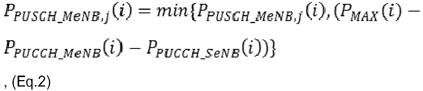

where PPUCCH_MeNB (i), PPUCCH_SeNB (i), PPUSCH_MeNB,j (i), PPUCCH_SeNB,j (i) and PMAX (i) are the power level of the PUCCH of the BS 102 (assumed as the MeNB), the power level of the PUCCH of the BS 104 (assumed as the SeNB), the power level of the PUSCH (including the UL control information) of theBS 102, the power level of the PUSCH (including the UL control information) of theBS 104 and the power level limit, respectively. The index i is the subframe index. The operation of min{A, B} returns the minimum of A and B. As can be seen, the priorities of the power levels described according to theprocess 50 are realized according to the equations (Eq.1), (Eq.2) and (Eq.3). - In addition, for the sum of the power levels to be not greater than the power level limit, the following equations can be used for reducing the power levels with lower priorities:

where wMeNB (i), wSeNB (i), PPUCCH_MeNB,c (i) and PPUSCH_SeNB,c (i) are a weight for theBS 102, a weight for theBS 104, the power level of the PUSCH (without the UL control information) of theBS 102 and the power level of the PUSCH (without the UL control information) of theBS 104, respectively. Thus, according to the above equations, not only the priorities of the power levels are realized but the power level limit is satisfied. As a result, the abovementioned problem of the UL power control for the dual connectivity is solved. -
Fig. 6 is a flowchart of aprocess 60 according to an example of the present invention. Theprocess 60 may be utilized in theUE 100 configured to communicate with theBS 102 and theBS 104, to handle UL power control for theBS 102 and theBS 104. Theprocess 60 may be compiled into theprogram code 214 and includes the following steps: - Step 600: Start.
- Step 602: Determine a first data channel power level of the
BS 102 according to a control channel power level of theBS 102 and a power level limit of theUE 100. - Step 604: Determine a second data channel power level of the
BS 102 according to the first data channel power level of theBS 102, the control channel power level of theBS 102 and the power level limit. - Step 606: End.
- According to the
process 60, a first data channel power level of theBS 102 is determined according to a control channel power level of theBS 102 and a power level limit of theUE 100. Then, a second data channel power level of theBS 102 according to the first data channel power level of theBS 102, the control channel power level of theBS 102 and the power level limit. In other words, the priorities of the power levels from high to low are the control channel power level of theBS 102, the first data channel power level of theBS 102, and the second data channel power level of theBS 102. Preferably, the sum of the power levels is not greater than the power level limit. Thus, the abovementioned problem of the UL power control for the dual connectivity is solved according to theprocess 60. - Realization of the present invention is not limited to the above description.
- In one example, after the
process 60 is performed, a control channel power level of theBS 104 may be determined according to the control channel power level of theBS 102, the first data channel power level of theBS 102, the second data channel power level of theBS 102 and the power level limit. A first data channel power level of theBS 104 may be determined according to the control channel power level of theBS 102, the control channel power level of theBS 104, the first data channel power level of theBS 102, the second data channel power level of theBS 102 and the power level limit. Then, a second data channel power level of theBS 104 may be determined according to the control channel power level of theBS 102, the control channel power level of theBS 104, the first data channel power level of theBS 102, the first data channel power level of theBS 104, the second data channel power level of theBS 102 and the power level limit. In other words, the priorities of the power levels of theBS 102 are not lower than the priorities of theBS 104. - In addition, a first sum of the control channel power level of the
BS 102, the control channel power level of theBS 104, the first data channel power level of theBS 102, the first data channel power level of theBS 104, the second data channel power level of theBS 102 and the second data channel power level of the BS 104 (i.e., the abovementioned power levels) is not greater than the power level limit, for the transmissions to be performed completely. For example, the control channel power level of theBS 104, the first data channel power level of theBS 104, the second data channel power level of theBS 104 and the second data channel power level of theBS 104 may be reduced (e.g., via using various weights) for the first sum to be not greater than the power level limit. That is, the power levels with lower priorities are reduced such that the sum of the power levels is not greater than the power level limit. Further, a first weight may be determined to reduce the control channel power level of theBS 104, the first data channel power level of theBS 104, the second data channel power level of theBS 104 and the second data channel power level of theBS 102, for the first sum to be not greater than the power level limit. - A second sum of the control channel power level of the
BS 104, the first data channel power level of theBS 104 and the second data channel power level of theBS 104 may be determined, when the first sum is not greater than the power level limit. That is, the second sum is a sum of the reduced power levels. Then, the first data channel power level of theBS 104 may be determined according to the control channel power level of theBS 104 and the second sum, and the second data channel power level of theBS 104 may be determined according to the first data channel power level of theBS 104, the control channel power level of theBS 104 and the second sum. Again, a second weight may be determined to reduce the second data channel power level of theBS 104, for a sum of the control channel power level of theBS 104, the first data channel power level of theBS 104 and the second data channel power level of theBS 104 to be not greater than the second sum. - Detail of the control channel power levels and the data channel power levels mentioned above are not limited. For example, the control channel power level may include (or simply be) a power level of a PUCCH. In one example, the first data channel power level may include (or simply be) a power level of a PUSCH comprising UL control information. In one example, the second data channel power level may include at least one power level of at least one PUSCH without UL control information. That is, a priority of the channel with the UL control information is not lower than a priority of the channel without the UL control information.
- In the following example, without loss of generality, the control channel power level, the first data channel power level, the second data channel power level are assumed as the power level of the PUCCH, the power level of the PUSCH including the UL control information and the at least one power level of the at least one PUSCH without the UL control information, respectively. According to the
process 60 and the above description, the power levels can be determined according to the following equations:
where PPUCCH_MeNB (i), PPUSCH_MeNB,j (i) and PMAX (i) are the power level of the PUCCH of the BS 102 (assumed as the MeNB), the power level of the PUSCH (including the UL control information) of theBS 102 and the power level limit, respectively. The index i is the subframe index. The operation of min{A, B} returns the minimum of A and B. As can be seen, the priorities of the power levels described according to theprocess 60 are realized according to the equation (Eq.5). - In addition, for the sum of the power levels to be not greater than the power level limit, the following equations can be used for reducing the power levels with lower priorities:

where wouter (i), PPUCCH_MeNB,c (i), PPUCCH_SeNB (i), PPUSCH_MeNB,j (i) and PPUSCH_SeNB,c (i) are the first weight described previously, the power level of the PUSCH (without the UL control information) of theBS 102, the power level of the PUCCH of the BS 104 (assumed as the SeNB), the power level of the PUSCH (including the UL control information) of theBS 104 and the power level of the PUSCH (without the UL control information) of theBS 104, respectively. - Furthermore, the equations (Eq.5) and (Eq.6) can be seen as an outer scaling process for determining the power levels, and the power level of the PUCCH of the
BS 104, the power level of the PUSCH (including the UL control information) of theBS 104 and the power level of the PUSCH (without the UL control information) of theBS 104 may be further scaled according to an inner scaling process. A nominal maximum power level for theBS 104 is first described as follows:
BS 104. - Then, the power levels of the
BS 104 after performing the inner scaling process can be obtained as follows:

where winner (i) is the second weight described previously. Thus, according to the above equations (i.e., the outer scaling process and/or the inner scaling process), not only the priorities of the power levels are realized but the power level limit is satisfied. As a result, the UL power control for the dual connectivity is solved. - Those skilled in the art should readily make combinations, modifications and/or alterations on the abovementioned description and examples. The abovementioned steps of the processes including suggested steps can be realized by means that could be a hardware, a firmware known as a combination of a hardware device and computer instructions and data that reside as read-only software on the hardware device, or an electronic system. Examples of hardware can include analog, digital and mixed circuits known as microcircuit, microchip, or silicon chip. Examples of the electronic system can include a system on chip (SOC), system in package (SIP), a computer on module (COM), and the
communication device 20.Process 30 and process 40 may be combined together to solve the problems as described above. - To sum up, the present invention provides a method of handling UL power control for dual connectivity. Mechanisms for the UL power control for both synchronous/asynchronous operations are proposed. The mechanisms can be combined as a complete solution for the asynchronous operation. Alternatively, the solutions can be used independently, e.g., combined with other solutions. Thus, the UL power control for the dual connectivity is solved according to the present invention.
- Those skilled in the art will readily observe that numerous modifications and alterations of the device and method may be made while retaining the teachings of the invention. Accordingly, the above disclosure should be construed as limited only by the metes and bounds of the appended claims.
Claims (15)
- A communication device (20) for handling uplink power control configured to communicate with a first base station and a second base station, comprising:a storage unit for storing instructions of:determining a power level of a first uplink (UL) subframe of the first base station and a first power level of a second UL subframe of the second base station according to an initial power level of the first UL subframe and an initial power level of the second UL subframe, wherein a starting boundary of the second UL subframe is within the first UL subframe;performing a first UL transmission with the first base station in the first UL subframe according to the power level of the first UL subframe;determining a second power level of the second UL subframe of the second base station and a first power level of a third UL subframe of the first base station according to the first power level of the second UL subframe and an initial power level of the third UL subframe, wherein a starting boundary of the third UL subframe is within the second UL subframe; andperforming a second UL transmission with the second base station in the second UL subframe according to the second power level of the second UL subframe; anda processing means, coupled to the storage unit, configured to execute the instructions stored in the storage unit.
- The communication device (20) of claim 1, the instructions further comprise:determining a second power level of the third UL subframe and a first power level of a fourth UL subframe of the second base station according to the first power level of the third UL subframe and an initial power level of the fourth UL subframe, wherein a starting boundary of the fourth UL subframe is within the third UL subframe; andperforming a third UL transmission with the first base station in the third UL subframe according to the second power level of the third UL subframe.
- The communication device (20) of claim 1, wherein the first base station is a master base station, and the second base station is a secondary base station.
- The communication device (20) of claim 1, wherein the first UL subframe and the third UL subframe are consecutive UL subframes, and the second UL subframe and the fourth UL subframe are consecutive UL subframes.
- A communication device (20) for handling uplink power control configured to communicate with a first base station and a second base station, comprising:a storage unit for storing instructions of:determining a control channel power level of the second base station according to a control channel power level of the first base station and a power level limit of the communication device(20);determining a first data channel power level of the first base station according to the control channel power level of the first base station, the control channel power level of the second base station and the power level limit; anddetermining a first data channel power level of the second base station according to the control channel power level of the first base station, the control channel power level of the second base station, the first data channel power level of the first base station and the power level limit; anda processing means, coupled to the storage unit, configured to execute the instructions stored in the storage unit.
- The communication device (20) of claim 5, the instructions further comprise:determining a second data channel power level of the first base station according to the control channel power level of the first base station, the control channel power level of the second base station, the first data channel power level of the first base station, the first data channel power level of the second base station and the power level limit; anddetermining a second data channel power level of the second base station according to the control channel power level of the first base station, the control channel power level of the second base station, the first data channel power level of the first base station, the first data channel power level of the second base station, the second data channel power level of the first base station and the power level limit.
- The communication device (20) of claim 6, wherein a sum of the control channel power level of the first base station, the control channel power level of the second base station, the first data channel power level of the first base station, the first data channel power level of the second base station, the second data channel power level of the first base station and the second data channel power level of the second base station is not greater than the power level limit.
- The communication device (20) of claim 7, wherein the second data channel power level of the first base station and the second data channel power level of the second base station are reduced for the sum to be not greater than the power level limit.
- The communication device (20) of claim 8, wherein a first weight and a second weight are determined to reduce the second data channel power level of the first base station and the second data channel power level of the second base station, respectively, for the sum to be not greater than the power level limit.
- A communication device (20) for handling uplink power control configured to communicate with a first base station and a second base station, comprising:a storage unit for storing instructions of:determining a first data channel power level of the first base station according to a control channel power level of the first base station and a power level limit of the communication device (20); anddetermining a second data channel power level of the first base station according to the first data channel power level of the first base station, the control channel power level of the first base station and the power level limit; anda processing means, coupled to the storage unit, configured to execute the instructions stored in the storage unit.
- The communication device (20) of claim 10, the instructions further comprise:determining a control channel power level of the second base station according to the control channel power level of the first base station, the first data channel power level of the first base station, the second data channel power level of the first base station and the power level limit;determining a first data channel power level of the second base station according to the control channel power level of the first base station, the control channel power level of the second base station, the first data channel power level of the first base station, the second data channel power level of the first base station and the power level limit; anddetermining a second data channel power level of the second base station according to the control channel power level of the first base station, the control channel power level of the second base station, the first data channel power level of the first base station, the first data channel power level of the second base station, the second data channel power level of the first base station and the power level limit.
- The communication device (20) of claim 11, wherein a first sum of the control channel power level of the first base station, the control channel power level of the second base station, the first data channel power level of the first base station, the first data channel power level of the second base station, the second data channel power level of the first base station and the second data channel power level of the second base station is not greater than the power level limit.
- The communication device (20) of claim 12, wherein the control channel power level of the second base station, the first data channel power level of the second base station, the second data channel power level of the second base station and the second data channel power level of the first base station are reduced for the first sum to be not greater than the power level limit.
- The communication device (20) of claim 6 or claim 12, wherein the second data channel power level comprises at least one power level of at least one physical uplink (UL) shared channel (PUSCH) without UL control information, the control channel power level comprises a power level of a physical UL control channel (PUCCH), and the first data channel power level comprises a power level of a PUSCH comprising UL control information.
- The communication device (20) of claim 5 or claim 12, wherein the first base station is a master base station, and the second base station is a secondary base station.
Applications Claiming Priority (1)
| Application Number | Priority Date | Filing Date | Title |
|---|---|---|---|
| US201461981214P | 2014-04-18 | 2014-04-18 |
Publications (3)
| Publication Number | Publication Date |
|---|---|
| EP2934048A2 true EP2934048A2 (en) | 2015-10-21 |
| EP2934048A3 EP2934048A3 (en) | 2016-01-06 |
| EP2934048B1 EP2934048B1 (en) | 2017-06-28 |
Family
ID=52946423
Family Applications (1)
| Application Number | Title | Priority Date | Filing Date |
|---|---|---|---|
| EP15163972.1A Active EP2934048B1 (en) | 2014-04-18 | 2015-04-17 | Communication device for handling uplink power control |
Country Status (2)
| Country | Link |
|---|---|
| US (1) | US9398541B2 (en) |
| EP (1) | EP2934048B1 (en) |
Families Citing this family (2)
| Publication number | Priority date | Publication date | Assignee | Title |
|---|---|---|---|---|
| JP2018023040A (en) * | 2016-08-04 | 2018-02-08 | 富士通株式会社 | Base station, radio communication system, and operation method of base station |
| US10582454B2 (en) * | 2017-09-27 | 2020-03-03 | Ofinno, Llc | Power control for uplink control channel |
Family Cites Families (17)
| Publication number | Priority date | Publication date | Assignee | Title |
|---|---|---|---|---|
| TWI496490B (en) * | 2009-03-17 | 2015-08-11 | Interdigital Patent Holdings | Method and apparatus for uplink power control in multiple-input multiple-output |
| KR101701444B1 (en) | 2009-10-02 | 2017-02-03 | 인터디지탈 패튼 홀딩스, 인크 | Method and apparatus for controlling transmit power of transmissions on more than one component carrier |
| US9166719B2 (en) * | 2010-04-28 | 2015-10-20 | Lg Electronics Inc. | Method of transmitting and receiving signals in a mobile communication system using a radio frame including multiple types of subframes and apparatus thereof |
| US8965442B2 (en) | 2010-05-07 | 2015-02-24 | Qualcomm Incorporated | Uplink power control in aggregated carrier communication systems |
| WO2012134581A1 (en) * | 2011-04-01 | 2012-10-04 | Intel Corporation | Flexible configuration of uplink and downlink ratio by exchanging information using an x2 interface |
| US10237833B2 (en) * | 2011-07-28 | 2019-03-19 | Nokia Technologies Oy | Apparatus and method for uplink power control for variable interference conditions |
| CN103765966B (en) | 2011-09-05 | 2018-02-23 | Lg电子株式会社 | Control the terminal device and its method of uplink signal transmission power |
| EP3169119B1 (en) | 2011-09-25 | 2018-02-14 | LG Electronics Inc. | Method and apparatus for controlling uplink transmission power |
| JP5813444B2 (en) * | 2011-09-30 | 2015-11-17 | シャープ株式会社 | Base station, terminal, communication system and communication method |
| WO2013047130A1 (en) * | 2011-09-30 | 2013-04-04 | シャープ株式会社 | Terminal, communication system, base station and communication method |
| US9319990B2 (en) | 2011-10-03 | 2016-04-19 | Qualcomm Incorporated | Method and apparatus for uplink transmission power control and timing in coordinated multipoint transmission schemes |
| JP5990815B2 (en) * | 2011-11-07 | 2016-09-14 | シャープ株式会社 | Base station, terminal, communication system and communication method |
| EP2807881A4 (en) * | 2012-01-29 | 2015-07-08 | Alcatel Lucent | UPLINK OVERLOAD INDICATOR FOR WIRELESS TIME DIVISION DUPLEXING COMMUNICATION SYSTEMS |
| KR20130087965A (en) | 2012-01-30 | 2013-08-07 | 주식회사 팬택 | Method and apparatus for allocating uplink power in multiple timing advance |
| US10206181B2 (en) | 2012-01-30 | 2019-02-12 | Texas Instruments Incorporated | Simultaneous transmission in multiple timing advance groups |
| US9668222B2 (en) * | 2012-06-28 | 2017-05-30 | Telefonaktiebolaget L M Ericsson (Publ) | Method and base station for link adaptation of PDCCH in a radio communication system |
| KR101664876B1 (en) * | 2013-05-14 | 2016-10-12 | 삼성전자 주식회사 | Method and apparatus of interference measurement for inter-cell interference mitigation in tdd wireless communication system |
-
2015
- 2015-04-16 US US14/687,920 patent/US9398541B2/en active Active
- 2015-04-17 EP EP15163972.1A patent/EP2934048B1/en active Active
Non-Patent Citations (1)
| Title |
|---|
| None |
Also Published As
| Publication number | Publication date |
|---|---|
| EP2934048A3 (en) | 2016-01-06 |
| US20150304958A1 (en) | 2015-10-22 |
| US9398541B2 (en) | 2016-07-19 |
| EP2934048B1 (en) | 2017-06-28 |
Similar Documents
| Publication | Publication Date | Title |
|---|---|---|
| CN105515742B (en) | Communication device handling service in unlicensed cell | |
| EP2922366B1 (en) | Method of handling device-to-device operation | |
| US11452091B2 (en) | Device and method of handling hybrid automatic repeat request transmission | |
| US20150296438A1 (en) | Method of Handling Link Failure and Related Communication Device | |
| EP3236704B1 (en) | Device and method of handling device-to-device communication | |
| EP2824861B1 (en) | Method of handling HARQ feedbacks | |
| EP3512298A1 (en) | Method for simultaneous communications with multiple base stations and related communication device | |
| EP2945423A1 (en) | Device for handling measurement configuration for dual connectivity with carrier aggregation | |
| US11871363B2 (en) | Device and method of handling power headroom report for multiple time intervals | |
| US11240842B2 (en) | Device and method of handling transmission/reception for serving cell | |
| US20150098370A1 (en) | Method of Handling HARQ Resource for FDD Carrier and Related Communication Device | |
| US9717013B2 (en) | Device and method of handling measurement configuration | |
| US20160119922A1 (en) | Device and Method of Handling Resource Availability of Unlicensed Band | |
| US9929799B2 (en) | Network and user equipment of HD-FDD communication system for handling HARQ | |
| EP2934048B1 (en) | Communication device for handling uplink power control | |
| US10356724B2 (en) | Device handling power control for time intervals based on power level limit | |
| US9699675B2 (en) | Method of handling interference measurement in TDD system and related communication device | |
| US10149289B2 (en) | Method of handling downlink-only carrier and related communication device |
Legal Events
| Date | Code | Title | Description |
|---|---|---|---|
| PUAI | Public reference made under article 153(3) epc to a published international application that has entered the european phase |
Free format text: ORIGINAL CODE: 0009012 |
|
| 17P | Request for examination filed |
Effective date: 20150417 |
|
| AK | Designated contracting states |
Kind code of ref document: A2 Designated state(s): AL AT BE BG CH CY CZ DE DK EE ES FI FR GB GR HR HU IE IS IT LI LT LU LV MC MK MT NL NO PL PT RO RS SE SI SK SM TR |
|
| AX | Request for extension of the european patent |
Extension state: BA ME |
|
| PUAL | Search report despatched |
Free format text: ORIGINAL CODE: 0009013 |
|
| AK | Designated contracting states |
Kind code of ref document: A3 Designated state(s): AL AT BE BG CH CY CZ DE DK EE ES FI FR GB GR HR HU IE IS IT LI LT LU LV MC MK MT NL NO PL PT RO RS SE SI SK SM TR |
|
| AX | Request for extension of the european patent |
Extension state: BA ME |
|
| RIC1 | Information provided on ipc code assigned before grant |
Ipc: H04W 52/24 20090101ALI20151127BHEP Ipc: H04W 52/36 20090101ALI20151127BHEP Ipc: H04W 52/14 20090101AFI20151127BHEP Ipc: H04W 52/40 20090101ALI20151127BHEP Ipc: H04W 52/16 20090101ALI20151127BHEP Ipc: H04W 52/50 20090101ALI20151127BHEP Ipc: H04W 52/34 20090101ALI20151127BHEP |
|
| RBV | Designated contracting states (corrected) |
Designated state(s): AL AT BE BG CH CY CZ DE DK EE ES FI FR GB GR HR HU IE IS IT LI LT LU LV MC MK MT NL NO PL PT RO RS SE SI SK SM TR |
|
| 17Q | First examination report despatched |
Effective date: 20160908 |
|
| STAA | Information on the status of an ep patent application or granted ep patent |
Free format text: STATUS: EXAMINATION IS IN PROGRESS |
|
| GRAP | Despatch of communication of intention to grant a patent |
Free format text: ORIGINAL CODE: EPIDOSNIGR1 |
|
| STAA | Information on the status of an ep patent application or granted ep patent |
Free format text: STATUS: GRANT OF PATENT IS INTENDED |
|
| INTG | Intention to grant announced |
Effective date: 20170201 |
|
| GRAS | Grant fee paid |
Free format text: ORIGINAL CODE: EPIDOSNIGR3 |
|
| GRAA | (expected) grant |
Free format text: ORIGINAL CODE: 0009210 |
|
| STAA | Information on the status of an ep patent application or granted ep patent |
Free format text: STATUS: THE PATENT HAS BEEN GRANTED |
|
| AK | Designated contracting states |
Kind code of ref document: B1 Designated state(s): AL AT BE BG CH CY CZ DE DK EE ES FI FR GB GR HR HU IE IS IT LI LT LU LV MC MK MT NL NO PL PT RO RS SE SI SK SM TR |
|
| REG | Reference to a national code |
Ref country code: GB Ref legal event code: FG4D |
|
| REG | Reference to a national code |
Ref country code: CH Ref legal event code: EP |
|
| REG | Reference to a national code |
Ref country code: AT Ref legal event code: REF Ref document number: 905835 Country of ref document: AT Kind code of ref document: T Effective date: 20170715 |
|
| REG | Reference to a national code |
Ref country code: IE Ref legal event code: FG4D |
|
| REG | Reference to a national code |
Ref country code: DE Ref legal event code: R096 Ref document number: 602015003281 Country of ref document: DE |
|
| PG25 | Lapsed in a contracting state [announced via postgrant information from national office to epo] |
Ref country code: LT Free format text: LAPSE BECAUSE OF FAILURE TO SUBMIT A TRANSLATION OF THE DESCRIPTION OR TO PAY THE FEE WITHIN THE PRESCRIBED TIME-LIMIT Effective date: 20170628 Ref country code: NO Free format text: LAPSE BECAUSE OF FAILURE TO SUBMIT A TRANSLATION OF THE DESCRIPTION OR TO PAY THE FEE WITHIN THE PRESCRIBED TIME-LIMIT Effective date: 20170928 Ref country code: HR Free format text: LAPSE BECAUSE OF FAILURE TO SUBMIT A TRANSLATION OF THE DESCRIPTION OR TO PAY THE FEE WITHIN THE PRESCRIBED TIME-LIMIT Effective date: 20170628 Ref country code: FI Free format text: LAPSE BECAUSE OF FAILURE TO SUBMIT A TRANSLATION OF THE DESCRIPTION OR TO PAY THE FEE WITHIN THE PRESCRIBED TIME-LIMIT Effective date: 20170628 Ref country code: GR Free format text: LAPSE BECAUSE OF FAILURE TO SUBMIT A TRANSLATION OF THE DESCRIPTION OR TO PAY THE FEE WITHIN THE PRESCRIBED TIME-LIMIT Effective date: 20170929 |
|
| REG | Reference to a national code |
Ref country code: NL Ref legal event code: MP Effective date: 20170628 |
|
| REG | Reference to a national code |
Ref country code: LT Ref legal event code: MG4D |
|
| REG | Reference to a national code |
Ref country code: AT Ref legal event code: MK05 Ref document number: 905835 Country of ref document: AT Kind code of ref document: T Effective date: 20170628 |
|
| PG25 | Lapsed in a contracting state [announced via postgrant information from national office to epo] |
Ref country code: LV Free format text: LAPSE BECAUSE OF FAILURE TO SUBMIT A TRANSLATION OF THE DESCRIPTION OR TO PAY THE FEE WITHIN THE PRESCRIBED TIME-LIMIT Effective date: 20170628 Ref country code: RS Free format text: LAPSE BECAUSE OF FAILURE TO SUBMIT A TRANSLATION OF THE DESCRIPTION OR TO PAY THE FEE WITHIN THE PRESCRIBED TIME-LIMIT Effective date: 20170628 Ref country code: SE Free format text: LAPSE BECAUSE OF FAILURE TO SUBMIT A TRANSLATION OF THE DESCRIPTION OR TO PAY THE FEE WITHIN THE PRESCRIBED TIME-LIMIT Effective date: 20170628 Ref country code: BG Free format text: LAPSE BECAUSE OF FAILURE TO SUBMIT A TRANSLATION OF THE DESCRIPTION OR TO PAY THE FEE WITHIN THE PRESCRIBED TIME-LIMIT Effective date: 20170928 Ref country code: NL Free format text: LAPSE BECAUSE OF FAILURE TO SUBMIT A TRANSLATION OF THE DESCRIPTION OR TO PAY THE FEE WITHIN THE PRESCRIBED TIME-LIMIT Effective date: 20170628 |
|
| PG25 | Lapsed in a contracting state [announced via postgrant information from national office to epo] |
Ref country code: RO Free format text: LAPSE BECAUSE OF FAILURE TO SUBMIT A TRANSLATION OF THE DESCRIPTION OR TO PAY THE FEE WITHIN THE PRESCRIBED TIME-LIMIT Effective date: 20170628 Ref country code: EE Free format text: LAPSE BECAUSE OF FAILURE TO SUBMIT A TRANSLATION OF THE DESCRIPTION OR TO PAY THE FEE WITHIN THE PRESCRIBED TIME-LIMIT Effective date: 20170628 Ref country code: CZ Free format text: LAPSE BECAUSE OF FAILURE TO SUBMIT A TRANSLATION OF THE DESCRIPTION OR TO PAY THE FEE WITHIN THE PRESCRIBED TIME-LIMIT Effective date: 20170628 Ref country code: SK Free format text: LAPSE BECAUSE OF FAILURE TO SUBMIT A TRANSLATION OF THE DESCRIPTION OR TO PAY THE FEE WITHIN THE PRESCRIBED TIME-LIMIT Effective date: 20170628 Ref country code: AT Free format text: LAPSE BECAUSE OF FAILURE TO SUBMIT A TRANSLATION OF THE DESCRIPTION OR TO PAY THE FEE WITHIN THE PRESCRIBED TIME-LIMIT Effective date: 20170628 |
|
| PG25 | Lapsed in a contracting state [announced via postgrant information from national office to epo] |
Ref country code: SM Free format text: LAPSE BECAUSE OF FAILURE TO SUBMIT A TRANSLATION OF THE DESCRIPTION OR TO PAY THE FEE WITHIN THE PRESCRIBED TIME-LIMIT Effective date: 20170628 Ref country code: IS Free format text: LAPSE BECAUSE OF FAILURE TO SUBMIT A TRANSLATION OF THE DESCRIPTION OR TO PAY THE FEE WITHIN THE PRESCRIBED TIME-LIMIT Effective date: 20171028 Ref country code: ES Free format text: LAPSE BECAUSE OF FAILURE TO SUBMIT A TRANSLATION OF THE DESCRIPTION OR TO PAY THE FEE WITHIN THE PRESCRIBED TIME-LIMIT Effective date: 20170628 Ref country code: IT Free format text: LAPSE BECAUSE OF FAILURE TO SUBMIT A TRANSLATION OF THE DESCRIPTION OR TO PAY THE FEE WITHIN THE PRESCRIBED TIME-LIMIT Effective date: 20170628 Ref country code: PL Free format text: LAPSE BECAUSE OF FAILURE TO SUBMIT A TRANSLATION OF THE DESCRIPTION OR TO PAY THE FEE WITHIN THE PRESCRIBED TIME-LIMIT Effective date: 20170628 |
|
| REG | Reference to a national code |
Ref country code: DE Ref legal event code: R097 Ref document number: 602015003281 Country of ref document: DE |
|
| PG25 | Lapsed in a contracting state [announced via postgrant information from national office to epo] |
Ref country code: DK Free format text: LAPSE BECAUSE OF FAILURE TO SUBMIT A TRANSLATION OF THE DESCRIPTION OR TO PAY THE FEE WITHIN THE PRESCRIBED TIME-LIMIT Effective date: 20170628 |
|
| PLBE | No opposition filed within time limit |
Free format text: ORIGINAL CODE: 0009261 |
|
| STAA | Information on the status of an ep patent application or granted ep patent |
Free format text: STATUS: NO OPPOSITION FILED WITHIN TIME LIMIT |
|
| 26N | No opposition filed |
Effective date: 20180329 |
|
| PG25 | Lapsed in a contracting state [announced via postgrant information from national office to epo] |
Ref country code: SI Free format text: LAPSE BECAUSE OF FAILURE TO SUBMIT A TRANSLATION OF THE DESCRIPTION OR TO PAY THE FEE WITHIN THE PRESCRIBED TIME-LIMIT Effective date: 20170628 |
|
| PG25 | Lapsed in a contracting state [announced via postgrant information from national office to epo] |
Ref country code: MC Free format text: LAPSE BECAUSE OF FAILURE TO SUBMIT A TRANSLATION OF THE DESCRIPTION OR TO PAY THE FEE WITHIN THE PRESCRIBED TIME-LIMIT Effective date: 20170628 |
|
| REG | Reference to a national code |
Ref country code: CH Ref legal event code: PL |
|
| REG | Reference to a national code |
Ref country code: BE Ref legal event code: MM Effective date: 20180430 |
|
| REG | Reference to a national code |
Ref country code: IE Ref legal event code: MM4A |
|
| PG25 | Lapsed in a contracting state [announced via postgrant information from national office to epo] |
Ref country code: LU Free format text: LAPSE BECAUSE OF NON-PAYMENT OF DUE FEES Effective date: 20180417 |
|
| PG25 | Lapsed in a contracting state [announced via postgrant information from national office to epo] |
Ref country code: LI Free format text: LAPSE BECAUSE OF NON-PAYMENT OF DUE FEES Effective date: 20180430 Ref country code: CH Free format text: LAPSE BECAUSE OF NON-PAYMENT OF DUE FEES Effective date: 20180430 Ref country code: BE Free format text: LAPSE BECAUSE OF NON-PAYMENT OF DUE FEES Effective date: 20180430 |
|
| PG25 | Lapsed in a contracting state [announced via postgrant information from national office to epo] |
Ref country code: FR Free format text: LAPSE BECAUSE OF NON-PAYMENT OF DUE FEES Effective date: 20180430 Ref country code: IE Free format text: LAPSE BECAUSE OF NON-PAYMENT OF DUE FEES Effective date: 20180417 |
|
| PG25 | Lapsed in a contracting state [announced via postgrant information from national office to epo] |
Ref country code: MT Free format text: LAPSE BECAUSE OF NON-PAYMENT OF DUE FEES Effective date: 20180417 |
|
| PG25 | Lapsed in a contracting state [announced via postgrant information from national office to epo] |
Ref country code: TR Free format text: LAPSE BECAUSE OF FAILURE TO SUBMIT A TRANSLATION OF THE DESCRIPTION OR TO PAY THE FEE WITHIN THE PRESCRIBED TIME-LIMIT Effective date: 20170628 |
|
| PG25 | Lapsed in a contracting state [announced via postgrant information from national office to epo] |
Ref country code: PT Free format text: LAPSE BECAUSE OF FAILURE TO SUBMIT A TRANSLATION OF THE DESCRIPTION OR TO PAY THE FEE WITHIN THE PRESCRIBED TIME-LIMIT Effective date: 20170628 |
|
| PG25 | Lapsed in a contracting state [announced via postgrant information from national office to epo] |
Ref country code: CY Free format text: LAPSE BECAUSE OF FAILURE TO SUBMIT A TRANSLATION OF THE DESCRIPTION OR TO PAY THE FEE WITHIN THE PRESCRIBED TIME-LIMIT Effective date: 20170628 Ref country code: MK Free format text: LAPSE BECAUSE OF NON-PAYMENT OF DUE FEES Effective date: 20170628 Ref country code: HU Free format text: LAPSE BECAUSE OF FAILURE TO SUBMIT A TRANSLATION OF THE DESCRIPTION OR TO PAY THE FEE WITHIN THE PRESCRIBED TIME-LIMIT; INVALID AB INITIO Effective date: 20150417 |
|
| PG25 | Lapsed in a contracting state [announced via postgrant information from national office to epo] |
Ref country code: AL Free format text: LAPSE BECAUSE OF FAILURE TO SUBMIT A TRANSLATION OF THE DESCRIPTION OR TO PAY THE FEE WITHIN THE PRESCRIBED TIME-LIMIT Effective date: 20170628 |
|
| REG | Reference to a national code |
Ref country code: DE Ref legal event code: R082 Ref document number: 602015003281 Country of ref document: DE Representative=s name: WAGNER & GEYER PARTNERSCHAFT MBB PATENT- UND R, DE |
|
| P01 | Opt-out of the competence of the unified patent court (upc) registered |
Effective date: 20230602 |
|
| PGFP | Annual fee paid to national office [announced via postgrant information from national office to epo] |
Ref country code: DE Payment date: 20250305 Year of fee payment: 11 |
|
| PGFP | Annual fee paid to national office [announced via postgrant information from national office to epo] |
Ref country code: GB Payment date: 20260312 Year of fee payment: 12 |