EP2933785A1 - Paper-currency dispensing box - Google Patents
Paper-currency dispensing box Download PDFInfo
- Publication number
- EP2933785A1 EP2933785A1 EP13862084.4A EP13862084A EP2933785A1 EP 2933785 A1 EP2933785 A1 EP 2933785A1 EP 13862084 A EP13862084 A EP 13862084A EP 2933785 A1 EP2933785 A1 EP 2933785A1
- Authority
- EP
- European Patent Office
- Prior art keywords
- banknote
- separating
- wheel
- banknotes
- paper
- Prior art date
- Legal status (The legal status is an assumption and is not a legal conclusion. Google has not performed a legal analysis and makes no representation as to the accuracy of the status listed.)
- Granted
Links
- 238000003825 pressing Methods 0.000 claims abstract description 71
- 230000000670 limiting effect Effects 0.000 claims abstract description 28
- 230000002441 reversible effect Effects 0.000 claims description 9
- 238000007599 discharging Methods 0.000 claims description 8
- 238000005096 rolling process Methods 0.000 claims description 3
- 230000003247 decreasing effect Effects 0.000 claims description 2
- 238000000926 separation method Methods 0.000 abstract description 9
- 230000001154 acute effect Effects 0.000 abstract description 5
- 238000003860 storage Methods 0.000 abstract description 2
- 238000000034 method Methods 0.000 description 9
- 239000013589 supplement Substances 0.000 description 5
- 230000002829 reductive effect Effects 0.000 description 3
- 230000008901 benefit Effects 0.000 description 2
- 238000005520 cutting process Methods 0.000 description 2
- 238000005516 engineering process Methods 0.000 description 2
- 230000008569 process Effects 0.000 description 2
- 230000001502 supplementing effect Effects 0.000 description 2
- 230000007423 decrease Effects 0.000 description 1
- 230000000694 effects Effects 0.000 description 1
- 230000008570 general process Effects 0.000 description 1
- 230000007774 longterm Effects 0.000 description 1
- 239000000463 material Substances 0.000 description 1
- 230000009347 mechanical transmission Effects 0.000 description 1
- 230000036961 partial effect Effects 0.000 description 1
- 230000000717 retained effect Effects 0.000 description 1
Images



Classifications
-
- G—PHYSICS
- G07—CHECKING-DEVICES
- G07D—HANDLING OF COINS OR VALUABLE PAPERS, e.g. TESTING, SORTING BY DENOMINATIONS, COUNTING, DISPENSING, CHANGING OR DEPOSITING
- G07D11/00—Devices accepting coins; Devices accepting, dispensing, sorting or counting valuable papers
- G07D11/10—Mechanical details
- G07D11/12—Containers for valuable papers
- G07D11/13—Containers for valuable papers with internal means for handling valuable papers
-
- B—PERFORMING OPERATIONS; TRANSPORTING
- B65—CONVEYING; PACKING; STORING; HANDLING THIN OR FILAMENTARY MATERIAL
- B65H—HANDLING THIN OR FILAMENTARY MATERIAL, e.g. SHEETS, WEBS, CABLES
- B65H1/00—Supports or magazines for piles from which articles are to be separated
- B65H1/08—Supports or magazines for piles from which articles are to be separated with means for advancing the articles to present the articles to the separating device
- B65H1/12—Supports or magazines for piles from which articles are to be separated with means for advancing the articles to present the articles to the separating device comprising spring
-
- B—PERFORMING OPERATIONS; TRANSPORTING
- B65—CONVEYING; PACKING; STORING; HANDLING THIN OR FILAMENTARY MATERIAL
- B65H—HANDLING THIN OR FILAMENTARY MATERIAL, e.g. SHEETS, WEBS, CABLES
- B65H1/00—Supports or magazines for piles from which articles are to be separated
- B65H1/26—Supports or magazines for piles from which articles are to be separated with auxiliary supports to facilitate introduction or renewal of the pile
- B65H1/266—Support fully or partially removable from the handling machine, e.g. cassette, drawer
-
- B—PERFORMING OPERATIONS; TRANSPORTING
- B65—CONVEYING; PACKING; STORING; HANDLING THIN OR FILAMENTARY MATERIAL
- B65H—HANDLING THIN OR FILAMENTARY MATERIAL, e.g. SHEETS, WEBS, CABLES
- B65H3/00—Separating articles from piles
- B65H3/46—Supplementary devices or measures to assist separation or prevent double feed
- B65H3/52—Friction retainers acting on under or rear side of article being separated
- B65H3/5246—Driven retainers, i.e. the motion thereof being provided by a dedicated drive
-
- B—PERFORMING OPERATIONS; TRANSPORTING
- B65—CONVEYING; PACKING; STORING; HANDLING THIN OR FILAMENTARY MATERIAL
- B65H—HANDLING THIN OR FILAMENTARY MATERIAL, e.g. SHEETS, WEBS, CABLES
- B65H3/00—Separating articles from piles
- B65H3/46—Supplementary devices or measures to assist separation or prevent double feed
- B65H3/56—Elements, e.g. scrapers, fingers, needles, brushes, acting on separated article or on edge of the pile
-
- B—PERFORMING OPERATIONS; TRANSPORTING
- B65—CONVEYING; PACKING; STORING; HANDLING THIN OR FILAMENTARY MATERIAL
- B65H—HANDLING THIN OR FILAMENTARY MATERIAL, e.g. SHEETS, WEBS, CABLES
- B65H2405/00—Parts for holding the handled material
- B65H2405/10—Cassettes, holders, bins, decks, trays, supports or magazines for sheets stacked substantially horizontally
- B65H2405/11—Parts and details thereof
- B65H2405/111—Bottom
-
- B—PERFORMING OPERATIONS; TRANSPORTING
- B65—CONVEYING; PACKING; STORING; HANDLING THIN OR FILAMENTARY MATERIAL
- B65H—HANDLING THIN OR FILAMENTARY MATERIAL, e.g. SHEETS, WEBS, CABLES
- B65H2405/00—Parts for holding the handled material
- B65H2405/10—Cassettes, holders, bins, decks, trays, supports or magazines for sheets stacked substantially horizontally
- B65H2405/11—Parts and details thereof
- B65H2405/113—Front, i.e. portion adjacent to the feeding / delivering side
- B65H2405/1136—Front, i.e. portion adjacent to the feeding / delivering side inclined, i.e. forming an angle different from 90 with the bottom
-
- B—PERFORMING OPERATIONS; TRANSPORTING
- B65—CONVEYING; PACKING; STORING; HANDLING THIN OR FILAMENTARY MATERIAL
- B65H—HANDLING THIN OR FILAMENTARY MATERIAL, e.g. SHEETS, WEBS, CABLES
- B65H2405/00—Parts for holding the handled material
- B65H2405/10—Cassettes, holders, bins, decks, trays, supports or magazines for sheets stacked substantially horizontally
- B65H2405/12—Parts to be handled by user
- B65H2405/121—Locking means
-
- B—PERFORMING OPERATIONS; TRANSPORTING
- B65—CONVEYING; PACKING; STORING; HANDLING THIN OR FILAMENTARY MATERIAL
- B65H—HANDLING THIN OR FILAMENTARY MATERIAL, e.g. SHEETS, WEBS, CABLES
- B65H2405/00—Parts for holding the handled material
- B65H2405/30—Other features of supports for sheets
- B65H2405/31—Supports for sheets fully removable from the handling machine, e.g. cassette
- B65H2405/313—Supports for sheets fully removable from the handling machine, e.g. cassette with integrated handling means, e.g. separating means
-
- B—PERFORMING OPERATIONS; TRANSPORTING
- B65—CONVEYING; PACKING; STORING; HANDLING THIN OR FILAMENTARY MATERIAL
- B65H—HANDLING THIN OR FILAMENTARY MATERIAL, e.g. SHEETS, WEBS, CABLES
- B65H2405/00—Parts for holding the handled material
- B65H2405/30—Other features of supports for sheets
- B65H2405/32—Supports for sheets partially insertable - extractable, e.g. upon sliding movement, drawer
- B65H2405/325—Supports for sheets partially insertable - extractable, e.g. upon sliding movement, drawer with integrated handling means, e.g. separating means
-
- B—PERFORMING OPERATIONS; TRANSPORTING
- B65—CONVEYING; PACKING; STORING; HANDLING THIN OR FILAMENTARY MATERIAL
- B65H—HANDLING THIN OR FILAMENTARY MATERIAL, e.g. SHEETS, WEBS, CABLES
- B65H2601/00—Problem to be solved or advantage achieved
- B65H2601/30—Facilitating or easing
- B65H2601/32—Facilitating or easing entities relating to handling machine
- B65H2601/322—Replenishing
Definitions
- the present application relates to the technique for storing and separating sheet-type medium, and particularly to a banknote dispenser of a financial self-service equipment for storing, separating and dispensing banknotes.
- Self-service equipment is an important equipment for financial institutes, and has a strict management requirement.
- the boundary dimension, usage stability, and safe reliability in management of the operation equipment are important matters to be considered by the providers of the self-service equipments.
- a banknote dispenser for storing, separating and dispensing banknotes is an important module of the financial self-service equipment, and the boundary dimension, operation stability, and safe reliability in operation of the banknote dispenser is related to the user experience of the entire financial self-service equipment.
- the existing banknote dispenser has following features. 1. In a banknote separating mechanism, a banknote separating wheel assembly and a banknote picking wheel assembly are partially coated with rubber. The banknote separating mechanism separates out one sheet of banknote when the banknote separating wheel assembly rotates once, thus the banknote separating wheel assembly rotates continuously to realize continuous banknote separating. 2. A surface of a limiting block placed in front of the banknotes flushes with the stacking direction of a whole stack of banknotes. 3. The banknote dispenser cooperates with parts of the self-service equipment to activate the banknote dischargeable state. 4. A banknote pressing board of the banknote dispenser is tightly fastened via a buckle and can be loosened when the buckle is pressed manually.
- the above banknote dispenser has the following problems. 1.
- the outer diameter of the banknote separating wheel assembly of the banknote separating mechanism is restricted by the length of the banknote in the banknote separating direction.
- the outer perimeter of the banknote separating wheel assembly is required to be greater than the length of the banknote in the banknote separating direction. For example, if the banknotes are separated in the longitudinal direction, and the length of the banknote is 180mm, then the diameter of the banknote separating wheel assembly should be greater or equal to 57mm based on calculation.
- Such banknote dispensing mechanism has a large dimension and can directly cause the banknote dispenser to have a large dimension. 2.
- banknote pressing board It is required to perform a procedure of pressing the buckle manually to loose the banknote pressing board, if the operator misses this procedure, the banknote pressing board will be still in a fastened state, which directly results in an invalid banknote separation and the banknote dispenser being failing to dispense banknotes.
- banknote dispenser has a low operation reliability and a poor fault tolerance.
- a banknote dispenser is provided according to the present application, which has a small dimension and can separate banknotes stably, so as to address the technical issues that the conventional banknote dispenser has an oversized volume and the banknote separation thereof is unstable.
- a banknote dispenser which includes:
- the banknote dispenser also includes a mistake-proof mechanism for a buckle of the banknote pressing board, which includes a buckle configured to retain the banknote pressing board at the lowest position of the base case, and the buckle is movably installed in the housing via a rotating shaft and is provided with a torsion spring configured to allow the buckle to reset automatically.
- a buckle trigger mechanism is arranged on the upper cover at a position corresponding to the buckle.
- the buckle trigger mechanism includes a rib arranged on an inner side wall of the upper cover at a position corresponding to the buckle.
- the banknote dispenser is not allowed to freely discharge banknotes when the banknote dispenser is disengaged from the financial service equipment.
- the banknote separating mechanism further includes a locking mechanism, the locking mechanism includes a gear locking device configured to selectively lock the banknote picking wheel assembly, and a pulling device configured to control the gear locking device to lock and unlock the banknote picking wheel, the gear locking device includes an elongated gear locking sheet, an fastener is provided at an end of the elongated gear locking sheet, and the elongated gear locking sheet is provided with an elongated hole acting as a stroke limiting hole for the elongated gear locking sheet, the guide shaft passes through the stroke limiting hole to movably assemble the elongated gear locking sheet and the banknote separating base plate, and the elongated gear locking sheet is configured to keep the engaging trend between the fastener and the banknote picking mechanism through a gear locking tension spring.
- the pulling device includes a pull arm assembly and a driving assembly
- the pull arm assembly includes an elongated pull arm
- one end of the elongated pull arm is provided with a pull rod in selective contact with the elongated gear locking sheet
- a bearing in rolling contact with the driving assembly is provided at another end of the elongated pull arm via a small shaft.
- the driving assembly includes a lock cylinder relatively fixed to the housing, and a cam configured to rotate together with the lock cylinder, an arc-shaped boss is provided on an outer surface of the cam, the arc-shaped boss has one point with a maximum radius and another point with a minimum radius, and the lock cylinder is configured to drive the cam to rotate, to make the bearing move reciprocally between the point with the maximum radius and the point with the minimum radius of the boss.
- the elongated pull arm is provided with a tension spring, and the tension spring has one end fixed to the elongated pull arm, and another end relatively fixed to the housing.
- an upper cover locking mechanism is arranged on one end of the upper cover where the upper cover engages with or disengages from the base case, and is configured to lock the upper cover and the base case and to maintain the upper cover and the base case as an integral.
- the banknote separating mechanism also includes a banknote conveying wheel and a pinch roller which are assembled in interference fit and configured to deliver out the piece-by-piece separated banknote, and the banknote conveying wheel and the pinch roller are located on one side of the banknote separating wheel assembly where the banknotes are delivered out.
- the banknote dispenser according to the present application has the following advantages.
- the banknote picking wheel assembly and the banknote separating wheel assembly of the banknote separating mechanism adopt a structure with a built-in one-way bearing, and the banknote picking wheel assembly and the banknote separating wheel assembly can both rotate freely in the banknote discharging direction, thereby preventing the rubber wheel from generating a sliding friction force on the banknotes when the banknotes are discharged.
- a full circle rubber structure is used, which allows an inching control of the banknote picking wheel assembly and the banknote separating wheel assembly to send banknotes between the banknote conveying wheel and the pinch roller, and the outer diameter of the banknote separating wheel assembly is not restricted by the length of the banknote and can be designed smaller, thus the space occupied by the banknote separating mechanism is greatly reduced, and the banknote dispenser has a small boundary dimension.
- a guide rib is provided on the surface of the limiting block, to make the stack of banknotes form an acute angle state before the banknotes are separated, which facilitates separating the banknotes, and enables the banknote dispenser to separate banknotes more effectively and stably.
- a locking mechanism is provided to drive a series of mechanical transmission to allow the banknote dispenser to be in a banknote dischargeable state, and the locking mechanism is controlled by the only one matched key, hence the banknote dispenser has a high security.
- a mistake-proof mechanism for the buckle of the banknote pressing board is provided, thus when the upper cover of the banknote dispenser is closed, the buckle is jointly rotated to be disengaged from the banknote pressing board, which avoids the situation that the banknote pressing board is always in the fastened state in the case that the operator misses the procedure of pressing the buckle, hence the banknote dispenser has a high operation reliability and a good fault tolerance.
- a banknote dispenser includes a housing 1, an internal frame 2, a banknote pressing mechanism 3, an upper cover locking mechanism 4, a banknote separating mechanism 5, a limiting block 6, a locking mechanism 7, a mistake-proof mechanism 8 for a buckle of the banknote pressing board, and a necessary power mechanism.
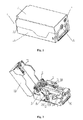
- the housing 1 includes an upper cover 11 and a base case 12, one end of the upper cover 11 is movably connected to one end of the base case 12 via an upper cover rotating shaft 13, and a space for accommodating other components and banknotes is formed when the upper cover 11 is closed on the base case 12.
- the housing 1 is provided with a banknote outlet for discharging the banknotes.
- the upper cover may rotate around the upper cover rotating shaft 13 to open and close the banknote dispenser.
- the internal frame 2 for installing other components is arranged in the housing, and the internal frame 2 is fastened onto an inner surface of a bottom of the base case 12 via bolts.
- the banknote pressing mechanism 3 includes a banknote pressing board 31 placed inside the base case 12 and configured to stack up a stack of banknotes, a guide shaft 32 of the banknote pressing board 31, and a banknote pressing spring 33 which enables the banknote pressing board to always press against a banknote picking wheel assembly of the banknote separating mechanism.
- the guide shaft 32 is limitedly installed on the internal frame 2 via a split washer.
- the banknote pressing board 31 may move upwards along the guide shaft 32 under the action of the banknote pressing spring 33.
- the upper cover locking mechanism 4 is arranged on one end of the upper cover 11 where the upper cover 11 engages with and disengages from the base case 12, and is fixed to the base case 12 via a nut, and is configured to lock and unlock the upper cover 11.
- the banknote separating mechanism 5 is installed in the internal frame 2 near the banknote outlet, and is configured to separate the whole stack of stacked banknotes piece by piece.
- the limiting block 6 is arranged on one end where the stack of banknotes are separated out and is fastened to the internal frame 2 via a bolt.
- the locking device includes a gear locking device 71 and a pulling device 72.
- the gear locking device 71 is arranged on a banknote separating base plate 56 connected to the banknote separating mechanism 5, and the pulling device 72 is fixed to the upper cover 11 via a bolt.
- the mistake-proof mechanism 8 for the buckle of the banknote pressing board is fixed to the internal frame 2 via a bolt.
- FIGS 2 , 4 and 5 are the perspective views showing a banknote separating wheel assembly 51 and a banknote picking wheel assembly 52 of the banknote separating mechanism 5 of the banknote dispenser.
- the banknote separating mechanism is located near the banknote outlet and includes the banknote picking wheel assembly 51 placed on the surface of the banknote, the banknote separating wheel assembly 52 and a reverse wheel 53 which are placed at an end of the banknote and configured to separate the stack of banknotes piece by piece, and a banknote separating base plate 56 configured to install required components.
- the banknote picking wheel assembly 51 includes a banknote picking wheel 511 having a rubber surface, a banknote picking wheel shaft 513 configured to rotate the banknote picking wheel 511, and a first one-way bearing 512 configured to assemble the banknote picking wheel 511 and the banknote picking wheel shaft 513.
- the banknote picking wheel 511 wraps the outer surface of the one-way bearing 512, the banknote picking wheel shaft 513 passes through the center hole of the one-way bearing 512, and the banknote picking wheel 511 is freely rotatable in the banknote discharging direction.
- the banknote separating wheel assembly 52 includes a banknote separating rubber wheel 521 in an interference fit with the reverse wheel 53, a banknote separating wheel shaft 523 configured to rotate the banknote picking rubber wheel, and a second one-way bearing 522 configure to assemble the banknote separating rubber wheel 521 and the banknote separating wheel shaft 523.
- the banknote separating rubber wheel 521 wraps the outer surface of the second one-way bearing 522, the banknote separating wheel shaft 523 passes through the center hole of the second one-way bearing 522, and the banknote separating rubber wheel 521 is freely rotatable in the banknote discharging direction.
- the banknote separating mechanism 5 further includes a banknote conveying wheel 54 and a pinch roller 55 which are assembled in interference fit and configured to deliver out the piece-by-piece separated banknote.
- the banknote conveying wheel 54 and the pinch roller 55 are located on a side of the banknote separating wheel assembly 52 where the banknotes are discharged.
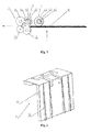
- FIG. 5 The operation principle of the banknote separating mechanism 5 is illustrated in detail.
- each group of wheels rotates in the direction shown by an arrow in the Figure.
- the banknote picking wheel 511 generates a frictional driving force for the uppermost sheet of banknote 07 in the stack of banknotes to enable the banknote 07 to move between the banknote separating wheel assembly 52 and the reverse wheel 53.
- the banknote separating rubber wheel 521 of the banknote separating wheel assembly 52 provides a frictional driving force for the banknote 07, to drive the banknote 07 to continue to move towards the banknote conveying wheel 54 and the pinch roller 55, meanwhile the reverse wheel 53 generates an opposite friction resistance to the banknotes except for the uppermost sheet of banknote, to separate the banknote 07 from other banknotes. Further, the banknote 07 is delivered out of the banknote separating mechanism by the pulling force of the banknote conveying wheel 54 and the pinch roller 55, thus the banknote separating mechanism completes a banknote separation.
- the banknote separating rubber wheel 521 since the banknote separating rubber wheel 521 is installed on the banknote separating wheel shaft 523 via the one-way bearing 522, the banknote separating rubber wheel 521 may rotate freely on the banknote separating wheel shaft 523 in the banknote discharging direction.
- the banknote separating rubber wheel 521 will not generate a sliding frictional resistance to the banknotes 07, in this case, the partial rubber structure in the conventional technology is replaced, that the banknote separating wheel assembly uses a banknote separating wheel hub made of material with a low friction coefficient to reduce the frictional resistance generated when the banknote is pulled out of the banknote separating wheel assembly.
- the banknote conveying wheel 54 and the pinch roller 55 can convey the banknote 07 between the banknote conveying wheel 54 and the pinch roller 55 by performing inching control on the banknote separating wheel assembly 52 and the banknote picking wheel assembly 51, and then the banknote conveying wheel 54 and the pinch roller 55 will generate a pulling force to deliver the banknote 07 out of the banknote separating mechanism 5.
- the inching control of the banknote separating wheel assembly 52 and the banknote picking wheel assembly 51 is performed again, thus the banknote separating mechanism 5 may perform continuous banknote separation by repeating the above process. Therefore, the outer diameter of the banknote separating wheel assembly 52 is not restricted by the length of the banknote and can be designed smaller, and the space occupied by the banknote separating mechanism 5 is greatly reduced and the banknote dispenser has a small boundary dimension.
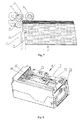
- Figure 6 shows the structure of a limiting block of the banknote dispenser in Figure 3 .
- the limiting block 6 is arranged on one end where the stack of banknotes is separated out and includes a limiting block body 61.
- a surface of a side of the limiting block body 61 near the whole stack of banknotes is provided with four guide ribs 62 arranged in the banknote stacking direction.
- a height of each guide rib 62 progressively decreases in a direction towards the banknote outlet.
- the four guide ribs 62 are uniformly distributed on the limiting block body 61.
- the limiting block 6 is placed between the reverse wheel 53 and the whole stack of banknotes, to align and guide the stack of banknotes.
- the limiting block 6 is designed with a group of guide ribs 62, and there are four guide ribs 62 in two groups in this embodiment.
- the guide ribs 62 extend in the banknote stacking direction and the height of each guide rib 62 is progressively reduced in the banknote stacking direction.
- the acute angle state of the whole stack of banknotes ensures that the first sheet of banknote near the banknote separating mechanism 5 is further forward than the second sheet of banknote so that the first sheet of banknote can be more easily separated out by the frictional driving force of the banknote separating wheel assembly 52, and on the other hand, forms a certain distance between the banknotes in the front back direction in advance by rubbing the banknotes against each other before the stack of banknotes are separated.
- the action of rubbing the banknotes against each other facilitates destroying the adhesion state caused by long-term squeezing between certain kinds of banknotes, especially for a stack of new banknotes, thereby enabling the whole stack of banknotes to be separated and discharged more easily.
- the limiting block 6 makes the whole stack of banknotes form an acute angle state, which facilitates separating the banknotes, before the stack of banknotes are separated, thus the banknote dispenser can realize a more effective and stable banknote separation.
- the banknote dispenser is a carrier of banknotes, thus the security of the management of the banknote dispenser is very important. It is generally required to install the banknote dispenser to related equipment before discharging banknotes; however in some occasions that the banknote dispenser is disengaged from the related equipment, such as in transportation and storage, the banknote dispenser cannot discharge banknotes.
- the banknote dispenser according to the present application is provided with a locking mechanism which is shown in Figure 8.
- Figure 8 is a schematic view showing the internal structure of the banknote dispenser in Figure 1 by partially cutting the upper cover.
- Figure 9 is a schematic view showing the internal structure of the banknote dispenser viewed in the direction A in Figure 8 .
- Figures 10 and 11 are schematic views showing the positions of main components of the locking mechanism 7 when the banknote dispenser is closed.
- the locking mechanism 7 includes a gear locking device 71 configured to selectively lock the banknote picking wheel assembly 51 and a pulling device 72 configured to control the gear locking device 71 to lock and unlock the banknote picking wheel assembly 51.
- the gear locking device 71 is mounted on a banknote separating base plate 56 connected to the banknote picking wheel assembly 51.
- the pulling device 72 is fixed to an inner side of the upper cover 11 via a bolt.
- the gear locking device 71 includes a elongated gear locking sheet 711, and one end of the elongated gear locking sheet 711 is provided with a fastener c.
- the elongated gear locking sheet 711 is provided with an elongated hole acting as a stroke limiting hole, and the guide shaft 712 passes through the stroke limiting hole, thus the elongated gear locking sheet 711 is movably installed on the banknote separating base plate 56.
- the elongated gear locking sheet 711 keeps the engaging trend between the fastener c and the banknote picking mechanism through a gear locking tension spring 713.
- the gear locking sheet 711 includes an extension arm a, a buckling arm b and the fastener c, and is limitedly mounted on the guide shaft 712 by a split washer.
- gear locking tension spring 713 is fastened to the extension arm a of the gear locking sheet 711, and another end of the gear locking tension spring 713 is fastened to a fixed point of the banknote separating base plate 56.
- the pulling device 72 of the locking mechanism is illustrated in conjunction with Figures 11 and 12 .
- the pulling device includes a pull arm assembly 721 and a driving assembly 722.
- the pull arm assembly 721 includes an elongated pull arm 7211, one end of the pull arm 7211 is provided with a pull rod d configured to selectively contact the elongated gear locking sheet 711, and a bearing 7214 configured to be in a rolling contact with the driving assembly is arranged on another end of the pull arm 7211 via a small shaft 7213.
- the elongated pull arm 7211 is provided with a tension spring 7215, and the tension spring 7215 has one end fixed to the elongated pull arm.
- the pull arm assembly 721 is limitedly mounted on a fixing assembly 723 by a split washer, the driving assembly 722 is fastened to the fixing assembly 723 via a nut, and the pull arm assembly 721 is associated with the driving assembly 722.
- Figure 12 is a perspective view showing three major components of the pulling device in Figure 11 .
- the pull arm assembly 721 includes the pull arm 7211, the control pin 7212, the small shaft 7213, the bearing 7214 and the pull arm tension spring 7215.
- the pull arm 7211 includes the pull rod d.
- the control pin 7212 and the small shaft 7213 are fixed to the pull arm 7211 by riveting.
- the bearing 7214 is sleeved on the small shaft 7213.
- One end of the pull arm tension spring 7215 is fastened to the control pin 7212 and another end of the pull arm tension spring 7215 is fastened to a long guide shaft 7232 of the fixing assembly 723.
- the driving assembly 722 includes a security lock 7221 and a cam 7222.
- the security lock 7221 can only be driven by the only one matched key.
- the cam 7222 is tightly fixed to the security lock 7221 by a bolt, and is designed with a boss structure. The boss has a lowest point e and a highest point f.
- the cam 7222 may rotate in the direction as shown by an arrow in the figure to switch the boss between the lowest point e and the highest point f.
- the fixing assembly 723 includes a fixing frame 7231, the long guide shaft 7232 and a short guide shaft 7233.
- the long guide shaft 7232 and the short guide shaft 7233 are fastened to the fixing frame 7231 by riveting.
- Figure 13a and Figure 13b are two-dimensional schematic views showing a closed state of the locking device of the banknote dispenser in Figure 11 .
- the driving mechanism 722 when the driving mechanism 722 is in a closed state, the cam 7222 associated with the bearing 7214 of the pull arm assembly 721 is at the lowest point e of the boss, and at this moment, the pull arm assembly 721 is in a free state, and the pull arm 7211 moves in the direction as shown by an arrow s in the figures under the action of the pulling force of the pull arm tension spring 7215 and stops moving until the bearing 7214 comes into contact with the boss of the cam 7222.
- the gear locking device 71 is also in a free state, the gear locking sheet 711 moves in the direction shown by an arrow t in the figures under the action of the pulling force of the gear locking tension spring 713, and at this moment, the fastener c of the gear locking sheet 711 is inserted into a gear structure 5111 on one side of the banknote picking wheel 5111.
- the gear structure 5111 is a part of the banknote picking wheel 511, and the gear structure 5111 and the banknote picking wheel 511 cannot move with respect to each other. Due to the interference of the fastener c of the gear locking sheet 711, the banknote picking wheel 511 cannot rotate, and the banknote separating mechanism cannot separate banknotes, thus the banknote dispenser cannot discharge banknotes.
- Figure 14a and Figure 14b are two-dimensional schematic views showing an open state of the locking device of the banknote dispenser in Figure 11 .
- the driving mechanism 722 rotates from the closed state to an open state
- the cam 7222 associated with the bearing 7214 of the pull arm assembly 721 is switched from the lowest point e to the highest point f of the boss.
- the bearing 7214 of the pull arm assembly 721 is subjected to a guiding force of the boss of the cam 7222, which makes the pull arm 7211 overcome the pulling force of the pull arm tension spring 7215 to move in the direction shown by an arrow u in the figures.
- the pull rod d of the pull arm 7211 applies a pulling force on the buckling arm b of the gear locking sheet 711, which makes the gear locking device 711 overcome the pulling force of the gear locking tension spring 713 to move in the direction shown by an arrow v in the figures, thereby disengaging the fastener c of the gear locking sheet 711 from the gear structure 5111 of the banknote picking wheel 511.
- the banknote picking wheel 511 is rotatable and the banknote separating mechanism can perform banknote separation, thereby allowing the banknote dispenser to be in a dischargeable state.
- the banknote dispenser according to the present application has a locking mechanism, and the opening and closing of the locking mechanism 7 is realized by rotating the driving device 722.
- the rotating of the driving device 722 is controlled by the only one matched key, that is, whether the banknote dispenser according to the present application can discharge banknotes is only controlled by the person who has the only access to the key, in this way, the security of management of the banknote dispenser is greatly improved.
- Banknote supplement is a general process in the daily operation of the banknote dispenser.
- the banknote dispenser dispenses out all banknotes and is empty, the operator needs to supply the banknote dispenser with banknotes to ensure the banknote dispenser to operate normally.
- the banknote pressing board needs to be pushed back to a certain position to free up a space for receiving the banknotes.
- a buckle is provided inside the banknotes dispenser. The buckle is used to fasten the banknote pressing board, to enable the banknote pressing board to overcome the force of the spring to stay at the certain position.
- the banknote pressing board can restore to a normal operation state and apply a pushing force to the banknotes under the action of the spring force, to press the banknotes against the banknote separating mechanism. It should be noted that, if the banknote pressing board is in the fastened state, the banknote pressing board cannot provide a pushing force to the banknotes, and the banknotes cannot be pressed against the banknote separating mechanism, which directly causes the banknote separating mechanism to be unable to separate banknotes, and causes the banknote dispenser to fail to discharge banknotes.
- banknote pressing board It is required to solve the problem, that a procedure of pressing the buckle manually is required to loose the banknote pressing board, and if the operator misses this procedure, the banknote pressing board will be still in the fastened state and can not operate normally, which directly results in an invalid banknote separation of the banknote separating mechanism and the banknote dispenser being failing to dispense banknotes.
- banknote dispenser has a low operation reliability and a poor fault tolerance.
- the banknote dispenser includes a mistake-proof mechanism for the buckle of the banknote pressing board.
- Figure 15 is a perspective view showing the mistake-proof mechanism 8 for the buckle of the banknote pressing board of the banknote dispenser in Figure 2 .
- the mistake-proof mechanism 8 for the buckle of the banknote pressing board includes a buckle 81 configured to retain the banknote pressing board at the lowest position of the base case.
- the buckle 81 is movably installed in the housing via a rotating shaft 82 and is provided with a torsion spring 83 configured to reset the buckle 81 automatically.
- a buckle trigger mechanism is arranged on the upper cover at a position corresponding to the buckle 81, and accordingly, a retaining triangular portion L corresponding to the buckle is arranged on the banknote pressing board.
- the buckle trigger mechanism is embodied as a rib k that is arranged on the inner side wall of the upper cover 11 at a position corresponding to the buckle 81.
- the buckle 81 includes a large slide surface g configured to allow the rib k to slide thereon, a small slide surface h configured to allow the banknote pressing board to slide thereon, and a hook i for retaining the banknote pressing board.
- the buckle 81 and the torsion spring 83 are sleeved on the rotating shaft 82, and the buckle 81 is rotatable around the rotating shaft 82.
- FIG. 16 is a schematic view showing the state of the banknote pressing board 31 before being fastened.
- the operator pushes the banknote pressing board 31 in the direction shown by an arrow n in the figures before supplementing banknotes.
- the banknote pressing board 31 overcomes the spring force of the banknote pressing spring 33 to move in the direction shown by the arrow n.
- the triangular portion L of the banknote pressing board 31 comes into contact with the small slide surface h of the buckle 81 and drives the buckle 81 to rotate around the rotating shaft 82 in the direction shown by an arrow o in the figures.
- the banknote pressing board 31 continues to move in the direction shown by the arrow n in the figures until the triangular portion L is disengaged from the small slide surface h of the buckle 81.
- the buckle 81 rotates in the direction shown by an arrow p in the figures by the torsion of the torsion spring 83 and the hook i of the buckle 81 is retained by the triangular portion L of the banknote pressing board 31, thereby fastening the banknote pressing board.
- the operator closes the upper cover 11 of the housing after banknotes supplement is completed.
- the rib k of the upper cover 11 rotates in the direction shown by an arrow q in the figure along with the closing of the upper cover 11, and comes into contact with the large slide surface g of the buckle 81 and drives the buckle 81 to rotate around the rotating shaft 82 in the direction shown by an arrow r in the figure.
- the hook i of the buckle 81 is already disengaged from the triangular portion L of the banknote pressing board 31 when the upper cover 11 is closed in place.
- the banknote pressing board 31 moves in the direction shown by an arrow m in the figure by the spring force of the banknote pressing spring 33, and is restored to a normal operation state to generate a pushing force on the banknotes.
- the operator only needs to close the upper cover 11 of the housing, and when the upper cover 11 is closed, the buckle 81 is rotated to be disengaged from the banknote pressing board 31, thus the banknote pressing board 31 is loosened and restored to the normal operation state, thereby avoiding the problem that the banknote pressing board is always in the fastened state and fails to operate normally in the case that the operator misses the procedure of pressing the buckle.
- the banknote dispenser according to the present application has a high operation reliability and a good fault tolerance.
Landscapes
- Engineering & Computer Science (AREA)
- Mechanical Engineering (AREA)
- Physics & Mathematics (AREA)
- General Physics & Mathematics (AREA)
- Sheets, Magazines, And Separation Thereof (AREA)
- Pile Receivers (AREA)
Abstract
Description
- This application claims the benefit of priority to Chinese Patent Application No.
201210532429.6 - The present application relates to the technique for storing and separating sheet-type medium, and particularly to a banknote dispenser of a financial self-service equipment for storing, separating and dispensing banknotes.
- Self-service equipment is an important equipment for financial institutes, and has a strict management requirement. The boundary dimension, usage stability, and safe reliability in management of the operation equipment are important matters to be considered by the providers of the self-service equipments. A banknote dispenser for storing, separating and dispensing banknotes is an important module of the financial self-service equipment, and the boundary dimension, operation stability, and safe reliability in operation of the banknote dispenser is related to the user experience of the entire financial self-service equipment.
- The existing banknote dispenser has following features. 1. In a banknote separating mechanism, a banknote separating wheel assembly and a banknote picking wheel assembly are partially coated with rubber. The banknote separating mechanism separates out one sheet of banknote when the banknote separating wheel assembly rotates once, thus the banknote separating wheel assembly rotates continuously to realize continuous banknote separating. 2. A surface of a limiting block placed in front of the banknotes flushes with the stacking direction of a whole stack of banknotes. 3. The banknote dispenser cooperates with parts of the self-service equipment to activate the banknote dischargeable state. 4. A banknote pressing board of the banknote dispenser is tightly fastened via a buckle and can be loosened when the buckle is pressed manually.
- The above banknote dispenser has the following problems. 1. The outer diameter of the banknote separating wheel assembly of the banknote separating mechanism is restricted by the length of the banknote in the banknote separating direction. The outer perimeter of the banknote separating wheel assembly is required to be greater than the length of the banknote in the banknote separating direction. For example, if the banknotes are separated in the longitudinal direction, and the length of the banknote is 180mm, then the diameter of the banknote separating wheel assembly should be greater or equal to 57mm based on calculation. Such banknote dispensing mechanism has a large dimension and can directly cause the banknote dispenser to have a large dimension. 2. The ends, to be separated, of the whole stack of stored banknotes are aligned, which causes a poor stability in the piece-by-piece banknote separating process for the banknote dispenser. 3. When the banknote dispenser has not been assembled to the equipment, the cooperation between the banknote dispenser and the parts of the equipment can be simulated with simple tools, to allow the banknote dispenser to be in the banknote dischargeable state, which may result in banknotes in the banknote dispenser being stolen, therefore the banknote dispenser has a low security. 4. It is required to perform a procedure of pressing the buckle manually to loose the banknote pressing board, if the operator misses this procedure, the banknote pressing board will be still in a fastened state, which directly results in an invalid banknote separation and the banknote dispenser being failing to dispense banknotes. Such banknote dispenser has a low operation reliability and a poor fault tolerance.
- A banknote dispenser is provided according to the present application, which has a small dimension and can separate banknotes stably, so as to address the technical issues that the conventional banknote dispenser has an oversized volume and the banknote separation thereof is unstable.
- For realizing the above objects, a banknote dispenser is provided according to the present application, which includes:
- a housing, including an upper cover and a base case, one end of the upper cover being movably connected to one end of the base case via a rotating shaft, and a space for accommodating other components and banknotes being formed in the case that the upper cover is closed on the base case, and the housing being provided with a banknote outlet for discharging the banknotes;
- a banknote separating mechanism located near the banknote outlet, and including a banknote picking wheel assembly configured to be placed on a surface of the banknotes, a banknote separating wheel assembly and a reverse wheel which are configured to be placed at an end of the banknotes and to separate a stack of banknotes piece by piece, and a banknote separating base plate configured to install required components, wherein the banknote picking wheel assembly includes a banknote picking wheel having a rubber surface, a banknote picking wheel shaft configured to rotate the banknote picking wheel, and a first one-way bearing configured to assemble the banknote picking wheel and the banknote picking wheel shaft, and the banknote separating wheel assembly includes a banknote separating rubber wheel in an interference fit with the reverse wheel, a banknote separating wheel shaft configured to rotate the banknote separating rubber wheel, and a second one-way bearing configured to assemble the banknote separating rubber wheel and the banknote separating wheel shaft;
- a banknote pressing mechanism, including a banknote pressing board placed in the base case and configured to stack up the stack of banknotes, a guide shaft of the banknote pressing board, and a spring configured to enable the banknote pressing board to always press against the banknote picking wheel assembly of the banknote separating mechanism; and
- a limiting block, arranged on one end where the stack of banknotes is separated out, at least a guide rib being provided on a surface of the limiting block in a banknote stacking direction, and a height of the guide rib being decreased progressively in the direction towards the banknote outlet.
- For solving the problem that the banknote pressing board is required to be manually unlocked when the banknote dispenser is used, preferably, the banknote dispenser also includes a mistake-proof mechanism for a buckle of the banknote pressing board, which includes a buckle configured to retain the banknote pressing board at the lowest position of the base case, and the buckle is movably installed in the housing via a rotating shaft and is provided with a torsion spring configured to allow the buckle to reset automatically.
- Furthermore, a buckle trigger mechanism is arranged on the upper cover at a position corresponding to the buckle.
- Furthermore, the buckle trigger mechanism includes a rib arranged on an inner side wall of the upper cover at a position corresponding to the buckle.
- For ensuring the security of the banknotes in the banknote dispenser, the banknote dispenser is not allowed to freely discharge banknotes when the banknote dispenser is disengaged from the financial service equipment. Preferably, the banknote separating mechanism further includes a locking mechanism, the locking mechanism includes a gear locking device configured to selectively lock the banknote picking wheel assembly, and a pulling device configured to control the gear locking device to lock and unlock the banknote picking wheel, the gear locking device includes an elongated gear locking sheet, an fastener is provided at an end of the elongated gear locking sheet, and the elongated gear locking sheet is provided with an elongated hole acting as a stroke limiting hole for the elongated gear locking sheet, the guide shaft passes through the stroke limiting hole to movably assemble the elongated gear locking sheet and the banknote separating base plate, and the elongated gear locking sheet is configured to keep the engaging trend between the fastener and the banknote picking mechanism through a gear locking tension spring.
- Preferably, the pulling device includes a pull arm assembly and a driving assembly, the pull arm assembly includes an elongated pull arm, one end of the elongated pull arm is provided with a pull rod in selective contact with the elongated gear locking sheet, and a bearing in rolling contact with the driving assembly is provided at another end of the elongated pull arm via a small shaft.
- Preferably, the driving assembly includes a lock cylinder relatively fixed to the housing, and a cam configured to rotate together with the lock cylinder, an arc-shaped boss is provided on an outer surface of the cam, the arc-shaped boss has one point with a maximum radius and another point with a minimum radius, and the lock cylinder is configured to drive the cam to rotate, to make the bearing move reciprocally between the point with the maximum radius and the point with the minimum radius of the boss.
- Preferably, the elongated pull arm is provided with a tension spring, and the tension spring has one end fixed to the elongated pull arm, and another end relatively fixed to the housing.
- To prevent the upper cover from being illegally opened, preferably, an upper cover locking mechanism is arranged on one end of the upper cover where the upper cover engages with or disengages from the base case, and is configured to lock the upper cover and the base case and to maintain the upper cover and the base case as an integral.
- To ensure that the piece-by-piece separated banknote is smoothly discharged out of the housing, preferably, the banknote separating mechanism also includes a banknote conveying wheel and a pinch roller which are assembled in interference fit and configured to deliver out the piece-by-piece separated banknote, and the banknote conveying wheel and the pinch roller are located on one side of the banknote separating wheel assembly where the banknotes are delivered out.
- Compared with the conventional technology, the banknote dispenser according to the present application has the following advantages.
- 1. The banknote picking wheel assembly and the banknote separating wheel assembly of the banknote separating mechanism adopt a structure with a built-in one-way bearing, and the banknote picking wheel assembly and the banknote separating wheel assembly can both rotate freely in the banknote discharging direction, thereby preventing the rubber wheel from generating a sliding friction force on the banknotes when the banknotes are discharged. A full circle rubber structure is used, which allows an inching control of the banknote picking wheel assembly and the banknote separating wheel assembly to send banknotes between the banknote conveying wheel and the pinch roller, and the outer diameter of the banknote separating wheel assembly is not restricted by the length of the banknote and can be designed smaller, thus the space occupied by the banknote separating mechanism is greatly reduced, and the banknote dispenser has a small boundary dimension.
- 2. A guide rib is provided on the surface of the limiting block, to make the stack of banknotes form an acute angle state before the banknotes are separated, which facilitates separating the banknotes, and enables the banknote dispenser to separate banknotes more effectively and stably.
- 3. A locking mechanism is provided to drive a series of mechanical transmission to allow the banknote dispenser to be in a banknote dischargeable state, and the locking mechanism is controlled by the only one matched key, hence the banknote dispenser has a high security.
- 4. A mistake-proof mechanism for the buckle of the banknote pressing board is provided, thus when the upper cover of the banknote dispenser is closed, the buckle is jointly rotated to be disengaged from the banknote pressing board, which avoids the situation that the banknote pressing board is always in the fastened state in the case that the operator misses the procedure of pressing the buckle, hence the banknote dispenser has a high operation reliability and a good fault tolerance.
- The present application is further described in conjunction with drawings and embodiments.
-
Figure 1 is an overall schematic view of a banknote dispenser according to the present application; -
Figure 2 is an overall schematic view of the banknote dispenser inFigure 1 with an upper cover being opened; -
Figure 3 is an overall schematic view of the banknote dispenser inFigure 1 with the upper cover and a banknote separating base plate being opened at the same time; -
Figure 4 is a perspective view showing a banknote separating wheel assembly and a banknote picking wheel assembly of a banknote separating mechanism of the banknote dispenser inFigure 2 ; -
Figure 5 is a schematic view showing the working principle of the banknote separating mechanism of the banknote dispenser inFigure 2 ; -
Figure 6 is a schematic view showing the structure of a limiting block of the banknote dispenser inFigure 3 ; -
Figure 7 is a schematic view showing the working state of the limiting block of the banknote dispenser inFigure 3 ; -
Figure 8 is a schematic view showing the internal structure of the banknote dispenser inFigure 1 by partially cutting the upper cover; -
Figure 9 is a schematic view showing the internal structure of the banknote dispenser viewed in the direction A inFigure 8 ; -
Figure 10 is a perspective view showing a gear locking device of a locking mechanism of the banknote dispenser inFigure 9 ; -
Figure 11 is a perspective view showing a pulling device of the locking mechanism of the banknote dispenser inFigure 9 ; -
Figure 12 is a perspective view showing three components of the pulling device of the locking mechanism of the banknote dispenser inFigure 11 ; -
Figure 13a is a two-dimensional front view showing a closed state of the locking device of the banknote dispenser inFigure 9 ; -
Figure 13b is a two-dimensional top view showing the closed state of the locking device of the banknote dispenser inFigure 9 ; -
Figure 14a is a two-dimensional front view showing an open state of the locking device of the banknote dispenser inFigure 9 ; -
Figure 14b is a two-dimensional top view showing the open state of the locking device of the banknote dispenser inFigure 9 ; -
Figure 15 is a perspective view showing a mistake-proof mechanism for a buckle of a banknote pressing board of the banknote dispenser inFigure 2 ; -
Figure 16 is a schematic view showing an open state of the banknote dispenser before the banknote pressing board is fastened; -
Figure 17 is a schematic view showing the open state of the banknote dispenser when the banknote pressing board is fastened; and -
Figure 18 is a schematic view showing the closed state of the banknote dispenser when the banknote pressing board is unfastened. - Technical solutions of embodiments of the present application are described clearly and completely in conjunction with drawings hereinafter.
- Reference is made to
Figures 1, 2 and3 . A banknote dispenser according to the present application includes a housing 1, aninternal frame 2, a banknote pressing mechanism 3, an uppercover locking mechanism 4, abanknote separating mechanism 5, a limitingblock 6, alocking mechanism 7, a mistake-proof mechanism 8 for a buckle of the banknote pressing board, and a necessary power mechanism. As shown inFigure 1 , the housing 1 includes anupper cover 11 and abase case 12, one end of theupper cover 11 is movably connected to one end of thebase case 12 via an uppercover rotating shaft 13, and a space for accommodating other components and banknotes is formed when theupper cover 11 is closed on thebase case 12. The housing 1 is provided with a banknote outlet for discharging the banknotes. The upper cover may rotate around the uppercover rotating shaft 13 to open and close the banknote dispenser. As shown inFigures 2 and3 , to facilitate arranging internal components in the housing, theinternal frame 2 for installing other components is arranged in the housing, and theinternal frame 2 is fastened onto an inner surface of a bottom of thebase case 12 via bolts. As shown inFigure 2 , the banknote pressing mechanism 3 includes abanknote pressing board 31 placed inside thebase case 12 and configured to stack up a stack of banknotes, aguide shaft 32 of thebanknote pressing board 31, and abanknote pressing spring 33 which enables the banknote pressing board to always press against a banknote picking wheel assembly of the banknote separating mechanism. Theguide shaft 32 is limitedly installed on theinternal frame 2 via a split washer. Thebanknote pressing board 31 may move upwards along theguide shaft 32 under the action of thebanknote pressing spring 33. The uppercover locking mechanism 4 is arranged on one end of theupper cover 11 where theupper cover 11 engages with and disengages from thebase case 12, and is fixed to thebase case 12 via a nut, and is configured to lock and unlock theupper cover 11. Thebanknote separating mechanism 5 is installed in theinternal frame 2 near the banknote outlet, and is configured to separate the whole stack of stacked banknotes piece by piece. As shown inFigure 3 , the limitingblock 6 is arranged on one end where the stack of banknotes are separated out and is fastened to theinternal frame 2 via a bolt. As shown inFigure 2 , the locking device includes agear locking device 71 and a pullingdevice 72. Thegear locking device 71 is arranged on a banknoteseparating base plate 56 connected to thebanknote separating mechanism 5, and the pullingdevice 72 is fixed to theupper cover 11 via a bolt. As shown inFigure 2 , the mistake-proof mechanism 8 for the buckle of the banknote pressing board is fixed to theinternal frame 2 via a bolt. - Reference is made to
Figures 2 ,4 and5 , which are the perspective views showing a banknoteseparating wheel assembly 51 and a banknotepicking wheel assembly 52 of thebanknote separating mechanism 5 of the banknote dispenser. The banknote separating mechanism is located near the banknote outlet and includes the banknotepicking wheel assembly 51 placed on the surface of the banknote, the banknoteseparating wheel assembly 52 and areverse wheel 53 which are placed at an end of the banknote and configured to separate the stack of banknotes piece by piece, and a banknoteseparating base plate 56 configured to install required components. The banknotepicking wheel assembly 51 includes abanknote picking wheel 511 having a rubber surface, a banknotepicking wheel shaft 513 configured to rotate thebanknote picking wheel 511, and a first one-way bearing 512 configured to assemble thebanknote picking wheel 511 and the banknotepicking wheel shaft 513. Thebanknote picking wheel 511 wraps the outer surface of the one-way bearing 512, the banknotepicking wheel shaft 513 passes through the center hole of the one-way bearing 512, and thebanknote picking wheel 511 is freely rotatable in the banknote discharging direction. The banknoteseparating wheel assembly 52 includes a banknote separatingrubber wheel 521 in an interference fit with thereverse wheel 53, a banknoteseparating wheel shaft 523 configured to rotate the banknote picking rubber wheel, and a second one-way bearing 522 configure to assemble the banknote separatingrubber wheel 521 and the banknoteseparating wheel shaft 523. The banknote separatingrubber wheel 521 wraps the outer surface of the second one-way bearing 522, the banknoteseparating wheel shaft 523 passes through the center hole of the second one-way bearing 522, and the banknote separatingrubber wheel 521 is freely rotatable in the banknote discharging direction. In addition, to ensure that the piece-by-piece separated banknote can be smoothly delivered out of the housing 1, preferably, thebanknote separating mechanism 5 further includes abanknote conveying wheel 54 and apinch roller 55 which are assembled in interference fit and configured to deliver out the piece-by-piece separated banknote. Thebanknote conveying wheel 54 and thepinch roller 55 are located on a side of the banknoteseparating wheel assembly 52 where the banknotes are discharged. - Reference is made to
Figure 5 . The operation principle of thebanknote separating mechanism 5 is illustrated in detail. When thebanknote separating mechanism 5 starts to work, each group of wheels rotates in the direction shown by an arrow in the Figure. Firstly, thebanknote picking wheel 511 generates a frictional driving force for the uppermost sheet ofbanknote 07 in the stack of banknotes to enable thebanknote 07 to move between the banknoteseparating wheel assembly 52 and thereverse wheel 53. Further, the banknote separatingrubber wheel 521 of the banknoteseparating wheel assembly 52 provides a frictional driving force for thebanknote 07, to drive thebanknote 07 to continue to move towards thebanknote conveying wheel 54 and thepinch roller 55, meanwhile thereverse wheel 53 generates an opposite friction resistance to the banknotes except for the uppermost sheet of banknote, to separate thebanknote 07 from other banknotes. Further, thebanknote 07 is delivered out of the banknote separating mechanism by the pulling force of thebanknote conveying wheel 54 and thepinch roller 55, thus the banknote separating mechanism completes a banknote separation. It is to be noted that, since the banknote separatingrubber wheel 521 is installed on the banknoteseparating wheel shaft 523 via the one-way bearing 522, the banknote separatingrubber wheel 521 may rotate freely on the banknoteseparating wheel shaft 523 in the banknote discharging direction. Therefore, when the banknote is between thebanknote conveying wheel 54 and thepinch roller 55 and is delivered out by the pulling force of thebanknote conveying wheel 54 and thepinch roller 55, the banknote separatingrubber wheel 521 will not generate a sliding frictional resistance to thebanknotes 07, in this case, the partial rubber structure in the conventional technology is replaced, that the banknote separating wheel assembly uses a banknote separating wheel hub made of material with a low friction coefficient to reduce the frictional resistance generated when the banknote is pulled out of the banknote separating wheel assembly. Besides, with the above structure, it can convey thebanknote 07 between thebanknote conveying wheel 54 and thepinch roller 55 by performing inching control on the banknoteseparating wheel assembly 52 and the banknotepicking wheel assembly 51, and then thebanknote conveying wheel 54 and thepinch roller 55 will generate a pulling force to deliver thebanknote 07 out of thebanknote separating mechanism 5. After thebanknote 07 is delivered out, the inching control of the banknoteseparating wheel assembly 52 and the banknotepicking wheel assembly 51 is performed again, thus thebanknote separating mechanism 5 may perform continuous banknote separation by repeating the above process. Therefore, the outer diameter of the banknoteseparating wheel assembly 52 is not restricted by the length of the banknote and can be designed smaller, and the space occupied by thebanknote separating mechanism 5 is greatly reduced and the banknote dispenser has a small boundary dimension. -
Figure 6 shows the structure of a limiting block of the banknote dispenser inFigure 3 . The limitingblock 6 is arranged on one end where the stack of banknotes is separated out and includes a limitingblock body 61. A surface of a side of the limitingblock body 61 near the whole stack of banknotes is provided with fourguide ribs 62 arranged in the banknote stacking direction. A height of eachguide rib 62 progressively decreases in a direction towards the banknote outlet. The fourguide ribs 62 are uniformly distributed on the limitingblock body 61. - The operation state and effect of the limiting
block 6 is illustrated in detail in conjunction withFigure 7 hereinafter. As shown inFigure 7 , the limitingblock 6 is placed between thereverse wheel 53 and the whole stack of banknotes, to align and guide the stack of banknotes. The limitingblock 6 is designed with a group ofguide ribs 62, and there are fourguide ribs 62 in two groups in this embodiment. Theguide ribs 62 extend in the banknote stacking direction and the height of eachguide rib 62 is progressively reduced in the banknote stacking direction. With the above structure, the whole stack of banknotes previously with flush ends form an acute angle state due to the limiting of theguide ribs 62. The acute angle state of the whole stack of banknotes, on one hand, ensures that the first sheet of banknote near thebanknote separating mechanism 5 is further forward than the second sheet of banknote so that the first sheet of banknote can be more easily separated out by the frictional driving force of the banknoteseparating wheel assembly 52, and on the other hand, forms a certain distance between the banknotes in the front back direction in advance by rubbing the banknotes against each other before the stack of banknotes are separated. The action of rubbing the banknotes against each other facilitates destroying the adhesion state caused by long-term squeezing between certain kinds of banknotes, especially for a stack of new banknotes, thereby enabling the whole stack of banknotes to be separated and discharged more easily. Hence, the limitingblock 6 makes the whole stack of banknotes form an acute angle state, which facilitates separating the banknotes, before the stack of banknotes are separated, thus the banknote dispenser can realize a more effective and stable banknote separation. - The banknote dispenser is a carrier of banknotes, thus the security of the management of the banknote dispenser is very important. It is generally required to install the banknote dispenser to related equipment before discharging banknotes; however in some occasions that the banknote dispenser is disengaged from the related equipment, such as in transportation and storage, the banknote dispenser cannot discharge banknotes. For meeting the above requirements, the banknote dispenser according to the present application is provided with a locking mechanism which is shown in
Figure 8. Figure 8 is a schematic view showing the internal structure of the banknote dispenser inFigure 1 by partially cutting the upper cover.Figure 9 is a schematic view showing the internal structure of the banknote dispenser viewed in the direction A inFigure 8 .Figures 10 and11 are schematic views showing the positions of main components of thelocking mechanism 7 when the banknote dispenser is closed. Thelocking mechanism 7 includes agear locking device 71 configured to selectively lock the banknotepicking wheel assembly 51 and a pullingdevice 72 configured to control thegear locking device 71 to lock and unlock the banknotepicking wheel assembly 51. Thegear locking device 71 is mounted on a banknoteseparating base plate 56 connected to the banknotepicking wheel assembly 51. The pullingdevice 72 is fixed to an inner side of theupper cover 11 via a bolt. As shown inFigure 10 , thegear locking device 71 includes a elongatedgear locking sheet 711, and one end of the elongatedgear locking sheet 711 is provided with a fastener c. The elongatedgear locking sheet 711 is provided with an elongated hole acting as a stroke limiting hole, and theguide shaft 712 passes through the stroke limiting hole, thus the elongatedgear locking sheet 711 is movably installed on the banknote separatingbase plate 56. The elongatedgear locking sheet 711 keeps the engaging trend between the fastener c and the banknote picking mechanism through a gear lockingtension spring 713. Specifically, thegear locking sheet 711 includes an extension arm a, a buckling arm b and the fastener c, and is limitedly mounted on theguide shaft 712 by a split washer. One end of the gear lockingtension spring 713 is fastened to the extension arm a of thegear locking sheet 711, and another end of the gear lockingtension spring 713 is fastened to a fixed point of the banknote separatingbase plate 56. When thegear locking device 71 is in a free state, thegear locking sheet 711 moves in the direction shown by an arrow in the figure by the pulling force of the gear lockingtension spring 713. - The pulling
device 72 of the locking mechanism is illustrated in conjunction withFigures 11 and 12 . The pulling device includes apull arm assembly 721 and a drivingassembly 722. Thepull arm assembly 721 includes anelongated pull arm 7211, one end of thepull arm 7211 is provided with a pull rod d configured to selectively contact the elongatedgear locking sheet 711, and abearing 7214 configured to be in a rolling contact with the driving assembly is arranged on another end of thepull arm 7211 via asmall shaft 7213. Preferably, theelongated pull arm 7211 is provided with atension spring 7215, and thetension spring 7215 has one end fixed to the elongated pull arm. In this embodiment, one end of the tension spring is fixed by acontrol pin 7212, and another end of the tension spring is relatively fixed to the housing 1. Thepull arm assembly 721 is limitedly mounted on a fixingassembly 723 by a split washer, the drivingassembly 722 is fastened to the fixingassembly 723 via a nut, and thepull arm assembly 721 is associated with the drivingassembly 722.Figure 12 is a perspective view showing three major components of the pulling device inFigure 11 . Thepull arm assembly 721 includes thepull arm 7211, thecontrol pin 7212, thesmall shaft 7213, thebearing 7214 and the pullarm tension spring 7215. Thepull arm 7211 includes the pull rod d. Thecontrol pin 7212 and thesmall shaft 7213 are fixed to thepull arm 7211 by riveting. Thebearing 7214 is sleeved on thesmall shaft 7213. One end of the pullarm tension spring 7215 is fastened to thecontrol pin 7212 and another end of the pullarm tension spring 7215 is fastened to along guide shaft 7232 of the fixingassembly 723. When thepull arm assembly 721 is in a free state, thepull arm 7211 moves in the direction shown by an arrow in the figure by the force of the pullarm tension spring 7215. The drivingassembly 722 includes asecurity lock 7221 and acam 7222. Thesecurity lock 7221 can only be driven by the only one matched key. Thecam 7222 is tightly fixed to thesecurity lock 7221 by a bolt, and is designed with a boss structure. The boss has a lowest point e and a highest point f. Thecam 7222 may rotate in the direction as shown by an arrow in the figure to switch the boss between the lowest point e and the highest point f. The fixingassembly 723 includes afixing frame 7231, thelong guide shaft 7232 and ashort guide shaft 7233. Thelong guide shaft 7232 and theshort guide shaft 7233 are fastened to thefixing frame 7231 by riveting. -
Figure 13a andFigure 13b are two-dimensional schematic views showing a closed state of the locking device of the banknote dispenser inFigure 11 . With the above structure, when thedriving mechanism 722 is in a closed state, thecam 7222 associated with thebearing 7214 of thepull arm assembly 721 is at the lowest point e of the boss, and at this moment, thepull arm assembly 721 is in a free state, and thepull arm 7211 moves in the direction as shown by an arrow s in the figures under the action of the pulling force of the pullarm tension spring 7215 and stops moving until thebearing 7214 comes into contact with the boss of thecam 7222. Meanwhile, thegear locking device 71 is also in a free state, thegear locking sheet 711 moves in the direction shown by an arrow t in the figures under the action of the pulling force of the gear lockingtension spring 713, and at this moment, the fastener c of thegear locking sheet 711 is inserted into agear structure 5111 on one side of thebanknote picking wheel 5111. It should be noted that, thegear structure 5111 is a part of thebanknote picking wheel 511, and thegear structure 5111 and thebanknote picking wheel 511 cannot move with respect to each other. Due to the interference of the fastener c of thegear locking sheet 711, thebanknote picking wheel 511 cannot rotate, and the banknote separating mechanism cannot separate banknotes, thus the banknote dispenser cannot discharge banknotes. -
Figure 14a and Figure 14b are two-dimensional schematic views showing an open state of the locking device of the banknote dispenser inFigure 11 . When thedriving mechanism 722 rotates from the closed state to an open state, thecam 7222 associated with thebearing 7214 of thepull arm assembly 721 is switched from the lowest point e to the highest point f of the boss. At this moment, thebearing 7214 of thepull arm assembly 721 is subjected to a guiding force of the boss of thecam 7222, which makes thepull arm 7211 overcome the pulling force of the pullarm tension spring 7215 to move in the direction shown by an arrow u in the figures. Further, the pull rod d of thepull arm 7211 applies a pulling force on the buckling arm b of thegear locking sheet 711, which makes thegear locking device 711 overcome the pulling force of the gear lockingtension spring 713 to move in the direction shown by an arrow v in the figures, thereby disengaging the fastener c of thegear locking sheet 711 from thegear structure 5111 of thebanknote picking wheel 511. At this moment, thebanknote picking wheel 511 is rotatable and the banknote separating mechanism can perform banknote separation, thereby allowing the banknote dispenser to be in a dischargeable state. - The banknote dispenser according to the present application has a locking mechanism, and the opening and closing of the
locking mechanism 7 is realized by rotating thedriving device 722. However, the rotating of thedriving device 722 is controlled by the only one matched key, that is, whether the banknote dispenser according to the present application can discharge banknotes is only controlled by the person who has the only access to the key, in this way, the security of management of the banknote dispenser is greatly improved. - Banknote supplement is a general process in the daily operation of the banknote dispenser. When the banknote dispenser dispenses out all banknotes and is empty, the operator needs to supply the banknote dispenser with banknotes to ensure the banknote dispenser to operate normally. When supplementing the banknotes, the banknote pressing board needs to be pushed back to a certain position to free up a space for receiving the banknotes. In order to keep the banknote pressing board at that position to make it easy for the operator to supplement banknotes, a buckle is provided inside the banknotes dispenser. The buckle is used to fasten the banknote pressing board, to enable the banknote pressing board to overcome the force of the spring to stay at the certain position. When the banknotes supplement is completed, the operator needs to press the buckle to disengage it from the banknote pressing board, then the banknote pressing board can restore to a normal operation state and apply a pushing force to the banknotes under the action of the spring force, to press the banknotes against the banknote separating mechanism. It should be noted that, if the banknote pressing board is in the fastened state, the banknote pressing board cannot provide a pushing force to the banknotes, and the banknotes cannot be pressed against the banknote separating mechanism, which directly causes the banknote separating mechanism to be unable to separate banknotes, and causes the banknote dispenser to fail to discharge banknotes. It is required to solve the problem, that a procedure of pressing the buckle manually is required to loose the banknote pressing board, and if the operator misses this procedure, the banknote pressing board will be still in the fastened state and can not operate normally, which directly results in an invalid banknote separation of the banknote separating mechanism and the banknote dispenser being failing to dispense banknotes. Such banknote dispenser has a low operation reliability and a poor fault tolerance.
- For solving the above problem, the banknote dispenser according to the present application includes a mistake-proof mechanism for the buckle of the banknote pressing board.
Figure 15 is a perspective view showing the mistake-proof mechanism 8 for the buckle of the banknote pressing board of the banknote dispenser inFigure 2 . The mistake-proof mechanism 8 for the buckle of the banknote pressing board includes abuckle 81 configured to retain the banknote pressing board at the lowest position of the base case. Thebuckle 81 is movably installed in the housing via a rotatingshaft 82 and is provided with atorsion spring 83 configured to reset thebuckle 81 automatically. Correspondingly, a buckle trigger mechanism is arranged on the upper cover at a position corresponding to thebuckle 81, and accordingly, a retaining triangular portion L corresponding to the buckle is arranged on the banknote pressing board. The buckle trigger mechanism is embodied as a rib k that is arranged on the inner side wall of theupper cover 11 at a position corresponding to thebuckle 81. Specifically, thebuckle 81 includes a large slide surface g configured to allow the rib k to slide thereon, a small slide surface h configured to allow the banknote pressing board to slide thereon, and a hook i for retaining the banknote pressing board. Thebuckle 81 and thetorsion spring 83 are sleeved on therotating shaft 82, and thebuckle 81 is rotatable around the rotatingshaft 82. - The operation principle of the mistake-proof mechanism for the buckle of the banknote pressing banknote is further illustrated herein in conjunction with
Figures 16 to 18 . Reference is made toFigure 16 , which is a schematic view showing the state of thebanknote pressing board 31 before being fastened. The operator pushes thebanknote pressing board 31 in the direction shown by an arrow n in the figures before supplementing banknotes. Thebanknote pressing board 31 overcomes the spring force of thebanknote pressing spring 33 to move in the direction shown by the arrow n. The triangular portion L of thebanknote pressing board 31 comes into contact with the small slide surface h of thebuckle 81 and drives thebuckle 81 to rotate around the rotatingshaft 82 in the direction shown by an arrow o in the figures. - Furthermore, as shown in
Figure 17 , thebanknote pressing board 31 continues to move in the direction shown by the arrow n in the figures until the triangular portion L is disengaged from the small slide surface h of thebuckle 81. Thebuckle 81 rotates in the direction shown by an arrow p in the figures by the torsion of thetorsion spring 83 and the hook i of thebuckle 81 is retained by the triangular portion L of thebanknote pressing board 31, thereby fastening the banknote pressing board. - Furthermore, as shown in
Figure 18 , the operator closes theupper cover 11 of the housing after banknotes supplement is completed. The rib k of theupper cover 11 rotates in the direction shown by an arrow q in the figure along with the closing of theupper cover 11, and comes into contact with the large slide surface g of thebuckle 81 and drives thebuckle 81 to rotate around the rotatingshaft 82 in the direction shown by an arrow r in the figure. The hook i of thebuckle 81 is already disengaged from the triangular portion L of thebanknote pressing board 31 when theupper cover 11 is closed in place. Then, thebanknote pressing board 31 moves in the direction shown by an arrow m in the figure by the spring force of thebanknote pressing spring 33, and is restored to a normal operation state to generate a pushing force on the banknotes. With the above structure, after the banknote supplement is completed, the operator only needs to close theupper cover 11 of the housing, and when theupper cover 11 is closed, thebuckle 81 is rotated to be disengaged from thebanknote pressing board 31, thus thebanknote pressing board 31 is loosened and restored to the normal operation state, thereby avoiding the problem that the banknote pressing board is always in the fastened state and fails to operate normally in the case that the operator misses the procedure of pressing the buckle. The banknote dispenser according to the present application has a high operation reliability and a good fault tolerance. - The embodiments described hereinabove are only specific implementations of the present application, and the scope of the present application is not limited to this. It is obvious for the person skilled in the art to make a few of changes and replacements based on the technical scope disclosed by the present application, and these changes and replacements are also deemed to fall into the scope of the present application. Therefore, the scope of the present application is defined by the claims.
Claims (10)
- A banknote dispenser, comprising:a housing, comprising an upper cover and a base case, one end of the upper cover being movably connected to one end of the base case via a rotating shaft, and a space for accommodating other components and banknotes being formed in the case that the upper cover is closed on the base case, and the housing being provided with a banknote outlet for discharging the banknotes;a banknote separating mechanism located near the banknote outlet, and comprising a banknote picking wheel assembly configured to be placed on a surface of the banknotes, a banknote separating wheel assembly and a reverse wheel which are configured to be placed at an end of the banknotes and to separate a stack of banknotes piece by piece, and a banknote separating base plate configured to install required components, wherein the banknote picking wheel assembly comprises a banknote picking wheel having a rubber surface, a banknote picking wheel shaft configured to rotate the banknote picking wheel, and a first one-way bearing configured to assemble the banknote picking wheel and the banknote picking wheel shaft, and the banknote separating wheel assembly comprises a banknote separating rubber wheel in an interference fit with the reverse wheel, a banknote separating wheel shaft configured to rotate the banknote separating rubber wheel, and a second one-way bearing configured to assemble the banknote separating rubber wheel and the banknote separating wheel shaft;a banknote pressing mechanism, comprising a banknote pressing board placed in the base case and configured to stack up the stack of banknotes, a guide shaft of the banknote pressing board, and a banknote pressing spring configured to enable the banknote pressing board to always press against the banknote picking wheel assembly of the banknote separating mechanism; anda limiting block, arranged on one end where the stack of banknotes is separated out, at least a guide rib being provided on a surface of the limiting block in a banknote stacking direction, and a height of the guide rib being decreased progressively in the direction towards the banknote outlet.
- The banknote dispenser according to claim 1, further comprising a mistake-proof mechanism for a buckle of the banknote pressing board, which comprises a buckle configured to retain the banknote pressing board at the lowest position of the base case, and the buckle is movably installed in the housing via a rotating shaft and is provided with a torsion spring configured to allow the buckle to reset automatically.
- The banknote dispenser according to claim 2, wherein a buckle trigger mechanism is arranged on the upper cover at a position corresponding to the buckle.
- The banknote dispenser according to claim 3, wherein the buckle trigger mechanism comprises a rib arranged on an inner side wall of the upper cover at a position corresponding to the buckle.
- The banknote dispenser according to claim 1, wherein the banknote separating mechanism further comprises a locking mechanism, the locking mechanism comprises a gear locking device configured to selectively lock the banknote picking wheel assembly, and a pulling device configured to control the gear locking device to lock and unlock the banknote picking wheel, the gear locking device comprises an elongated gear locking sheet, an fastener is provided at an end of the elongated gear locking sheet, and the elongated gear locking sheet is provided with an elongated hole acting as a stroke limiting hole for the elongated gear locking sheet, the guide shaft passes through the stroke limiting hole to movably assemble the elongated gear locking sheet and the banknote separating base plate, and the elongated gear locking sheet is configured to keep the engaging trend between the fastener and the banknote picking mechanism through a gear locking tension spring.
- The banknote dispenser according to claim 5, wherein the pulling device comprises a pull arm assembly and a driving assembly, the pull arm assembly comprises an elongated pull arm, one end of the elongated pull arm is provided with a pull rod in selective contact with the elongated gear locking sheet, and a bearing in rolling contact with the driving assembly is provided at another end of the elongated pull arm via a small shaft.
- The banknote dispenser according to claim 6, wherein the driving assembly comprises a lock cylinder relatively fixed to the housing, and a cam configured to rotate together with the lock cylinder, an arc-shaped boss is provided on an outer surface of the cam, the arc-shaped boss has one point with a maximum radius and another point with a minimum radius, and the lock cylinder is configured to drive the cam to rotate, to make the bearing move reciprocally between the point with the maximum radius and the point with the minimum radius of the boss.
- The banknote dispenser according to claim 6, wherein the elongated pull arm is provided with a tension spring, and the tension spring has one end fixed to the elongated pull arm, and another end relatively fixed to the housing.
- The banknote dispenser according to claim 1, wherein an upper cover locking mechanism is arranged on one end of the upper cover where the upper cover engages with or disengages from the base case, and is configured to lock the upper cover and the base case and to maintain the upper cover and the base case as an integral.
- The banknote dispenser according to claim 1, wherein the banknote separating mechanism further comprises a banknote conveying wheel and a pinch roller which are assembled in interference fit and configured to deliver out the piece-by-piece separated banknote, and the banknote conveying wheel and the pinch roller are located on one side of the banknote separating wheel assembly where the banknotes are delivered out.
Applications Claiming Priority (2)
| Application Number | Priority Date | Filing Date | Title |
|---|---|---|---|
| CN201210532429.6A CN103035062B (en) | 2012-12-11 | 2012-12-11 | Money emitting box |
| PCT/CN2013/078627 WO2014089962A1 (en) | 2012-12-11 | 2013-07-02 | Paper-currency dispensing box |
Publications (3)
| Publication Number | Publication Date |
|---|---|
| EP2933785A1 true EP2933785A1 (en) | 2015-10-21 |
| EP2933785A4 EP2933785A4 (en) | 2016-01-13 |
| EP2933785B1 EP2933785B1 (en) | 2017-12-27 |
Family
ID=48021926
Family Applications (1)
| Application Number | Title | Priority Date | Filing Date |
|---|---|---|---|
| EP13862084.4A Not-in-force EP2933785B1 (en) | 2012-12-11 | 2013-07-02 | Paper-currency dispensing box |
Country Status (8)
| Country | Link |
|---|---|
| US (1) | US9299207B2 (en) |
| EP (1) | EP2933785B1 (en) |
| CN (1) | CN103035062B (en) |
| AU (1) | AU2013359714B2 (en) |
| CL (1) | CL2015001455A1 (en) |
| IN (1) | IN2015DN04149A (en) |
| WO (1) | WO2014089962A1 (en) |
| ZA (1) | ZA201503516B (en) |
Families Citing this family (20)
| Publication number | Priority date | Publication date | Assignee | Title |
|---|---|---|---|---|
| CN103035062B (en) * | 2012-12-11 | 2015-01-14 | 广州广电运通金融电子股份有限公司 | Money emitting box |
| CN103646465A (en) * | 2013-12-24 | 2014-03-19 | 广州广电运通金融电子股份有限公司 | Banknote collection and separation device and financial self-service equipment |
| CN103985192B (en) | 2014-05-30 | 2016-04-20 | 广州广电运通金融电子股份有限公司 | Circulation all-in-one machine and note distribution device thereof |
| CN104123785A (en) * | 2014-07-18 | 2014-10-29 | 广州广电运通金融电子股份有限公司 | Sheet medium storing device |
| CN104355042B (en) * | 2014-11-07 | 2016-03-23 | 南京熊猫电子股份有限公司 | A kind of open transfer passage fool-proof mechanism |
| CN104484940B (en) * | 2014-12-19 | 2017-05-24 | 广州广电运通金融电子股份有限公司 | Paper money dispensing case capable of preventing secondary unlocking |
| CN105809816B (en) * | 2014-12-30 | 2018-05-04 | 聚龙股份有限公司 | A kind of storage and note input mechanism for ATM type of financial equipment |
| CN106384460A (en) * | 2016-10-14 | 2017-02-08 | 深圳怡化电脑股份有限公司 | Cash recycling system |
| CN106952388A (en) * | 2017-02-16 | 2017-07-14 | 上海古鳌电子科技股份有限公司 | A kind of paper money discrimination frame and the paper currency detection magnetic devices with paper money discrimination frame |
| CN108694786B (en) * | 2017-04-07 | 2020-07-24 | 山东新北洋信息技术股份有限公司 | Bank note box and cash recycling machine |
| CN107016780B (en) * | 2017-05-27 | 2023-04-07 | 深圳怡化电脑股份有限公司 | Riding wheel structure for pressing paper money by self weight and related device |
| USD847253S1 (en) * | 2017-08-24 | 2019-04-30 | International Currency Technologies Corporation | Bill acceptor |
| CN108053549B (en) * | 2018-02-02 | 2024-02-06 | 深圳怡化电脑股份有限公司 | Passenger receiving device and financial self-service terminal |
| CN108734854B (en) * | 2018-07-19 | 2024-04-16 | 长城信息股份有限公司 | Mobile ticket box with separating function |
| CN109147158B (en) * | 2018-11-07 | 2024-02-06 | 苏州日宝科技有限责任公司 | Paper money deposit machine |
| CN110766856B (en) * | 2019-10-10 | 2025-05-16 | 维融科技股份有限公司 | A banknote feeding module and banknote adding machine |
| US12344989B2 (en) * | 2022-03-04 | 2025-07-01 | Haier Us Appliance Solutions, Inc. | Dryer appliance with a sheet dispenser |
| JP7547421B2 (en) * | 2022-08-29 | 2024-09-09 | 日本金銭機械株式会社 | Storage |
| CN116935527B (en) * | 2023-08-21 | 2026-04-10 | 广州运通智能科技股份有限公司 | Cash drawers and self-service financial equipment |
| CN121708683A (en) * | 2024-09-19 | 2026-03-20 | 威海新北洋荣鑫科技股份有限公司 | Cash boxes and cash recycling equipment |
Family Cites Families (31)
| Publication number | Priority date | Publication date | Assignee | Title |
|---|---|---|---|---|
| FI781640A7 (en) | 1977-06-10 | 1978-12-11 | Joensas Inter Marketing | ARKSEPARERINGS- OCH MATNINGSANORDNING |
| JPS5751643A (en) * | 1980-09-11 | 1982-03-26 | Laurel Bank Mach Co Ltd | Paper money accumulating apparatus |
| GB8516969D0 (en) * | 1985-07-04 | 1985-08-07 | De La Rue Syst | Sheet presenting assembly |
| JPH07215518A (en) * | 1994-02-07 | 1995-08-15 | Fuji Electric Co Ltd | Paper separation / delivery device |
| GB2400365B (en) * | 2003-03-24 | 2006-06-28 | Int Currency Tech | Banknote dispenser |
| US7856401B2 (en) * | 2003-07-11 | 2010-12-21 | Ncr Corporation | Self-service terminal |
| KR100608442B1 (en) * | 2005-03-02 | 2006-08-02 | 노틸러스효성 주식회사 | Feeder Stacking Device |
| KR101343679B1 (en) * | 2005-09-12 | 2013-12-20 | 노틸러스효성 주식회사 | Separating apparatus of paper money and the method thereof, the method of receipt and drawing of money |
| EP2223874B1 (en) * | 2005-12-19 | 2013-12-04 | MEI, Inc. | Dispensing unit for notes of value |
| US20080007146A1 (en) * | 2006-05-18 | 2008-01-10 | De La Rue International Limited | Cash dispenser |
| KR200440186Y1 (en) | 2006-08-24 | 2008-05-28 | 인터내셔날 커런시 테크놀로지 코포레이션 | Banknote identifier lock control device |
| KR100802288B1 (en) | 2006-12-29 | 2008-02-11 | 노틸러스효성 주식회사 | Banknote Machine |
| JP5094143B2 (en) | 2007-01-31 | 2012-12-12 | 日立オムロンターミナルソリューションズ株式会社 | Paper sheet feeding device and paper sheet stacking device |
| WO2008138368A1 (en) * | 2007-05-11 | 2008-11-20 | Talaris Cash Dispensing Systems Ab | Document stacking module |
| CN100578537C (en) * | 2007-08-10 | 2010-01-06 | 杨友靠 | Longitudinal paper money intake bill counter |
| JP5141577B2 (en) * | 2009-01-27 | 2013-02-13 | 沖電気工業株式会社 | Paper sheet separation and accumulation mechanism |
| US20110036680A1 (en) * | 2009-08-12 | 2011-02-17 | International Currency Technologies Corporation | Bill box |
| US8322721B2 (en) * | 2009-10-30 | 2012-12-04 | Ncr Corporation | Media dispenser |
| JP5617343B2 (en) * | 2010-05-20 | 2014-11-05 | 沖電気工業株式会社 | Medium stacking and feeding device |
| KR20120041465A (en) * | 2010-10-21 | 2012-05-02 | 노틸러스효성 주식회사 | Structire of snap fit for preventing separation of assembly from the snap fit |
| US8430395B2 (en) * | 2010-11-16 | 2013-04-30 | Ncr Corporation | Pick unit |
| US8496242B2 (en) | 2010-11-29 | 2013-07-30 | Ncr Corporation | Media cassette |
| CN102737438A (en) * | 2011-04-15 | 2012-10-17 | 上海灵岳电子设备有限公司 | Banknote counting machine |
| CN202563587U (en) * | 2011-10-23 | 2012-11-28 | 浙江方泰电器有限公司 | Friction bill sorting device |
| CN102496206B (en) * | 2011-12-16 | 2014-07-02 | 广州广电运通金融电子股份有限公司 | Clearing and binding all-in-one machine and bill stacking and sorting module thereof |
| CN203025837U (en) | 2012-12-11 | 2013-06-26 | 广州广电运通金融电子股份有限公司 | Cash dispensing box with fool-proof function through cash pressing plate fastener |
| CN203025838U (en) | 2012-12-11 | 2013-06-26 | 广州广电运通金融电子股份有限公司 | Paper money discharge box with lock |
| CN203025836U (en) | 2012-12-11 | 2013-06-26 | 广州广电运通金融电子股份有限公司 | Paper money outlet box with paper money position limitation |
| CN103035062B (en) | 2012-12-11 | 2015-01-14 | 广州广电运通金融电子股份有限公司 | Money emitting box |
| CN203025839U (en) | 2012-12-11 | 2013-06-26 | 广州广电运通金融电子股份有限公司 | Small cash dispensing box |
| US8844806B2 (en) * | 2012-12-19 | 2014-09-30 | Ncr Corporation | Selective bunch presentation |
-
2012
- 2012-12-11 CN CN201210532429.6A patent/CN103035062B/en not_active Expired - Fee Related
-
2013
- 2013-07-02 WO PCT/CN2013/078627 patent/WO2014089962A1/en not_active Ceased
- 2013-07-02 AU AU2013359714A patent/AU2013359714B2/en not_active Ceased
- 2013-07-02 US US14/442,059 patent/US9299207B2/en active Active
- 2013-07-02 IN IN4149DEN2015 patent/IN2015DN04149A/en unknown
- 2013-07-02 EP EP13862084.4A patent/EP2933785B1/en not_active Not-in-force
-
2015
- 2015-05-19 ZA ZA2015/03516A patent/ZA201503516B/en unknown
- 2015-05-28 CL CL2015001455A patent/CL2015001455A1/en unknown
Also Published As
| Publication number | Publication date |
|---|---|
| EP2933785B1 (en) | 2017-12-27 |
| CL2015001455A1 (en) | 2015-08-14 |
| EP2933785A4 (en) | 2016-01-13 |
| WO2014089962A1 (en) | 2014-06-19 |
| ZA201503516B (en) | 2016-09-28 |
| IN2015DN04149A (en) | 2015-10-16 |
| US20150302680A1 (en) | 2015-10-22 |
| AU2013359714B2 (en) | 2016-03-17 |
| US9299207B2 (en) | 2016-03-29 |
| CN103035062B (en) | 2015-01-14 |
| CN103035062A (en) | 2013-04-10 |
| AU2013359714A1 (en) | 2015-05-21 |
Similar Documents
| Publication | Publication Date | Title |
|---|---|---|
| AU2013359714B2 (en) | Paper-currency dispensing box | |
| CN203025839U (en) | Small cash dispensing box | |
| US20160176665A1 (en) | Cassette for storing sheet media | |
| CN203025838U (en) | Paper money discharge box with lock | |
| US11253110B1 (en) | Dispenser for soap and sanitizer | |
| CA2848645C (en) | Folded sheet dispenser with overfill prevention device | |
| CN102124500B (en) | Bank note case with roll storage | |
| US7963519B2 (en) | Media pick system and method | |
| EP1249413B1 (en) | Automatic teller machine | |
| CN203025836U (en) | Paper money outlet box with paper money position limitation | |
| US11963642B2 (en) | Dispenser insert for dispensing sheet products | |
| CN203025837U (en) | Cash dispensing box with fool-proof function through cash pressing plate fastener | |
| CN104484940B (en) | Paper money dispensing case capable of preventing secondary unlocking | |
| US6991392B2 (en) | Door assembly having a print media delivery system | |
| KR101970512B1 (en) | Portable printer | |
| CN113768399A (en) | roll paper box | |
| CN106184039A (en) | The governor motion of boot-lid panel aperture and ratchet thereof | |
| CN217185874U (en) | Roll paper box | |
| CN211180957U (en) | Supplementary paper money device that folds | |
| EP2916023A1 (en) | A resilient pawl for a dispenser mechanism, a dispenser mechanism and a dispenser | |
| JP2006178710A (en) | Passbook payout mechanism | |
| EP4001191B1 (en) | A banknote stack transport arrangement, corresponding cash handling machine, and method for transporting one or more banknotes | |
| KR100642242B1 (en) | Banknote discharging device with banknote theft prevention function | |
| JP4465632B2 (en) | Card body dispensing device |
Legal Events
| Date | Code | Title | Description |
|---|---|---|---|
| PUAI | Public reference made under article 153(3) epc to a published international application that has entered the european phase |
Free format text: ORIGINAL CODE: 0009012 |
|
| 17P | Request for examination filed |
Effective date: 20150429 |
|
| AK | Designated contracting states |
Kind code of ref document: A1 Designated state(s): AL AT BE BG CH CY CZ DE DK EE ES FI FR GB GR HR HU IE IS IT LI LT LU LV MC MK MT NL NO PL PT RO RS SE SI SK SM TR |
|
| AX | Request for extension of the european patent |
Extension state: BA ME |
|
| A4 | Supplementary search report drawn up and despatched |
Effective date: 20151210 |
|
| RIC1 | Information provided on ipc code assigned before grant |
Ipc: B65H 1/12 20060101ALI20151204BHEP Ipc: G07D 11/00 20060101AFI20151204BHEP Ipc: B65H 3/56 20060101ALI20151204BHEP Ipc: B65H 3/52 20060101ALI20151204BHEP Ipc: B65H 1/26 20060101ALI20151204BHEP |
|
| DAX | Request for extension of the european patent (deleted) | ||
| STAA | Information on the status of an ep patent application or granted ep patent |
Free format text: STATUS: EXAMINATION IS IN PROGRESS |
|
| 17Q | First examination report despatched |
Effective date: 20161111 |
|
| GRAP | Despatch of communication of intention to grant a patent |
Free format text: ORIGINAL CODE: EPIDOSNIGR1 |
|
| STAA | Information on the status of an ep patent application or granted ep patent |
Free format text: STATUS: GRANT OF PATENT IS INTENDED |
|
| INTG | Intention to grant announced |
Effective date: 20170728 |
|
| RIN1 | Information on inventor provided before grant (corrected) |
Inventor name: LEI, YUN Inventor name: ZENG, QINGNING Inventor name: GUO, ZHIJIAN |
|
| GRAA | (expected) grant |
Free format text: ORIGINAL CODE: 0009210 |
|
| STAA | Information on the status of an ep patent application or granted ep patent |
Free format text: STATUS: THE PATENT HAS BEEN GRANTED |
|
| GRAS | Grant fee paid |
Free format text: ORIGINAL CODE: EPIDOSNIGR3 |
|
| AK | Designated contracting states |
Kind code of ref document: B1 Designated state(s): AL AT BE BG CH CY CZ DE DK EE ES FI FR GB GR HR HU IE IS IT LI LT LU LV MC MK MT NL NO PL PT RO RS SE SI SK SM TR |
|
| REG | Reference to a national code |
Ref country code: GB Ref legal event code: FG4D |
|
| REG | Reference to a national code |
Ref country code: CH Ref legal event code: EP |
|
| REG | Reference to a national code |
Ref country code: AT Ref legal event code: REF Ref document number: 958907 Country of ref document: AT Kind code of ref document: T Effective date: 20180115 |
|
| REG | Reference to a national code |
Ref country code: IE Ref legal event code: FG4D |
|
| REG | Reference to a national code |
Ref country code: DE Ref legal event code: R096 Ref document number: 602013031495 Country of ref document: DE |
|
| PG25 | Lapsed in a contracting state [announced via postgrant information from national office to epo] |
Ref country code: FI Free format text: LAPSE BECAUSE OF FAILURE TO SUBMIT A TRANSLATION OF THE DESCRIPTION OR TO PAY THE FEE WITHIN THE PRESCRIBED TIME-LIMIT Effective date: 20171227 Ref country code: LT Free format text: LAPSE BECAUSE OF FAILURE TO SUBMIT A TRANSLATION OF THE DESCRIPTION OR TO PAY THE FEE WITHIN THE PRESCRIBED TIME-LIMIT Effective date: 20171227 Ref country code: NO Free format text: LAPSE BECAUSE OF FAILURE TO SUBMIT A TRANSLATION OF THE DESCRIPTION OR TO PAY THE FEE WITHIN THE PRESCRIBED TIME-LIMIT Effective date: 20180327 |
|
| REG | Reference to a national code |
Ref country code: NL Ref legal event code: MP Effective date: 20171227 |
|
| REG | Reference to a national code |
Ref country code: LT Ref legal event code: MG4D |
|
| PG25 | Lapsed in a contracting state [announced via postgrant information from national office to epo] |
Ref country code: GR Free format text: LAPSE BECAUSE OF FAILURE TO SUBMIT A TRANSLATION OF THE DESCRIPTION OR TO PAY THE FEE WITHIN THE PRESCRIBED TIME-LIMIT Effective date: 20180328 Ref country code: HR Free format text: LAPSE BECAUSE OF FAILURE TO SUBMIT A TRANSLATION OF THE DESCRIPTION OR TO PAY THE FEE WITHIN THE PRESCRIBED TIME-LIMIT Effective date: 20171227 Ref country code: LV Free format text: LAPSE BECAUSE OF FAILURE TO SUBMIT A TRANSLATION OF THE DESCRIPTION OR TO PAY THE FEE WITHIN THE PRESCRIBED TIME-LIMIT Effective date: 20171227 Ref country code: BG Free format text: LAPSE BECAUSE OF FAILURE TO SUBMIT A TRANSLATION OF THE DESCRIPTION OR TO PAY THE FEE WITHIN THE PRESCRIBED TIME-LIMIT Effective date: 20180327 Ref country code: RS Free format text: LAPSE BECAUSE OF FAILURE TO SUBMIT A TRANSLATION OF THE DESCRIPTION OR TO PAY THE FEE WITHIN THE PRESCRIBED TIME-LIMIT Effective date: 20171227 |
|
| PG25 | Lapsed in a contracting state [announced via postgrant information from national office to epo] |
Ref country code: NL Free format text: LAPSE BECAUSE OF FAILURE TO SUBMIT A TRANSLATION OF THE DESCRIPTION OR TO PAY THE FEE WITHIN THE PRESCRIBED TIME-LIMIT Effective date: 20171227 |
|
| REG | Reference to a national code |
Ref country code: FR Ref legal event code: PLFP Year of fee payment: 6 |
|
| PG25 | Lapsed in a contracting state [announced via postgrant information from national office to epo] |
Ref country code: EE Free format text: LAPSE BECAUSE OF FAILURE TO SUBMIT A TRANSLATION OF THE DESCRIPTION OR TO PAY THE FEE WITHIN THE PRESCRIBED TIME-LIMIT Effective date: 20171227 Ref country code: SK Free format text: LAPSE BECAUSE OF FAILURE TO SUBMIT A TRANSLATION OF THE DESCRIPTION OR TO PAY THE FEE WITHIN THE PRESCRIBED TIME-LIMIT Effective date: 20171227 Ref country code: CZ Free format text: LAPSE BECAUSE OF FAILURE TO SUBMIT A TRANSLATION OF THE DESCRIPTION OR TO PAY THE FEE WITHIN THE PRESCRIBED TIME-LIMIT Effective date: 20171227 Ref country code: ES Free format text: LAPSE BECAUSE OF FAILURE TO SUBMIT A TRANSLATION OF THE DESCRIPTION OR TO PAY THE FEE WITHIN THE PRESCRIBED TIME-LIMIT Effective date: 20171227 Ref country code: CY Free format text: LAPSE BECAUSE OF FAILURE TO SUBMIT A TRANSLATION OF THE DESCRIPTION OR TO PAY THE FEE WITHIN THE PRESCRIBED TIME-LIMIT Effective date: 20171227 |
|
| PG25 | Lapsed in a contracting state [announced via postgrant information from national office to epo] |
Ref country code: PL Free format text: LAPSE BECAUSE OF FAILURE TO SUBMIT A TRANSLATION OF THE DESCRIPTION OR TO PAY THE FEE WITHIN THE PRESCRIBED TIME-LIMIT Effective date: 20171227 Ref country code: RO Free format text: LAPSE BECAUSE OF FAILURE TO SUBMIT A TRANSLATION OF THE DESCRIPTION OR TO PAY THE FEE WITHIN THE PRESCRIBED TIME-LIMIT Effective date: 20171227 Ref country code: SM Free format text: LAPSE BECAUSE OF FAILURE TO SUBMIT A TRANSLATION OF THE DESCRIPTION OR TO PAY THE FEE WITHIN THE PRESCRIBED TIME-LIMIT Effective date: 20171227 Ref country code: IS Free format text: LAPSE BECAUSE OF FAILURE TO SUBMIT A TRANSLATION OF THE DESCRIPTION OR TO PAY THE FEE WITHIN THE PRESCRIBED TIME-LIMIT Effective date: 20180427 |
|
| REG | Reference to a national code |
Ref country code: DE Ref legal event code: R097 Ref document number: 602013031495 Country of ref document: DE |
|
| PLBE | No opposition filed within time limit |
Free format text: ORIGINAL CODE: 0009261 |
|
| STAA | Information on the status of an ep patent application or granted ep patent |
Free format text: STATUS: NO OPPOSITION FILED WITHIN TIME LIMIT |
|
| PG25 | Lapsed in a contracting state [announced via postgrant information from national office to epo] |
Ref country code: DK Free format text: LAPSE BECAUSE OF FAILURE TO SUBMIT A TRANSLATION OF THE DESCRIPTION OR TO PAY THE FEE WITHIN THE PRESCRIBED TIME-LIMIT Effective date: 20171227 |
|
| 26N | No opposition filed |
Effective date: 20180928 |
|
| PG25 | Lapsed in a contracting state [announced via postgrant information from national office to epo] |
Ref country code: SI Free format text: LAPSE BECAUSE OF FAILURE TO SUBMIT A TRANSLATION OF THE DESCRIPTION OR TO PAY THE FEE WITHIN THE PRESCRIBED TIME-LIMIT Effective date: 20171227 |
|
| REG | Reference to a national code |
Ref country code: CH Ref legal event code: PL |
|
| PG25 | Lapsed in a contracting state [announced via postgrant information from national office to epo] |
Ref country code: MC Free format text: LAPSE BECAUSE OF FAILURE TO SUBMIT A TRANSLATION OF THE DESCRIPTION OR TO PAY THE FEE WITHIN THE PRESCRIBED TIME-LIMIT Effective date: 20171227 Ref country code: LU Free format text: LAPSE BECAUSE OF NON-PAYMENT OF DUE FEES Effective date: 20180702 |
|
| REG | Reference to a national code |
Ref country code: BE Ref legal event code: MM Effective date: 20180731 |
|
| REG | Reference to a national code |
Ref country code: IE Ref legal event code: MM4A |
|
| PG25 | Lapsed in a contracting state [announced via postgrant information from national office to epo] |
Ref country code: CH Free format text: LAPSE BECAUSE OF NON-PAYMENT OF DUE FEES Effective date: 20180731 Ref country code: LI Free format text: LAPSE BECAUSE OF NON-PAYMENT OF DUE FEES Effective date: 20180731 Ref country code: IE Free format text: LAPSE BECAUSE OF NON-PAYMENT OF DUE FEES Effective date: 20180702 |
|
| PG25 | Lapsed in a contracting state [announced via postgrant information from national office to epo] |
Ref country code: BE Free format text: LAPSE BECAUSE OF NON-PAYMENT OF DUE FEES Effective date: 20180731 |
|
| PGFP | Annual fee paid to national office [announced via postgrant information from national office to epo] |
Ref country code: FR Payment date: 20190731 Year of fee payment: 7 Ref country code: DE Payment date: 20190807 Year of fee payment: 7 Ref country code: IT Payment date: 20190710 Year of fee payment: 7 |
|
| PGFP | Annual fee paid to national office [announced via postgrant information from national office to epo] |
Ref country code: AT Payment date: 20190725 Year of fee payment: 7 Ref country code: GB Payment date: 20190821 Year of fee payment: 7 |
|
| PG25 | Lapsed in a contracting state [announced via postgrant information from national office to epo] |
Ref country code: MT Free format text: LAPSE BECAUSE OF NON-PAYMENT OF DUE FEES Effective date: 20180702 |
|
| PG25 | Lapsed in a contracting state [announced via postgrant information from national office to epo] |
Ref country code: PT Free format text: LAPSE BECAUSE OF FAILURE TO SUBMIT A TRANSLATION OF THE DESCRIPTION OR TO PAY THE FEE WITHIN THE PRESCRIBED TIME-LIMIT Effective date: 20171227 |
|
| PG25 | Lapsed in a contracting state [announced via postgrant information from national office to epo] |
Ref country code: MK Free format text: LAPSE BECAUSE OF NON-PAYMENT OF DUE FEES Effective date: 20171227 Ref country code: SE Free format text: LAPSE BECAUSE OF FAILURE TO SUBMIT A TRANSLATION OF THE DESCRIPTION OR TO PAY THE FEE WITHIN THE PRESCRIBED TIME-LIMIT Effective date: 20171227 Ref country code: HU Free format text: LAPSE BECAUSE OF FAILURE TO SUBMIT A TRANSLATION OF THE DESCRIPTION OR TO PAY THE FEE WITHIN THE PRESCRIBED TIME-LIMIT; INVALID AB INITIO Effective date: 20130702 |
|
| PG25 | Lapsed in a contracting state [announced via postgrant information from national office to epo] |
Ref country code: AL Free format text: LAPSE BECAUSE OF FAILURE TO SUBMIT A TRANSLATION OF THE DESCRIPTION OR TO PAY THE FEE WITHIN THE PRESCRIBED TIME-LIMIT Effective date: 20171227 |
|
| REG | Reference to a national code |
Ref country code: DE Ref legal event code: R119 Ref document number: 602013031495 Country of ref document: DE |
|
| REG | Reference to a national code |
Ref country code: AT Ref legal event code: MM01 Ref document number: 958907 Country of ref document: AT Kind code of ref document: T Effective date: 20200702 |
|
| GBPC | Gb: european patent ceased through non-payment of renewal fee |
Effective date: 20200702 |
|
| PG25 | Lapsed in a contracting state [announced via postgrant information from national office to epo] |
Ref country code: GB Free format text: LAPSE BECAUSE OF NON-PAYMENT OF DUE FEES Effective date: 20200702 Ref country code: FR Free format text: LAPSE BECAUSE OF NON-PAYMENT OF DUE FEES Effective date: 20200731 |
|
| PG25 | Lapsed in a contracting state [announced via postgrant information from national office to epo] |
Ref country code: DE Free format text: LAPSE BECAUSE OF NON-PAYMENT OF DUE FEES Effective date: 20210202 Ref country code: AT Free format text: LAPSE BECAUSE OF NON-PAYMENT OF DUE FEES Effective date: 20200702 |
|
| PG25 | Lapsed in a contracting state [announced via postgrant information from national office to epo] |
Ref country code: IT Free format text: LAPSE BECAUSE OF NON-PAYMENT OF DUE FEES Effective date: 20200702 |
|
| REG | Reference to a national code |
Ref country code: AT Ref legal event code: UEP Ref document number: 958907 Country of ref document: AT Kind code of ref document: T Effective date: 20171227 |
|
| PG25 | Lapsed in a contracting state [announced via postgrant information from national office to epo] |
Ref country code: TR Free format text: LAPSE BECAUSE OF NON-PAYMENT OF DUE FEES Effective date: 20200702 |