EP2933585A1 - Liquid supply system - Google Patents
Liquid supply system Download PDFInfo
- Publication number
- EP2933585A1 EP2933585A1 EP13862998.5A EP13862998A EP2933585A1 EP 2933585 A1 EP2933585 A1 EP 2933585A1 EP 13862998 A EP13862998 A EP 13862998A EP 2933585 A1 EP2933585 A1 EP 2933585A1
- Authority
- EP
- European Patent Office
- Prior art keywords
- sealed container
- cryogenic liquid
- liquid
- conduit
- supply system
- Prior art date
- Legal status (The legal status is an assumption and is not a legal conclusion. Google has not performed a legal analysis and makes no representation as to the accuracy of the status listed.)
- Granted
Links
Images


Classifications
-
- F—MECHANICAL ENGINEERING; LIGHTING; HEATING; WEAPONS; BLASTING
- F17—STORING OR DISTRIBUTING GASES OR LIQUIDS
- F17C—VESSELS FOR CONTAINING OR STORING COMPRESSED, LIQUEFIED OR SOLIDIFIED GASES; FIXED-CAPACITY GAS-HOLDERS; FILLING VESSELS WITH, OR DISCHARGING FROM VESSELS, COMPRESSED, LIQUEFIED, OR SOLIDIFIED GASES
- F17C13/00—Details of vessels or of the filling or discharging of vessels
- F17C13/04—Arrangement or mounting of valves
-
- F—MECHANICAL ENGINEERING; LIGHTING; HEATING; WEAPONS; BLASTING
- F25—REFRIGERATION OR COOLING; COMBINED HEATING AND REFRIGERATION SYSTEMS; HEAT PUMP SYSTEMS; MANUFACTURE OR STORAGE OF ICE; LIQUEFACTION SOLIDIFICATION OF GASES
- F25D—REFRIGERATORS; COLD ROOMS; ICE-BOXES; COOLING OR FREEZING APPARATUS NOT OTHERWISE PROVIDED FOR
- F25D19/00—Arrangement or mounting of refrigeration units with respect to devices or objects to be refrigerated, e.g. infrared detectors
-
- F—MECHANICAL ENGINEERING; LIGHTING; HEATING; WEAPONS; BLASTING
- F25—REFRIGERATION OR COOLING; COMBINED HEATING AND REFRIGERATION SYSTEMS; HEAT PUMP SYSTEMS; MANUFACTURE OR STORAGE OF ICE; LIQUEFACTION SOLIDIFICATION OF GASES
- F25D—REFRIGERATORS; COLD ROOMS; ICE-BOXES; COOLING OR FREEZING APPARATUS NOT OTHERWISE PROVIDED FOR
- F25D3/00—Devices using other cold materials; Devices using cold-storage bodies
- F25D3/10—Devices using other cold materials; Devices using cold-storage bodies using liquefied gases, e.g. liquid air
-
- F—MECHANICAL ENGINEERING; LIGHTING; HEATING; WEAPONS; BLASTING
- F17—STORING OR DISTRIBUTING GASES OR LIQUIDS
- F17C—VESSELS FOR CONTAINING OR STORING COMPRESSED, LIQUEFIED OR SOLIDIFIED GASES; FIXED-CAPACITY GAS-HOLDERS; FILLING VESSELS WITH, OR DISCHARGING FROM VESSELS, COMPRESSED, LIQUEFIED, OR SOLIDIFIED GASES
- F17C9/00—Methods or apparatus for discharging liquefied or solidified gases from vessels not under pressure
-
- F—MECHANICAL ENGINEERING; LIGHTING; HEATING; WEAPONS; BLASTING
- F25—REFRIGERATION OR COOLING; COMBINED HEATING AND REFRIGERATION SYSTEMS; HEAT PUMP SYSTEMS; MANUFACTURE OR STORAGE OF ICE; LIQUEFACTION SOLIDIFICATION OF GASES
- F25D—REFRIGERATORS; COLD ROOMS; ICE-BOXES; COOLING OR FREEZING APPARATUS NOT OTHERWISE PROVIDED FOR
- F25D17/00—Arrangements for circulating cooling fluids; Arrangements for circulating gas, e.g. air, within refrigerated spaces
- F25D17/02—Arrangements for circulating cooling fluids; Arrangements for circulating gas, e.g. air, within refrigerated spaces for circulating liquids, e.g. brine
-
- F—MECHANICAL ENGINEERING; LIGHTING; HEATING; WEAPONS; BLASTING
- F25—REFRIGERATION OR COOLING; COMBINED HEATING AND REFRIGERATION SYSTEMS; HEAT PUMP SYSTEMS; MANUFACTURE OR STORAGE OF ICE; LIQUEFACTION SOLIDIFICATION OF GASES
- F25D—REFRIGERATORS; COLD ROOMS; ICE-BOXES; COOLING OR FREEZING APPARATUS NOT OTHERWISE PROVIDED FOR
- F25D29/00—Arrangement or mounting of control or safety devices
- F25D29/001—Arrangement or mounting of control or safety devices for cryogenic fluid systems
-
- F—MECHANICAL ENGINEERING; LIGHTING; HEATING; WEAPONS; BLASTING
- F17—STORING OR DISTRIBUTING GASES OR LIQUIDS
- F17C—VESSELS FOR CONTAINING OR STORING COMPRESSED, LIQUEFIED OR SOLIDIFIED GASES; FIXED-CAPACITY GAS-HOLDERS; FILLING VESSELS WITH, OR DISCHARGING FROM VESSELS, COMPRESSED, LIQUEFIED, OR SOLIDIFIED GASES
- F17C2250/00—Accessories; Control means; Indicating, measuring or monitoring of parameters
- F17C2250/01—Intermediate tanks
Definitions
- the present invention relates to a liquid supply system for supplying cryogenic liquids such as liquid nitrogen or liquid helium.
- the liquid supply system further comprises a relief valve that is connected to the pump within the sealed container and releases the cryogenic liquid into the sealed container.
- a damping structure may be provided in which a sealed space, into which the rod reciprocated by the linear actuator is inserted, is formed, and in the sealed space a layer of the cryogenic liquid and a layer of gas vaporized from the cryogenic liquid are formed, and to the sealed space a branch conduit branched from the first conduit is connected so that the pressure fluctuation of the cryogenic liquid supplied through the first conduit is damped.
- the liquid supply system 100 is a system for supplying a cryogenic liquid L to a cooled device 300.
- the cryogenic liquid L may be liquid nitrogen or liquid helium.
- the liquid supply system 100 includes a sealed container 110 containing the cryogenic fluid, and a pump 120 driven by a linear actuator 130. Inside the sealed container 110, a layer of cryogenic liquid L and a layer of gas G vaporized from the cryogenic liquid L are formed.
- the pump 120 is disposed in the cryogenic liquid L contained inside the sealed container 110.
- the pump 120 is configured to be driven by a rod 140 reciprocated by the linear actuator 130.
- an inlet 150 and an outlet 160 provided on the pump 120 includes a one-way valve 150a and a one-way valve 160a, respectively.
- the liquid supply system 100 includes a first conduit K1 for directing the cryogenic liquid L pumped out by the pump 120 to the cooled device 300 provided outside the sealed container 110, and a second conduit K2 for returning the cryogenic liquid L from the cooled device 300 into the sealed container 110.
- a cooler 200 that cools the liquid to a cryogenic state is provided midway of the first conduit K1.
- the liquid supply system 100 includes a first relief valve 170 that is connected to the first conduit K1 within the sealed container 110 and releases the cryogenic liquid L into the sealed container 110.
- the liquid supply system 100 also includes a relief valve 180 that is connected to the pump 120 within the sealed container 110 and releases the cryogenic liquid L into the sealed container 110.
- Various known valve structures such as a poppet valve may be employed for the first relief valve 170 and the second relief valve 180.
- austenitic stainless steel may be employed as a metal material that constitutes a valve seat.
- polytetrafluoroethylene material or polyimide material may be employed as a material for a valve body.
- Fig. 3 shows Example 1 of the present invention.
- the configuration and operation thereof are basically the same as those of the embodiment described above, thus the same constituent parts are designated by the same reference signs, and the description thereof will be omitted as appropriate.
- the housing 121 is provided with a first inlet 151 that sucks in the cryogenic liquid L in the sealed container 110 into the first pump chamber P1, and a first outlet 161 that pumps out the sucked cryogenic liquid L into the first conduit K1 that is connected to the outside of the sealed container 110 from inside of the first pump chamber P1.
- the housing 121 is provided with a second inlet 152 that sucks in the cryogenic liquid L in the sealed container 110 into the second pump chamber P2, and a second outlet 162 that pumps out the sucked cryogenic liquid L into the first conduit K1 from inside of the second pump chamber P2.
- a sealed space R is formed around the rod 140.
- This sealed space R is formed by a tubular (preferably cylindrical) portion 141 into which the rod 140 that extends from outside of the sealed container 110 to the bellows 122 is inserted, and small bellows 123 and 111 are provided at the lower end and upper end of this tubular part 141, respectively.
- the small bellows 123 that separates this sealed space R from the second pump chamber P2 and the small bellows 111 that separates this sealed space R from the outside space are both fixed to the rod 140 at their distal ends, so that they expand and contract as the rod 140 reciprocates.
- the small bellows 123 and 111 are formed so that their outer diameters are smaller than the outer diameter of the bellows 122.
- the first pump chamber P1 increases in volume while the second pump chamber P2 reduces in volume.
- the cryogenic liquid L is pumped out from inside of the second pump chamber P2 into the first conduit K1 via the second outlet 162, and the cryogenic liquid L is sucked into the first pump chamber P1 through the first inlet 151.
- the first pump chamber P1 decreases in volume while the second pump P2 chamber increases in volume.
- the same operations and effects as those of the embodiment described above can be obtained.
- the first pump chamber P1 and the second pump chamber P2 are provided, and each of them is provided with the second relief valves 181 and 182, respectively.
- the internal pressure of each of the respective pump chambers is prevented from exceeding a predetermined level.
- the small bellows 123 that separates this sealed space R from the second pump chamber P2 and the small bellows 111 that separates this sealed space R from the outside space are both fixed to the rod 140 at their distal ends, so that they expand and contract as the rod 140 reciprocates.
- the small bellows 123 and 111 are formed so that their outer diameters are smaller than the outer diameter of the bellows 122.
- a layer of cryogenic liquid L and a layer of gas G vaporized from the cryogenic liquid L are formed inside the sealed space R.
- the temperature is stable in a lower side of the sealed space R (at about 70 K in case of liquid nitrogen), while it becomes higher toward the upper side that is exposed to the outside air.
- a liquid-gas interface between the layer of cryogenic liquid L and the layer of gas G is formed around a point of saturation temperature (of about 78 K in case of liquid nitrogen).
- a branch conduit K3 branched from the first conduit K1 and connected to this sealed space R is provided. Accordingly, the pressure of the cryogenic liquid L supplied through the first conduit K1 is applied also to the sealed space R, thus the gas inside the sealed space R functions as a damper. Therefore, the pressure fluctuation (pulsation) of the cryogenic liquid L supplied through the first conduit K1 can be damped.
- 100 Liquid supply system
- 110 Sealed container, 111, 123: Small bellows
- 120 Pump
- 121 Container
- 122 Bellows
- 130 Linear actuator
- 140 Rod
- 141 Tubular part
- 161 First outlet
- 162 Second outlet
- 170 First relief valve
- 180, 181, 182 Second relief valve
- 200 Cooler
- 300 Cooled device
- 310 Container
- 320 Superconducting coil
- K1 First conduit
- K2 Second conduit
- K3 Branch conduit
- P1 First pump chamber
- P2 Second pump chamber
- R Sealed space
Landscapes
- Engineering & Computer Science (AREA)
- Mechanical Engineering (AREA)
- General Engineering & Computer Science (AREA)
- Chemical & Material Sciences (AREA)
- Combustion & Propulsion (AREA)
- Physics & Mathematics (AREA)
- Thermal Sciences (AREA)
- Reciprocating Pumps (AREA)
- Filling Or Discharging Of Gas Storage Vessels (AREA)
- Containers, Films, And Cooling For Superconductive Devices (AREA)
Abstract
Description
- The present invention relates to a liquid supply system for supplying cryogenic liquids such as liquid nitrogen or liquid helium.
- Conventionally, technologies for supplying a cryogenic liquid such as liquid nitrogen to a container that contains a superconducting coil or the like in order to maintain the superconducting coil in s cryogenic state have been known. In these technologies, a relief valve is provided for releasing the fluid out of the system so as to prevent damage to the system that may be caused by an excessive fluid pressure in a flow passage (see Patent Literature 1). In addition, because a maximized load or fluctuating load of pulsative pressure may possibly cause failures due to insufficient pressure resistance or fatigue, conventionally, a damper is provided in the piping system that supplies a cryogenic liquid in order to suppress the pressure fluctuation (see Patent Literature 2).
- However, in the conventional examples mentioned above, due to a heat exchange that occurs in the parts such as the relief valve or damper and an unwanted release of the cryogenic liquid by the relief valve, decrease in cooling efficiency or reduction of liquid amount may be caused. There is yet another problem in which the relief valve does not function properly due to the icing of moisture or the like in the atmosphere.
-
- Patent Literature 1: Japanese Translation of
PCT Application No. 2009-500587 - Patent Literature 2: Japanese Patent Application Laid-open No.
2008-215640 - An object of the present invention is to provide a liquid supply system that is capable of suppressing a functional decline of a relief valve and improving the cooling efficiency.
- The present invention has adopted the following means in order to solve the above problem.
- That is, a liquid supply system of the present invention is characterized by comprising: a sealed container; a pump disposed in a cryogenic liquid contained inside the sealed container and driven by a linear actuator; a first conduit for directing the cryogenic liquid pumped out by the pump to a cooled device provided outside the sealed container; a second conduit for returning the cryogenic liquid from the cooled device into the sealed container; and a relief valve that is connected to the first conduit within the sealed container and releases the cryogenic liquid into the sealed container.
- Accordingly, even if the liquid flow becomes insufficient for some reason, the internal pressure of the first conduit is prevented from exceeding a predetermined level.
- In Addition, it is preferable that the liquid supply system further comprises a relief valve that is connected to the pump within the sealed container and releases the cryogenic liquid into the sealed container.
- Accordingly, even if the liquid flow becomes insufficient for some reason, the internal pressure of the pump is prevented from exceeding a predetermined level.
- In addition, according to these inventions, the relief valves are provided inside the sealed container. Thus, heat is not exchanged with the outside of the sealed container at the relief valves, and the cryogenic liquid is returned into the sealed container with its temperature kept extremely low. Accordingly, the cooling efficiency can be improved. In addition, functional decline of the relief valves due to the icing or the like can be suppressed.
- In addition, set values for the opening pressure of the relief valves may be set to be lower than a maximum pressure of pulsation inside the first conduit and second conduit in a case where these relief valves were not provided. Accordingly, the maximum pressure of pulsation can be reduced.
- In addition, in a case where a cryogenic fluid is divided into a liquid layer and a gas layer inside the sealed container, the relief valves may be disposed in the liquid layer. Accordingly, inclusion of gas into the flow passage where the cryogenic liquid flows is prevented.
- It is preferable that the pump is formed to have a first pump chamber and a second pump chamber that are partitioned by a bellows and are fixed to a rod that is reciprocated by the linear actuator, wherein during a process in which the bellows contracts, the first pump chamber increases in volume while the second pump chamber reduces in volume, during a process in which the bellows expands, the first pump chamber decreases in volume while the second pump chamber increases in volume, and the pump is provided with a first inlet that sucks in the cryogenic liquid in the sealed container into the first pump chamber, and a first outlet that pumps out the sucked cryogenic liquid into the first conduit from inside of the first pump chamber, as well as a second inlet that sucks in the cryogenic liquid in the first container into the second pump chamber, and a second outlet that pumps out the sucked cryogenic liquid into the first conduit from inside of the second pump chamber.
- By employing this configuration, when the bellows contracts, the cryogenic liquid is pumped out into the first conduit from inside of the second pump chamber and the cryogenic liquid is sucked into the first pump chamber, whereas when the bellows expands, the cryogenic liquid is sucked into the second pump chamber and the cryogenic liquid is pumped out into the first conduit from inside of the first pump chamber. Thus, the amount of liquid supplied by expansion and contraction of the bellows can be increased as compared to a case where the pumping function is created by only one pump chamber. In addition, in the case where the pumping function is created by only one pump chamber, the cryogenic liquid is supplied intermittently, whereas by employing the configuration described above, the cryogenic liquid is supplied in both occasions when the bellows contracts and when it expands. Therefore, as the cryogenic liquid is continuously supplied, the pulsation itself can be suppressed. Accordingly, as there will be no need to provide a damper outside the system, space-saving becomes possible and the cooling efficiency can be improved as compared to a case where a damper is provided outside the system.
- The relief valve may be provided to each of the first pump chamber and the second pump chamber. Accordingly, the internal pressure of each of the pump chambers is prevented from exceeding a predetermined level.
- A damping structure may be provided in which a sealed space, into which the rod reciprocated by the linear actuator is inserted, is formed, and in the sealed space a layer of the cryogenic liquid and a layer of gas vaporized from the cryogenic liquid are formed, and to the sealed space a branch conduit branched from the first conduit is connected so that the pressure fluctuation of the cryogenic liquid supplied through the first conduit is damped.
- By employing this configuration, a damping structure for damping the pressure fluctuation (pulsation) of the cryogenic liquid supplied through the first conduit is provided within the system. Accordingly, while space-saving is achieved and the cooling efficiency is improved, and in combination with the suppression of pulsation itself as described above, the pulsation can be synergistically suppressed. In addition, even if some liquid inside the sealed space is vaporized by the heat conducted from the linear actuator or atmosphere to the rod, it will only lead to an increase in the thickness of the gas layer that provides the damping function (functions as a gas damper). Therefore, vaporization inside the pump chamber is suppressed, and hence the pumping function is not declined.
- Note that various configurations described above can be adopted in combinations as long as it is possible.
- As described above, according to the present invention, a functional decline of a relief valve is suppressed, and the cooling efficiency is improved.
-
-
Fig. 1 is a schematic configuration diagram showing a liquid supply system according to one embodiment of the present invention in a usage state. -
Fig. 2 is a graph showing pressure fluctuation. -
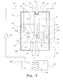
Fig. 3 is a schematic configuration diagram showing a liquid supply system according to Example 1 of the present invention in a usage state. -
Fig. 4 is a schematic configuration diagram showing a liquid supply system according to Example 2 of the present invention in a usage state. - Modes for carrying out the invention will be hereinafter exemplarily described in detail based on embodiments and examples with reference to the drawings. However, dimensions, materials, shapes, relative arrangements and so on of constituent parts described in the embodiments and examples are not intended to limit the scope of this invention to these alone in particular unless otherwise particularly specified.
- The liquid supply system according to an embodiment of the present invention will be described with reference to
Fig. 1 and Fig. 2 . - The overall configuration of the
liquid supply system 100 according to the embodiment and its method of use will be described with reference toFig. 1 . Theliquid supply system 100 according to the embodiment is a system for supplying a cryogenic liquid L to a cooleddevice 300. Note that specific examples of the cryogenic liquid L may be liquid nitrogen or liquid helium. - The
liquid supply system 100 includes a sealedcontainer 110 containing the cryogenic fluid, and apump 120 driven by alinear actuator 130. Inside the sealedcontainer 110, a layer of cryogenic liquid L and a layer of gas G vaporized from the cryogenic liquid L are formed. Thepump 120 is disposed in the cryogenic liquid L contained inside the sealedcontainer 110. Thepump 120 is configured to be driven by arod 140 reciprocated by thelinear actuator 130. Further, aninlet 150 and anoutlet 160 provided on thepump 120 includes a one-way valve 150a and a one-way valve 160a, respectively. - In addition, the
liquid supply system 100 includes a first conduit K1 for directing the cryogenic liquid L pumped out by thepump 120 to the cooleddevice 300 provided outside the sealedcontainer 110, and a second conduit K2 for returning the cryogenic liquid L from the cooleddevice 300 into the sealedcontainer 110. In addition, acooler 200 that cools the liquid to a cryogenic state is provided midway of the first conduit K1. By such a configuration, the cryogenic liquid L cooled by thecooler 200 circulates between theliquid supply system 100 and the cooleddevice 300. - The
liquid supply system 100 according to the embodiment includes afirst relief valve 170 that is connected to the first conduit K1 within the sealedcontainer 110 and releases the cryogenic liquid L into the sealedcontainer 110. Theliquid supply system 100 also includes arelief valve 180 that is connected to thepump 120 within the sealedcontainer 110 and releases the cryogenic liquid L into the sealedcontainer 110. Various known valve structures such as a poppet valve may be employed for thefirst relief valve 170 and thesecond relief valve 180. However, it must be noted that a material that does not suffer low-temperature embrittlement needs to be used for the material that constitutes the valve. For example, austenitic stainless steel may be employed as a metal material that constitutes a valve seat. In addition, polytetrafluoroethylene material or polyimide material may be employed as a material for a valve body. - According to the embodiment configured as described above, since the
liquid supply system 100 includes thefirst relief valve 170, even if the flow of cryogenic liquid L becomes insufficient for some reason, the internal pressure of the first conduit K1 is prevented from exceeding a predetermined level. In addition, since the second relief valve is included 180, even if the flow of cryogenic liquid L becomes insufficient for some reason, the internal pressure of thepump 120 is prevented from exceeding a predetermined level. As a result of these, possible damages to various parts due to an abnormal increase of the internal pressure can be prevented. - In addition, since the
first relief valve 170 and thesecond relief valve 180 are provided inside the sealedcontainer 110, heat is not exchanged with the outside of the sealedcontainer 110 at these relief valves, and the cryogenic liquid L is returned into the sealedcontainer 110 with its temperature kept extremely low. Thus the cooling efficiency can be improved. In addition, functional decline of these relief valves due to the icing or the like can be suppressed. - In addition, it is preferable that set values for the opening pressure of the
first relief valve 170 and thesecond relief valve 180 are set to be lower than a maximum pressure of pulsation inside the first conduit K1 and the second conduit K2 in a case where these relief valves were not provided. Accordingly, the maximum pressure of pulsation can be reduced. Namely, as shown inFig. 2 , by setting Px as the set value for the opening pressure of thefirst relief valve 170 and thesecond relief valve 180, the maximum pressure inside the first conduit K1 and second conduit K2 can be kept equal to or lower than Px. Note that the broken lines in the drawing indicate the pressure fluctuation that would occur if thefirst relief valve 170 andsecond relief valve 180 were not provided. - In addition, the
first relief valve 170 and thesecond relief valve 180 can improve the cooling efficiency as described above, whether they are disposed in the liquid layer or in the gas layer, as long as they are inside the sealedcontainer 110. By disposing these relief valves in the liquid layer, however, an effect of preventing inclusion of gas into the flow passage where the cryogenic liquid L flows can be exhibited as well. Namely, in a case where a gas remains in the flow passage of the cryogenic liquid L, the gas may vibrate and cause troubles such as pulsation. Therefore, if such troubles are to be avoided, thefirst relief valve 170 and thesecond relief valve 180 may be disposed in the liquid layer. - Hereinafter, more specific examples of the embodiment above will be described.
-
Fig. 3 shows Example 1 of the present invention. The configuration and operation thereof are basically the same as those of the embodiment described above, thus the same constituent parts are designated by the same reference signs, and the description thereof will be omitted as appropriate. - In the
liquid supply system 100 according to this Example, a description will be given by using an example in which a cryogenic liquid L is supplied to a cooleddevice 300, which contains asuperconducting coil 320 inside a resin-madecontainer 310. - The
pump 120 in this Example includes ahousing 121 disposed in the cryogenic liquid L contained in a sealedcontainer 110, and abellows 122 disposed inside thishousing 121. The opening of thehousing 121 at its upper end inFig. 3 is closed by asmall bellows 123 to form a sealed space inside. The sealed space inside thehousing 121 is partitioned by thebellows 122 mentioned above, to form a first pump chamber P1 and a second pump chamber P2. - The
housing 121 is provided with afirst inlet 151 that sucks in the cryogenic liquid L in the sealedcontainer 110 into the first pump chamber P1, and afirst outlet 161 that pumps out the sucked cryogenic liquid L into the first conduit K1 that is connected to the outside of the sealedcontainer 110 from inside of the first pump chamber P1. Thehousing 121 is provided with asecond inlet 152 that sucks in the cryogenic liquid L in the sealedcontainer 110 into the second pump chamber P2, and asecond outlet 162 that pumps out the sucked cryogenic liquid L into the first conduit K1 from inside of the second pump chamber P2. In addition, thefirst inlet 151 and thesecond inlet 152 are provided with one-way valves first outlet 161 and thesecond outlet 162 are also provided with one-way valves - In addition, a
rod 140 that is configured to be reciprocated by alinear actuator 130 is entering the sealedcontainer 110 from outside, and its distal end is fixed to the distal end of thebellows 122. Therefore, thebellows 122 expands and contracts as therod 140 reciprocates. - In this Example, a sealed space R is formed around the
rod 140. This sealed space R is formed by a tubular (preferably cylindrical)portion 141 into which therod 140 that extends from outside of the sealedcontainer 110 to thebellows 122 is inserted, andsmall bellows tubular part 141, respectively. Note that thesmall bellows 123 that separates this sealed space R from the second pump chamber P2, and thesmall bellows 111 that separates this sealed space R from the outside space, are both fixed to therod 140 at their distal ends, so that they expand and contract as therod 140 reciprocates. The small bellows 123 and 111 are formed so that their outer diameters are smaller than the outer diameter of thebellows 122. - With the configuration described above, during a process in which the
bellows 122 contracts, the first pump chamber P1 increases in volume while the second pump chamber P2 reduces in volume. Thus, during this process, the cryogenic liquid L is pumped out from inside of the second pump chamber P2 into the first conduit K1 via thesecond outlet 162, and the cryogenic liquid L is sucked into the first pump chamber P1 through thefirst inlet 151. In addition, during a process in which thebellows 122 expands, the first pump chamber P1 decreases in volume while the second pump P2 chamber increases in volume. Thus, during this process, the cryogenic liquid L is sucked into the second pump chamber P2 through thesecond inlet 152, and the cryogenic liquid L is pumped out from inside of the first pump chamber P1 into the first conduit K1 via thefirst outlet 161. As described, the cryogenic liquid L is pumped out to the first conduit K1 in both occasions when thebellows 122 contracts and when it expands. - The
liquid supply system 100 according to this Example also includes afirst relief valve 170 that is connected to the first conduit K1 within the sealedcontainer 110 and releases the cryogenic liquid L into the sealedcontainer 110. In addition, theliquid supply system 100 according to this Example includes asecond relief valve 181 that is connected to the first pump chamber P1 within the sealedcontainer 110 and releases the cryogenic liquid L into the sealedcontainer 110, and asecond relief valve 182 that is connected to the second pump chamber P2 within the sealedcontainer 110 and releases the cryogenic liquid L into the sealedcontainer 110. - As described above, with the
liquid supply system 100 according to this Example, the same operations and effects as those of the embodiment described above can be obtained. Note that, in this Example, the first pump chamber P1 and the second pump chamber P2 are provided, and each of them is provided with thesecond relief valves - In addition, in this Example, the first pump chamber P1 and the second pump chamber P2 are provided and the cryogenic liquid L is pumped out to the first conduit K1 in both occasions when the
bellows 122 contracts and when it expands. Accordingly, the amount of liquid supplied by expansion and contraction of thebellows 122 can be increased (e.g., approximately doubled) as compared to a case where the pumping function is created by only one pump chamber. Thus, the amount of liquid supplied at one time with respect to a desired supply amount can be reduced (e.g., approximately by half) as compared to a case where the pumping function is created by only one pump chamber, and hence the maximum pressure of liquid in the first conduit K1 can be made lower. Therefore, the adverse effects of pressure fluctuation (pulsation) of supplied liquid can be suppressed. - Further, in the case where the pumping function is created by only one pump chamber, the cryogenic liquid L is supplied intermittently, whereas according to this Example, the cryogenic liquid L is supplied in both occasions when the
bellows 122 contracts and when it expands. Therefore, as the cryogenic liquid L is continuously supplied, the pulsation itself can be suppressed. Consequently, as compared to a case where a damper is provided outside the system, space-saving can be achieved, and the cooling efficiency can be improved too because a number of portions where heat exchange occurs is decreased. - Furthermore, this Example adopts a configuration wherein the sealed space R is formed by the
tubular part 141 and a pair ofsmall bellows rod 140 so that they expand and contract as therod 140 reciprocates. Therefore, as the sealed space R is formed without forming any sliding portions, no heat is generated due to friction resistance of sliding. - The
liquid supply system 100 according to Example 2 of the present invention will be described with reference toFig. 4 . This Example shows a case where, based on the configuration of Example 1, a liquid layer and a gas layer are formed in the sealed space R into which the shaft is inserted to give a function as a gas damper. Other features in the configuration and operation thereof are the same as those of the embodiment and Example 1 described above, thus the same constituent parts are designated by the same reference signs, and the description thereof will be omitted. - In this Example, a damping structure for damping the pressure fluctuation (pulsation) of a cryogenic liquid L supplied through a first conduit K1 is provided around a
rod 140. This damping structure includes a tubular (preferably cylindrical)portion 141 into which therod 140 that extends from outside of a sealedcontainer 110 to abellows 122 is inserted, andsmall bellows tubular part 141, respectively. Thetubular part 141 and a pair ofsmall bellows small bellows 123 that separates this sealed space R from the second pump chamber P2, and thesmall bellows 111 that separates this sealed space R from the outside space, are both fixed to therod 140 at their distal ends, so that they expand and contract as therod 140 reciprocates. The small bellows 123 and 111 are formed so that their outer diameters are smaller than the outer diameter of thebellows 122. - Inside the sealed space R, a layer of cryogenic liquid L and a layer of gas G vaporized from the cryogenic liquid L are formed. The temperature is stable in a lower side of the sealed space R (at about 70 K in case of liquid nitrogen), while it becomes higher toward the upper side that is exposed to the outside air. A liquid-gas interface between the layer of cryogenic liquid L and the layer of gas G is formed around a point of saturation temperature (of about 78 K in case of liquid nitrogen).
- A branch conduit K3 branched from the first conduit K1 and connected to this sealed space R is provided. Accordingly, the pressure of the cryogenic liquid L supplied through the first conduit K1 is applied also to the sealed space R, thus the gas inside the sealed space R functions as a damper. Therefore, the pressure fluctuation (pulsation) of the cryogenic liquid L supplied through the first conduit K1 can be damped.
- As described above, with the
liquid supply system 100 according to this Example too, the same operations and effects as those of the embodiment and Example 1 described above can be obtained. In addition, in theliquid supply system 100 according to this Example, a damping structure for damping the pressure fluctuation (pulsation) of the cryogenic liquid L supplied through the first conduit K1 is provided within the system. Therefore, pulsation can be suppressed even more compared to the cases in the embodiment and Example 1 described above. - In addition, in this Example, a structure in which the inside of the
tubular part 141, where therod 140 is inserted, is formed as the sealed space R and the layer of the cryogenic liquid L and the layer of gas G are formed inside this space is employed as the damping structure. Therefore, as the layer of gas G exhibits a function of retarding heat conduction, conduction of heat that is generated in thelinear actuator 130 or atmospheric heat to the cryogenic liquid L is suppressed. In addition, even if heat is conducted to the cryogenic liquid L and the liquid vaporizes, new cryogenic liquid L is constantly supplied, and a cooling effect can be achieved. Thus, it can only lead to an increase in the thickness of the layer of gas G that provides damping function (function as a gas damper) in the sealed space R. Therefore, it is possible to prevent the temperature inside the pump chamber from reaching the point where the cryogenic liquid L vaporizes, and hence the pumping function is not declined. - 100: Liquid supply system, 110: Sealed container, 111, 123: Small bellows, 120: Pump, 121: Container, 122: Bellows, 130: Linear actuator, 140: Rod, 141: Tubular part, 150: Inlet, 150a, 151a, 152a, 160a, 161a, 162a: One-way valve, 151: First inlet, 152: Second inlet, 160: Outlet, 161: First outlet, 162: Second outlet, 170: First relief valve, 180, 181, 182: Second relief valve, 200: Cooler, 300: Cooled device, 310: Container, 320: Superconducting coil, K1: First conduit, K2: Second conduit, K3: Branch conduit, P1: First pump chamber, P2: Second pump chamber, R: Sealed space
Claims (3)
- A liquid supply system, characterized by comprising:a sealed container;a pump disposed in a cryogenic liquid contained inside the sealed container and driven by a linear actuator;a first conduit for directing the cryogenic liquid pumped out by the pump to a cooled device provided outside the sealed container;a second conduit for returning the cryogenic liquid from the cooled device into the sealed container; anda relief valve that is connected to the first conduit within the sealed container and releases the cryogenic liquid into the sealed container.
- The liquid supply system according to claim 1, further comprising a relief valve that is connected to the pump within the sealed container and releases the cryogenic liquid into the sealed container.
- The liquid supply system according to claim 1, wherein the relief valve is disposed in the cryogenic liquid.
Applications Claiming Priority (2)
| Application Number | Priority Date | Filing Date | Title |
|---|---|---|---|
| JP2012273717 | 2012-12-14 | ||
| PCT/JP2013/080818 WO2014091866A1 (en) | 2012-12-14 | 2013-11-14 | Liquid supply system |
Publications (3)
| Publication Number | Publication Date |
|---|---|
| EP2933585A1 true EP2933585A1 (en) | 2015-10-21 |
| EP2933585A4 EP2933585A4 (en) | 2016-08-17 |
| EP2933585B1 EP2933585B1 (en) | 2018-06-06 |
Family
ID=50934162
Family Applications (1)
| Application Number | Title | Priority Date | Filing Date |
|---|---|---|---|
| EP13862998.5A Active EP2933585B1 (en) | 2012-12-14 | 2013-11-14 | Liquid supply system |
Country Status (5)
| Country | Link |
|---|---|
| US (1) | US10047909B2 (en) |
| EP (1) | EP2933585B1 (en) |
| JP (1) | JPWO2014091866A1 (en) |
| CN (1) | CN104641187B (en) |
| WO (1) | WO2014091866A1 (en) |
Families Citing this family (4)
| Publication number | Priority date | Publication date | Assignee | Title |
|---|---|---|---|---|
| US10233913B2 (en) | 2014-07-10 | 2019-03-19 | Eagle Industry Co., Ltd. | Liquid supply system |
| CN106715906B (en) * | 2014-09-22 | 2019-06-07 | 伊格尔工业股份有限公司 | liquid supply system |
| US10578085B1 (en) * | 2017-05-01 | 2020-03-03 | Mark Lee Stang | Sealed modular fluid distribution system |
| CN107808733B (en) * | 2017-12-12 | 2025-01-24 | 合肥中科离子医学技术装备有限公司 | A plug-in infusion tube for cooling low-temperature system |
Family Cites Families (20)
| Publication number | Priority date | Publication date | Assignee | Title |
|---|---|---|---|---|
| US2510632A (en) * | 1945-11-27 | 1950-06-06 | Gen Electric | Machine cooling system |
| US3131713A (en) * | 1960-03-22 | 1964-05-05 | Herrick L Johnston Inc | Pump for cryogenic liquids |
| US3482591A (en) * | 1966-08-31 | 1969-12-09 | Cornelius Co | Pressure regulator valve |
| US4852357A (en) * | 1988-10-14 | 1989-08-01 | Ncr Corporation | Cryogenic liquid pump |
| JPH04335598A (en) * | 1991-05-13 | 1992-11-24 | Fujitsu Ltd | Cooling system |
| US7192426B2 (en) * | 2001-05-31 | 2007-03-20 | Endocare, Inc. | Cryogenic system |
| US6640556B2 (en) * | 2001-09-19 | 2003-11-04 | Westport Research Inc. | Method and apparatus for pumping a cryogenic fluid from a storage tank |
| US6575712B1 (en) * | 2001-09-28 | 2003-06-10 | Slavcho Slavchev | Air compressor system |
| US6581390B2 (en) * | 2001-10-29 | 2003-06-24 | Chart Inc. | Cryogenic fluid delivery system |
| US7083612B2 (en) * | 2003-01-15 | 2006-08-01 | Cryodynamics, Llc | Cryotherapy system |
| JP2004286404A (en) * | 2003-03-25 | 2004-10-14 | Sumitomo Heavy Ind Ltd | Cooling liquid circulating device and cooling unit |
| US8511100B2 (en) | 2005-06-30 | 2013-08-20 | General Electric Company | Cooling of superconducting devices by liquid storage and refrigeration unit |
| KR100990072B1 (en) * | 2005-09-02 | 2010-10-29 | 주식회사 만도 | Anti-roller |
| JP2008151269A (en) * | 2006-12-18 | 2008-07-03 | Ebara Corp | Pressure container safety device |
| JP4886552B2 (en) | 2007-02-28 | 2012-02-29 | 株式会社Ihi | Superconducting coil cooling device and vent plate used therefor |
| GB2453126B (en) * | 2007-09-26 | 2013-02-06 | Intelligent Energy Ltd | Fuel cell system |
| US8784409B2 (en) * | 2008-09-03 | 2014-07-22 | Endocare, Inc. | Cryogenic system and method of use |
| US8671700B2 (en) * | 2009-01-21 | 2014-03-18 | Endocare, Inc. | High pressure cryogenic fluid generator |
| US8991446B2 (en) * | 2011-01-26 | 2015-03-31 | GM Global Technology Operations LLC | Pump assisted refilling system for LPG fuel tanks |
| JP5844348B2 (en) | 2011-03-15 | 2016-01-13 | イーグル工業株式会社 | Liquid supply system |
-
2013
- 2013-11-14 JP JP2014551940A patent/JPWO2014091866A1/en active Pending
- 2013-11-14 EP EP13862998.5A patent/EP2933585B1/en active Active
- 2013-11-14 CN CN201380048284.5A patent/CN104641187B/en active Active
- 2013-11-14 US US14/431,619 patent/US10047909B2/en active Active
- 2013-11-14 WO PCT/JP2013/080818 patent/WO2014091866A1/en not_active Ceased
Also Published As
| Publication number | Publication date |
|---|---|
| US20150276131A1 (en) | 2015-10-01 |
| US10047909B2 (en) | 2018-08-14 |
| JPWO2014091866A1 (en) | 2017-01-05 |
| WO2014091866A1 (en) | 2014-06-19 |
| EP2933585B1 (en) | 2018-06-06 |
| CN104641187A (en) | 2015-05-20 |
| EP2933585A4 (en) | 2016-08-17 |
| CN104641187B (en) | 2017-02-08 |
Similar Documents
| Publication | Publication Date | Title |
|---|---|---|
| EP2687793B1 (en) | Liquid supply system | |
| EP2933585B1 (en) | Liquid supply system | |
| JP2007518026A (en) | Apparatus and method for holding and removing cryogenic liquid while suppressing heat leakage | |
| JP4886552B2 (en) | Superconducting coil cooling device and vent plate used therefor | |
| JP6457517B2 (en) | Liquid supply system | |
| US9476314B2 (en) | Gas seal assembly for cryogenic liquid turbomachines | |
| US8671700B2 (en) | High pressure cryogenic fluid generator | |
| CN102834678A (en) | Cooling system and cooling method | |
| US20140109599A1 (en) | Cryogenic Pumps | |
| KR20140098824A (en) | Cryogenic pumps | |
| US20170175729A1 (en) | Cooling Device Equipped with a Compressor Device | |
| WO2020054770A1 (en) | Compressor, lng tanker, and compression cylinder | |
| JP6229207B2 (en) | Device for reducing vibration of pulse tube refrigerators used in magnetic resonance diagnostic imaging equipment | |
| JP2008281234A (en) | Cold storage type refrigerating machine and pulse tube refrigerating machine | |
| US11231029B2 (en) | Compressor for a cooling device and a refrigeration machine | |
| CN110192032A (en) | liquid supply system | |
| EP3019747B1 (en) | Cryogenic pump flange | |
| JP2002310539A (en) | Expansion valve | |
| CN205842089U (en) | Pulsation damper device | |
| JPWO2018143425A1 (en) | Thermal insulation structure and liquid supply system | |
| JP4146419B2 (en) | Low temperature liquefied gas pressure pump | |
| EP4582732A1 (en) | Method for removing boil off gas when storing cryogenic fluid and corresponding system | |
| JP2005183440A (en) | Superconducting material cooling device | |
| EP4636299A1 (en) | Liquefied gas transportation system | |
| CN109563826B (en) | liquid supply system |
Legal Events
| Date | Code | Title | Description |
|---|---|---|---|
| PUAI | Public reference made under article 153(3) epc to a published international application that has entered the european phase |
Free format text: ORIGINAL CODE: 0009012 |
|
| 17P | Request for examination filed |
Effective date: 20150331 |
|
| AK | Designated contracting states |
Kind code of ref document: A1 Designated state(s): AL AT BE BG CH CY CZ DE DK EE ES FI FR GB GR HR HU IE IS IT LI LT LU LV MC MK MT NL NO PL PT RO RS SE SI SK SM TR |
|
| AX | Request for extension of the european patent |
Extension state: BA ME |
|
| DAX | Request for extension of the european patent (deleted) | ||
| A4 | Supplementary search report drawn up and despatched |
Effective date: 20160715 |
|
| RIC1 | Information provided on ipc code assigned before grant |
Ipc: F25D 3/10 20060101ALI20160712BHEP Ipc: F25D 29/00 20060101ALI20160712BHEP Ipc: H01L 23/44 20060101ALI20160712BHEP Ipc: F25D 17/02 20060101ALI20160712BHEP Ipc: F25B 9/00 20060101AFI20160712BHEP |
|
| STAA | Information on the status of an ep patent application or granted ep patent |
Free format text: STATUS: EXAMINATION IS IN PROGRESS |
|
| 17Q | First examination report despatched |
Effective date: 20170214 |
|
| GRAP | Despatch of communication of intention to grant a patent |
Free format text: ORIGINAL CODE: EPIDOSNIGR1 |
|
| STAA | Information on the status of an ep patent application or granted ep patent |
Free format text: STATUS: GRANT OF PATENT IS INTENDED |
|
| INTG | Intention to grant announced |
Effective date: 20171220 |
|
| GRAS | Grant fee paid |
Free format text: ORIGINAL CODE: EPIDOSNIGR3 |
|
| GRAA | (expected) grant |
Free format text: ORIGINAL CODE: 0009210 |
|
| STAA | Information on the status of an ep patent application or granted ep patent |
Free format text: STATUS: THE PATENT HAS BEEN GRANTED |
|
| AK | Designated contracting states |
Kind code of ref document: B1 Designated state(s): AL AT BE BG CH CY CZ DE DK EE ES FI FR GB GR HR HU IE IS IT LI LT LU LV MC MK MT NL NO PL PT RO RS SE SI SK SM TR |
|
| REG | Reference to a national code |
Ref country code: GB Ref legal event code: FG4D |
|
| REG | Reference to a national code |
Ref country code: CH Ref legal event code: EP Ref country code: AT Ref legal event code: REF Ref document number: 1006547 Country of ref document: AT Kind code of ref document: T Effective date: 20180615 |
|
| REG | Reference to a national code |
Ref country code: IE Ref legal event code: FG4D |
|
| REG | Reference to a national code |
Ref country code: DE Ref legal event code: R096 Ref document number: 602013038697 Country of ref document: DE |
|
| REG | Reference to a national code |
Ref country code: NL Ref legal event code: MP Effective date: 20180606 |
|
| REG | Reference to a national code |
Ref country code: LT Ref legal event code: MG4D |
|
| PG25 | Lapsed in a contracting state [announced via postgrant information from national office to epo] |
Ref country code: BG Free format text: LAPSE BECAUSE OF FAILURE TO SUBMIT A TRANSLATION OF THE DESCRIPTION OR TO PAY THE FEE WITHIN THE PRESCRIBED TIME-LIMIT Effective date: 20180906 Ref country code: FI Free format text: LAPSE BECAUSE OF FAILURE TO SUBMIT A TRANSLATION OF THE DESCRIPTION OR TO PAY THE FEE WITHIN THE PRESCRIBED TIME-LIMIT Effective date: 20180606 Ref country code: NO Free format text: LAPSE BECAUSE OF FAILURE TO SUBMIT A TRANSLATION OF THE DESCRIPTION OR TO PAY THE FEE WITHIN THE PRESCRIBED TIME-LIMIT Effective date: 20180906 Ref country code: CY Free format text: LAPSE BECAUSE OF FAILURE TO SUBMIT A TRANSLATION OF THE DESCRIPTION OR TO PAY THE FEE WITHIN THE PRESCRIBED TIME-LIMIT Effective date: 20180606 Ref country code: ES Free format text: LAPSE BECAUSE OF FAILURE TO SUBMIT A TRANSLATION OF THE DESCRIPTION OR TO PAY THE FEE WITHIN THE PRESCRIBED TIME-LIMIT Effective date: 20180606 Ref country code: SE Free format text: LAPSE BECAUSE OF FAILURE TO SUBMIT A TRANSLATION OF THE DESCRIPTION OR TO PAY THE FEE WITHIN THE PRESCRIBED TIME-LIMIT Effective date: 20180606 Ref country code: LT Free format text: LAPSE BECAUSE OF FAILURE TO SUBMIT A TRANSLATION OF THE DESCRIPTION OR TO PAY THE FEE WITHIN THE PRESCRIBED TIME-LIMIT Effective date: 20180606 |
|
| PG25 | Lapsed in a contracting state [announced via postgrant information from national office to epo] |
Ref country code: LV Free format text: LAPSE BECAUSE OF FAILURE TO SUBMIT A TRANSLATION OF THE DESCRIPTION OR TO PAY THE FEE WITHIN THE PRESCRIBED TIME-LIMIT Effective date: 20180606 Ref country code: RS Free format text: LAPSE BECAUSE OF FAILURE TO SUBMIT A TRANSLATION OF THE DESCRIPTION OR TO PAY THE FEE WITHIN THE PRESCRIBED TIME-LIMIT Effective date: 20180606 Ref country code: GR Free format text: LAPSE BECAUSE OF FAILURE TO SUBMIT A TRANSLATION OF THE DESCRIPTION OR TO PAY THE FEE WITHIN THE PRESCRIBED TIME-LIMIT Effective date: 20180907 Ref country code: HR Free format text: LAPSE BECAUSE OF FAILURE TO SUBMIT A TRANSLATION OF THE DESCRIPTION OR TO PAY THE FEE WITHIN THE PRESCRIBED TIME-LIMIT Effective date: 20180606 |
|
| REG | Reference to a national code |
Ref country code: AT Ref legal event code: MK05 Ref document number: 1006547 Country of ref document: AT Kind code of ref document: T Effective date: 20180606 |
|
| PG25 | Lapsed in a contracting state [announced via postgrant information from national office to epo] |
Ref country code: NL Free format text: LAPSE BECAUSE OF FAILURE TO SUBMIT A TRANSLATION OF THE DESCRIPTION OR TO PAY THE FEE WITHIN THE PRESCRIBED TIME-LIMIT Effective date: 20180606 |
|
| PG25 | Lapsed in a contracting state [announced via postgrant information from national office to epo] |
Ref country code: EE Free format text: LAPSE BECAUSE OF FAILURE TO SUBMIT A TRANSLATION OF THE DESCRIPTION OR TO PAY THE FEE WITHIN THE PRESCRIBED TIME-LIMIT Effective date: 20180606 Ref country code: PL Free format text: LAPSE BECAUSE OF FAILURE TO SUBMIT A TRANSLATION OF THE DESCRIPTION OR TO PAY THE FEE WITHIN THE PRESCRIBED TIME-LIMIT Effective date: 20180606 Ref country code: IS Free format text: LAPSE BECAUSE OF FAILURE TO SUBMIT A TRANSLATION OF THE DESCRIPTION OR TO PAY THE FEE WITHIN THE PRESCRIBED TIME-LIMIT Effective date: 20181006 Ref country code: AT Free format text: LAPSE BECAUSE OF FAILURE TO SUBMIT A TRANSLATION OF THE DESCRIPTION OR TO PAY THE FEE WITHIN THE PRESCRIBED TIME-LIMIT Effective date: 20180606 Ref country code: RO Free format text: LAPSE BECAUSE OF FAILURE TO SUBMIT A TRANSLATION OF THE DESCRIPTION OR TO PAY THE FEE WITHIN THE PRESCRIBED TIME-LIMIT Effective date: 20180606 Ref country code: CZ Free format text: LAPSE BECAUSE OF FAILURE TO SUBMIT A TRANSLATION OF THE DESCRIPTION OR TO PAY THE FEE WITHIN THE PRESCRIBED TIME-LIMIT Effective date: 20180606 Ref country code: SK Free format text: LAPSE BECAUSE OF FAILURE TO SUBMIT A TRANSLATION OF THE DESCRIPTION OR TO PAY THE FEE WITHIN THE PRESCRIBED TIME-LIMIT Effective date: 20180606 |
|
| PG25 | Lapsed in a contracting state [announced via postgrant information from national office to epo] |
Ref country code: SM Free format text: LAPSE BECAUSE OF FAILURE TO SUBMIT A TRANSLATION OF THE DESCRIPTION OR TO PAY THE FEE WITHIN THE PRESCRIBED TIME-LIMIT Effective date: 20180606 Ref country code: IT Free format text: LAPSE BECAUSE OF FAILURE TO SUBMIT A TRANSLATION OF THE DESCRIPTION OR TO PAY THE FEE WITHIN THE PRESCRIBED TIME-LIMIT Effective date: 20180606 |
|
| REG | Reference to a national code |
Ref country code: DE Ref legal event code: R097 Ref document number: 602013038697 Country of ref document: DE |
|
| PLBE | No opposition filed within time limit |
Free format text: ORIGINAL CODE: 0009261 |
|
| STAA | Information on the status of an ep patent application or granted ep patent |
Free format text: STATUS: NO OPPOSITION FILED WITHIN TIME LIMIT |
|
| 26N | No opposition filed |
Effective date: 20190307 |
|
| PG25 | Lapsed in a contracting state [announced via postgrant information from national office to epo] |
Ref country code: SI Free format text: LAPSE BECAUSE OF FAILURE TO SUBMIT A TRANSLATION OF THE DESCRIPTION OR TO PAY THE FEE WITHIN THE PRESCRIBED TIME-LIMIT Effective date: 20180606 Ref country code: DK Free format text: LAPSE BECAUSE OF FAILURE TO SUBMIT A TRANSLATION OF THE DESCRIPTION OR TO PAY THE FEE WITHIN THE PRESCRIBED TIME-LIMIT Effective date: 20180606 |
|
| REG | Reference to a national code |
Ref country code: CH Ref legal event code: PL |
|
| PG25 | Lapsed in a contracting state [announced via postgrant information from national office to epo] |
Ref country code: MC Free format text: LAPSE BECAUSE OF FAILURE TO SUBMIT A TRANSLATION OF THE DESCRIPTION OR TO PAY THE FEE WITHIN THE PRESCRIBED TIME-LIMIT Effective date: 20180606 Ref country code: LU Free format text: LAPSE BECAUSE OF NON-PAYMENT OF DUE FEES Effective date: 20181114 |
|
| REG | Reference to a national code |
Ref country code: BE Ref legal event code: MM Effective date: 20181130 |
|
| REG | Reference to a national code |
Ref country code: IE Ref legal event code: MM4A |
|
| PG25 | Lapsed in a contracting state [announced via postgrant information from national office to epo] |
Ref country code: CH Free format text: LAPSE BECAUSE OF NON-PAYMENT OF DUE FEES Effective date: 20181130 Ref country code: LI Free format text: LAPSE BECAUSE OF NON-PAYMENT OF DUE FEES Effective date: 20181130 |
|
| PG25 | Lapsed in a contracting state [announced via postgrant information from national office to epo] |
Ref country code: FR Free format text: LAPSE BECAUSE OF NON-PAYMENT OF DUE FEES Effective date: 20181130 Ref country code: IE Free format text: LAPSE BECAUSE OF NON-PAYMENT OF DUE FEES Effective date: 20181114 |
|
| PG25 | Lapsed in a contracting state [announced via postgrant information from national office to epo] |
Ref country code: BE Free format text: LAPSE BECAUSE OF NON-PAYMENT OF DUE FEES Effective date: 20181130 Ref country code: AL Free format text: LAPSE BECAUSE OF FAILURE TO SUBMIT A TRANSLATION OF THE DESCRIPTION OR TO PAY THE FEE WITHIN THE PRESCRIBED TIME-LIMIT Effective date: 20180606 |
|
| PG25 | Lapsed in a contracting state [announced via postgrant information from national office to epo] |
Ref country code: MT Free format text: LAPSE BECAUSE OF NON-PAYMENT OF DUE FEES Effective date: 20181114 |
|
| PG25 | Lapsed in a contracting state [announced via postgrant information from national office to epo] |
Ref country code: TR Free format text: LAPSE BECAUSE OF FAILURE TO SUBMIT A TRANSLATION OF THE DESCRIPTION OR TO PAY THE FEE WITHIN THE PRESCRIBED TIME-LIMIT Effective date: 20180606 |
|
| PG25 | Lapsed in a contracting state [announced via postgrant information from national office to epo] |
Ref country code: PT Free format text: LAPSE BECAUSE OF FAILURE TO SUBMIT A TRANSLATION OF THE DESCRIPTION OR TO PAY THE FEE WITHIN THE PRESCRIBED TIME-LIMIT Effective date: 20180606 |
|
| PG25 | Lapsed in a contracting state [announced via postgrant information from national office to epo] |
Ref country code: MK Free format text: LAPSE BECAUSE OF NON-PAYMENT OF DUE FEES Effective date: 20180606 Ref country code: HU Free format text: LAPSE BECAUSE OF FAILURE TO SUBMIT A TRANSLATION OF THE DESCRIPTION OR TO PAY THE FEE WITHIN THE PRESCRIBED TIME-LIMIT; INVALID AB INITIO Effective date: 20131114 |
|
| PGFP | Annual fee paid to national office [announced via postgrant information from national office to epo] |
Ref country code: DE Payment date: 20241001 Year of fee payment: 12 |
|
| PGFP | Annual fee paid to national office [announced via postgrant information from national office to epo] |
Ref country code: GB Payment date: 20241001 Year of fee payment: 12 |