EP2933473A1 - Startup control device for outboard motor, startup control method for outboard motor, and program - Google Patents
Startup control device for outboard motor, startup control method for outboard motor, and program Download PDFInfo
- Publication number
- EP2933473A1 EP2933473A1 EP13862838.3A EP13862838A EP2933473A1 EP 2933473 A1 EP2933473 A1 EP 2933473A1 EP 13862838 A EP13862838 A EP 13862838A EP 2933473 A1 EP2933473 A1 EP 2933473A1
- Authority
- EP
- European Patent Office
- Prior art keywords
- outboard motor
- authentication
- instruction
- electric power
- security
- Prior art date
- Legal status (The legal status is an assumption and is not a legal conclusion. Google has not performed a legal analysis and makes no representation as to the accuracy of the status listed.)
- Granted
Links
Images

Classifications
-
- F—MECHANICAL ENGINEERING; LIGHTING; HEATING; WEAPONS; BLASTING
- F02—COMBUSTION ENGINES; HOT-GAS OR COMBUSTION-PRODUCT ENGINE PLANTS
- F02N—STARTING OF COMBUSTION ENGINES; STARTING AIDS FOR SUCH ENGINES, NOT OTHERWISE PROVIDED FOR
- F02N11/00—Starting of engines by means of electric motors
- F02N11/08—Circuits specially adapted for starting of engines
- F02N11/0803—Circuits specially adapted for starting of engines characterised by means for initiating engine start or stop
- F02N11/0807—Remote means
-
- B—PERFORMING OPERATIONS; TRANSPORTING
- B63—SHIPS OR OTHER WATERBORNE VESSELS; RELATED EQUIPMENT
- B63H—MARINE PROPULSION OR STEERING
- B63H20/00—Outboard propulsion units, e.g. outboard motors or Z-drives; Arrangements thereof on vessels
-
- B—PERFORMING OPERATIONS; TRANSPORTING
- B63—SHIPS OR OTHER WATERBORNE VESSELS; RELATED EQUIPMENT
- B63H—MARINE PROPULSION OR STEERING
- B63H21/00—Use of propulsion power plant or units on vessels
- B63H21/21—Control means for engine or transmission, specially adapted for use on marine vessels
-
- B—PERFORMING OPERATIONS; TRANSPORTING
- B63—SHIPS OR OTHER WATERBORNE VESSELS; RELATED EQUIPMENT
- B63J—AUXILIARIES ON VESSELS
- B63J99/00—Subject matter not provided for in other groups of this subclass
-
- F—MECHANICAL ENGINEERING; LIGHTING; HEATING; WEAPONS; BLASTING
- F02—COMBUSTION ENGINES; HOT-GAS OR COMBUSTION-PRODUCT ENGINE PLANTS
- F02N—STARTING OF COMBUSTION ENGINES; STARTING AIDS FOR SUCH ENGINES, NOT OTHERWISE PROVIDED FOR
- F02N11/00—Starting of engines by means of electric motors
- F02N11/08—Circuits specially adapted for starting of engines
- F02N11/0803—Circuits specially adapted for starting of engines characterised by means for initiating engine start or stop
-
- B—PERFORMING OPERATIONS; TRANSPORTING
- B63—SHIPS OR OTHER WATERBORNE VESSELS; RELATED EQUIPMENT
- B63B—SHIPS OR OTHER WATERBORNE VESSELS; EQUIPMENT FOR SHIPPING
- B63B17/00—Vessels parts, details, or accessories, not otherwise provided for
- B63B2017/0009—Methods or devices specially adapted for preventing theft, or unauthorized use of vessels, or parts or accessories thereof, other than by using locks
-
- B—PERFORMING OPERATIONS; TRANSPORTING
- B63—SHIPS OR OTHER WATERBORNE VESSELS; RELATED EQUIPMENT
- B63H—MARINE PROPULSION OR STEERING
- B63H20/00—Outboard propulsion units, e.g. outboard motors or Z-drives; Arrangements thereof on vessels
- B63H20/14—Transmission between propulsion power unit and propulsion element
-
- B—PERFORMING OPERATIONS; TRANSPORTING
- B63—SHIPS OR OTHER WATERBORNE VESSELS; RELATED EQUIPMENT
- B63H—MARINE PROPULSION OR STEERING
- B63H21/00—Use of propulsion power plant or units on vessels
- B63H21/21—Control means for engine or transmission, specially adapted for use on marine vessels
- B63H21/213—Levers or the like for controlling the engine or the transmission, e.g. single hand control levers
-
- F—MECHANICAL ENGINEERING; LIGHTING; HEATING; WEAPONS; BLASTING
- F02—COMBUSTION ENGINES; HOT-GAS OR COMBUSTION-PRODUCT ENGINE PLANTS
- F02B—INTERNAL-COMBUSTION PISTON ENGINES; COMBUSTION ENGINES IN GENERAL
- F02B61/00—Adaptations of engines for driving vehicles or for driving propellers; Combinations of engines with gearing
- F02B61/04—Adaptations of engines for driving vehicles or for driving propellers; Combinations of engines with gearing for driving propellers
- F02B61/045—Adaptations of engines for driving vehicles or for driving propellers; Combinations of engines with gearing for driving propellers for marine engines
-
- F—MECHANICAL ENGINEERING; LIGHTING; HEATING; WEAPONS; BLASTING
- F02—COMBUSTION ENGINES; HOT-GAS OR COMBUSTION-PRODUCT ENGINE PLANTS
- F02P—IGNITION, OTHER THAN COMPRESSION IGNITION, FOR INTERNAL-COMBUSTION ENGINES; TESTING OF IGNITION TIMING IN COMPRESSION-IGNITION ENGINES
- F02P11/00—Safety means for electric spark ignition, not otherwise provided for
Definitions
- the present invention relates to a start control device for an outboard motor, a start control method for an outboard motor, and a program.
- the present invention is suitable for being used in a case where cancellation and execution of security of an outboard motor are conducted by using an electronic key.
- an ignition switch provided to an outboard motor main body or provided in an operation cabin has been conventionally used. Concretely, by inserting a key into the ignition switch, and rotating the ignition switch in stages, the ignition is turned on, and then a start SW is turned on, which starts the outboard motor.
- Patent Literature 1 only when an encryption code received from a portable machine coincides with a collation code, a steering lock is unlocked so that an operation is allowed, which enables to improve the security.
- Patent Literature 1 Japanese Laid-open Patent Publication No. 2006-137338
- Patent Literature 1 One switch is used in the engine start system in Patent Literature 1, in which an authentication of the portable machine is performed and a steering lock is unlocked by pressing-down the switch for the first time, an authentication of the portable machine is performed again to turn on the system by pressing-down the switch for the second time, and the engine is started by pressing-down the switch for the third time.
- a user does not always want to start the engine, and it is also possible to suppose a case where the user wants to turn off the system, from the state where the system is turned on, without starting the engine.
- the present invention is made in view of the problems as described above, and an object thereof is to enable, even in an outboard motor system in which cancellation and execution of security of an outboard motor are conducted in accordance with an authentication of a portable machine, a state where electric power is supplied to the outboard motor (ignition-on state) to shift to a state where the supply of electric power to the outboard motor is stopped (ignition-off state) without starting the outboard motor.
- a start control device for an outboard motor of the present invention is a start control device for an outboard motor performing a control to start and stop the outboard motor in accordance with an instruction made by a boat operator, the start control device for the outboard motor including: an authentication means performing an authentication of a portable machine carried by the boat operator via a communication part in accordance with an operation of a first switch made by the boat operator; an electric power supply instruction means instructing a supply of electric power to the outboard motor based on a success of the authentication of the portable machine performed by the authentication means; a security cancellation instruction means instructing a cancellation of security of the outboard motor based on the success of the authentication of the portable machine performed by the authentication means; a determination means determining whether or not an emergency switch is on when the first switch is operated by the boat operator in the state where the electric power is supplied to the outboard motor in accordance with the instruction made by the electric power supply instruction means, and the security of the outboard motor is cancelled in accordance with the instruction made by the security cancellation instruction means; a start instruction means
- a start control method for an outboard motor of the present invention is a start control method for an outboard motor performing a control to start and stop the outboard motor in accordance with an instruction made by a boat operator, the start control method for the outboard motor including: an authentication step of performing an authentication of a portable machine carried by the boat operator via a communication part in accordance with an operation of a first switch made by the boat operator; an electric power supply instruction step of instructing a supply of electric power to the outboard motor based on a success of the authentication of the portable machine performed by the authentication step; a security cancellation instruction step of instructing a cancellation of security of the outboard motor based on the success of the authentication of the portable machine performed by the authentication step; a determination step of determining whether or not an emergency switch is on when the first switch is operated by the boat operator in the state where the electric power is supplied to the outboard motor in accordance with the instruction made by the electric power supply instruction step, and the security of the outboard motor is cancelled in accordance with the instruction made by the security cancellation instruction step;
- a program of the present invention is a program for performing a control to start and stop an outboard motor in accordance with an instruction made by a boat operator, the program causing a computer to execute: an authentication step of performing an authentication of a portable machine carried by the boat operator via a communication part in accordance with an operation of a first switch made by the boat operator; an electric power supply instruction step of instructing a supply of electric power to the outboard motor based on a success of the authentication of the portable machine performed by the authentication step; a security cancellation instruction step of instructing a cancellation of security of the outboard motor based on the success of the authentication of the portable machine performed by the authentication step; a determination step of determining whether or not an emergency switch is on when the first switch is operated by the boat operator in the state where the electric power is supplied to the outboard motor in accordance with the instruction made by the electric power supply instruction step, and the security of the outboard motor is cancelled in accordance with the instruction made by the security cancellation instruction step; a start instruction step of instructing the start of the outboard motor
- the present invention it is possible to make a state where electric power is supplied to an outboard motor (ignition-on state) shift to a state where the supply of electric power to the outboard motor is stopped (ignition-off state) without starting the outboard motor.
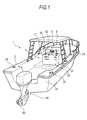
- Fig. 1 is a perspective view of a boat when seen from a diagonally rear direction. As illustrated in Fig. 1 , to a transom 2a located on a rear part of a hull 2 of a boat 1, an outboard motor 40 having a propeller 48 is attached via a bracket device.
- An operation cabin 4 is provided in an almost middle part of the hull 2.
- a steering handle 5 for steering the boat 1 and a remote control lever 6 are disposed.
- a start control device 20 for an outboard motor 40 is disposed. The start control device 20 performs a control to start or stop the outboard motor 40, and performs a control to cancel or execute a security of the outboard motor 40.
- Fig. 1 illustrates, out of components of the start control device 20, a communication part 24, a battery SW 28, a start SW 30, and an emergency SW 31.
- the start control device 20 performs wireless communication with a later-described portable machine 10 carried by a boat operator, via the communication part 24.
- the start control device 20 performs an authentication based on an encryption code received from the portable machine 10, and in accordance with a result of the authentication, it instructs the outboard motor 40 to cancel the security or execute the security. Further, the start control device 20 starts the authentication in accordance with an operation of the start SW 30 made by the boat operator, and instructs the outboard motor 40 to start or stop. Further, the start control device 20 instructs the outboard motor 40 to stop in accordance with an operation of the emergency SW 31 made by the boat operator in an emergency.
- the communication part 24 of the present embodiment is disposed in, other than the operation cabin 4, a plurality of places such as a bow and a stern. Specifically, a plurality of the communication parts 24 are disposed so that the communication with the start control device 20 can be performed as long as the boat operator who carries the portable machine 10 exists in the hull 2. Therefore, even if the boat operator who carries the portable machine 10 does not exist in the operation cabin 4, as long as he/she exists in the hull 2, the authentication can be conducted with the portable machine 10 even if another person operates the start SW 30. Therefore, even the other person can steer the outboard motor 40.
- Fig. 2 is a block diagram illustrating a configuration of an outboard motor system 100.
- the outboard motor system 100 has the portable machine 10, the start control device 20, and the outboard motor 40.
- the portable machine 10 is a so-called electronic key capable of being carried by the boat operator.
- the portable machine 10 can perform wireless communication with the start control device 20.
- the portable machine 10 has a control part 11, a storage part 12, a communication part 13, a battery 14, an up SW 15, a down SW 16 and the like.
- the control part 11 controls the entire portable machine 10.
- the control part 11 transmits, in accordance with an instruction made by the start control device 20, an encryption code stored in the storage part 12 to the start control device 20.
- the storage part 12 stores a program executed by the control part 11, the encryption code and the like.
- the communication part 13 is an antenna, for example, and transmits/receives data to/from the communication part 24 of the start control device 20.
- the battery 14 supplies electric power to the control part 11 and the like.
- the up SW 15 and the down SW 16 are switches which are pressed-down when the boat operator wants to adjust a power of the outboard motor 40 at a time of berthing the boat 1, and the like.
- the up SW 15 and the down SW 16 are switches which are pressed-down when the boat operator wants to adjust an engine speed of the outboard motor 40 within a low speed range.
- the up SW 15 is a switch which is pressed-down when the boat operator wants to increase the engine speed within the low speed range.
- the down SW 16 is a switch which is pressed-down when the boat operator wants to decrease the engine speed within the low speed range.
- the start control device 20 can communicate with the portable machine 10 and the outboard motor 40.
- the start control device 20 has a smart unit 21, the communication part 24, a display part 25, a notification part 26, a power source relay 27, a battery SW 28, a battery 29, a start SW 30, an emergency SW 31 and the like. Further, the smart unit 21 configures a so-called computer including a control part 22 and a storage part 23.
- the control part 22 controls the entire start control device 20.
- the control part 22 performs an authentication based on the encryption code received from the portable machine 10, and instructs, in accordance with a result of the authentication, the outboard motor 40 to cancel the security or to execute the security. Further, in accordance with an operation of the start SW 30, the control part 22 instructs the outboard motor 40 to start or stop.
- the storage part 23 stores a program executed by the control part 22, an encryption code for collation (referred to as a collation code, hereinafter) and the like.
- the communication part 24 is an antenna, for example, and transmits/receives data to/from the communication part 13 of the portable machine 10.
- the display part 25 is a liquid crystal monitor, for example, and displays a driven state and the like of the outboard motor 40.
- the notification part 26 is a buzzer, an LED or the like, for example, and performs notification to the boat operator using a sound or light.
- the power source relay 27 is disposed in the middle of a power source cable 33 which connects the battery 29 and the outboard motor 40.
- the power source relay 27 is controlled to be turned on or off by the control part 22.
- the battery SW 28 is disposed between the battery 29 and the smart unit 21. When the battery SW 28 is turned on by the boat operator, the electric power is supplied from the battery 29 to the smart unit 21. Further, when the battery SW 28 is turned off by the boat operator, the supply of electric power from the battery 29 to the smart unit 21 is stopped.
- the battery 29 also supplies electric power to the start control device 20, the outboard motor 40, and a later-described accessory 50.
- the start SW 30 is, for example, a push switch as a first switch.
- the start SW 30 is a switch which is pressed-down when the boat operator starts or stops the outboard motor 40.
- the emergency SW (emergency switch) 31 is a switch for stopping the outboard motor 40 in an emergency, and an insertion/extraction member can be inserted/extracted into/from the switch.
- the emergency SW 31 In a state where the insertion/extraction member is inserted into the emergency SW 31, the emergency SW 31 is off, and it is possible to continuously drive the outboard motor 40.
- the emergency SW 31 In a state where the insertion/extraction member is extracted from the emergency SW 31, the emergency SW 31 is turned on, and the control part 22 stops the outboard motor 40.
- the insertion/extraction member is connected to the boat operator via a code. Therefore, if the boat operator falls into water, for example, the insertion/extraction member is extracted from the emergency SW 31, so that the emergency SW 31 is turned on, resulting in that the outboard motor 40 stops.
- the outboard motor 40 can perform communication with the start control device 20 via a communication cable 32. Although explanation will be made on a case where the outboard motor 40 of the present embodiment rotates the propeller 48 using an engine, the present invention is not limited to this case, and can also be applied to an electric outboard motor which rotates the propeller 48 using a motor.
- the outboard motor 40 has an ECU 41, an injector 44, an ignition coil 45, a starter relay 46, a starter motor 47 and the like. Further, the ECU 41 is configured by including a control part 42 and a storage part 43.
- the control part 42 controls the entire outboard motor 40. In accordance with an instruction made by the start control device 20, the control part 42 cancels the security of the outboard motor 40 or executes the security of the outboard motor 40.
- the security includes a mechanical locking method of locking a predetermined member of the outboard motor 40, an electrical locking method in which the control part 42 prevents the operation of the predetermined member, and the like.
- the control part 42 starts or stops the outboard motor 40 in accordance with an instruction made by the start control device 20.
- the storage part 43 stores a program executed by the control part 42 and the like.
- the injector 44 injects a fuel in accordance with an instruction made by the control part 42.
- the ignition coil 45 ignites an ignition plug in accordance with an instruction made by the control part 42.
- the starter relay 46 is turned on in accordance with an instruction made by the control part 42, to thereby drive the starter motor 47.
- the starter motor 47 forcibly rotates a crankshaft to start the outboard motor 40.
- the accessory 50 can be connected to the outboard motor system 100.
- the accessory 50 is, for example, a fish finder or the like.
- the accessory 50 is connected to the power source cable 33 between the power source relay 27 and the outboard motor 40.
- the battery SW 28 is turned on and the power source relay 27 is turned on, the electric power is supplied to the accessory 50 from the battery 29.
- the accessory 50 can be used even if the outboard motor 40 is not started.
- the boat operator sometimes wants to stop, from the state where the electric power is supplied from the battery 29 to the outboard motor 40, the supply of electric power to the outboard motor 40 without starting the outboard motor 40.
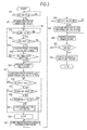
- FIG. 3 a flowchart illustrated in Fig. 3 .
- the flowchart illustrated in Fig. 3 is realized when the control part 22 of the smart unit 21 in the start control device 20 executes the program stored in the storage part 23. Further, processing conducted by the portable machine 10 is realized when the control part 11 of the portable machine 10 executes the program stored in the storage part 12, and processing conducted by the outboard motor 40 is realized when the control part 42 of the ECU 41 of the outboard motor 40 executes the program stored in the storage part 43.
- step S10 the control part 22 of the smart unit 21 determines whether or not the battery SW 28 is turned on by the boat operator. When the battery SW 28 is turned on, the process proceeds to step S11.
- step S11 the control part 22 activates the entire start control device 20 including the smart unit 21 with the use of the electric power supplied from the battery 29.
- step S12 the control part 22 determines whether or not the start SW 30 is turned on by the boat operator. When the start SW 30 is turned on, the process proceeds to step S13, and when it is not turned on, the control part 22 waits until the start SW 30 is turned on.
- step S13 the control part 22 checks the security, and determines whether or not the security is being executed. For example, by reading information stored in the storage part 23 indicating that the security is executed, the control part 22 can determine whether or not the security is being executed. When the security is being executed, the process proceeds to step S14, and when the security is not being executed, the process proceeds to step S16.
- step S14 the control part 22 performs wireless communication with the portable machine 10 via the communication part 24, and performs an authentication of the portable machine 10.
- This processing corresponds to one example of processing performed by an authentication means.
- the plurality of communication parts 24 are disposed in the hull 2, so that as long as the boat operator who carries the portable machine 10 exists in the hull 2, it is possible to perform the wireless communication with the portable machine 10. Therefore, even if a person who operates the start SW 30 in step S12 is not the boat operator who carries the portable machine 10, the authentication is conducted.
- the control part 22 transmits, to the portable machine 10, an instruction indicating the transmission of encryption code.
- the control part 11 of the portable machine 10 transmits, in accordance with the instruction, the encryption code stored in the storage part 12 to the start control device 20.
- step S15 the control part 22 performs an authentication whether or not the received encryption code coincides with a collation code stored in the storage part 23.
- the process proceeds to step S16.
- the process returns to step S12. Therefore, when the authentication does not succeed, the process cannot proceed to the next step S16.
- step S16 the control part 22 instructs the power source relay 27 to supply electric power to the outboard motor 40.
- This processing corresponds to one example of processing performed by an electric power supply instruction means.
- the control part 22 turns on the power source relay 27, the electric power is supplied to the outboard motor 40 from the battery 29 via the power source cable 33. Under this state, the electric power is supplied also to the accessory 50 from the battery 29, so that the boat operator can use the accessory 50.
- a state in which the electric power is supplied to the outboard motor 40 and the accessory 50 without starting the outboard motor 40 as described above is set to be referred to as an ignition-on state.
- a state where the power source relay 27 is in an off state, and the electric power is not supplied to the outboard motor 40 and the accessory 50 from the battery 29 is set to be referred to as an ignition-off state.
- step S17 the control part 22 performs communication with the ECU 41 of the outboard motor 40 via the communication cable 32, and instructs the outboard motor 40 to cancel the security.
- This processing corresponds to one example of processing performed by a security cancellation instruction means.
- the control part 22 transmits, to the outboard motor 40, an order to cancel the security.
- the control part 42 of the ECU 41 of the outboard motor 40 cancels the security in accordance with the order. Note that when the security is not being executed, the control part 22 omits step S17.
- step S18 the control part 22 determines whether or not the start SW 30 is turned on by the boat operator.
- the boat operator presses-down the start SW 30 for starting the outboard motor 40 from the ignition-on state and a case where the boat operator presses-down the start SW 30 for returning the ignition-on state to the ignition-off state after finishing the use of the accessory 50, for example, exist.
- the start SW 30 is turned on
- the process proceeds to step S19, and when it is not turned on, the control part 22 waits until the start SW 30 is turned on.
- step S19 the control part 22 performs communication with the outboard motor 40, and determines whether or not the outboard motor 40 is being driven. Concretely, the control part 22 obtains information regarding an engine speed from the control part 22 of the outboard motor 40, and determines whether or not the engine speed is 0 (zero).
- step S20 When the outboard motor 40 is not being driven, the process proceeds to step S20.
- step S22 When the outboard motor 40 is being driven, the process proceeds to step S22.
- step S19 for the first time after starting the flowchart in Fig. 3 , the process proceeds to step S20 since the outboard motor 40 is not being driven.
- step S20 the control part 22 determines whether or not the emergency SW 31 is on.
- This processing corresponds to one example of processing performed by a determination means.
- the process proceeds to step S21, and the control part 22 transmits, to the outboard motor 40, an instruction of starting the outboard motor 40.
- This processing corresponds to one example of processing performed by a start instruction means.
- the control part 42 of the outboard motor 40 starts the outboard motor 40 in accordance with the instruction. Concretely, the control part 42 injects the fuel with the use of the injector 44 while rotating the starter motor 47 via the starter relay 46, and ignites the ignition plug via the ignition coil 45, to thereby start the engine.
- step S23 the control part 22 makes the process proceed to processing of later-described step S23 and thereafter in which the supply of electric power to the outboard motor 40 is stopped.
- the outboard motor 40 when the emergency SW 31 is off at the time of turning on the start SW 30 under the ignition-on state, the outboard motor 40 is started, and when the emergency SW 31 is on, the outboard motor 40 is not started, and the ignition-on state shifts to the ignition-off state. Therefore, through a relatively simple operation in which the boat operator presses-down the start SW 30 under the state where the insertion/extraction member is extracted from the emergency SW 31, it is possible to make the ignition-on state shift to the ignition-off state without starting the outboard motor 40.
- step S21 After the outboard motor 40 is started in step S21, the process returns to step S18, and the control part 22 determines whether or not the start SW 30 is turned on. When the start SW 30 is turned on, the process proceeds to step S19. In step S19, it is determined that the outboard motor 40 is being driven, and the process proceeds to step S22.
- step S22 the control part 22 transmits, to the outboard motor 40, an instruction of stopping the outboard motor 40.
- This processing corresponds to one example of processing performed by a stop instruction means.
- the control part 42 of the outboard motor 40 stops the outboard motor 40 in accordance with the instruction. Concretely, the control part 42 stops the injection conducted by the injector 44, and stops the ignition using the ignition plug via the ignition coil 45. As described above, in the state where the outboard motor 40 is being driven, the boat operator can stop the outboard motor 40 by turning on the start SW 30.
- step S23 the control part 22 performs wireless communication with the portable machine 10, and performs an authentication of the portable machine 10. This processing is similar to that in step S14. Therefore, also in step S23, the authentication is performed as long as the boat operator who carries the portable machine 10 exists in the hull 2.
- step S24 the control part 22 performs an authentication whether or not the received encryption code coincides with the collation code stored in the storage part 23.
- the process proceeds to step S25. Note that in the case where the encryption code and the collation code do not coincide with each other and the authentication does not succeed, and the like, the process proceeds to step S26.
- step S25 the control part 22 performs communication with the ECU 41 of the outboard motor 40, and instructs the outboard motor 40 to execute the security.
- the control part 22 transmits, to the outboard motor 40, an order to execute the security.
- the control part 42 of the ECU 41 executes the security in accordance with the order.
- the control part 22 Upon receiving, from the control part 42 of the ECU 41, information indicating that the security is executed, the control part 22 notifies the boat operator that the security is executed, via the notification part 26. Further, the control part 22 can store the information indicating that the security is executed, in the storage part 23. Note that when the authentication does not succeed in step S24 described above, the security in step S25 is not executed.
- step S26 the control part 22 turns off the power source relay 27.
- the power source relay 27 is turned off, the shift to the ignition-off state in which the supply of electric power to the outboard motor 40 and the accessory 50 is stopped is realized.
- step S27 the control part 22 determines whether or not the battery SW 28 is turned off by the boat operator. When the battery SW 28 is turned off, the process proceeds to step S28. When the battery SW 28 is not turned off, the process returns to step S12, in which the determination whether or not the start SW 30 is turned on is conducted again.
- step S28 the control part 22 turns off the power source of the start control device 20 including the smart unit 21, resulting in that the processing of the outboard motor system 100 is terminated.
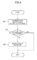
- FIG. 4 a flowchart in Fig. 4 is realized when the control part 22 of the smart unit 21 in the start control device 20 executes the program stored in the storage part 23.
- the control part 22 executes the processing in the flowchart illustrated in Fig. 4 at fixed intervals.
- step S30 the control part 22 performs wireless communication with the portable machine 10 via the communication part 24, and performs an authentication of the portable machine 10. This processing is similar to that in step S14. Therefore, also in step S30, the authentication is performed as long as the boat operator who carries the portable machine 10 exists in the operation cabin 4.
- step S31 the control part 22 performs an authentication whether or not the received encryption code coincides with the collation code stored in the storage part 23.
- the processing is terminated.
- the authentication does not succeed, the process proceeds to step S32.
- step S32 the control part 22 performs communication with the ECU 41 of the outboard motor 40, and gives an instruction of decreasing the power of the outboard motor 40.
- This processing corresponds to one example of processing performed by a power instruction means.
- the control part 42 of the ECU 41 of the outboard motor 40 decreases the power of the outboard motor 40, namely, it decreases the engine speed, in accordance with the instruction.
- the reason why the control part 22 performs the authentication of the portable machine 10 after starting the outboard motor 40 is because the case where the boat operator drops the portable machine 10 in water is supposed. Specifically, the case where the authentication does not succeed also includes a case where the portable machine 10 is dropped in water and thus the control part 22 cannot receive the encryption code from the portable machine 10. By taking such a case into consideration, the control part 22 performs the authentication with the portable machine 10 at fixed intervals, and when the authentication does not succeed, by decreasing the power of the outboard motor 40, it is possible to make it easy for the boat operator to perform searching on a surface of water in the periphery of the outboard motor 40.
- the present embodiment through a relatively simple operation such that the boat operator presses-down the start SW 30 in the state where the insertion/extraction member is extracted from the emergency SW 31, it is possible to shift the ignition-on state to the ignition-off state. Therefore, even when the boat operator uses only the accessory 50, for example, under the ignition-on state, it is possible to shift the ignition-on state to the ignition-off state in which the supply of electric power to the outboard motor 40 is stopped, without starting the outboard motor 40.
- the emergency SW 31 is normally a switch used after starting the outboard motor 40, and normally, it is not used before starting the outboard motor 40. Therefore, by performing, with the use of the emergency SW 31 which is used only after the start of the outboard motor 40, the switching whether to start the outboard motor 40 or to stop the supply of electric power to the outboard motor 40, it is not necessary to newly add a switch for performing the switching, and thus there is no chance of increasing the product cost.
- the plurality of communication parts 24 each capable of performing the wireless communication with the portable machine 10 are disposed in the hull 2, it is possible to perform the wireless communication with the portable machine 10 as long as the boat operator who carries the portable machine 10 exists in the hull 2. Therefore, as long as the boat operator who carries the portable machine 10 exists in the hull 2, even another person can perform the operation for making the outboard motor 40 cancel the security or execute the security, resulting in that a convenience of the outboard motor system 100 can be improved.
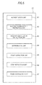
- Fig. 5 is a diagram illustrating one example of a functional configuration of the start control device for the outboard motor.
- the functional configuration illustrated in Fig. 5 is realized when the control part 22 executes the program stored in the storage part 23.
- the start control device 20 is configured by including an authentication unit 61, an electric power supply instruction unit 62, a security cancellation instruction unit 63, a determination unit 64, a start instruction unit 65, a stop instruction unit 66, and a power instruction unit 67.
- the authentication unit 61 performs the authentication of the portable machine 10 carried by the boat operator via the communication part 24.
- the electric power supply instruction unit 62 instructs the supply of electric power to the outboard motor 40.
- the security cancellation instruction unit 63 instructs the cancellation of security of the outboard motor 40.
- the determination unit 64 determines, when the start SW 30 is turned on, whether or not the emergency SW 31 is on.
- the start instruction unit 65 instructs the start of the outboard motor 40.
- the stop instruction unit 66 instructs the stop of the supply of electric power to the outboard motor 40.
- the power instruction unit 67 instructs the outboard motor 40 to increase or decrease the power.
- the present invention is not limited to this case.
- step S12 and step S18 it is also possible to determine whether or not a long pressing of the up SW 15 or the down SW 16 is conducted, and it is also possible to determine whether or not a switch which is different from the up SW 15 or the down SW 16 and is newly provided to the portable machine 10, is turned on.
- the above-described embodiment describes the case where the control part 22 turns on or off the power source relay 27 as the instruction of supplying electric power or stopping the supply of electric power to the outboard motor 40.
- the present invention is not limited to this case, and it is also possible to design such that the power source relay 27 is omitted, the control part 22 directly instructs the battery 29 to supply electric power or stop the supply of electric power to the outboard motor 40, and the battery 29 supplies electric power or stops the supply of electric power to the outboard motor 40 in accordance with the instruction.
- the processing after the outboard motor 40 starts includes processing in which the control part 22 adjusts the power of the outboard motor 40 in accordance with the signal of the up SW 15 or the down SW 16 received from the portable machine 10.
- the control part 22 transmits, every time it receives the signal of the up SW 15 or the down SW 16, an instruction of increasing or decreasing the engine speed (power) of the outboard motor 40 within the low speed range (within a low power range).
- the control part 42 of the ECU 41 of the outboard motor 40 increases or decreases, in accordance with the instruction, the engine speed (power) of the outboard motor 40 within the low speed range (within the low power range).
- the present invention includes the above-described program and a computer readable recording medium which records the program.
- the present invention can be utilized when cancellation and execution of security of an outboard motor are conducted by using an electronic key.
Landscapes
- Engineering & Computer Science (AREA)
- Chemical & Material Sciences (AREA)
- Combustion & Propulsion (AREA)
- Mechanical Engineering (AREA)
- General Engineering & Computer Science (AREA)
- Ocean & Marine Engineering (AREA)
- Combined Controls Of Internal Combustion Engines (AREA)
- Lock And Its Accessories (AREA)
Abstract
Description
- The present invention relates to a start control device for an outboard motor, a start control method for an outboard motor, and a program. In particular, the present invention is suitable for being used in a case where cancellation and execution of security of an outboard motor are conducted by using an electronic key.
- In order to start or stop an outboard motor, an ignition switch provided to an outboard motor main body or provided in an operation cabin has been conventionally used. Concretely, by inserting a key into the ignition switch, and rotating the ignition switch in stages, the ignition is turned on, and then a start SW is turned on, which starts the outboard motor.
- In recent years, a demand for improving a security of a boat and an outboard motor has been increasing. However, in the outboard motor which is started by the ignition switch described above, it cannot be always said that the perfect security is provided. Therefore, it can be considered that, with respect to the boat and the outboard motor as well, an engine start system in which a key is not required as disclosed in Patent Literature 1, for example, is employed to improve the security. In Patent Literature 1, only when an encryption code received from a portable machine coincides with a collation code, a steering lock is unlocked so that an operation is allowed, which enables to improve the security.
- Patent Literature 1: Japanese Laid-open Patent Publication No.
2006-137338 - One switch is used in the engine start system in Patent Literature 1, in which an authentication of the portable machine is performed and a steering lock is unlocked by pressing-down the switch for the first time, an authentication of the portable machine is performed again to turn on the system by pressing-down the switch for the second time, and the engine is started by pressing-down the switch for the third time. However, a user does not always want to start the engine, and it is also possible to suppose a case where the user wants to turn off the system, from the state where the system is turned on, without starting the engine. In this case, in a four-wheel vehicle and the like, for example, it can be considered to switch whether to start the engine or to turn off the system in accordance with whether or not a brake pedal is depressed at the time of pressing-down the one switch. For example, it is possible to employ a method such that the engine is started by pressing-down the switch while depressing the brake pedal from the state where the system is turned on, and the system is turned off by pressing-down the switch without depressing the brake pedal from the state where the system is turned on.
- However, since the brake pedal is not provided to the outboard motor, it is difficult to perform the switching with a method similar to that of the four-wheel vehicle. Further, when a switch or the like is newly added for switching the start of the engine and the turning-off of the system, a product cost is increased.
- The present invention is made in view of the problems as described above, and an object thereof is to enable, even in an outboard motor system in which cancellation and execution of security of an outboard motor are conducted in accordance with an authentication of a portable machine, a state where electric power is supplied to the outboard motor (ignition-on state) to shift to a state where the supply of electric power to the outboard motor is stopped (ignition-off state) without starting the outboard motor.
- A start control device for an outboard motor of the present invention is a start control device for an outboard motor performing a control to start and stop the outboard motor in accordance with an instruction made by a boat operator, the start control device for the outboard motor including: an authentication means performing an authentication of a portable machine carried by the boat operator via a communication part in accordance with an operation of a first switch made by the boat operator; an electric power supply instruction means instructing a supply of electric power to the outboard motor based on a success of the authentication of the portable machine performed by the authentication means; a security cancellation instruction means instructing a cancellation of security of the outboard motor based on the success of the authentication of the portable machine performed by the authentication means; a determination means determining whether or not an emergency switch is on when the first switch is operated by the boat operator in the state where the electric power is supplied to the outboard motor in accordance with the instruction made by the electric power supply instruction means, and the security of the outboard motor is cancelled in accordance with the instruction made by the security cancellation instruction means; a start instruction means instructing the start of the outboard motor when the determination means determines that the emergency switch is not on; and a stop instruction means instructing a stop of the supply of electric power to the outboard motor when the determination means determines that the emergency switch is on.
- A start control method for an outboard motor of the present invention is a start control method for an outboard motor performing a control to start and stop the outboard motor in accordance with an instruction made by a boat operator, the start control method for the outboard motor including: an authentication step of performing an authentication of a portable machine carried by the boat operator via a communication part in accordance with an operation of a first switch made by the boat operator; an electric power supply instruction step of instructing a supply of electric power to the outboard motor based on a success of the authentication of the portable machine performed by the authentication step; a security cancellation instruction step of instructing a cancellation of security of the outboard motor based on the success of the authentication of the portable machine performed by the authentication step; a determination step of determining whether or not an emergency switch is on when the first switch is operated by the boat operator in the state where the electric power is supplied to the outboard motor in accordance with the instruction made by the electric power supply instruction step, and the security of the outboard motor is cancelled in accordance with the instruction made by the security cancellation instruction step; a start instruction step of instructing the start of the outboard motor when the determination step determines that the emergency switch is not on; and a stop instruction step of instructing a stop of the supply of electric power to the outboard motor when the determination step determines that the emergency switch is on.
- A program of the present invention is a program for performing a control to start and stop an outboard motor in accordance with an instruction made by a boat operator, the program causing a computer to execute: an authentication step of performing an authentication of a portable machine carried by the boat operator via a communication part in accordance with an operation of a first switch made by the boat operator; an electric power supply instruction step of instructing a supply of electric power to the outboard motor based on a success of the authentication of the portable machine performed by the authentication step; a security cancellation instruction step of instructing a cancellation of security of the outboard motor based on the success of the authentication of the portable machine performed by the authentication step; a determination step of determining whether or not an emergency switch is on when the first switch is operated by the boat operator in the state where the electric power is supplied to the outboard motor in accordance with the instruction made by the electric power supply instruction step, and the security of the outboard motor is cancelled in accordance with the instruction made by the security cancellation instruction step; a start instruction step of instructing the start of the outboard motor when the determination step determines that the emergency switch is not on; and a stop instruction step of instructing a stop of the supply of electric power to the outboard motor when the determination step determines that the emergency switch is on.
- According to the present invention, it is possible to make a state where electric power is supplied to an outboard motor (ignition-on state) shift to a state where the supply of electric power to the outboard motor is stopped (ignition-off state) without starting the outboard motor.
-
- [
Fig. 1] Fig. 1 is a perspective view of a boat when seen from a diagonally rear direction. - [
Fig. 2] Fig. 2 is a block diagram illustrating a configuration of an outboard motor system. - [
Fig. 3] Fig. 3 is a flowchart illustrating processing of a start control device for an outboard motor. - [
Fig. 4] Fig. 4 is a flowchart illustrating processing of the start control device for the outboard motor. - [
Fig. 5] Fig. 5 is a diagram illustrating a functional configuration of the start control device. - Hereinafter, a preferred embodiment of the present invention will be described with reference to the attached drawings.
-
Fig. 1 is a perspective view of a boat when seen from a diagonally rear direction. As illustrated inFig. 1 , to atransom 2a located on a rear part of ahull 2 of a boat 1, anoutboard motor 40 having apropeller 48 is attached via a bracket device. - An operation cabin 4 is provided in an almost middle part of the
hull 2. In the operation cabin 4, asteering handle 5 for steering the boat 1 and aremote control lever 6 are disposed. Further, in the operation cabin 4, astart control device 20 for anoutboard motor 40 is disposed. Thestart control device 20 performs a control to start or stop theoutboard motor 40, and performs a control to cancel or execute a security of theoutboard motor 40. -
Fig. 1 illustrates, out of components of thestart control device 20, acommunication part 24, abattery SW 28, astart SW 30, and anemergency SW 31. Thestart control device 20 performs wireless communication with a later-describedportable machine 10 carried by a boat operator, via thecommunication part 24. Thestart control device 20 performs an authentication based on an encryption code received from theportable machine 10, and in accordance with a result of the authentication, it instructs theoutboard motor 40 to cancel the security or execute the security. Further, thestart control device 20 starts the authentication in accordance with an operation of thestart SW 30 made by the boat operator, and instructs theoutboard motor 40 to start or stop. Further, thestart control device 20 instructs theoutboard motor 40 to stop in accordance with an operation of theemergency SW 31 made by the boat operator in an emergency. - Here, as illustrated in
Fig. 1 , thecommunication part 24 of the present embodiment is disposed in, other than the operation cabin 4, a plurality of places such as a bow and a stern. Specifically, a plurality of thecommunication parts 24 are disposed so that the communication with thestart control device 20 can be performed as long as the boat operator who carries theportable machine 10 exists in thehull 2. Therefore, even if the boat operator who carries theportable machine 10 does not exist in the operation cabin 4, as long as he/she exists in thehull 2, the authentication can be conducted with theportable machine 10 even if another person operates thestart SW 30. Therefore, even the other person can steer theoutboard motor 40. -
Fig. 2 is a block diagram illustrating a configuration of anoutboard motor system 100. InFig. 2 , components same as those inFig. 1 are denoted by the same reference numerals. Hereinafter, a concrete configuration of theoutboard motor system 100 will be described. Theoutboard motor system 100 has theportable machine 10, thestart control device 20, and theoutboard motor 40. - The
portable machine 10 is a so-called electronic key capable of being carried by the boat operator. Theportable machine 10 can perform wireless communication with thestart control device 20. Theportable machine 10 has acontrol part 11, astorage part 12, acommunication part 13, abattery 14, an upSW 15, a downSW 16 and the like. - The
control part 11 controls the entireportable machine 10. Thecontrol part 11 transmits, in accordance with an instruction made by thestart control device 20, an encryption code stored in thestorage part 12 to thestart control device 20. Thestorage part 12 stores a program executed by thecontrol part 11, the encryption code and the like. Thecommunication part 13 is an antenna, for example, and transmits/receives data to/from thecommunication part 24 of thestart control device 20. Thebattery 14 supplies electric power to thecontrol part 11 and the like. - The up
SW 15 and the downSW 16 are switches which are pressed-down when the boat operator wants to adjust a power of theoutboard motor 40 at a time of berthing the boat 1, and the like. Concretely, the upSW 15 and the downSW 16 are switches which are pressed-down when the boat operator wants to adjust an engine speed of theoutboard motor 40 within a low speed range. The upSW 15 is a switch which is pressed-down when the boat operator wants to increase the engine speed within the low speed range. The downSW 16 is a switch which is pressed-down when the boat operator wants to decrease the engine speed within the low speed range. When the upSW 15 or thedown SW 16 is pressed-down, thecontrol part 11 transmits a signal corresponding to the upSW 15 or thedown SW 16 to thestart control device 20 via thecommunication part 13. - The
start control device 20 can communicate with theportable machine 10 and theoutboard motor 40. Thestart control device 20 has asmart unit 21, thecommunication part 24, adisplay part 25, anotification part 26, apower source relay 27, abattery SW 28, abattery 29, astart SW 30, anemergency SW 31 and the like. Further, thesmart unit 21 configures a so-called computer including acontrol part 22 and astorage part 23. - The
control part 22 controls the entirestart control device 20. Thecontrol part 22 performs an authentication based on the encryption code received from theportable machine 10, and instructs, in accordance with a result of the authentication, theoutboard motor 40 to cancel the security or to execute the security. Further, in accordance with an operation of thestart SW 30, thecontrol part 22 instructs theoutboard motor 40 to start or stop. Thestorage part 23 stores a program executed by thecontrol part 22, an encryption code for collation (referred to as a collation code, hereinafter) and the like. Thecommunication part 24 is an antenna, for example, and transmits/receives data to/from thecommunication part 13 of theportable machine 10. Thedisplay part 25 is a liquid crystal monitor, for example, and displays a driven state and the like of theoutboard motor 40. Thenotification part 26 is a buzzer, an LED or the like, for example, and performs notification to the boat operator using a sound or light. - The
power source relay 27 is disposed in the middle of apower source cable 33 which connects thebattery 29 and theoutboard motor 40. Thepower source relay 27 is controlled to be turned on or off by thecontrol part 22. Thebattery SW 28 is disposed between thebattery 29 and thesmart unit 21. When thebattery SW 28 is turned on by the boat operator, the electric power is supplied from thebattery 29 to thesmart unit 21. Further, when thebattery SW 28 is turned off by the boat operator, the supply of electric power from thebattery 29 to thesmart unit 21 is stopped. Thebattery 29 also supplies electric power to thestart control device 20, theoutboard motor 40, and a later-describedaccessory 50. - The
start SW 30 is, for example, a push switch as a first switch. Thestart SW 30 is a switch which is pressed-down when the boat operator starts or stops theoutboard motor 40. - The emergency SW (emergency switch) 31 is a switch for stopping the
outboard motor 40 in an emergency, and an insertion/extraction member can be inserted/extracted into/from the switch. In a state where the insertion/extraction member is inserted into theemergency SW 31, theemergency SW 31 is off, and it is possible to continuously drive theoutboard motor 40. On the other hand, in a state where the insertion/extraction member is extracted from theemergency SW 31, theemergency SW 31 is turned on, and thecontrol part 22 stops theoutboard motor 40. Normally, the insertion/extraction member is connected to the boat operator via a code. Therefore, if the boat operator falls into water, for example, the insertion/extraction member is extracted from theemergency SW 31, so that theemergency SW 31 is turned on, resulting in that theoutboard motor 40 stops. - The
outboard motor 40 can perform communication with thestart control device 20 via acommunication cable 32. Although explanation will be made on a case where theoutboard motor 40 of the present embodiment rotates thepropeller 48 using an engine, the present invention is not limited to this case, and can also be applied to an electric outboard motor which rotates thepropeller 48 using a motor. Theoutboard motor 40 has anECU 41, aninjector 44, anignition coil 45, astarter relay 46, astarter motor 47 and the like. Further, theECU 41 is configured by including acontrol part 42 and astorage part 43. - The
control part 42 controls the entireoutboard motor 40. In accordance with an instruction made by thestart control device 20, thecontrol part 42 cancels the security of theoutboard motor 40 or executes the security of theoutboard motor 40. Here, the security includes a mechanical locking method of locking a predetermined member of theoutboard motor 40, an electrical locking method in which thecontrol part 42 prevents the operation of the predetermined member, and the like. Further, thecontrol part 42 starts or stops theoutboard motor 40 in accordance with an instruction made by thestart control device 20. Thestorage part 43 stores a program executed by thecontrol part 42 and the like. Theinjector 44 injects a fuel in accordance with an instruction made by thecontrol part 42. Theignition coil 45 ignites an ignition plug in accordance with an instruction made by thecontrol part 42. Thestarter relay 46 is turned on in accordance with an instruction made by thecontrol part 42, to thereby drive thestarter motor 47. Thestarter motor 47 forcibly rotates a crankshaft to start theoutboard motor 40. - Further, to the
outboard motor system 100, theaccessory 50 can be connected. Theaccessory 50 is, for example, a fish finder or the like. Theaccessory 50 is connected to thepower source cable 33 between thepower source relay 27 and theoutboard motor 40. When thebattery SW 28 is turned on and thepower source relay 27 is turned on, the electric power is supplied to the accessory 50 from thebattery 29. Specifically, theaccessory 50 can be used even if theoutboard motor 40 is not started. - In the
outboard motor system 100 configured as described above, the boat operator sometimes wants to stop, from the state where the electric power is supplied from thebattery 29 to theoutboard motor 40, the supply of electric power to theoutboard motor 40 without starting theoutboard motor 40. This concretely indicates a case where the boat operator wants to use only theaccessory 50 without starting theoutboard motor 40, and to stop, after using theaccessory 50, the supply of electric power to theaccessory 50 and theoutboard motor 40, and the like. In theoutboard motor system 100 of the present embodiment, it is possible to stop the supply of electric power to theaccessory 50 and theoutboard motor 40, through a relatively simple operation conducted by the boat operator. - Hereinafter, processing performed by the
outboard motor system 100 of the present embodiment will be described with reference to a flowchart illustrated inFig. 3 . The flowchart illustrated inFig. 3 is realized when thecontrol part 22 of thesmart unit 21 in thestart control device 20 executes the program stored in thestorage part 23. Further, processing conducted by theportable machine 10 is realized when thecontrol part 11 of theportable machine 10 executes the program stored in thestorage part 12, and processing conducted by theoutboard motor 40 is realized when thecontrol part 42 of theECU 41 of theoutboard motor 40 executes the program stored in thestorage part 43. - First, in step S10, the
control part 22 of thesmart unit 21 determines whether or not thebattery SW 28 is turned on by the boat operator. When thebattery SW 28 is turned on, the process proceeds to step S11. - In step S11, the
control part 22 activates the entirestart control device 20 including thesmart unit 21 with the use of the electric power supplied from thebattery 29. - In step S12, the
control part 22 determines whether or not thestart SW 30 is turned on by the boat operator. When thestart SW 30 is turned on, the process proceeds to step S13, and when it is not turned on, thecontrol part 22 waits until thestart SW 30 is turned on. - In step S13, the
control part 22 checks the security, and determines whether or not the security is being executed. For example, by reading information stored in thestorage part 23 indicating that the security is executed, thecontrol part 22 can determine whether or not the security is being executed. When the security is being executed, the process proceeds to step S14, and when the security is not being executed, the process proceeds to step S16. - In step S14, the
control part 22 performs wireless communication with theportable machine 10 via thecommunication part 24, and performs an authentication of theportable machine 10. This processing corresponds to one example of processing performed by an authentication means. As described above, the plurality ofcommunication parts 24 are disposed in thehull 2, so that as long as the boat operator who carries theportable machine 10 exists in thehull 2, it is possible to perform the wireless communication with theportable machine 10. Therefore, even if a person who operates thestart SW 30 in step S12 is not the boat operator who carries theportable machine 10, the authentication is conducted. Concretely, thecontrol part 22 transmits, to theportable machine 10, an instruction indicating the transmission of encryption code. Thecontrol part 11 of theportable machine 10 transmits, in accordance with the instruction, the encryption code stored in thestorage part 12 to thestart control device 20. - In step S15, the
control part 22 performs an authentication whether or not the received encryption code coincides with a collation code stored in thestorage part 23. When the encryption code and the collation code coincide with each other and the authentication is succeeded, the process proceeds to step S16. On the other hand, in the case where the encryption code and the collation code do not coincide with each other and the authentication does not succeed, and the like, the process returns to step S12. Therefore, when the authentication does not succeed, the process cannot proceed to the next step S16. - In step S16, the
control part 22 instructs thepower source relay 27 to supply electric power to theoutboard motor 40. This processing corresponds to one example of processing performed by an electric power supply instruction means. Concretely, when thecontrol part 22 turns on thepower source relay 27, the electric power is supplied to theoutboard motor 40 from thebattery 29 via thepower source cable 33. Under this state, the electric power is supplied also to the accessory 50 from thebattery 29, so that the boat operator can use theaccessory 50. A state in which the electric power is supplied to theoutboard motor 40 and theaccessory 50 without starting theoutboard motor 40 as described above is set to be referred to as an ignition-on state. On the other hand, a state where thepower source relay 27 is in an off state, and the electric power is not supplied to theoutboard motor 40 and the accessory 50 from thebattery 29 is set to be referred to as an ignition-off state. - In step S17, the
control part 22 performs communication with theECU 41 of theoutboard motor 40 via thecommunication cable 32, and instructs theoutboard motor 40 to cancel the security. This processing corresponds to one example of processing performed by a security cancellation instruction means. Concretely, thecontrol part 22 transmits, to theoutboard motor 40, an order to cancel the security. Thecontrol part 42 of theECU 41 of theoutboard motor 40 cancels the security in accordance with the order. Note that when the security is not being executed, thecontrol part 22 omits step S17. - In step S18, the
control part 22 determines whether or not thestart SW 30 is turned on by the boat operator. Here, a case where the boat operator presses-down thestart SW 30 for starting theoutboard motor 40 from the ignition-on state, and a case where the boat operator presses-down thestart SW 30 for returning the ignition-on state to the ignition-off state after finishing the use of theaccessory 50, for example, exist. When thestart SW 30 is turned on, the process proceeds to step S19, and when it is not turned on, thecontrol part 22 waits until thestart SW 30 is turned on. - In step S19, the
control part 22 performs communication with theoutboard motor 40, and determines whether or not theoutboard motor 40 is being driven. Concretely, thecontrol part 22 obtains information regarding an engine speed from thecontrol part 22 of theoutboard motor 40, and determines whether or not the engine speed is 0 (zero). When theoutboard motor 40 is not being driven, the process proceeds to step S20. When theoutboard motor 40 is being driven, the process proceeds to step S22. When the process proceeds to step S19 for the first time after starting the flowchart inFig. 3 , the process proceeds to step S20 since theoutboard motor 40 is not being driven. - In step S20, the
control part 22 determines whether or not theemergency SW 31 is on. This processing corresponds to one example of processing performed by a determination means. When theemergency SW 31 is not on, the process proceeds to step S21, and thecontrol part 22 transmits, to theoutboard motor 40, an instruction of starting theoutboard motor 40. This processing corresponds to one example of processing performed by a start instruction means. Thecontrol part 42 of theoutboard motor 40 starts theoutboard motor 40 in accordance with the instruction. Concretely, thecontrol part 42 injects the fuel with the use of theinjector 44 while rotating thestarter motor 47 via thestarter relay 46, and ignites the ignition plug via theignition coil 45, to thereby start the engine. - On the other hand, when the
emergency SW 31 is on, the process proceeds to step S23, and thecontrol part 22 makes the process proceed to processing of later-described step S23 and thereafter in which the supply of electric power to theoutboard motor 40 is stopped. - In the
outboard motor system 100 of the present embodiment, when theemergency SW 31 is off at the time of turning on thestart SW 30 under the ignition-on state, theoutboard motor 40 is started, and when theemergency SW 31 is on, theoutboard motor 40 is not started, and the ignition-on state shifts to the ignition-off state. Therefore, through a relatively simple operation in which the boat operator presses-down thestart SW 30 under the state where the insertion/extraction member is extracted from theemergency SW 31, it is possible to make the ignition-on state shift to the ignition-off state without starting theoutboard motor 40. - Next, after the
outboard motor 40 is started in step S21, the process returns to step S18, and thecontrol part 22 determines whether or not thestart SW 30 is turned on. When thestart SW 30 is turned on, the process proceeds to step S19. In step S19, it is determined that theoutboard motor 40 is being driven, and the process proceeds to step S22. - In step S22, the
control part 22 transmits, to theoutboard motor 40, an instruction of stopping theoutboard motor 40. This processing corresponds to one example of processing performed by a stop instruction means. Thecontrol part 42 of theoutboard motor 40 stops theoutboard motor 40 in accordance with the instruction. Concretely, thecontrol part 42 stops the injection conducted by theinjector 44, and stops the ignition using the ignition plug via theignition coil 45. As described above, in the state where theoutboard motor 40 is being driven, the boat operator can stop theoutboard motor 40 by turning on thestart SW 30. - In step S23, the
control part 22 performs wireless communication with theportable machine 10, and performs an authentication of theportable machine 10. This processing is similar to that in step S14. Therefore, also in step S23, the authentication is performed as long as the boat operator who carries theportable machine 10 exists in thehull 2. - In step S24, the
control part 22 performs an authentication whether or not the received encryption code coincides with the collation code stored in thestorage part 23. When the encryption code and the collation code coincide with each other and the authentication is succeeded, the process proceeds to step S25. Note that in the case where the encryption code and the collation code do not coincide with each other and the authentication does not succeed, and the like, the process proceeds to step S26. - In step S25, the
control part 22 performs communication with theECU 41 of theoutboard motor 40, and instructs theoutboard motor 40 to execute the security. Concretely, thecontrol part 22 transmits, to theoutboard motor 40, an order to execute the security. Thecontrol part 42 of theECU 41 executes the security in accordance with the order. Upon receiving, from thecontrol part 42 of theECU 41, information indicating that the security is executed, thecontrol part 22 notifies the boat operator that the security is executed, via thenotification part 26. Further, thecontrol part 22 can store the information indicating that the security is executed, in thestorage part 23. Note that when the authentication does not succeed in step S24 described above, the security in step S25 is not executed. This is because a case where the boat operator loses theportable machine 10 after dropping it in water, is supposed. Specifically, by preventing the execution of security when the boat operator drops theportable machine 10 in water and the authentication does not succeed, it is possible to start theoutboard motor 40 even with noportable machine 10 at the time of starting the flowchart inFig. 3 next time. - In step S26, the
control part 22 turns off thepower source relay 27. When thepower source relay 27 is turned off, the shift to the ignition-off state in which the supply of electric power to theoutboard motor 40 and theaccessory 50 is stopped is realized. - In step S27, the
control part 22 determines whether or not thebattery SW 28 is turned off by the boat operator. When thebattery SW 28 is turned off, the process proceeds to step S28. When thebattery SW 28 is not turned off, the process returns to step S12, in which the determination whether or not thestart SW 30 is turned on is conducted again. - In step S28, the
control part 22 turns off the power source of thestart control device 20 including thesmart unit 21, resulting in that the processing of theoutboard motor system 100 is terminated. - Next, processing after the
outboard motor 40 is started in step S21 in the flowchart inFig. 3 will be described with reference to a flowchart inFig. 4 . The flowchart illustrated inFig. 4 is realized when thecontrol part 22 of thesmart unit 21 in thestart control device 20 executes the program stored in thestorage part 23. Thecontrol part 22 executes the processing in the flowchart illustrated inFig. 4 at fixed intervals. - In step S30, the
control part 22 performs wireless communication with theportable machine 10 via thecommunication part 24, and performs an authentication of theportable machine 10. This processing is similar to that in step S14. Therefore, also in step S30, the authentication is performed as long as the boat operator who carries theportable machine 10 exists in the operation cabin 4. - In step S31, the
control part 22 performs an authentication whether or not the received encryption code coincides with the collation code stored in thestorage part 23. When the encryption code and the collation code coincide with each other and the authentication is succeeded, the processing is terminated. On the other hand, when the authentication does not succeed, the process proceeds to step S32. - In step S32, the
control part 22 performs communication with theECU 41 of theoutboard motor 40, and gives an instruction of decreasing the power of theoutboard motor 40. This processing corresponds to one example of processing performed by a power instruction means. Thecontrol part 42 of theECU 41 of theoutboard motor 40 decreases the power of theoutboard motor 40, namely, it decreases the engine speed, in accordance with the instruction. - As described above, the reason why the
control part 22 performs the authentication of theportable machine 10 after starting theoutboard motor 40, is because the case where the boat operator drops theportable machine 10 in water is supposed. Specifically, the case where the authentication does not succeed also includes a case where theportable machine 10 is dropped in water and thus thecontrol part 22 cannot receive the encryption code from theportable machine 10. By taking such a case into consideration, thecontrol part 22 performs the authentication with theportable machine 10 at fixed intervals, and when the authentication does not succeed, by decreasing the power of theoutboard motor 40, it is possible to make it easy for the boat operator to perform searching on a surface of water in the periphery of theoutboard motor 40. - As described above, according to the present embodiment, through a relatively simple operation such that the boat operator presses-down the
start SW 30 in the state where the insertion/extraction member is extracted from theemergency SW 31, it is possible to shift the ignition-on state to the ignition-off state. Therefore, even when the boat operator uses only theaccessory 50, for example, under the ignition-on state, it is possible to shift the ignition-on state to the ignition-off state in which the supply of electric power to theoutboard motor 40 is stopped, without starting theoutboard motor 40. - Further, the
emergency SW 31 is normally a switch used after starting theoutboard motor 40, and normally, it is not used before starting theoutboard motor 40. Therefore, by performing, with the use of theemergency SW 31 which is used only after the start of theoutboard motor 40, the switching whether to start theoutboard motor 40 or to stop the supply of electric power to theoutboard motor 40, it is not necessary to newly add a switch for performing the switching, and thus there is no chance of increasing the product cost. - Further, according to the present embodiment, since the plurality of
communication parts 24 each capable of performing the wireless communication with theportable machine 10 are disposed in thehull 2, it is possible to perform the wireless communication with theportable machine 10 as long as the boat operator who carries theportable machine 10 exists in thehull 2. Therefore, as long as the boat operator who carries theportable machine 10 exists in thehull 2, even another person can perform the operation for making theoutboard motor 40 cancel the security or execute the security, resulting in that a convenience of theoutboard motor system 100 can be improved. -
Fig. 5 is a diagram illustrating one example of a functional configuration of the start control device for the outboard motor. The functional configuration illustrated inFig. 5 is realized when thecontrol part 22 executes the program stored in thestorage part 23. - The
start control device 20 is configured by including anauthentication unit 61, an electric powersupply instruction unit 62, a securitycancellation instruction unit 63, adetermination unit 64, astart instruction unit 65, astop instruction unit 66, and apower instruction unit 67. - The
authentication unit 61 performs the authentication of theportable machine 10 carried by the boat operator via thecommunication part 24. - When the authentication of the
portable machine 10 is succeeded, the electric powersupply instruction unit 62 instructs the supply of electric power to theoutboard motor 40. - When the authentication of the
portable machine 10 is succeeded, the securitycancellation instruction unit 63 instructs the cancellation of security of theoutboard motor 40. - The
determination unit 64 determines, when thestart SW 30 is turned on, whether or not theemergency SW 31 is on. - The
start instruction unit 65 instructs the start of theoutboard motor 40. - The
stop instruction unit 66 instructs the stop of the supply of electric power to theoutboard motor 40. - The
power instruction unit 67 instructs theoutboard motor 40 to increase or decrease the power. - In the foregoing, the present invention has been described by the above-described embodiment, but, the present invention is not limited only to the above-described embodiment, and a change can be made within the scope of the present invention.
- For example, although the above-described embodiment describes the case where the boat operator instructs the start of the
outboard motor 40 or the stop of theoutboard motor 40 by using thestart SW 30, the present invention is not limited to this case. For example, it is also possible to configure such that the start of theoutboard motor 40 is instructed or the stop of theoutboard motor 40 is instructed via a switch provided to theportable machine 10. Therefore, in step S12 and step S18 described above, it is determined whether or not thestart SW 30 is turned on, but, it is also possible to determine whether or not the switch of theportable machine 10, instead of thestart SW 30, is turned on. For example, in step S12 and step S18, it is also possible to determine whether or not a long pressing of theup SW 15 or thedown SW 16 is conducted, and it is also possible to determine whether or not a switch which is different from the upSW 15 or thedown SW 16 and is newly provided to theportable machine 10, is turned on. - Further, the above-described embodiment describes the case where the
control part 22 turns on or off thepower source relay 27 as the instruction of supplying electric power or stopping the supply of electric power to theoutboard motor 40. However, the present invention is not limited to this case, and it is also possible to design such that thepower source relay 27 is omitted, thecontrol part 22 directly instructs thebattery 29 to supply electric power or stop the supply of electric power to theoutboard motor 40, and thebattery 29 supplies electric power or stops the supply of electric power to theoutboard motor 40 in accordance with the instruction. - Note that the processing after the
outboard motor 40 starts includes processing in which thecontrol part 22 adjusts the power of theoutboard motor 40 in accordance with the signal of theup SW 15 or thedown SW 16 received from theportable machine 10. Thecontrol part 22 transmits, every time it receives the signal of theup SW 15 or thedown SW 16, an instruction of increasing or decreasing the engine speed (power) of theoutboard motor 40 within the low speed range (within a low power range). Thecontrol part 42 of theECU 41 of theoutboard motor 40 increases or decreases, in accordance with the instruction, the engine speed (power) of theoutboard motor 40 within the low speed range (within the low power range). - Further, although the present embodiment describes the case where the above-described processing is realized when the
control part 22 executes the program, the present invention is not limited to this case, and it is also possible that respective circuits configured by hardware execute the above-described processing. - Further, the present invention includes the above-described program and a computer readable recording medium which records the program.
- The present invention can be utilized when cancellation and execution of security of an outboard motor are conducted by using an electronic key.
Claims (5)
- A start control device for an outboard motor performing a control to start and stop the outboard motor in accordance with an instruction made by a boat operator, the start control device for the outboard motor comprising:an authentication means performing an authentication of a portable machine carried by the boat operator via a communication part in accordance with an operation of a first switch made by the boat operator;an electric power supply instruction means instructing a supply of electric power to the outboard motor based on a success of the authentication of the portable machine performed by the authentication means;a security cancellation instruction means instructing a cancellation of security of the outboard motor based on the success of the authentication of the portable machine performed by the authentication means;a determination means determining whether or not an emergency switch is on when the first switch is operated by the boat operator in the state where the electric power is supplied to the outboard motor in accordance with the instruction made by the electric power supply instruction means, and the security of the outboard motor is cancelled in accordance with the instruction made by the security cancellation instruction means;a start instruction means instructing the start of the outboard motor when the determination means determines that the emergency switch is not on; anda stop instruction means instructing a stop of the supply of electric power to the outboard motor when the determination means determines that the emergency switch is on.
- The start control device for the outboard motor according to claim 1, further comprising
a power instruction means instructing the outboard motor to increase or decrease a power, wherein
the power instruction means instructs the outboard motor to decrease the power when the outboard motor is started and then the authentication performed by the authentication means is not succeeded. - The start control device for the outboard motor according to claim 1 or 2, wherein
a plurality of the communication parts are disposed in a hull. - A start control method for an outboard motor performing a control to start and stop the outboard motor in accordance with an instruction made by a boat operator, the start control method for the outboard motor comprising:an authentication step of performing an authentication of a portable machine carried by the boat operator via a communication part in accordance with an operation of a first switch made by the boat operator;an electric power supply instruction step of instructing a supply of electric power to the outboard motor based on a success of the authentication of the portable machine performed by the authentication step;a security cancellation instruction step of instructing a cancellation of security of the outboard motor based on the success of the authentication of the portable machine performed by the authentication step;a determination step of determining whether or not an emergency switch is on when the first switch is operated by the boat operator in the state where the electric power is supplied to the outboard motor in accordance with the instruction made by the electric power supply instruction step, and the security of the outboard motor is cancelled in accordance with the instruction made by the security cancellation instruction step;a start instruction step of instructing the start of the outboard motor when the determination step determines that the emergency switch is not on; anda stop instruction step of instructing a stop of the supply of electric power to the outboard motor when the determination step determines that the emergency switch is on.
- A program for performing a control to start and stop an outboard motor in accordance with an instruction made by a boat operator, the program causing a computer to execute:an authentication step of performing an authentication of a portable machine carried by the boat operator via a communication part in accordance with an operation of a first switch made by the boat operator;an electric power supply instruction step of instructing a supply of electric power to the outboard motor based on a success of the authentication of the portable machine performed by the authentication step;a security cancellation instruction step of instructing a cancellation of security of the outboard motor based on the success of the authentication of the portable machine performed by the authentication step;a determination step of determining whether or not an emergency switch is on when the first switch is operated by the boat operator in the state where the electric power is supplied to the outboard motor in accordance with the instruction made by the electric power supply instruction step, and the security of the outboard motor is cancelled in accordance with the instruction made by the security cancellation instruction step;a start instruction step of instructing the start of the outboard motor when the determination step determines that the emergency switch is not on; anda stop instruction step of instructing a stop of the supply of electric power to the outboard motor when the determination step determines that the emergency switch is on.
Applications Claiming Priority (2)
| Application Number | Priority Date | Filing Date | Title |
|---|---|---|---|
| JP2012272680A JP2014118839A (en) | 2012-12-13 | 2012-12-13 | Start control device of outboard motor |
| PCT/JP2013/071901 WO2014091794A1 (en) | 2012-12-13 | 2013-08-14 | Startup control device for outboard motor, startup control method for outboard motor, and program |
Publications (3)
| Publication Number | Publication Date |
|---|---|
| EP2933473A1 true EP2933473A1 (en) | 2015-10-21 |
| EP2933473A4 EP2933473A4 (en) | 2017-08-30 |
| EP2933473B1 EP2933473B1 (en) | 2020-04-08 |
Family
ID=50934097
Family Applications (1)
| Application Number | Title | Priority Date | Filing Date |
|---|---|---|---|
| EP13862838.3A Active EP2933473B1 (en) | 2012-12-13 | 2013-08-14 | Startup control device for outboard motor, startup control method for outboard motor, and program |
Country Status (5)
| Country | Link |
|---|---|
| US (1) | US9422907B2 (en) |
| EP (1) | EP2933473B1 (en) |
| JP (1) | JP2014118839A (en) |
| CN (1) | CN104870805B (en) |
| WO (1) | WO2014091794A1 (en) |
Families Citing this family (6)
| Publication number | Priority date | Publication date | Assignee | Title |
|---|---|---|---|---|
| JP6417956B2 (en) * | 2015-01-20 | 2018-11-07 | スズキ株式会社 | Anti-theft device for outboard motor |
| CN106681184A (en) * | 2016-11-25 | 2017-05-17 | 郑州众智科技股份有限公司 | Generator set control method |
| JP7480650B2 (en) | 2020-09-15 | 2024-05-10 | スズキ株式会社 | Operating device in ship propulsion system |
| JP2022141337A (en) * | 2021-03-15 | 2022-09-29 | 本田技研工業株式会社 | driving machine |
| CN116171409B (en) * | 2022-09-08 | 2024-06-21 | 广东逸动科技有限公司 | Control device, system, method, water area movable device and storage medium |
| CN117203124B (en) * | 2023-04-25 | 2024-05-14 | 广东逸动科技有限公司 | Maintenance control method, device, propeller, system, equipment and storage medium |
Family Cites Families (10)
| Publication number | Priority date | Publication date | Assignee | Title |
|---|---|---|---|---|
| US6771167B1 (en) * | 1996-08-22 | 2004-08-03 | Omega Patents, L.L.C. | Vehicle alert system for vehicle having a data bus and associated methods |
| US6024068A (en) * | 1996-11-22 | 2000-02-15 | Yamaha Hatsudoki Kabushiki Kaisha | Watercraft engine control |
| JPH10153135A (en) | 1996-11-22 | 1998-06-09 | Yamaha Motor Co Ltd | Small boat propulsion device |
| JP3962236B2 (en) * | 2001-10-25 | 2007-08-22 | ヤマハマリン株式会社 | Ship control system, ship control input system, ship control device |
| JP4258766B2 (en) * | 2004-03-01 | 2009-04-30 | ヤマハ発動機株式会社 | Engine control method for small vessels |
| JP3875706B2 (en) | 2004-11-12 | 2007-01-31 | 三菱電機株式会社 | Engine start system |
| JP2009202779A (en) * | 2008-02-28 | 2009-09-10 | Yamaha Motor Co Ltd | Marine vessel propulsion system and its control device |
| JP5081102B2 (en) * | 2008-08-22 | 2012-11-21 | ヤマハ発動機株式会社 | Ship theft deterrent device and ship equipped with the same |
| JP5266193B2 (en) * | 2009-12-09 | 2013-08-21 | 本田技研工業株式会社 | Anti-theft device for drive source equipment |
| JP5603662B2 (en) * | 2010-05-28 | 2014-10-08 | 本田技研工業株式会社 | Outboard motor control device |
-
2012
- 2012-12-13 JP JP2012272680A patent/JP2014118839A/en active Pending
-
2013
- 2013-08-14 US US14/650,367 patent/US9422907B2/en active Active
- 2013-08-14 EP EP13862838.3A patent/EP2933473B1/en active Active
- 2013-08-14 WO PCT/JP2013/071901 patent/WO2014091794A1/en not_active Ceased
- 2013-08-14 CN CN201380065244.1A patent/CN104870805B/en not_active Expired - Fee Related
Non-Patent Citations (1)
| Title |
|---|
| See references of WO2014091794A1 * |
Also Published As
| Publication number | Publication date |
|---|---|
| US20150300306A1 (en) | 2015-10-22 |
| WO2014091794A1 (en) | 2014-06-19 |
| CN104870805A (en) | 2015-08-26 |
| EP2933473B1 (en) | 2020-04-08 |
| EP2933473A4 (en) | 2017-08-30 |
| CN104870805B (en) | 2017-09-12 |
| JP2014118839A (en) | 2014-06-30 |
| US9422907B2 (en) | 2016-08-23 |
Similar Documents
| Publication | Publication Date | Title |
|---|---|---|
| EP2933473B1 (en) | Startup control device for outboard motor, startup control method for outboard motor, and program | |
| US8884739B2 (en) | Vehicle security apparatus and system which prevents unauthorized use of a vehicle by immobilization | |
| US8179285B2 (en) | Marine vessel theft deterrent apparatus and marine vessel including the same | |
| US20110202201A1 (en) | Remote starting device and remote starting method | |
| US11364874B2 (en) | Control system of marine vessel and portable device for marine vessel | |
| EP2332828B1 (en) | Antitheft apparatus for equipment with prime mover | |
| US20180362019A1 (en) | Control apparatus | |
| JP2004197668A (en) | Engine start control device | |
| KR100719137B1 (en) | Start control device and method of vehicle | |
| EP2332789B1 (en) | Antitheft apparatus for equipment with prime mover | |
| JP3875706B2 (en) | Engine start system | |
| JP6365196B2 (en) | Keyless entry control system for outboard motors | |
| JP5784782B1 (en) | Internal combustion engine control device with anti-theft function | |
| EP3470275B1 (en) | Wireless communication system | |
| US9663213B2 (en) | Outboard motor anti-theft security system | |
| JP2010143526A (en) | Engine starting device | |
| KR101091573B1 (en) | Starting device and method of two-wheeled vehicle | |
| JP4815370B2 (en) | Vehicle engine start system | |
| JP2006175999A (en) | Anti-theft system for outboard motors | |
| EP4220503A1 (en) | Marine vessel rental system and marine vessel rental method | |
| JP2005255134A (en) | Password input method for automobile burglarproof device | |
| JP2008221944A (en) | Vehicle control device | |
| GB2472167A (en) | Vehicle security apparatus | |
| JP2010137750A (en) | Anti-theft control device |
Legal Events
| Date | Code | Title | Description |
|---|---|---|---|
| PUAI | Public reference made under article 153(3) epc to a published international application that has entered the european phase |
Free format text: ORIGINAL CODE: 0009012 |
|
| 17P | Request for examination filed |
Effective date: 20150312 |
|
| AK | Designated contracting states |
Kind code of ref document: A1 Designated state(s): AL AT BE BG CH CY CZ DE DK EE ES FI FR GB GR HR HU IE IS IT LI LT LU LV MC MK MT NL NO PL PT RO RS SE SI SK SM TR |
|
| AX | Request for extension of the european patent |
Extension state: BA ME |
|
| DAX | Request for extension of the european patent (deleted) | ||
| A4 | Supplementary search report drawn up and despatched |
Effective date: 20170731 |
|
| RIC1 | Information provided on ipc code assigned before grant |
Ipc: B63H 21/21 20060101ALI20170725BHEP Ipc: B63B 17/00 20060101ALI20170725BHEP Ipc: F02N 11/08 20060101AFI20170725BHEP Ipc: B63H 20/00 20060101ALI20170725BHEP Ipc: B63H 20/14 20060101ALI20170725BHEP Ipc: F02B 61/04 20060101ALI20170725BHEP Ipc: F02N 15/00 20060101ALI20170725BHEP Ipc: B63J 99/00 20090101ALI20170725BHEP |
|
| STAA | Information on the status of an ep patent application or granted ep patent |
Free format text: STATUS: EXAMINATION IS IN PROGRESS |
|
| 17Q | First examination report despatched |
Effective date: 20181205 |
|
| REG | Reference to a national code |
Ref country code: DE Ref legal event code: R079 Ref document number: 602013067803 Country of ref document: DE Free format text: PREVIOUS MAIN CLASS: F02N0011080000 Ipc: F02N0011000000 |
|
| RIC1 | Information provided on ipc code assigned before grant |
Ipc: F02N 11/00 20060101AFI20190718BHEP |
|
| GRAP | Despatch of communication of intention to grant a patent |
Free format text: ORIGINAL CODE: EPIDOSNIGR1 |
|
| STAA | Information on the status of an ep patent application or granted ep patent |
Free format text: STATUS: GRANT OF PATENT IS INTENDED |
|
| INTG | Intention to grant announced |
Effective date: 20190924 |
|
| GRAS | Grant fee paid |
Free format text: ORIGINAL CODE: EPIDOSNIGR3 |
|
| GRAJ | Information related to disapproval of communication of intention to grant by the applicant or resumption of examination proceedings by the epo deleted |
Free format text: ORIGINAL CODE: EPIDOSDIGR1 |
|
| GRAL | Information related to payment of fee for publishing/printing deleted |
Free format text: ORIGINAL CODE: EPIDOSDIGR3 |
|
| STAA | Information on the status of an ep patent application or granted ep patent |
Free format text: STATUS: EXAMINATION IS IN PROGRESS |
|
| GRAR | Information related to intention to grant a patent recorded |
Free format text: ORIGINAL CODE: EPIDOSNIGR71 |
|
| STAA | Information on the status of an ep patent application or granted ep patent |
Free format text: STATUS: GRANT OF PATENT IS INTENDED |
|
| GRAA | (expected) grant |
Free format text: ORIGINAL CODE: 0009210 |
|
| STAA | Information on the status of an ep patent application or granted ep patent |
Free format text: STATUS: THE PATENT HAS BEEN GRANTED |
|
| INTC | Intention to grant announced (deleted) | ||
| INTG | Intention to grant announced |
Effective date: 20200227 |
|
| AK | Designated contracting states |
Kind code of ref document: B1 Designated state(s): AL AT BE BG CH CY CZ DE DK EE ES FI FR GB GR HR HU IE IS IT LI LT LU LV MC MK MT NL NO PL PT RO RS SE SI SK SM TR |
|
| REG | Reference to a national code |
Ref country code: CH Ref legal event code: EP Ref country code: AT Ref legal event code: REF Ref document number: 1254718 Country of ref document: AT Kind code of ref document: T Effective date: 20200415 |
|
| REG | Reference to a national code |
Ref country code: IE Ref legal event code: FG4D |
|
| REG | Reference to a national code |
Ref country code: DE Ref legal event code: R096 Ref document number: 602013067803 Country of ref document: DE |
|
| REG | Reference to a national code |
Ref country code: NL Ref legal event code: MP Effective date: 20200408 |
|
| REG | Reference to a national code |
Ref country code: LT Ref legal event code: MG4D |
|
| PG25 | Lapsed in a contracting state [announced via postgrant information from national office to epo] |
Ref country code: NL Free format text: LAPSE BECAUSE OF FAILURE TO SUBMIT A TRANSLATION OF THE DESCRIPTION OR TO PAY THE FEE WITHIN THE PRESCRIBED TIME-LIMIT Effective date: 20200408 Ref country code: LT Free format text: LAPSE BECAUSE OF FAILURE TO SUBMIT A TRANSLATION OF THE DESCRIPTION OR TO PAY THE FEE WITHIN THE PRESCRIBED TIME-LIMIT Effective date: 20200408 Ref country code: NO Free format text: LAPSE BECAUSE OF FAILURE TO SUBMIT A TRANSLATION OF THE DESCRIPTION OR TO PAY THE FEE WITHIN THE PRESCRIBED TIME-LIMIT Effective date: 20200708 Ref country code: GR Free format text: LAPSE BECAUSE OF FAILURE TO SUBMIT A TRANSLATION OF THE DESCRIPTION OR TO PAY THE FEE WITHIN THE PRESCRIBED TIME-LIMIT Effective date: 20200709 Ref country code: PT Free format text: LAPSE BECAUSE OF FAILURE TO SUBMIT A TRANSLATION OF THE DESCRIPTION OR TO PAY THE FEE WITHIN THE PRESCRIBED TIME-LIMIT Effective date: 20200817 Ref country code: IS Free format text: LAPSE BECAUSE OF FAILURE TO SUBMIT A TRANSLATION OF THE DESCRIPTION OR TO PAY THE FEE WITHIN THE PRESCRIBED TIME-LIMIT Effective date: 20200808 Ref country code: SE Free format text: LAPSE BECAUSE OF FAILURE TO SUBMIT A TRANSLATION OF THE DESCRIPTION OR TO PAY THE FEE WITHIN THE PRESCRIBED TIME-LIMIT Effective date: 20200408 Ref country code: FI Free format text: LAPSE BECAUSE OF FAILURE TO SUBMIT A TRANSLATION OF THE DESCRIPTION OR TO PAY THE FEE WITHIN THE PRESCRIBED TIME-LIMIT Effective date: 20200408 |
|
| REG | Reference to a national code |
Ref country code: AT Ref legal event code: MK05 Ref document number: 1254718 Country of ref document: AT Kind code of ref document: T Effective date: 20200408 |
|
| PG25 | Lapsed in a contracting state [announced via postgrant information from national office to epo] |
Ref country code: HR Free format text: LAPSE BECAUSE OF FAILURE TO SUBMIT A TRANSLATION OF THE DESCRIPTION OR TO PAY THE FEE WITHIN THE PRESCRIBED TIME-LIMIT Effective date: 20200408 Ref country code: RS Free format text: LAPSE BECAUSE OF FAILURE TO SUBMIT A TRANSLATION OF THE DESCRIPTION OR TO PAY THE FEE WITHIN THE PRESCRIBED TIME-LIMIT Effective date: 20200408 Ref country code: BG Free format text: LAPSE BECAUSE OF FAILURE TO SUBMIT A TRANSLATION OF THE DESCRIPTION OR TO PAY THE FEE WITHIN THE PRESCRIBED TIME-LIMIT Effective date: 20200708 Ref country code: LV Free format text: LAPSE BECAUSE OF FAILURE TO SUBMIT A TRANSLATION OF THE DESCRIPTION OR TO PAY THE FEE WITHIN THE PRESCRIBED TIME-LIMIT Effective date: 20200408 |
|
| PG25 | Lapsed in a contracting state [announced via postgrant information from national office to epo] |
Ref country code: AL Free format text: LAPSE BECAUSE OF FAILURE TO SUBMIT A TRANSLATION OF THE DESCRIPTION OR TO PAY THE FEE WITHIN THE PRESCRIBED TIME-LIMIT Effective date: 20200408 |
|
| REG | Reference to a national code |
Ref country code: DE Ref legal event code: R097 Ref document number: 602013067803 Country of ref document: DE |
|
| PG25 | Lapsed in a contracting state [announced via postgrant information from national office to epo] |
Ref country code: SM Free format text: LAPSE BECAUSE OF FAILURE TO SUBMIT A TRANSLATION OF THE DESCRIPTION OR TO PAY THE FEE WITHIN THE PRESCRIBED TIME-LIMIT Effective date: 20200408 Ref country code: AT Free format text: LAPSE BECAUSE OF FAILURE TO SUBMIT A TRANSLATION OF THE DESCRIPTION OR TO PAY THE FEE WITHIN THE PRESCRIBED TIME-LIMIT Effective date: 20200408 Ref country code: EE Free format text: LAPSE BECAUSE OF FAILURE TO SUBMIT A TRANSLATION OF THE DESCRIPTION OR TO PAY THE FEE WITHIN THE PRESCRIBED TIME-LIMIT Effective date: 20200408 Ref country code: RO Free format text: LAPSE BECAUSE OF FAILURE TO SUBMIT A TRANSLATION OF THE DESCRIPTION OR TO PAY THE FEE WITHIN THE PRESCRIBED TIME-LIMIT Effective date: 20200408 Ref country code: ES Free format text: LAPSE BECAUSE OF FAILURE TO SUBMIT A TRANSLATION OF THE DESCRIPTION OR TO PAY THE FEE WITHIN THE PRESCRIBED TIME-LIMIT Effective date: 20200408 Ref country code: CZ Free format text: LAPSE BECAUSE OF FAILURE TO SUBMIT A TRANSLATION OF THE DESCRIPTION OR TO PAY THE FEE WITHIN THE PRESCRIBED TIME-LIMIT Effective date: 20200408 Ref country code: DK Free format text: LAPSE BECAUSE OF FAILURE TO SUBMIT A TRANSLATION OF THE DESCRIPTION OR TO PAY THE FEE WITHIN THE PRESCRIBED TIME-LIMIT Effective date: 20200408 |
|
| PLBE | No opposition filed within time limit |
Free format text: ORIGINAL CODE: 0009261 |
|
| STAA | Information on the status of an ep patent application or granted ep patent |
Free format text: STATUS: NO OPPOSITION FILED WITHIN TIME LIMIT |
|
| PG25 | Lapsed in a contracting state [announced via postgrant information from national office to epo] |
Ref country code: PL Free format text: LAPSE BECAUSE OF FAILURE TO SUBMIT A TRANSLATION OF THE DESCRIPTION OR TO PAY THE FEE WITHIN THE PRESCRIBED TIME-LIMIT Effective date: 20200408 Ref country code: SK Free format text: LAPSE BECAUSE OF FAILURE TO SUBMIT A TRANSLATION OF THE DESCRIPTION OR TO PAY THE FEE WITHIN THE PRESCRIBED TIME-LIMIT Effective date: 20200408 |
|
| REG | Reference to a national code |
Ref country code: DE Ref legal event code: R119 Ref document number: 602013067803 Country of ref document: DE |
|
| 26N | No opposition filed |
Effective date: 20210112 |
|
| PG25 | Lapsed in a contracting state [announced via postgrant information from national office to epo] |
Ref country code: MC Free format text: LAPSE BECAUSE OF FAILURE TO SUBMIT A TRANSLATION OF THE DESCRIPTION OR TO PAY THE FEE WITHIN THE PRESCRIBED TIME-LIMIT Effective date: 20200408 |
|
| REG | Reference to a national code |
Ref country code: CH Ref legal event code: PL |
|
| GBPC | Gb: european patent ceased through non-payment of renewal fee |
Effective date: 20200814 |
|
| PG25 | Lapsed in a contracting state [announced via postgrant information from national office to epo] |
Ref country code: LI Free format text: LAPSE BECAUSE OF NON-PAYMENT OF DUE FEES Effective date: 20200831 Ref country code: CH Free format text: LAPSE BECAUSE OF NON-PAYMENT OF DUE FEES Effective date: 20200831 Ref country code: LU Free format text: LAPSE BECAUSE OF NON-PAYMENT OF DUE FEES Effective date: 20200814 |
|
| REG | Reference to a national code |
Ref country code: BE Ref legal event code: MM Effective date: 20200831 |
|
| PG25 | Lapsed in a contracting state [announced via postgrant information from national office to epo] |
Ref country code: SI Free format text: LAPSE BECAUSE OF FAILURE TO SUBMIT A TRANSLATION OF THE DESCRIPTION OR TO PAY THE FEE WITHIN THE PRESCRIBED TIME-LIMIT Effective date: 20200408 |
|
| PG25 | Lapsed in a contracting state [announced via postgrant information from national office to epo] |
Ref country code: DE Free format text: LAPSE BECAUSE OF NON-PAYMENT OF DUE FEES Effective date: 20210302 |
|
| PG25 | Lapsed in a contracting state [announced via postgrant information from national office to epo] |
Ref country code: BE Free format text: LAPSE BECAUSE OF NON-PAYMENT OF DUE FEES Effective date: 20200831 Ref country code: GB Free format text: LAPSE BECAUSE OF NON-PAYMENT OF DUE FEES Effective date: 20200814 Ref country code: IE Free format text: LAPSE BECAUSE OF NON-PAYMENT OF DUE FEES Effective date: 20200814 |
|
| PG25 | Lapsed in a contracting state [announced via postgrant information from national office to epo] |
Ref country code: TR Free format text: LAPSE BECAUSE OF FAILURE TO SUBMIT A TRANSLATION OF THE DESCRIPTION OR TO PAY THE FEE WITHIN THE PRESCRIBED TIME-LIMIT Effective date: 20200408 Ref country code: MT Free format text: LAPSE BECAUSE OF FAILURE TO SUBMIT A TRANSLATION OF THE DESCRIPTION OR TO PAY THE FEE WITHIN THE PRESCRIBED TIME-LIMIT Effective date: 20200408 Ref country code: CY Free format text: LAPSE BECAUSE OF FAILURE TO SUBMIT A TRANSLATION OF THE DESCRIPTION OR TO PAY THE FEE WITHIN THE PRESCRIBED TIME-LIMIT Effective date: 20200408 |
|
| PG25 | Lapsed in a contracting state [announced via postgrant information from national office to epo] |
Ref country code: MK Free format text: LAPSE BECAUSE OF FAILURE TO SUBMIT A TRANSLATION OF THE DESCRIPTION OR TO PAY THE FEE WITHIN THE PRESCRIBED TIME-LIMIT Effective date: 20200408 |
|
| PGFP | Annual fee paid to national office [announced via postgrant information from national office to epo] |
Ref country code: IT Payment date: 20250722 Year of fee payment: 13 |
|
| PGFP | Annual fee paid to national office [announced via postgrant information from national office to epo] |
Ref country code: FR Payment date: 20250703 Year of fee payment: 13 |