EP2933440A1 - Turbine nozzle and method for manufacturing same - Google Patents
Turbine nozzle and method for manufacturing same Download PDFInfo
- Publication number
- EP2933440A1 EP2933440A1 EP14751725.4A EP14751725A EP2933440A1 EP 2933440 A1 EP2933440 A1 EP 2933440A1 EP 14751725 A EP14751725 A EP 14751725A EP 2933440 A1 EP2933440 A1 EP 2933440A1
- Authority
- EP
- European Patent Office
- Prior art keywords
- ring portion
- inner ring
- blade
- brazing material
- outer ring
- Prior art date
- Legal status (The legal status is an assumption and is not a legal conclusion. Google has not performed a legal analysis and makes no representation as to the accuracy of the status listed.)
- Withdrawn
Links
Images


Classifications
-
- F—MECHANICAL ENGINEERING; LIGHTING; HEATING; WEAPONS; BLASTING
- F04—POSITIVE - DISPLACEMENT MACHINES FOR LIQUIDS; PUMPS FOR LIQUIDS OR ELASTIC FLUIDS
- F04D—NON-POSITIVE-DISPLACEMENT PUMPS
- F04D29/00—Details, component parts, or accessories
- F04D29/40—Casings; Connections of working fluid
- F04D29/52—Casings; Connections of working fluid for axial pumps
- F04D29/54—Fluid-guiding means, e.g. diffusers
-
- F—MECHANICAL ENGINEERING; LIGHTING; HEATING; WEAPONS; BLASTING
- F01—MACHINES OR ENGINES IN GENERAL; ENGINE PLANTS IN GENERAL; STEAM ENGINES
- F01D—NON-POSITIVE DISPLACEMENT MACHINES OR ENGINES, e.g. STEAM TURBINES
- F01D9/00—Stators
- F01D9/02—Nozzles; Nozzle boxes; Stator blades; Guide conduits, e.g. individual nozzles
- F01D9/04—Nozzles; Nozzle boxes; Stator blades; Guide conduits, e.g. individual nozzles forming ring or sector
- F01D9/042—Nozzles; Nozzle boxes; Stator blades; Guide conduits, e.g. individual nozzles forming ring or sector fixing blades to stators
- F01D9/044—Nozzles; Nozzle boxes; Stator blades; Guide conduits, e.g. individual nozzles forming ring or sector fixing blades to stators permanently, e.g. by welding, brazing, casting or the like
-
- B—PERFORMING OPERATIONS; TRANSPORTING
- B23—MACHINE TOOLS; METAL-WORKING NOT OTHERWISE PROVIDED FOR
- B23K—SOLDERING OR UNSOLDERING; WELDING; CLADDING OR PLATING BY SOLDERING OR WELDING; CUTTING BY APPLYING HEAT LOCALLY, e.g. FLAME CUTTING; WORKING BY LASER BEAM
- B23K1/00—Soldering, e.g. brazing, or unsoldering
- B23K1/0008—Soldering, e.g. brazing, or unsoldering specially adapted for particular articles or work
- B23K1/0018—Brazing of turbine parts
-
- B—PERFORMING OPERATIONS; TRANSPORTING
- B23—MACHINE TOOLS; METAL-WORKING NOT OTHERWISE PROVIDED FOR
- B23K—SOLDERING OR UNSOLDERING; WELDING; CLADDING OR PLATING BY SOLDERING OR WELDING; CUTTING BY APPLYING HEAT LOCALLY, e.g. FLAME CUTTING; WORKING BY LASER BEAM
- B23K31/00—Processes relevant to this subclass, specially adapted for particular articles or purposes, but not covered by any single one of main groups B23K1/00 - B23K28/00
- B23K31/02—Processes relevant to this subclass, specially adapted for particular articles or purposes, but not covered by any single one of main groups B23K1/00 - B23K28/00 relating to soldering or welding
-
- B—PERFORMING OPERATIONS; TRANSPORTING
- B23—MACHINE TOOLS; METAL-WORKING NOT OTHERWISE PROVIDED FOR
- B23P—METAL-WORKING NOT OTHERWISE PROVIDED FOR; COMBINED OPERATIONS; UNIVERSAL MACHINE TOOLS
- B23P15/00—Making specific metal objects by operations not covered by a single other subclass or a group in this subclass
- B23P15/006—Making specific metal objects by operations not covered by a single other subclass or a group in this subclass turbine wheels
-
- B—PERFORMING OPERATIONS; TRANSPORTING
- B23—MACHINE TOOLS; METAL-WORKING NOT OTHERWISE PROVIDED FOR
- B23P—METAL-WORKING NOT OTHERWISE PROVIDED FOR; COMBINED OPERATIONS; UNIVERSAL MACHINE TOOLS
- B23P15/00—Making specific metal objects by operations not covered by a single other subclass or a group in this subclass
- B23P15/008—Rocket engine parts, e.g. nozzles, combustion chambers
-
- F—MECHANICAL ENGINEERING; LIGHTING; HEATING; WEAPONS; BLASTING
- F01—MACHINES OR ENGINES IN GENERAL; ENGINE PLANTS IN GENERAL; STEAM ENGINES
- F01D—NON-POSITIVE DISPLACEMENT MACHINES OR ENGINES, e.g. STEAM TURBINES
- F01D25/00—Component parts, details, or accessories, not provided for in, or of interest apart from, other groups
- F01D25/24—Casings; Casing parts, e.g. diaphragms, casing fastenings
- F01D25/246—Fastening of diaphragms or stator-rings
-
- F—MECHANICAL ENGINEERING; LIGHTING; HEATING; WEAPONS; BLASTING
- F05—INDEXING SCHEMES RELATING TO ENGINES OR PUMPS IN VARIOUS SUBCLASSES OF CLASSES F01-F04
- F05D—INDEXING SCHEME FOR ASPECTS RELATING TO NON-POSITIVE-DISPLACEMENT MACHINES OR ENGINES, GAS-TURBINES OR JET-PROPULSION PLANTS
- F05D2230/00—Manufacture
- F05D2230/20—Manufacture essentially without removing material
- F05D2230/23—Manufacture essentially without removing material by permanently joining parts together
- F05D2230/232—Manufacture essentially without removing material by permanently joining parts together by welding
- F05D2230/237—Brazing
-
- Y—GENERAL TAGGING OF NEW TECHNOLOGICAL DEVELOPMENTS; GENERAL TAGGING OF CROSS-SECTIONAL TECHNOLOGIES SPANNING OVER SEVERAL SECTIONS OF THE IPC; TECHNICAL SUBJECTS COVERED BY FORMER USPC CROSS-REFERENCE ART COLLECTIONS [XRACs] AND DIGESTS
- Y10—TECHNICAL SUBJECTS COVERED BY FORMER USPC
- Y10T—TECHNICAL SUBJECTS COVERED BY FORMER US CLASSIFICATION
- Y10T29/00—Metal working
- Y10T29/49—Method of mechanical manufacture
- Y10T29/49316—Impeller making
- Y10T29/4932—Turbomachine making
- Y10T29/49325—Shaping integrally bladed rotor
Definitions
- the present invention relates to a turbine nozzle and a manufacturing method thereof, and more particularly to the turbine nozzle that is a component of a turbo pump of a rocket engine and the manufacturing method thereof.
- a turbo pump In a rocket engine, a turbo pump is used in supplying fuel or oxidizing agent (See Patent Literature 1). As one of components of the turbo pump, there is a turbine nozzle.
- the turbine nozzle is the component which expands and decompresses a gas, and changes a gas flow direction such that the gas impinges a turbine blade at the optimum angle.
- Patent Literature 1 Japan Patent Application Publication JP 2009-222010 A
- the turbine nozzle was integrally formed as one piece. Note that if a smaller sized turbine nozzle is required, a manufacturing method thereof is limited because it is difficult to make a narrow flow passage by machining. However, if, for example, electrical discharge machining is used, there exists a problem that manufacturing costs and manufacturing time increase. If molding is used, there exist problems that the manufacturing time increases and manufacturing costs relatively becomes high for small-quantity production.
- One object of the present invention is providing a technique with which manufacturing costs and manufacturing time of a turbine nozzle can be reduced.
- a manufacturing method of a turbine nozzle includes an inner ring portion, an outer ring portion having a diameter larger than a diameter of the inner ring portion, and a blade (a vane) arranged between the inner ring portion and the outer ring portion.
- the manufacturing method includes: (A) forming a first part which includes the blade and one of the inner ring portion and the outer ring portion integrated therein; (B) forming the other of the inner ring portion and the outer ring portion as a second part; (C) combining the first part and the second part such that an outer side surface of the inner ring portion and an inner side surface of the outer ring portion are arranged to oppose each other and that a gap is formed between the blade of the first part and the second part; and (D) flowing a brazing material in a molten state into the gap to braze the blade of the first part and the second part.
- the manufacturing method may further include: inserting a spacer in the gap between the above-mentioned step (C) and the above-mentioned step (D).
- the brazing material may be arranged at a position adjacent to the gap on an upper surface of the blade.
- the brazing material may include both a wire type brazing material and a powder type brazing material.
- the first part includes the inner ring portion and the blade integrated therein.
- the second part is the outer ring portion.
- a turbine nozzle in another aspect of the present invention, includes: an inner ring portion; an outer ring portion having a diameter larger than a diameter of the inner ring portion; and a blade (a vane) arranged between the inner ring portion and the outer ring portion.
- the blade and one of the inner ring portion and the outer ring portion are integrally formed as a first part.
- the other of the inner ring portion and the outer ring portion constitutes a second part.
- the first part and the second part are joined by brazing.
- FIG. 1 is the plan view for schematically indicating the turbine nozzle 1 according to the present embodiment.
- the turbine nozzle 1 includes an inner ring portion 10, an outer ring portion 20, and a blade 30 (blades 30).
- Each of the inner ring portion 10 and the outer ring portion 20 is a member having a ring shape.
- the inner ring portion 10 has an inner side surface 11 and an outer side surface 12.
- the outer ring portion 20 has an inner side surface 21 and an outer side surface 22.
- a diameter of the outer ring portion 20 is larger than a diameter of the inner ring portion 10. More specifically, the diameter of the inner side surface 21 of the outer ring portion 20 is larger than the diameter of the outer side surface 12 of the inner ring portion 10.
- the blades 30 are positioned between the inner ring portion 10 and the outer ring portion 20.
- Fig. 2 schematically indicates the cross-sectional structure of the blades 30 when viewed along the direction A shown in Fig. 1 .
- each blade 30 has a cross-sectional shape of a cross-sectional airfoil shape.
- a plurality of blades 30 is arranged annularly in a space between the inner ring portion 10 and the outer ring portion 20. A gap between adjacent blades 30 is served as a gas flow passage.
- the gas flow passage also becomes narrow.
- the turbine nozzle is integrally formed as a one piece, it is difficult to make precisely such a narrow gas flow passage by machining. Therefore, in the present embodiment, a new manufacturing method as shown in Fig. 3 is proposed.
- the first part PA is a part which integrally includes the inner ring portion 10 and a blade 30 (blades 30).
- the second part PB is the outer ring portion 20.
- it is not required to form a through hole of complex shape in order to form the gas flow passage and the blade 30 may be formed by processing a surface exposed to outside. That is, it is possible to apply a machining to form the first part PA.
- the first part PA is arranged inside a ring of the second part PB (the outer ring portion 20). That is, the first part PA and the second part PB are combined such that the outer side surface 12 of the inner ring portion 10 and the inner side surface 21 of the outer ring portion 20 are arranged to oppose each other. Then, the blades 30 of the first part PA and the second part PB are joined by "brazing". In this way, the turbine nozzle 1 is completed.
- the turbine nozzle 1 manufactured in this way has a brazed portion 40 (a joint portion formed of a brazing material) between the blade 30 and the second part PB.
- Fig. 4 and Fig. 5 are the plan view and the side view, respectively for explaining the above-mentioned "blazing" in more detail.
- a small gap 50 is formed between the blade 30 and the inner side surface 21 of the second part PB (the outer ring portion 20) as shown in Fig. 4 .
- a size and shape of the first part PA and the second part PB is designed so that the small gap 50 can be formed.
- the gap is constant, it is not limited thereto.
- the brazing material 60 is a metal alloy having lower melting point than the first part PA and the second part PB, which are base members.
- a nickel-based brazing material 60 can be used.
- Such a brazing material 60 is arranged in the gap 50 or the vicinity thereof.
- the brazing material 60 is placed at a position, on the upper surface of the blade 30, adjacent to the gap 50 as shown in Fig. 4 and Fig. 5 .
- heating is performed. By the heating, the brazing material 60 is molten, and the molten brazing material flows into the gap 50. In this way, the blade 30 of the first part PA and the second part PB are brazed.
- the turbine nozzle 1 is manufactured by brazing the first part PA and the second part PB.
- the gas passage also becomes narrow.
- the turbine nozzle 1 is integrally formed as the one piece, it is difficult to make precisely such a narrow gas flow passage by machining.
- the first part PA and the second part PB can be easily made by machining. Therefore, as compared with the case of electrical discharge machining or casting, it is possible to reduce the costs and time for manufacturing the turbine nozzle 1.
- Fig. 6 and Fig. 7 are the plan view and the side view, respectively for explaining the blazing according to the second embodiment.
- a spacer 70 spacers 70
- the brazing material 60 is molten and the molten brazing material is flown into the gap 50.
- a nickel foil can be exemplified.
- Such a spacer 70 is arranged between the outer side surface of the blade 30 and the inner side surface 21 of the outer ring portion 20. Installation position of the spacer 70 is arbitrary so long as the occurrence of the misalignment can be prevented. However, it is preferable that the spacers 70 are evenly spaced over the entire circumference of the gap 50.
- the same effect as the first embodiment can be obtained.
- the "misalignment" between the first part PA and the second part PB is prevented from occurring.
- Fig. 8 is the schematic diagram for explaining the brazing material 60 according to the third embodiment.
- the brazing material 60 includes a powder type brazing material 62 in addition to a wire type brazing material 61.
- the powder type brazing material 62 has characteristics of being easily molten than the wire type brazing material 61. Then, when the powder type brazing material 62 melts, it induces melting of the wire type brazing material and the wire type brazing material 61 starts melting. That is, when the powder type brazing material 62 is used, the wire type brazing material 61 is likely to easily melt as compared with the case where there is no powder type brazing material 62.
- the powdered type brazing material 62 is, for example, provided in an end portion of the brazing material 60.
- the powder type brazing material 62 is applied on both ends of the wire type brazing material 61. Thereby, the brazing material 60 is likely to easily melt as a whole.
- the inner ring portion 10 and the blade 30 are integrally formed.
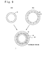
- the outer ring portion 20 and the blade 30 are integrally formed. Referring to Fig. 9 , the manufacturing method of the turbine nozzle according to the fourth embodiment will be explained.
- the first part PA and the second part PB are separately formed.
- the first part PA is a part which integrally includes the outer ring portion 20 and the blade 30 (the blades 30).
- the second part PB is the inner ring portion 10.
- the second part PB (the inner ring portion 10) is arranged inside the ring of the first part PA. That is, the first part PA and the second part PB are combined such that the outer side surface 12 of the inner ring potion 10 and the inner side surface 21 of the outer ring portion 20 are arranged to oppose each other. Then, the blade 30 of the first part PA and the second part PB are joined by "brazing".
- the method of brazing is the same as the aforementioned embodiments.
- the turbine nozzle 1 manufactured in this way has the brazed portion 40 (the joint portion formed of the brazing material) between the blade 30 and the second part PB.
Landscapes
- Engineering & Computer Science (AREA)
- Mechanical Engineering (AREA)
- General Engineering & Computer Science (AREA)
- Chemical & Material Sciences (AREA)
- Combustion & Propulsion (AREA)
- Turbine Rotor Nozzle Sealing (AREA)
Abstract
Description
- The present invention relates to a turbine nozzle and a manufacturing method thereof, and more particularly to the turbine nozzle that is a component of a turbo pump of a rocket engine and the manufacturing method thereof.
- In a rocket engine, a turbo pump is used in supplying fuel or oxidizing agent (See Patent Literature 1). As one of components of the turbo pump, there is a turbine nozzle. The turbine nozzle is the component which expands and decompresses a gas, and changes a gas flow direction such that the gas impinges a turbine blade at the optimum angle.
- Patent Literature 1: Japan Patent Application Publication
JP 2009-222010 A - Traditionally, the turbine nozzle was integrally formed as one piece. Note that if a smaller sized turbine nozzle is required, a manufacturing method thereof is limited because it is difficult to make a narrow flow passage by machining. However, if, for example, electrical discharge machining is used, there exists a problem that manufacturing costs and manufacturing time increase. If molding is used, there exist problems that the manufacturing time increases and manufacturing costs relatively becomes high for small-quantity production.
- One object of the present invention is providing a technique with which manufacturing costs and manufacturing time of a turbine nozzle can be reduced.
- In one aspect of the present invention, a manufacturing method of a turbine nozzle is provided. The turbine nozzle includes an inner ring portion, an outer ring portion having a diameter larger than a diameter of the inner ring portion, and a blade (a vane) arranged between the inner ring portion and the outer ring portion. The manufacturing method includes: (A) forming a first part which includes the blade and one of the inner ring portion and the outer ring portion integrated therein; (B) forming the other of the inner ring portion and the outer ring portion as a second part; (C) combining the first part and the second part such that an outer side surface of the inner ring portion and an inner side surface of the outer ring portion are arranged to oppose each other and that a gap is formed between the blade of the first part and the second part; and (D) flowing a brazing material in a molten state into the gap to braze the blade of the first part and the second part.
- The manufacturing method may further include: inserting a spacer in the gap between the above-mentioned step (C) and the above-mentioned step (D).
- The brazing material may be arranged at a position adjacent to the gap on an upper surface of the blade.
- The brazing material may include both a wire type brazing material and a powder type brazing material.
- Preferably, the first part includes the inner ring portion and the blade integrated therein. On the other hand, the second part is the outer ring portion.
- In another aspect of the present invention, a turbine nozzle is provided. The turbine nozzle includes: an inner ring portion; an outer ring portion having a diameter larger than a diameter of the inner ring portion; and a blade (a vane) arranged between the inner ring portion and the outer ring portion. The blade and one of the inner ring portion and the outer ring portion are integrally formed as a first part. The other of the inner ring portion and the outer ring portion constitutes a second part. The first part and the second part are joined by brazing.
- According to the present invention, it is possible to reduce the manufacturing costs and manufacturing time of the turbine nozzle.
-
-
Fig. 1 is a plan view for schematically indicating a configuration of the turbine nozzle; -
Fig. 2 is a side view for schematically indicating a cross-sectional structure of a blade of the turbine nozzle; -
Fig. 3 is a plan view for schematically indicating a manufacturing method of the turbine nozzle according to the first embodiment; -
Fig. 4 is a plan view for explaining the manufacturing method of the turbine nozzle according to the first embodiment; -
Fig. 5 is a side view for explaining the manufacturing method of the turbine nozzle according to the first embodiment; -
Fig. 6 is a plan view for explaining the manufacturing method of the turbine nozzle according to the second embodiment; -
Fig. 7 is a side view for explaining the manufacturing method of the turbine nozzle according to the second embodiment; -
Fig. 8 is a side view for explaining the manufacturing method of the turbine nozzle according to the third embodiment; and -
Fig. 9 is a plan view for schematically indicating the manufacturing method of the turbine nozzle according to the fourth embodiment. - Reference to the accompanying drawings, a turbine nozzle according to some embodiments will be explained.
-
FIG. 1 is the plan view for schematically indicating theturbine nozzle 1 according to the present embodiment. Theturbine nozzle 1 includes aninner ring portion 10, anouter ring portion 20, and a blade 30 (blades 30). - Each of the
inner ring portion 10 and theouter ring portion 20 is a member having a ring shape. Theinner ring portion 10 has aninner side surface 11 and anouter side surface 12. Theouter ring portion 20 has aninner side surface 21 and anouter side surface 22. A diameter of theouter ring portion 20 is larger than a diameter of theinner ring portion 10. More specifically, the diameter of theinner side surface 21 of theouter ring portion 20 is larger than the diameter of theouter side surface 12 of theinner ring portion 10. Thus, it is possible to place theinner ring portion 10 inside a ring of theouter ring portion 20 such that theouter side surface 12 of theinner ring portion 10 and theinner side surface 21 of theouter ring portion 20 are arranged to oppose each other. - The
blades 30 are positioned between theinner ring portion 10 and theouter ring portion 20.Fig. 2 schematically indicates the cross-sectional structure of theblades 30 when viewed along the direction A shown inFig. 1 . As shown inFig. 2 , eachblade 30 has a cross-sectional shape of a cross-sectional airfoil shape. Then, as shown inFig. 1 , a plurality ofblades 30 is arranged annularly in a space between theinner ring portion 10 and theouter ring portion 20. A gap betweenadjacent blades 30 is served as a gas flow passage. - If a more compact turbine nozzle is required, the gas flow passage also becomes narrow. When the turbine nozzle is integrally formed as a one piece, it is difficult to make precisely such a narrow gas flow passage by machining. Therefore, in the present embodiment, a new manufacturing method as shown in
Fig. 3 is proposed. - Firstly, a first part PA and a second part PB are separately formed. The first part PA is a part which integrally includes the
inner ring portion 10 and a blade 30 (blades 30). On the other hand, the second part PB is theouter ring portion 20. In forming the first part PA, it is not required to form a through hole of complex shape in order to form the gas flow passage and theblade 30 may be formed by processing a surface exposed to outside. That is, it is possible to apply a machining to form the first part PA. - Subsequently, the first part PA is arranged inside a ring of the second part PB (the outer ring portion 20). That is, the first part PA and the second part PB are combined such that the
outer side surface 12 of theinner ring portion 10 and theinner side surface 21 of theouter ring portion 20 are arranged to oppose each other. Then, theblades 30 of the first part PA and the second part PB are joined by "brazing". In this way, theturbine nozzle 1 is completed. Theturbine nozzle 1 manufactured in this way has a brazed portion 40 (a joint portion formed of a brazing material) between theblade 30 and the second part PB. -
Fig. 4 and Fig. 5 are the plan view and the side view, respectively for explaining the above-mentioned "blazing" in more detail. When the first part PA is disposed inside the ring of the second part PB (the outer ring portion 20), asmall gap 50 is formed between theblade 30 and theinner side surface 21 of the second part PB (the outer ring portion 20) as shown inFig. 4 . In other words, a size and shape of the first part PA and the second part PB is designed so that thesmall gap 50 can be formed. Although it is preferred that the gap is constant, it is not limited thereto. By melting thebrazing material 60 and flowing themolten brazing material 60 into thegap 50, theblade 30 of the first part PA and the second part PB are brazed. - The
brazing material 60 is a metal alloy having lower melting point than the first part PA and the second part PB, which are base members. For example, a nickel-basedbrazing material 60 can be used. Such abrazing material 60 is arranged in thegap 50 or the vicinity thereof. Typically, since thegap 50 is very narrow, thebrazing material 60 is placed at a position, on the upper surface of theblade 30, adjacent to thegap 50 as shown inFig. 4 and Fig. 5 . After the arrangement of thebrazing material 60, heating is performed. By the heating, thebrazing material 60 is molten, and the molten brazing material flows into thegap 50. In this way, theblade 30 of the first part PA and the second part PB are brazed. - As explained above, according to the present embodiment, the
turbine nozzle 1 is manufactured by brazing the first part PA and the second part PB. In the case in which the turbine nozzle is downsized, the gas passage also becomes narrow. In the case in which theturbine nozzle 1 is integrally formed as the one piece, it is difficult to make precisely such a narrow gas flow passage by machining. On the other hand, according to the present embodiment, the first part PA and the second part PB can be easily made by machining. Therefore, as compared with the case of electrical discharge machining or casting, it is possible to reduce the costs and time for manufacturing theturbine nozzle 1. -
Fig. 6 and Fig. 7 are the plan view and the side view, respectively for explaining the blazing according to the second embodiment. As described above, when the first part PA is disposed inside the ring of the second part PB, thesmall gap 50 is formed. Therefore, after brazing, "misalignment" between the first part PA and the second part PB is likely to occur. To prevent the occurrence of such misalignment, a spacer 70 (spacers 70) is inserted into thegap 50 according to the second embodiment. After the insertion of thespacer 70 into thegap 50, as in the first embodiment, thebrazing material 60 is molten and the molten brazing material is flown into thegap 50. - As the
spacer 70, a nickel foil can be exemplified. Such aspacer 70 is arranged between the outer side surface of theblade 30 and theinner side surface 21 of theouter ring portion 20. Installation position of thespacer 70 is arbitrary so long as the occurrence of the misalignment can be prevented. However, it is preferable that thespacers 70 are evenly spaced over the entire circumference of thegap 50. - According to the second embodiment, the same effect as the first embodiment can be obtained. In addition, the "misalignment" between the first part PA and the second part PB is prevented from occurring.
-
Fig. 8 is the schematic diagram for explaining thebrazing material 60 according to the third embodiment. In the third embodiment, thebrazing material 60 includes a powdertype brazing material 62 in addition to a wiretype brazing material 61. The powdertype brazing material 62 has characteristics of being easily molten than the wiretype brazing material 61. Then, when the powdertype brazing material 62 melts, it induces melting of the wire type brazing material and the wiretype brazing material 61 starts melting. That is, when the powdertype brazing material 62 is used, the wiretype brazing material 61 is likely to easily melt as compared with the case where there is no powdertype brazing material 62. - The powdered
type brazing material 62 is, for example, provided in an end portion of thebrazing material 60. In the example shown inFig. 8 , the powdertype brazing material 62 is applied on both ends of the wiretype brazing material 61. Thereby, thebrazing material 60 is likely to easily melt as a whole. - The combination of the second embodiment and the third embodiment described above is possible.
- In the embodiments described above, the
inner ring portion 10 and theblade 30 are integrally formed. In the fourth embodiment, alternatively, theouter ring portion 20 and theblade 30 are integrally formed. Referring toFig. 9 , the manufacturing method of the turbine nozzle according to the fourth embodiment will be explained. - Firstly, the first part PA and the second part PB are separately formed. In the present embodiment, the first part PA is a part which integrally includes the
outer ring portion 20 and the blade 30 (the blades 30). On the other hand, the second part PB is theinner ring portion 10. - Subsequently, the second part PB (the inner ring portion 10) is arranged inside the ring of the first part PA. That is, the first part PA and the second part PB are combined such that the
outer side surface 12 of theinner ring potion 10 and theinner side surface 21 of theouter ring portion 20 are arranged to oppose each other. Then, theblade 30 of the first part PA and the second part PB are joined by "brazing". The method of brazing is the same as the aforementioned embodiments. Theturbine nozzle 1 manufactured in this way has the brazed portion 40 (the joint portion formed of the brazing material) between theblade 30 and the second part PB. - However, it is easier to form the
blade 30 on theouter side surface 12 of theinner ring portion 10 as compared with the case where theblade 30 is formed on theinner side surface 21 of theouter ring portion 20. In this sense, those of the aforementioned embodiments is preferred than those of the fourth embodiment. - In the above, some embodiments of the present invention have been explained with reference to the attached drawings. However, the present invention is not limited to the above-mentioned embodiments, and they may be appropriately modified by those skilled in the art without departing from the spirit or scope of the general invention concept thereof.
- This application claims a priority based on Japanese Patent Application No.
JP 2013-029430
Claims (6)
- A manufacturing method of a turbine nozzle, the turbine nozzle including an inner ring portion, an outer ring portion having a diameter larger than a diameter of the inner ring portion and a blade arranged between the inner ring portion and the outer ring portion, the method comprising:(A) forming a first part which includes the blade and one of the inner ring portion and the outer ring portion integrated therein;(B) forming the other of the inner ring portion and the outer ring portion as a second part;(C) combining the first part and the second part such that an outer side surface of the inner ring portion and an inner side surface of the outer ring portion are arranged to oppose each other and that a gap is formed between the blade of the first part and the second part; and(D) flowing a brazing material in a molten state into the gap to braze the blade of the first part and the second part.
- The manufacturing method according to claim 1, further comprising:inserting a spacer in the gap between (C) the combining the first part and the second part and (D) the flowing a brazing material in a molten state into the gap.
- The manufacturing method according to claim 1 or 2, wherein the brazing material is arranged at a position adjacent to the gap on an upper surface of the blade.
- The manufacturing method according to any one of claims 1 to 3, wherein the brazing material includes both a wire type brazing material and a powder type brazing material.
- The manufacturing method according to any one of claims 1 to 4, wherein the first part includes the inner ring portion and the blade integrated therein,
wherein the second part is the outer ring portion. - A turbine nozzle comprising:an inner ring portion;an outer ring portion having a diameter larger than a diameter of the inner ring portion; anda blade arranged between the inner ring portion and the outer ring portion,wherein the blade and one of the inner ring portion and the outer ring portion are integrally formed as a first part,wherein the other of the inner ring portion and the outer ring portion constitutes a second part, andwherein the first part and the second part are joined by brazing.
Applications Claiming Priority (2)
| Application Number | Priority Date | Filing Date | Title |
|---|---|---|---|
| JP2013029430A JP6045389B2 (en) | 2013-02-18 | 2013-02-18 | Turbine nozzle and manufacturing method thereof |
| PCT/JP2014/053603 WO2014126234A1 (en) | 2013-02-18 | 2014-02-17 | Turbine nozzle and method for manufacturing same |
Publications (2)
| Publication Number | Publication Date |
|---|---|
| EP2933440A1 true EP2933440A1 (en) | 2015-10-21 |
| EP2933440A4 EP2933440A4 (en) | 2016-03-30 |
Family
ID=51354232
Family Applications (1)
| Application Number | Title | Priority Date | Filing Date |
|---|---|---|---|
| EP14751725.4A Withdrawn EP2933440A4 (en) | 2013-02-18 | 2014-02-17 | Turbine nozzle and method for manufacturing same |
Country Status (6)
| Country | Link |
|---|---|
| US (1) | US20150354593A1 (en) |
| EP (1) | EP2933440A4 (en) |
| JP (1) | JP6045389B2 (en) |
| CN (1) | CN104937220B (en) |
| RU (1) | RU2015128612A (en) |
| WO (1) | WO2014126234A1 (en) |
Families Citing this family (4)
| Publication number | Priority date | Publication date | Assignee | Title |
|---|---|---|---|---|
| WO2019167319A1 (en) | 2018-02-27 | 2019-09-06 | 株式会社Ihi | Rocket-engine turbo pump |
| CN115523029B (en) * | 2022-10-24 | 2024-12-10 | 德阳钰鑫机械制造有限公司 | A manufacturing process of rectifier and rectifier |
| CN117324710A (en) * | 2023-09-18 | 2024-01-02 | 陕西航天动力高科技股份有限公司 | Sheet metal type hydraulic torque converter brazing method |
| CN119589139B (en) * | 2024-11-05 | 2025-12-12 | 中国航发南方工业有限公司 | Size control method for vacuum brazing of cantilever structure stator assembly |
Family Cites Families (22)
| Publication number | Priority date | Publication date | Assignee | Title |
|---|---|---|---|---|
| US2143466A (en) * | 1937-12-31 | 1939-01-10 | Westinghouse Electric & Mfg Co | Turbine apparatus |
| US2611161A (en) * | 1949-03-17 | 1952-09-23 | Caterpillar Tractor Co | Pattern fixture for making molds for turbines |
| JPS5812441B2 (en) * | 1979-04-17 | 1983-03-08 | 三井造船株式会社 | Turbine nozzle manufacturing method |
| US4464094A (en) * | 1979-05-04 | 1984-08-07 | Trw Inc. | Turbine engine component and method of making the same |
| JPS5741405A (en) * | 1980-08-22 | 1982-03-08 | Hitachi Ltd | Manufacturing method of turbine stator |
| JPH05202701A (en) * | 1992-01-28 | 1993-08-10 | Mitsubishi Heavy Ind Ltd | Joining method |
| US5332360A (en) * | 1993-09-08 | 1994-07-26 | General Electric Company | Stator vane having reinforced braze joint |
| US6935555B2 (en) * | 2000-04-28 | 2005-08-30 | Elliott Turbomachinery Co., Inc. | Method of brazing and article made therefrom |
| SE523075C2 (en) * | 2001-11-22 | 2004-03-23 | Volvo Aero Corp | Process for producing a stator or rotor component |
| US6969240B2 (en) * | 2003-08-01 | 2005-11-29 | Honeywell International Inc. | Integral turbine composed of a cast single crystal blade ring diffusion bonded to a high strength disk |
| JP2005098133A (en) * | 2003-09-22 | 2005-04-14 | Toshiba Corp | Diffusion brazing repair method and repair jig for gas turbine blades |
| US20050067061A1 (en) * | 2003-09-26 | 2005-03-31 | General Electric Company | Nickel-based braze alloy compositions and related processes and articles |
| US7341427B2 (en) * | 2005-12-20 | 2008-03-11 | General Electric Company | Gas turbine nozzle segment and process therefor |
| US7628586B2 (en) * | 2005-12-28 | 2009-12-08 | Elliott Company | Impeller |
| CN101215977A (en) * | 2007-12-29 | 2008-07-09 | 东方电气集团东方汽轮机有限公司 | Steam Turbine Nozzle Group and Its Processing Technology |
| JP4672747B2 (en) | 2008-03-18 | 2011-04-20 | 三菱重工業株式会社 | Rocket nozzle and rocket engine combustion gas flow control method |
| JP2010127280A (en) * | 2008-11-25 | 2010-06-10 | General Electric Co <Ge> | Vane with reduced stress |
| JP4699531B2 (en) * | 2009-01-27 | 2011-06-15 | 三菱重工業株式会社 | Impeller manufacturing method and impeller |
| CN201574784U (en) * | 2009-12-31 | 2010-09-08 | 山东齐鲁电机制造有限公司 | High-pressure steam-admission spray nozzle set of integrally milled steam turbine |
| JP5535878B2 (en) * | 2010-11-11 | 2014-07-02 | 三菱重工業株式会社 | Impeller manufacturing method |
| US9447689B2 (en) * | 2011-06-17 | 2016-09-20 | General Electric Company | Method of repairing a turbine nozzle segment in a turbine engine |
| JP2013029430A (en) | 2011-07-28 | 2013-02-07 | Mitsubishi Electric Corp | Two-channel tracking device and tracking method |
-
2013
- 2013-02-18 JP JP2013029430A patent/JP6045389B2/en not_active Expired - Fee Related
-
2014
- 2014-02-17 CN CN201480005178.3A patent/CN104937220B/en not_active Expired - Fee Related
- 2014-02-17 US US14/760,517 patent/US20150354593A1/en not_active Abandoned
- 2014-02-17 RU RU2015128612A patent/RU2015128612A/en not_active Application Discontinuation
- 2014-02-17 WO PCT/JP2014/053603 patent/WO2014126234A1/en not_active Ceased
- 2014-02-17 EP EP14751725.4A patent/EP2933440A4/en not_active Withdrawn
Also Published As
| Publication number | Publication date |
|---|---|
| JP6045389B2 (en) | 2016-12-14 |
| JP2014156851A (en) | 2014-08-28 |
| EP2933440A4 (en) | 2016-03-30 |
| RU2015128612A (en) | 2017-03-23 |
| CN104937220A (en) | 2015-09-23 |
| WO2014126234A1 (en) | 2014-08-21 |
| US20150354593A1 (en) | 2015-12-10 |
| CN104937220B (en) | 2016-11-09 |
Similar Documents
| Publication | Publication Date | Title |
|---|---|---|
| US10465540B2 (en) | Airfoil assembly with spacer and tie-spar | |
| CN101839199B (en) | The method and apparatus that sacrificial shield for fuel injector is provided | |
| US12000339B2 (en) | Integral superstructure for load path optimization | |
| EP3061918B1 (en) | Tapered gas turbine segment seals | |
| US10280775B2 (en) | Guide vane ring for a turbomachine | |
| EP2716396B1 (en) | Hollow curved plate, method for manufacturing same, and burner for gas turbine | |
| US10119405B2 (en) | Cooling circuit for a multi-wall blade | |
| EP3336311B1 (en) | Turbomachine blade with trailing edge cooling circuit | |
| EP3184737B1 (en) | Multi-wall blade with cooling circuit | |
| US9926788B2 (en) | Cooling circuit for a multi-wall blade | |
| EP3184740A1 (en) | Cooling circuit for a multi-wall blade | |
| EP2818664A1 (en) | Turbo charger | |
| US9556795B2 (en) | Integrated heat shield | |
| US20170022829A1 (en) | Nozzle guide vane with composite heat shields | |
| US10619596B2 (en) | Gas turbine engine exhaust ejector/mixer | |
| US20150354593A1 (en) | Turbine nozzle and manufacturing method thereof | |
| JP6924021B2 (en) | Platform core supply for multi-wall blades | |
| CN105452609B (en) | The manufacture method of the high-temperature component of combustion gas turbine, the combustion gas turbine for possessing this high-temperature component and combustion gas turbine high-temperature component | |
| CN103375817A (en) | fuel nozzle | |
| JP2019002397A (en) | Turbomachine cooling system | |
| JP2015034547A (en) | System and method for reducing or suppressing one or more flows between a hot gas flow path and a turbine wheel space | |
| JP5088196B2 (en) | Turbine nozzle segment | |
| JP2016121679A (en) | Gas turbine transition piece aft frame assembly supports | |
| US11174753B2 (en) | Guide vane for a turbomachine |
Legal Events
| Date | Code | Title | Description |
|---|---|---|---|
| PUAI | Public reference made under article 153(3) epc to a published international application that has entered the european phase |
Free format text: ORIGINAL CODE: 0009012 |
|
| 17P | Request for examination filed |
Effective date: 20150716 |
|
| AK | Designated contracting states |
Kind code of ref document: A1 Designated state(s): AL AT BE BG CH CY CZ DE DK EE ES FI FR GB GR HR HU IE IS IT LI LT LU LV MC MK MT NL NO PL PT RO RS SE SI SK SM TR |
|
| AX | Request for extension of the european patent |
Extension state: BA ME |
|
| A4 | Supplementary search report drawn up and despatched |
Effective date: 20160226 |
|
| RIC1 | Information provided on ipc code assigned before grant |
Ipc: F01D 25/00 20060101ALI20160222BHEP Ipc: F01D 25/24 20060101AFI20160222BHEP |
|
| DAX | Request for extension of the european patent (deleted) | ||
| GRAP | Despatch of communication of intention to grant a patent |
Free format text: ORIGINAL CODE: EPIDOSNIGR1 |
|
| INTG | Intention to grant announced |
Effective date: 20170628 |
|
| STAA | Information on the status of an ep patent application or granted ep patent |
Free format text: STATUS: THE APPLICATION IS DEEMED TO BE WITHDRAWN |
|
| 18D | Application deemed to be withdrawn |
Effective date: 20171109 |