EP2933344A1 - Heat treatment equipment line for seamless steel pipe, and method for manufacturing high-strength stainless steel pipe - Google Patents
Heat treatment equipment line for seamless steel pipe, and method for manufacturing high-strength stainless steel pipe Download PDFInfo
- Publication number
- EP2933344A1 EP2933344A1 EP13862381.4A EP13862381A EP2933344A1 EP 2933344 A1 EP2933344 A1 EP 2933344A1 EP 13862381 A EP13862381 A EP 13862381A EP 2933344 A1 EP2933344 A1 EP 2933344A1
- Authority
- EP
- European Patent Office
- Prior art keywords
- pipe
- steel tube
- less
- temperature
- cooling
- Prior art date
- Legal status (The legal status is an assumption and is not a legal conclusion. Google has not performed a legal analysis and makes no representation as to the accuracy of the status listed.)
- Granted
Links
Images
Classifications
-
- C—CHEMISTRY; METALLURGY
- C21—METALLURGY OF IRON
- C21D—MODIFYING THE PHYSICAL STRUCTURE OF FERROUS METALS; GENERAL DEVICES FOR HEAT TREATMENT OF FERROUS OR NON-FERROUS METALS OR ALLOYS; MAKING METAL MALLEABLE, e.g. BY DECARBURISATION OR TEMPERING
- C21D9/00—Heat treatment, e.g. annealing, hardening, quenching or tempering, adapted for particular articles; Furnaces therefor
- C21D9/08—Heat treatment, e.g. annealing, hardening, quenching or tempering, adapted for particular articles; Furnaces therefor for tubular bodies or pipes
- C21D9/085—Cooling or quenching
-
- C—CHEMISTRY; METALLURGY
- C21—METALLURGY OF IRON
- C21D—MODIFYING THE PHYSICAL STRUCTURE OF FERROUS METALS; GENERAL DEVICES FOR HEAT TREATMENT OF FERROUS OR NON-FERROUS METALS OR ALLOYS; MAKING METAL MALLEABLE, e.g. BY DECARBURISATION OR TEMPERING
- C21D1/00—General methods or devices for heat treatment, e.g. annealing, hardening, quenching or tempering
- C21D1/18—Hardening; Quenching with or without subsequent tempering
- C21D1/25—Hardening, combined with annealing between 300 degrees Celsius and 600 degrees Celsius, i.e. heat refining ("Vergüten")
-
- C—CHEMISTRY; METALLURGY
- C21—METALLURGY OF IRON
- C21D—MODIFYING THE PHYSICAL STRUCTURE OF FERROUS METALS; GENERAL DEVICES FOR HEAT TREATMENT OF FERROUS OR NON-FERROUS METALS OR ALLOYS; MAKING METAL MALLEABLE, e.g. BY DECARBURISATION OR TEMPERING
- C21D9/00—Heat treatment, e.g. annealing, hardening, quenching or tempering, adapted for particular articles; Furnaces therefor
- C21D9/0062—Heat-treating apparatus with a cooling or quenching zone
-
- C—CHEMISTRY; METALLURGY
- C21—METALLURGY OF IRON
- C21D—MODIFYING THE PHYSICAL STRUCTURE OF FERROUS METALS; GENERAL DEVICES FOR HEAT TREATMENT OF FERROUS OR NON-FERROUS METALS OR ALLOYS; MAKING METAL MALLEABLE, e.g. BY DECARBURISATION OR TEMPERING
- C21D9/00—Heat treatment, e.g. annealing, hardening, quenching or tempering, adapted for particular articles; Furnaces therefor
- C21D9/08—Heat treatment, e.g. annealing, hardening, quenching or tempering, adapted for particular articles; Furnaces therefor for tubular bodies or pipes
-
- C—CHEMISTRY; METALLURGY
- C22—METALLURGY; FERROUS OR NON-FERROUS ALLOYS; TREATMENT OF ALLOYS OR NON-FERROUS METALS
- C22C—ALLOYS
- C22C38/00—Ferrous alloys, e.g. steel alloys
- C22C38/001—Ferrous alloys, e.g. steel alloys containing N
-
- C—CHEMISTRY; METALLURGY
- C22—METALLURGY; FERROUS OR NON-FERROUS ALLOYS; TREATMENT OF ALLOYS OR NON-FERROUS METALS
- C22C—ALLOYS
- C22C38/00—Ferrous alloys, e.g. steel alloys
- C22C38/002—Ferrous alloys, e.g. steel alloys containing In, Mg, or other elements not provided for in one single group C22C38/001 - C22C38/60
-
- C—CHEMISTRY; METALLURGY
- C22—METALLURGY; FERROUS OR NON-FERROUS ALLOYS; TREATMENT OF ALLOYS OR NON-FERROUS METALS
- C22C—ALLOYS
- C22C38/00—Ferrous alloys, e.g. steel alloys
- C22C38/005—Ferrous alloys, e.g. steel alloys containing rare earths, i.e. Sc, Y, Lanthanides
-
- C—CHEMISTRY; METALLURGY
- C22—METALLURGY; FERROUS OR NON-FERROUS ALLOYS; TREATMENT OF ALLOYS OR NON-FERROUS METALS
- C22C—ALLOYS
- C22C38/00—Ferrous alloys, e.g. steel alloys
- C22C38/02—Ferrous alloys, e.g. steel alloys containing silicon
-
- C—CHEMISTRY; METALLURGY
- C22—METALLURGY; FERROUS OR NON-FERROUS ALLOYS; TREATMENT OF ALLOYS OR NON-FERROUS METALS
- C22C—ALLOYS
- C22C38/00—Ferrous alloys, e.g. steel alloys
- C22C38/04—Ferrous alloys, e.g. steel alloys containing manganese
-
- C—CHEMISTRY; METALLURGY
- C22—METALLURGY; FERROUS OR NON-FERROUS ALLOYS; TREATMENT OF ALLOYS OR NON-FERROUS METALS
- C22C—ALLOYS
- C22C38/00—Ferrous alloys, e.g. steel alloys
- C22C38/06—Ferrous alloys, e.g. steel alloys containing aluminium
-
- C—CHEMISTRY; METALLURGY
- C22—METALLURGY; FERROUS OR NON-FERROUS ALLOYS; TREATMENT OF ALLOYS OR NON-FERROUS METALS
- C22C—ALLOYS
- C22C38/00—Ferrous alloys, e.g. steel alloys
- C22C38/18—Ferrous alloys, e.g. steel alloys containing chromium
- C22C38/24—Ferrous alloys, e.g. steel alloys containing chromium with vanadium
-
- C—CHEMISTRY; METALLURGY
- C22—METALLURGY; FERROUS OR NON-FERROUS ALLOYS; TREATMENT OF ALLOYS OR NON-FERROUS METALS
- C22C—ALLOYS
- C22C38/00—Ferrous alloys, e.g. steel alloys
- C22C38/18—Ferrous alloys, e.g. steel alloys containing chromium
- C22C38/40—Ferrous alloys, e.g. steel alloys containing chromium with nickel
-
- C—CHEMISTRY; METALLURGY
- C22—METALLURGY; FERROUS OR NON-FERROUS ALLOYS; TREATMENT OF ALLOYS OR NON-FERROUS METALS
- C22C—ALLOYS
- C22C38/00—Ferrous alloys, e.g. steel alloys
- C22C38/18—Ferrous alloys, e.g. steel alloys containing chromium
- C22C38/40—Ferrous alloys, e.g. steel alloys containing chromium with nickel
- C22C38/42—Ferrous alloys, e.g. steel alloys containing chromium with nickel with copper
-
- C—CHEMISTRY; METALLURGY
- C22—METALLURGY; FERROUS OR NON-FERROUS ALLOYS; TREATMENT OF ALLOYS OR NON-FERROUS METALS
- C22C—ALLOYS
- C22C38/00—Ferrous alloys, e.g. steel alloys
- C22C38/18—Ferrous alloys, e.g. steel alloys containing chromium
- C22C38/40—Ferrous alloys, e.g. steel alloys containing chromium with nickel
- C22C38/44—Ferrous alloys, e.g. steel alloys containing chromium with nickel with molybdenum or tungsten
-
- C—CHEMISTRY; METALLURGY
- C22—METALLURGY; FERROUS OR NON-FERROUS ALLOYS; TREATMENT OF ALLOYS OR NON-FERROUS METALS
- C22C—ALLOYS
- C22C38/00—Ferrous alloys, e.g. steel alloys
- C22C38/18—Ferrous alloys, e.g. steel alloys containing chromium
- C22C38/40—Ferrous alloys, e.g. steel alloys containing chromium with nickel
- C22C38/46—Ferrous alloys, e.g. steel alloys containing chromium with nickel with vanadium
-
- C—CHEMISTRY; METALLURGY
- C22—METALLURGY; FERROUS OR NON-FERROUS ALLOYS; TREATMENT OF ALLOYS OR NON-FERROUS METALS
- C22C—ALLOYS
- C22C38/00—Ferrous alloys, e.g. steel alloys
- C22C38/18—Ferrous alloys, e.g. steel alloys containing chromium
- C22C38/40—Ferrous alloys, e.g. steel alloys containing chromium with nickel
- C22C38/48—Ferrous alloys, e.g. steel alloys containing chromium with nickel with niobium or tantalum
-
- C—CHEMISTRY; METALLURGY
- C22—METALLURGY; FERROUS OR NON-FERROUS ALLOYS; TREATMENT OF ALLOYS OR NON-FERROUS METALS
- C22C—ALLOYS
- C22C38/00—Ferrous alloys, e.g. steel alloys
- C22C38/18—Ferrous alloys, e.g. steel alloys containing chromium
- C22C38/40—Ferrous alloys, e.g. steel alloys containing chromium with nickel
- C22C38/50—Ferrous alloys, e.g. steel alloys containing chromium with nickel with titanium or zirconium
-
- C—CHEMISTRY; METALLURGY
- C22—METALLURGY; FERROUS OR NON-FERROUS ALLOYS; TREATMENT OF ALLOYS OR NON-FERROUS METALS
- C22C—ALLOYS
- C22C38/00—Ferrous alloys, e.g. steel alloys
- C22C38/18—Ferrous alloys, e.g. steel alloys containing chromium
- C22C38/40—Ferrous alloys, e.g. steel alloys containing chromium with nickel
- C22C38/58—Ferrous alloys, e.g. steel alloys containing chromium with nickel with more than 1.5% by weight of manganese
Definitions
- the present invention relates to a method for manufacturing a high strength stainless steel tube or pipe and a heat treatment equipment line for a high strength stainless steel tube or pipe in order to give stable product quality to a high Cr seamless steel tube or pipe which is subjected to a quenching and tempering treatment.
- heat treatments such as quenching, tempering, annealing, and a solution heat treatment are used as heat treatments for a steel tube or pipe. These heat treatments are being performed selectively in accordance with a purpose such as performance required by customers or homogenization of product quality.
- Patent Literature 1 a heat treatment equipment line in which a heating furnace for quenching, equipment for quenching, and a tempering furnace are effectively arranged is proposed in order to increaseenhance efficiency and compactness.
- the martensite transformation finish temperature is about room temperature or equal to or lower than room temperature (25°C).
- room temperature 25°C.
- a quenching and tempering treatment is performed on this high strength stainless steel tube or pipe using conventional heat treatment equipment, since a cooling stop temperature after quenching varies due to a change in room temperature and constraints because of processes in a continuous operation, there is a variation in the volume fraction of a residual austenite phase before tempering is performed. Therefore, there is a problem in that, since mechanical properties such as strength and toughness become unstable after a heat treatment has been performed, these mechanical properties vary among products.
- An object of the present invention is, by solving the problems described above, to provide a heat treatment equipment line for a seamless steel tube or pipe, and a method for manufacturing a high strength stainless steel tube or pipe with which stable product quality can be obtained after a heat treatment has been performed, and the subject matter of the present invention is as follows.
- a cooling stop temperature in a quenching treatment becomes 20°C or lower, or preferably 10°C or lower, and definite. Therefore, since the volume fraction of a residual austenite phase becomes definite before a tempering treatment is performed even when a high strength stainless steel tube or pipe which contains 14% or more of Cr and which contains alloy chemical elements such as Ni and Mo is manufactured, stable product quality can be obtained.
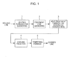
- Fig. 1 is a schematic diagram illustrating one example of the heat treatment equipment line for a seamless steel tube or pipe according to the present invention.
- a cooling stop temperature after quenching has been performed is, for example, 100°C or lower or equal to room temperature as described, for example, in Patent Literature 2.
- Fig. 1 invented a heat treatment equipment line in which a cooling facilities 4 which is capable of always cooling a heat treated steel tube or pipe to a definite temperature (20°C or lower, or preferably 10°C or lower) using water as a cooling medium is arranged between equipment for quenching 2 and a tempering furnace 5.
- the cooling facilities 4, which are arranged at the end on the downstream side of a heat treatment carrier line 3 in Fig. 1 may be arranged in the middle of the heat treatment carrier line 3 or at the end on the upstream side of the heat treatment carrier line 3.
- the water which has been used as a cooling medium circulates between the cooling facilities 4 and a refrigerator for a cooling medium (not illustrated) while the temperature of the water is continuously detected.
- the circulating water always has a definite temperature by being cooled by the refrigerator for a cooling medium.
- “always definite” refers to a case where the temperature of the cooling medium is always definite when the cooling medium is fed into the cooling facilities 4 from the refrigerator for a cooling medium.
- definite refers to a case where a temperature is within a range of a specified temperature ⁇ 3.0°C.
- C is an important chemical element which is relevant to the corrosion resistance and strength of martensite stainless steel.
- the C content be 0.005% or more.
- the C content be in a range of 0.005% or more and 0.05% or less in the present invention.
- the C content be as small as possible from the viewpoint of corrosion resistance.
- the C content be large in order to achieve sufficient strength. In consideration of the balance between both properties, it is more preferable that the C content be 0.005% or more and 0.03% or less.
- Si 0.05% or more and 1.0% or less
- Si is a chemical element which functions as a deoxidizing agent.
- the Si content be 0.05% or more.
- the Si content be in a range of 0.05% or more and 1.0% or less, or more preferably 0.10% or more and 0.3% or less.
- Mn 0.2% or more and 1.8% or less
- Mn is a chemical element which increases strength. It is preferable that the Mn content be 0.2% or more in order to achieve the desired strength according to the present invention. In the case where the Mn content is more than 1.8%, there may be a negative effect on toughness. Therefore, it is preferable that the Mn content be 0.2% or more and 1.8% or less, or more preferably 0.2% or more and 0.8% or less.
- P is a chemical element which decreasedeteriorates both corrosion resistance and sulfide stress corrosion cracking resistance. It is preferable that the P content be as small as possible in the present invention. However, an excessive decrease in P content causes an increase in manufacturing cost. In order to prevent a decreasedeterioration in both corrosion resistance and sulfide stress corrosion cracking resistance within a range industrially realizable at comparatively low cost, it is preferable that the P content be 0.03% or less, or more preferably 0.02% or less.
- S is a chemical element which significantly decreasedeteriorates hot workability in a pipe manufacturing process. It is preferable that the S content be as small as possible. Since it is possible to manufacture a steel tube or pipe using a common process in the case where the S content is decreased to 0.005% or less, it is preferable that the S content be 0.005% or less, or more preferably 0.002% or less.
- Cr is a chemical element which increaseenhances corrosion resistance by forming a protective surface film on a steel tube or pipe and which, in particular, contributes to an increaseenhance in CO 2 corrosion resistance and sulfide stress corrosion cracking resistance. It is preferable that the Cr content be 14% or more from the viewpoint of corrosion resistance. Since there is an excessive increase in the volume fractions of an austenite phase and a ferrite phase in the case where the Cr content is more than 20%, the desired high strength cannot be achieved, and there is a decreasedeterioration in toughness and hot workability. It is more preferable that the Cr content be 15% or more and 18% or less.
- Ni has a function for increasingenhanceing CO 2 corrosion resistance, pitting corrosion resistance, and sulfide stress corrosion cracking resistance by strengthening a protective surface film. Moreover, Ni is a chemical element which increases the strength of steel through solid solution strengthening. Such effects are recognized in the case where the Ni content is 1.5% or more. However, in the case where the Ni content is more than 10%, the desired high strength cannot be achieved, and there may also be a decreasedeterioration in hot workability. It is more preferable that the Ni content be 3% or more and 8% or less.
- Mo is a chemical element which increaseenhances resistance to pitting corrosion caused by Cl - . It is preferable that the Mo content be 1% or more in the present invention. In the case where the Mo content is more than 5%, since there is an excessive increase in the amounts of an austenite phase and a ferrite phase, the desired high strength cannot be achieved, and there may also be a decreasedeterioration in toughness and hot workability. In addition, in the case where the Mo content is more than 5%, since intermetallics are precipitated, there may be a decreasedeterioration in toughness and sulfide stress corrosion cracking resistance. It is more preferable that the Mo content be 2% or more and 4% or less.
- N is a chemical element which significantly increaseenhances pitting corrosion resistance.
- the N content is more than 0.15%, since various kinds of nitrides are formed, there may be a decreasedeterioration in toughness due to the formation of such nitrides. Therefore, it is preferable that the Ni content be 0.15% or less, or more preferably 0.1% or less.
- the O content has a negative effect on various properties as a result of being present in the form of oxides in steel. It is preferable that the O content be as small as possible in order to improve the properties. In particular, in the case where the O content is more than 0.006%, there is a significant decreasedeterioration in hot workability, corrosion resistance, sulfide stress corrosion cracking resistance, and toughness. Therefore, in the present invention, it is preferable that the O content be 0.006% or less.
- one or more selected from among Al: 0.002% or more and 0.05% or less, Cu: 3.5% or less, Nb: 0.5% or less, V; 0.5% or less, Ti: 0.3% or less, Zr: 0.2% or less, W: 3% or less, B: 0.01% or less, Ca: 0.01% or less, and REM: 0.1% or less may be further added.
- Al is a chemical element which has strong deoxidizingaction. It is preferable that the Al content be 0.002% or more in order to realize this effect. In the case where the Al content is more than 0.05%, there may be a negative effect on toughness. Therefore, in the case where Al is added, it is preferable that the Al content be in a range of 0.002% or more and 0.05% or less, or more preferably 0.03% or less. Here, in the case where Al is not added, Al may be contained in an amount of less than about 0.002% as an inevitable impurity. There is the advantage that there is a significant increaseenhancement in low-temperature toughness in the case where the Al content is less than about 0.002%.
- Cu is a chemical element which increaseenhances sulfide stress corrosion cracking resistance by preventing hydrogen from intruding into steel as a result of strengthening a protective surface film. This effect becomes noticeable in the case where the Cu content is 0.5% or more.
- the Cu content is more than 3.5%, since CuS is precipitated in grain boundary, there is a decreasedeterioration in hot workability. Therefore, it is preferable that the Cu content be 3.5% or less. It is more preferable that the Cu content be 1.0% or more and 3.0% or less.
- Nb, V, Ti, Zr, W, and B are all chemical elements which increase strength, and these chemical elements are added as needed. Also, V, Ti, Zr, W, and B are chemical elements which improve stress corrosion cracking resistance. Such effects become noticeable in the case where the Nb content is 0.03% or more, the V content is 0.02% or more, the Ti content is 0.03% or more, the Zr content is 0.03% or more, the W content is 0.2% or more or the B content is 0.0005% or more.
- the Nb content is more than 0.5%, the V content is more than 0.5%, the Ti content is more than 0.3%, the Zr content is more than 0.2%, the W content is more than 3% or the B content is more than 0.01%. Therefore, it is preferable that the Nb content be 0.5% or less, the V content be 0.5% or less, the Ti content be 0.3% or less, the Zr content be 0.2% or less, the W content be 3% or less, and the B content be 0.01 or less.
- Ca has a function for spheroidizing sulfide-based inclusions by fixing S in the form of CaS. With this function, the hydrogen trapping ability of inclusions is decreasedeteriorated by decreasing the lattice strain of a matrix surrounding the inclusions. Such an effect is noticeable in the case where the Ca content is 0.0005% or more. In addition, in the case where the Ca content is more than 0.01%, since there is an increase in the amount of CaO, there is a decreasedeterioration in corrosion resistance. Therefore, it is preferable that the Ca content be in a range of 0.01% or less.
- REM increaseenhances stress corrosion cracking resistance in an environment of an aqueous chloride solution having a high temperature. Such an effect becomes noticeable in the case where the REM content is 0.001% or more. On the other hand, in the case where the REM content is excessively large, the effect becomes saturated. Therefore, it is preferable that the upper limit of the REM content be 0.1%. It is more preferable that the REM content be 0.001% or more and 0.01% or less.
- "REM” according to the present invention refers to yttrium (Y) having an atomic number of 39 and lanthanoid elements having an atomic number of 57 (lanthanum (La)) to 71 (lutetium (Lu)). It is preferable that the stainless steel according to the present invention contain one, or more of the REM mentioned above.
- the REM content refers to the total content of one, or more selected from among the plural kinds of REM mentioned above.
- the remainder of the chemical composition other than chemical constituents described above consists of Fe and inevitable impurities.
- molten steel having the chemical composition described above be manufactured using a commonly well-known manufacturing method such as one using a steel converter furnace, an electric furnace, or a vacuum melting furnace, and that the molten steel be made into a steel tube or pipe material such as a billet using a commonly well-known method such as a continuous casting method or a slabbing mill method for rolling an ingot.
- a commonly well-known method such as a continuous casting method or a slabbing mill method for rolling an ingot.
- such a steel tube or pipe material is made into a seamless steel tube or pipe having a desired size by heating the steel tube or pipe material, by performing hot rolling on the heated material and forming it into a tube or pipe in a manufacturing process using a common Mannesmannplug mill method or a Mannesmann-mandrel mill method.
- the seamless steel tube or pipe be cooled to room temperature at a cooling rate more than that of air cooling.
- a seamless steel tube or pipe may be manufactured by performing hot extrusion using a press method.
- the hot rolling or hot extrusion mentioned above corresponds to a treatment in the rolling line in Fig. 1 .
- the seamless steel tube or pipe described above is heated again at a temperature of 850°C or higher and 1100°C or lower using a heating furnace for quenching 1. Then, the heated steel tube or pipe is cooled to a temperature of 50°C or lower at a cooling rate equal to or more than that of air cooling using equipment for quenching 2.
- the seamless steel tube or pipe which has been cooled using the equipment for quenching 2 runs through a heat treatment carrier line 3 (even if the temperature of the seamless steel tube or pipe which has been cooled using the equipment for quenching 2 is higher than 50°C, it is appropriate that the steel tube or pipe be cooled to a temperature of 50°C or lower as a result of running through the heat treatment carrier line 3). Further, the seamless steel tube or pipe is cooled to a temperature of 20°C or lower using the cooling facilities 4 which are arranged at the end on the downstream side of the heat treatment carrier line 3. As described above, it is preferable that a quenching treatment be performed using the heating furnace for quenching 1 through to the cooling facilities 4.
- the seamless steel tube or pipe which has been cooled using the cooling facilities 4 is subjected to a tempering treatment using a tempering furnace 5, and the tempered seamless steel tube or pipe is carried further to a downstream carrier line.
- the position where the cooling facilities 4 are arranged may be one of ends or a portion of the heat treatment carrier line 3 which is arranged between the equipment for quenching 2 and the tempering furnace 5.
- the steel microstructure of a seamless steel tube pipe can be controlled to be a martensite phase having a small fine grain diameter and high toughness.
- the steel microstructure may include an appropriate amount of other phases such as a ferrite phase and a residual austenite phase. It is preferable that the total amount of such other phases included be 20 vol% or less.
- the microstructure may be a martensite + ferrite phase. In this case, it is preferable that the amount of a residual austenite phase be 10 vol% or less.
- the heating temperature for quenching in the heating furnace for quenching 1 is lower than 850°C, since a sufficient quenching treatment cannot be applied to a martensite portion, there is a tendency for strength to decrease.
- the heating temperature for quenching is higher than 1100°C, since there is an excessive increase in the grain diameter of a microstructure, there is a decreasedeterioration in toughness. Therefore, it is preferable that the heating temperature in the heating furnace for quenching 1 be 850°C or higher and 1100°C or lower.
- the cooling stop temperature (the temperature of the seamless steel tube or pipe which has been cooled using the cooling facilities 4) after the quenching has been performed is room temperature
- the cooling stop temperature mentioned above be 20°C or lower, or more preferably 10°C or lower.
- the cooling facilities 4 it is possible to control the cooling stop temperature to be equal to or lower than room temperature and to be always definite. Therefore, when plural seamless steel tubes or pipes are manufactured, it is possible to significantly reduce variations in the mechanical properties of the seamless steel tubes or pipes.
- the seamless steel tube or pipe which has been subjected to a quenching treatment be subjected to a tempering treatment in which the steel tube or pipe is heated to a temperature of 450°C or higher and 700°C or lower using the tempering furnace 5 and in which the heated steel tube or pipe is cooled at a cooling rate equal to or more than that of air cooling.
- the microstructure of the steel becomes a microstructure which is composed of a tempered martensite phase, which is composed of a tempered martensite phase, a small amount of ferrite phase, and a small amount of residual austenite phase, or which is composed of a tempered martensite phase, a ferrite phase, and a small amount of residual austenite phase.
- the seamless steel tube or pipe has not only the desired high strength but also the desired high toughness and the desired excellent corrosion resistance.
- the steel tube or pipe materials having the chemical compositions given in Table 1 were made into tubes or pipes by performing hot working, and then the obtained tubes or pipes were cooled by air in order to manufacture seamless steel tubes or pipes having an outer diameter of 83.8 mm and a thickness of 12.7 mm.
- the obtained seamless steel tubes or pipes were subjected to a quenching treatment in which the tubes or pipes were respectively heated at the temperatures given in Table 2 and then the heated tubes or pipes were cooled by air or water to room temperature (the conventional example and the comparative examples), and after the quenching treatment mentioned above had been performed, some seamless steel tubes or pipes were subjected to a treatment in which the tubes or pipes were cooled to a temperature of 10°C using the cooling facilities of the present invention (the examples of the present invention).
- the temperatures of the seamless steel tubes or pipes before the tubes or pipes were carried into the cooling facilities are given in Table 2 (the cooling stop temperatures of a quenching treatment in Table 2). Subsequently, the tubes or pipes were respectively subjected to a tempering treatment at the temperatures given in Table 2. Using a test piece which was collected from each of the steel tubes pipes which had been subjected to the tempering treatment, a residual austenite fraction and tensile properties were investigated. The results are given in Table 2. Here, a residual austenite fraction was determined through the conversion from an X-ray diffraction integrated intensity determined using an X-ray diffraction method.
- the variation in yield strength was smaller than in the case of the comparative examples, which means that the problem of a variation in yield strength was significantly improved.
- the Ms point was much higher than room temperature and 345°C. Therefore, in the case where steel A was used, variations in tensile properties were small even when using the conventional heat treatment.
Landscapes
- Chemical & Material Sciences (AREA)
- Engineering & Computer Science (AREA)
- Mechanical Engineering (AREA)
- Materials Engineering (AREA)
- Metallurgy (AREA)
- Organic Chemistry (AREA)
- Physics & Mathematics (AREA)
- Thermal Sciences (AREA)
- Crystallography & Structural Chemistry (AREA)
- Heat Treatment Of Articles (AREA)
Abstract
Description
- The present invention relates to a method for manufacturing a high strength stainless steel tube or pipe and a heat treatment equipment line for a high strength stainless steel tube or pipe in order to give stable product quality to a high Cr seamless steel tube or pipe which is subjected to a quenching and tempering treatment.
- Conventionally, heat treatments such as quenching, tempering, annealing, and a solution heat treatment are used as heat treatments for a steel tube or pipe. These heat treatments are being performed selectively in accordance with a purpose such as performance required by customers or homogenization of product quality.
- Generally, the heat treatments for a seamless steel tube or pipe are performed online from the viewpoint of productivity. For example, in
Patent Literature 1, a heat treatment equipment line in which a heating furnace for quenching, equipment for quenching, and a tempering furnace are effectively arranged is proposed in order to increaseenhance efficiency and compactness. - Nowadays, on the other hand, the environment of usage of seamless steel tubes or pipes for Oil Country Tubular Goods, which are used in oil wells and gas wells for crude oil and natural gas, is becoming harsher than ever, the tubes or pipes are required to have not only high strength but also high performance including high corrosion resistance. In view of such a situation, for example, a high strength stainless steel tube or pipe for Oil Country Tubular Goods containing 15.5% (mass%, simply represented by % hereinafter) or more of Cr and having a strength higher than 654 MPa (95 ksi) in terms of yield strength, excellent CO2 corrosion resistance, and high toughness, which is disclosed in
Patent Literature 2, has been developed and used. -
- [PTL 1] Japanese Unexamined Patent Application Publication No.
2002-30342 - [PTL 2] Japanese Unexamined Patent Application
- However, in the case of a high strength stainless steel tube or pipe which contains a large amount of Cr as described above and which contains alloy chemical elements such as Ni and Mo, the martensite transformation finish temperature (Mf point) is about room temperature or equal to or lower than room temperature (25°C). In the case where a quenching and tempering treatment is performed on this high strength stainless steel tube or pipe using conventional heat treatment equipment, since a cooling stop temperature after quenching varies due to a change in room temperature and constraints because of processes in a continuous operation, there is a variation in the volume fraction of a residual austenite phase before tempering is performed. Therefore, there is a problem in that, since mechanical properties such as strength and toughness become unstable after a heat treatment has been performed, these mechanical properties vary among products.
- An object of the present invention is, by solving the problems described above, to provide a heat treatment equipment line for a seamless steel tube or pipe, and a method for manufacturing a high strength stainless steel tube or pipe with which stable product quality can be obtained after a heat treatment has been performed, and the subject matter of the present invention is as follows.
-
- (1) A method for manufacturing a high strength stainless steel tube or pipe, the method including using an online heat treatment equipment line for a seamless steel tube or pipe in which a heating furnace for quenching, equipment for quenching, and a tempering furnace are used in the lower process of a rolling line, arranging cooling facilities which are capable of cooling a heat treated steel tube or pipe to a temperature of 20°C or lower between the equipment for quenching and the tempering furnace, and cooling the heat treated steel tube or pipe to a temperature of 20°C or lower before a tempering treatment is performed.
- (2) The method for manufacturing a high strength stainless steel tube or pipe according to item (1), in which the high strength stainless steel tube or pipe has a chemical composition containing, by mass%, C: 0.005% or more and 0.05% or less, Si: 0.05% or more and 1.0% or less, Mn: 0.2% or more and 1.8% or less, P: 0.03% or less, S: 0.005% or less, Cr: 14% or more and 20% or less, Ni: 1.5% or more and 10% or less, Mo: 1% or more and 5% or less, N: 0.15% or less, O: 0.006% or less, and the balance being Fe and inevitable impurities, in which the high strength stainless tube or steel pipe is reheated at a temperature of 850°C or higher and 1000°C or lower using the heating furnace for quenching, in which the reheated tube or pipe is cooled to a temperature of 50°C or lower at a cooling rate equal to or more than an air cooling rate using the equipment for quenching, in which the tube or pipe is subsequently cooled to a temperature of 20°C or lower using the cooling facilities, and in which the cooled tube or pipe is heated at a temperature of 450°C or higher and 700°C or lower using the tempering furnace.
- (3) The method for manufacturing a high strength stainless steel tube or pipe according to item (2), in which the high strength stainless steel tube or pipe has the chemical composition further containing, by mass%, one or more selected from among Al: 0.002% or more and 0.05% or less, Cu: 3.5% or less, Nb: 0.5% or less, V; 0.5% or less, Ti: 0.3% or less, Zr: 0.2% or less, W: 3% or less, B: 0.01% or less, Ca: 0.01% or less, and REM: 0.1% or less.
- (4) A heat treatment equipment line for manufacturing a high strength stainless steel tube or pipe, the heat treatment equipment line being an online heat treatment equipment line for a seamless steel tube or pipe including a heating furnace for quenching, equipment for quenching, and a tempering furnace which are used in the lower process of a rolling line, in which cooling facilities which are capable of cooling a heat treated steel tube or pipe to a temperature of 20°C or lower are arranged on one of ends or a portion of a heat treatment carrier line which is arranged between the equipment for quenching and the tempering furnace.
- (5) The method for manufacturing a high strength stainless steel pipe according to any one of items (1) to (3), in which the cooling facilities are capable of cooling a heat treated steel tube or pipe to a temperature of 10°C or lower, and in which the heat treated steel tube or pipe is cooled to a temperature of 10°C or lower before a tempering treatment is performed.
- (6) The heat treatment equipment line for manufacturing the high strength stainless steel tube or pipe according to item (4), in which the cooling facilities are capable of cooling a heat treated steel tube or pipe to a temperature of 10°C or lower.
- According to the present invention, in a quenching and tempering treatment for a seamless steel tube or pipe, a cooling stop temperature in a quenching treatment becomes 20°C or lower, or preferably 10°C or lower, and definite. Therefore, since the volume fraction of a residual austenite phase becomes definite before a tempering treatment is performed even when a high strength stainless steel tube or pipe which contains 14% or more of Cr and which contains alloy chemical elements such as Ni and Mo is manufactured, stable product quality can be obtained.
- [
Fig. 1] Fig. 1 is a schematic diagram illustrating one example of the heat treatment equipment line for a seamless steel tube or pipe according to the present invention. - In the case of a conventional heat treatment equipment line, after a steel tube or pipe has been heated and held at a specified temperature in a heating furnace for quenching, the steel tube or pipe is cooled using a water quenching method, an air blast cooling method, or an air cooling method, and then tempering is performed by heating and holding the steel tube or pipe at a specified temperature. Here, a cooling stop temperature after quenching has been performed is, for example, 100°C or lower or equal to room temperature as described, for example, in
Patent Literature 2. In the case of high-alloy steel which contains a large amount of alloy chemical elements such as Cr and Ni, since there is a case where a martensite transformation finish temperature (Mf point) is 20°C or lower, the volume fraction of a residual austenite phase varies in accordance with a cooling stop temperature, which results in a variation in product quality after tempering has been performed. - Therefore, the present inventors conducted investigations regarding equipment with which this cooling stop temperature becomes equal to or lower than room temperature and always definite, and as a result, as illustrated in
Fig. 1 , invented a heat treatment equipment line in which acooling facilities 4 which is capable of always cooling a heat treated steel tube or pipe to a definite temperature (20°C or lower, or preferably 10°C or lower) using water as a cooling medium is arranged between equipment for quenching 2 and atempering furnace 5. Here, thecooling facilities 4, which are arranged at the end on the downstream side of a heattreatment carrier line 3 inFig. 1 , may be arranged in the middle of the heattreatment carrier line 3 or at the end on the upstream side of the heattreatment carrier line 3. - Here, the water which has been used as a cooling medium circulates between the
cooling facilities 4 and a refrigerator for a cooling medium (not illustrated) while the temperature of the water is continuously detected. The circulating water always has a definite temperature by being cooled by the refrigerator for a cooling medium. Here, "always definite" refers to a case where the temperature of the cooling medium is always definite when the cooling medium is fed into thecooling facilities 4 from the refrigerator for a cooling medium. In addition, "definite" refers to a case where a temperature is within a range of a specified temperature ±3.0°C. - Subsequently, the reasons for limitations on the chemical composition of the high strength stainless steel tube or pipe will be described. Hereinafter, "%" used when describing a chemical composition represents "mass%"
- C is an important chemical element which is relevant to the corrosion resistance and strength of martensite stainless steel. In the present invention, it is preferable that the C content be 0.005% or more. In the case where the C content is more than 0.05%, since an excessive amount of Cr carbide is formed, there may be a decrease in the amount of solid solute Cr, which is effective for corrosion resistance. In order to prevent this phenomenon, it is preferable that the C content be in a range of 0.005% or more and 0.05% or less in the present invention. In addition, it is preferable that the C content be as small as possible from the viewpoint of corrosion resistance. In addition, it is preferable that the C content be large in order to achieve sufficient strength. In consideration of the balance between both properties, it is more preferable that the C content be 0.005% or more and 0.03% or less.
- Si is a chemical element which functions as a deoxidizing agent. In the present invention, it is preferable that the Si content be 0.05% or more. In addition, in the case where the Si content is more than 1.0%, there is a decreasedeterioration in CO2 corrosion resistance, and there may also be a decreasedeterioration in hot workability. Therefore, it is preferable that the Si content be in a range of 0.05% or more and 1.0% or less, or more preferably 0.10% or more and 0.3% or less.
- Mn is a chemical element which increases strength. It is preferable that the Mn content be 0.2% or more in order to achieve the desired strength according to the present invention. In the case where the Mn content is more than 1.8%, there may be a negative effect on toughness. Therefore, it is preferable that the Mn content be 0.2% or more and 1.8% or less, or more preferably 0.2% or more and 0.8% or less.
- P is a chemical element which decreasedeteriorates both corrosion resistance and sulfide stress corrosion cracking resistance. It is preferable that the P content be as small as possible in the present invention. However, an excessive decrease in P content causes an increase in manufacturing cost. In order to prevent a decreasedeterioration in both corrosion resistance and sulfide stress corrosion cracking resistance within a range industrially realizable at comparatively low cost, it is preferable that the P content be 0.03% or less, or more preferably 0.02% or less.
- S is a chemical element which significantly decreasedeteriorates hot workability in a pipe manufacturing process. It is preferable that the S content be as small as possible. Since it is possible to manufacture a steel tube or pipe using a common process in the case where the S content is decreased to 0.005% or less, it is preferable that the S content be 0.005% or less, or more preferably 0.002% or less.
- Cr is a chemical element which increaseenhances corrosion resistance by forming a protective surface film on a steel tube or pipe and which, in particular, contributes to an increaseenhance in CO2 corrosion resistance and sulfide stress corrosion cracking resistance. It is preferable that the Cr content be 14% or more from the viewpoint of corrosion resistance. Since there is an excessive increase in the volume fractions of an austenite phase and a ferrite phase in the case where the Cr content is more than 20%, the desired high strength cannot be achieved, and there is a decreasedeterioration in toughness and hot workability. It is more preferable that the Cr content be 15% or more and 18% or less.
- Ni has a function for increasingenhanceing CO2 corrosion resistance, pitting corrosion resistance, and sulfide stress corrosion cracking resistance by strengthening a protective surface film. Moreover, Ni is a chemical element which increases the strength of steel through solid solution strengthening. Such effects are recognized in the case where the Ni content is 1.5% or more. However, in the case where the Ni content is more than 10%, the desired high strength cannot be achieved, and there may also be a decreasedeterioration in hot workability. It is more preferable that the Ni content be 3% or more and 8% or less.
- Mo is a chemical element which increaseenhances resistance to pitting corrosion caused by Cl-. It is preferable that the Mo content be 1% or more in the present invention. In the case where the Mo content is more than 5%, since there is an excessive increase in the amounts of an austenite phase and a ferrite phase, the desired high strength cannot be achieved, and there may also be a decreasedeterioration in toughness and hot workability. In addition, in the case where the Mo content is more than 5%, since intermetallics are precipitated, there may be a decreasedeterioration in toughness and sulfide stress corrosion cracking resistance. It is more preferable that the Mo content be 2% or more and 4% or less.
- N is a chemical element which significantly increaseenhances pitting corrosion resistance. In the case where the N content is more than 0.15%, since various kinds of nitrides are formed, there may be a decreasedeterioration in toughness due to the formation of such nitrides. Therefore, it is preferable that the Ni content be 0.15% or less, or more preferably 0.1% or less.
- O has a negative effect on various properties as a result of being present in the form of oxides in steel. It is preferable that the O content be as small as possible in order to improve the properties. In particular, in the case where the O content is more than 0.006%, there is a significant decreasedeterioration in hot workability, corrosion resistance, sulfide stress corrosion cracking resistance, and toughness. Therefore, in the present invention, it is preferable that the O content be 0.006% or less.
- In addition to the basic chemical composition described above, in the present invention, one or more selected from among Al: 0.002% or more and 0.05% or less, Cu: 3.5% or less, Nb: 0.5% or less, V; 0.5% or less, Ti: 0.3% or less, Zr: 0.2% or less, W: 3% or less, B: 0.01% or less, Ca: 0.01% or less, and REM: 0.1% or less may be further added.
- Al is a chemical element which has strong deoxidizingaction. It is preferable that the Al content be 0.002% or more in order to realize this effect. In the case where the Al content is more than 0.05%, there may be a negative effect on toughness. Therefore, in the case where Al is added, it is preferable that the Al content be in a range of 0.002% or more and 0.05% or less, or more preferably 0.03% or less. Here, in the case where Al is not added, Al may be contained in an amount of less than about 0.002% as an inevitable impurity. There is the advantage that there is a significant increaseenhancement in low-temperature toughness in the case where the Al content is less than about 0.002%.
- Cu is a chemical element which increaseenhances sulfide stress corrosion cracking resistance by preventing hydrogen from intruding into steel as a result of strengthening a protective surface film. This effect becomes noticeable in the case where the Cu content is 0.5% or more. In addition, in the case where the Cu content is more than 3.5%, since CuS is precipitated in grain boundary, there is a decreasedeterioration in hot workability. Therefore, it is preferable that the Cu content be 3.5% or less. It is more preferable that the Cu content be 1.0% or more and 3.0% or less.
- Nb, V, Ti, Zr, W, and B are all chemical elements which increase strength, and these chemical elements are added as needed. Also, V, Ti, Zr, W, and B are chemical elements which improve stress corrosion cracking resistance. Such effects become noticeable in the case where the Nb content is 0.03% or more, the V content is 0.02% or more, the Ti content is 0.03% or more, the Zr content is 0.03% or more, the W content is 0.2% or more or the B content is 0.0005% or more. On the other hand, there is a decreasedeterioration in toughness and hot workability in the case where the Nb content is more than 0.5%, the V content is more than 0.5%, the Ti content is more than 0.3%, the Zr content is more than 0.2%, the W content is more than 3% or the B content is more than 0.01%. Therefore, it is preferable that the Nb content be 0.5% or less, the V content be 0.5% or less, the Ti content be 0.3% or less, the Zr content be 0.2% or less, the W content be 3% or less, and the B content be 0.01 or less.
- Ca has a function for spheroidizing sulfide-based inclusions by fixing S in the form of CaS. With this function, the hydrogen trapping ability of inclusions is decreasedeteriorated by decreasing the lattice strain of a matrix surrounding the inclusions. Such an effect is noticeable in the case where the Ca content is 0.0005% or more. In addition, in the case where the Ca content is more than 0.01%, since there is an increase in the amount of CaO, there is a decreasedeterioration in corrosion resistance. Therefore, it is preferable that the Ca content be in a range of 0.01% or less.
- REM increaseenhances stress corrosion cracking resistance in an environment of an aqueous chloride solution having a high temperature. Such an effect becomes noticeable in the case where the REM content is 0.001% or more. On the other hand, in the case where the REM content is excessively large, the effect becomes saturated. Therefore, it is preferable that the upper limit of the REM content be 0.1%. It is more preferable that the REM content be 0.001% or more and 0.01% or less. Here, "REM" according to the present invention refers to yttrium (Y) having an atomic number of 39 and lanthanoid elements having an atomic number of 57 (lanthanum (La)) to 71 (lutetium (Lu)). It is preferable that the stainless steel according to the present invention contain one, or more of the REM mentioned above. The REM content refers to the total content of one, or more selected from among the plural kinds of REM mentioned above.
- The remainder of the chemical composition other than chemical constituents described above consists of Fe and inevitable impurities.
- Subsequently, the method for manufacturing the steel tube or pipe according to the present invention will be described.
- First, it is preferable that molten steel having the chemical composition described above be manufactured using a commonly well-known manufacturing method such as one using a steel converter furnace, an electric furnace, or a vacuum melting furnace, and that the molten steel be made into a steel tube or pipe material such as a billet using a commonly well-known method such as a continuous casting method or a slabbing mill method for rolling an ingot. Subsequently, such a steel tube or pipe material is made into a seamless steel tube or pipe having a desired size by heating the steel tube or pipe material, by performing hot rolling on the heated material and forming it into a tube or pipe in a manufacturing process using a common Mannesmannplug mill method or a Mannesmann-mandrel mill method. After the tube or pipe has been formed, it is preferable that the seamless steel tube or pipe be cooled to room temperature at a cooling rate more than that of air cooling. Also, a seamless steel tube or pipe may be manufactured by performing hot extrusion using a press method. Here, the hot rolling or hot extrusion mentioned above corresponds to a treatment in the rolling line in
Fig. 1 . - Subsequently, the seamless steel tube or pipe described above is heated again at a temperature of 850°C or higher and 1100°C or lower using a heating furnace for quenching 1. Then, the heated steel tube or pipe is cooled to a temperature of 50°C or lower at a cooling rate equal to or more than that of air cooling using equipment for quenching 2. In the case of the heat treatment equipment line illustrated in
Fig. 1 , subsequently, the seamless steel tube or pipe which has been cooled using the equipment for quenching 2 runs through a heat treatment carrier line 3 (even if the temperature of the seamless steel tube or pipe which has been cooled using the equipment for quenching 2 is higher than 50°C, it is appropriate that the steel tube or pipe be cooled to a temperature of 50°C or lower as a result of running through the heat treatment carrier line 3). Further, the seamless steel tube or pipe is cooled to a temperature of 20°C or lower using thecooling facilities 4 which are arranged at the end on the downstream side of the heattreatment carrier line 3. As described above, it is preferable that a quenching treatment be performed using the heating furnace for quenching 1 through to thecooling facilities 4. The seamless steel tube or pipe which has been cooled using thecooling facilities 4 is subjected to a tempering treatment using a temperingfurnace 5, and the tempered seamless steel tube or pipe is carried further to a downstream carrier line. Here, the position where thecooling facilities 4 are arranged may be one of ends or a portion of the heattreatment carrier line 3 which is arranged between the equipment for quenching 2 and the temperingfurnace 5. - Using the manufacturing described above, the steel microstructure of a seamless steel tube pipe can be controlled to be a martensite phase having a small fine grain diameter and high toughness. In addition, the steel microstructure may include an appropriate amount of other phases such as a ferrite phase and a residual austenite phase. It is preferable that the total amount of such other phases included be 20 vol% or less. In addition, the microstructure may be a martensite + ferrite phase. In this case, it is preferable that the amount of a residual austenite phase be 10 vol% or less.
- The reasons for the limitations on and preferable ranges of the heating temperature and other conditions will be described hereafter.
- In the case where the heating temperature for quenching in the heating furnace for quenching 1 is lower than 850°C, since a sufficient quenching treatment cannot be applied to a martensite portion, there is a tendency for strength to decrease. In addition, in the case where the heating temperature for quenching is higher than 1100°C, since there is an excessive increase in the grain diameter of a microstructure, there is a decreasedeterioration in toughness. Therefore, it is preferable that the heating temperature in the heating furnace for quenching 1 be 850°C or higher and 1100°C or lower.
- In the case where the cooling stop temperature (the temperature of the seamless steel tube or pipe which has been cooled using the cooling facilities 4) after the quenching has been performed is room temperature, there is a case where the volume fraction of a residual austenite phase varies due to a variation in room temperature, which results in variations in mechanical properties. Therefore, it is preferable that the cooling stop temperature mentioned above be 20°C or lower, or more preferably 10°C or lower.
- In particular, using the
cooling facilities 4 according to the present invention, it is possible to control the cooling stop temperature to be equal to or lower than room temperature and to be always definite. Therefore, when plural seamless steel tubes or pipes are manufactured, it is possible to significantly reduce variations in the mechanical properties of the seamless steel tubes or pipes. - It is preferable that the seamless steel tube or pipe which has been subjected to a quenching treatment be subjected to a tempering treatment in which the steel tube or pipe is heated to a temperature of 450°C or higher and 700°C or lower using the tempering
furnace 5 and in which the heated steel tube or pipe is cooled at a cooling rate equal to or more than that of air cooling. As a result of the seamless steel tube or pipe being heated and subjected to a tempering treatment in the temperature range mentioned above, the microstructure of the steel becomes a microstructure which is composed of a tempered martensite phase, which is composed of a tempered martensite phase, a small amount of ferrite phase, and a small amount of residual austenite phase, or which is composed of a tempered martensite phase, a ferrite phase, and a small amount of residual austenite phase. As a result, the seamless steel tube or pipe has not only the desired high strength but also the desired high toughness and the desired excellent corrosion resistance. - The steel tube or pipe materials having the chemical compositions given in Table 1 were made into tubes or pipes by performing hot working, and then the obtained tubes or pipes were cooled by air in order to manufacture seamless steel tubes or pipes having an outer diameter of 83.8 mm and a thickness of 12.7 mm. The obtained seamless steel tubes or pipes were subjected to a quenching treatment in which the tubes or pipes were respectively heated at the temperatures given in Table 2 and then the heated tubes or pipes were cooled by air or water to room temperature (the conventional example and the comparative examples), and after the quenching treatment mentioned above had been performed, some seamless steel tubes or pipes were subjected to a treatment in which the tubes or pipes were cooled to a temperature of 10°C using the cooling facilities of the present invention (the examples of the present invention). In the case of the examples of the present invention, the temperatures of the seamless steel tubes or pipes before the tubes or pipes were carried into the cooling facilities are given in Table 2 (the cooling stop temperatures of a quenching treatment in Table 2). Subsequently, the tubes or pipes were respectively subjected to a tempering treatment at the temperatures given in Table 2. Using a test piece which was collected from each of the steel tubes pipes which had been subjected to the tempering treatment, a residual austenite fraction and tensile properties were investigated. The results are given in Table 2. Here, a residual austenite fraction was determined through the conversion from an X-ray diffraction integrated intensity determined using an X-ray diffraction method. In addition, in order to evaluate variation, one evaluation test was performed using 10 samples for each steel tube or pipe code. A variation was defined as the difference between the maximum YS and the minimum YS.
[Table 1] Steel Code C Si Mn P S Cr Ni Mo N O Al Cu Nb, V, Ti, Zr, W, B Ca, REM Ms Note A 0.19 0.25 0.44 0.015 0.002 12.4 - - 0.020 0.005 - - V: 0.05 - 345 Conventional Example B 0.02 0.34 0.54 0.017 0.001 16.2 6.1 2.7 0.019 0.003 0.055 2.1 V: 0.08 REM: 0.002 15 Example C 0.02 0.28 0.84 0.010 0.001 15.0 4.9 2.6 0.040 0.005 0.025 2.7 V: 0.07 - 75 Example Ti: 0.008 D 0.02 0.18 0.29 0.020 0.001 17.5 2.7 2.6 0.031 0.004 0.010 0.2 Nb: 0.08 - 90 Example V: 0.06 [Table 2] Steel Code Steel Pipe Code Heat Treatment Tensile Property Variation in Tensile Property Note Quenching Cooling Facilities Tempering Residual Austenite Fraction Yield Strength Tensile Strength Yield Strength Tensile Strength Heating Temperature (°C) Cooling Heating Temperature (°C) YS TS YS±* TS±** Method Cooling Stop Temperature (°C) Application Cooling Stop Temperature (°C) (%) (MPa) (MPa) (MPa) (MPa) A A1 960 Air Cooling 45 No - 705 0 677 828 34 41 Conventional Example B B1 980 Water Cooling 45 No - 600 6.7 949 1095 65 54 Comparative Example B2 980 Water Cooling 45 Yes 10 600 4.9 989 1114 47 54 Example C C1 980 Water Cooling 45 No - 600 12 663 846 56 43 Comparative Example C2 980 Water Cooling 45 Yes 10 600 10 700 846 35 44 Example D D1 920 Water Cooling 45 No - 580 2.9 691 902 57 46 Comparative Example D2 920 Water Cooling 45 Yes 10 580 0.9 725 906 36 45 Example Annotation *Difference from Target Yield Strength
**Difference from Target Tensile Strength - In the case of the examples of the present invention, the variation in yield strength was smaller than in the case of the comparative examples, which means that the problem of a variation in yield strength was significantly improved. Here, in the case of steel A which is the conventional example where the Cr content was as low as 12.4%, the Ms point was much higher than room temperature and 345°C. Therefore, in the case where steel A was used, variations in tensile properties were small even when using the conventional heat treatment.
-
- 1
- heating furnace for quenching
- 2
- equipment for quenching
- 3
- heat treatment carrier line (double as cooling bed)
- 4
- cooling facilities
- 5
- tempering furnace
Claims (6)
- A method for manufacturing a high strength stainless steel tube or pipe, the method comprising using an online heat treatment equipment line for a seamless steel tube or pipe in which a heating furnace for quenching, equipment for quenching, and a tempering furnace are used in the lower process of a rolling line, arranging cooling facilities which are capable of cooling a heat treated steel tube or pipe to a temperature of 20°C or lower between the equipment for quenching and the tempering furnace, and cooling the heat treated steel tube or pipe to a temperature of 20°C or lower before a tempering treatment is performed.
- The method for manufacturing a high strength stainless steel tube or pipe according to Claim 1, wherein the high strength stainless steel tube or pipe has a chemical composition containing, by mass%, C: 0.005% or more and 0.05% or less, Si: 0.05% or more and 1.0% or less, Mn: 0.2% or more and 1.8% or less, P: 0.03% or less, S: 0.005% or less, Cr: 14% or more and 20% or less, Ni: 1.5% or more and 10% or less, Mo: 1% or more and 5% or less, N: 0.15% or less, O: 0.006% or less, and the balance being Fe and inevitable impurities,
wherein the high strength stainless steel tube or pipe is reheated at a temperature of 850°C or higher and 1000°C or lower using the heating furnace for quenching, wherein the reheated pipe is cooled to a temperature of 50°C or lower at a cooling rate equal to or more than an air cooling rate using the equipment for quenching, wherein the tube or pipe is subsequently cooled to a temperature of 20°C or lower using the cooling facilities, and wherein the cooled tube or pipe is heated at a temperature of 450°C or higher and 700°C or lower using the tempering furnace. - The method for manufacturing a high strength stainless steel tube or pipe according to Claim 2, wherein the high strength stainless steel tube or pipe has the chemical composition further containing, by mass%, one or more selected from among Al: 0.002% or more and 0.05% or less, Cu: 3.5% or less, Nb: 0.5% or less, V; 0.5% or less, Ti: 0.3% or less, Zr: 0.2% or less, W: 3% or less, B: 0.01% or less, Ca: 0.01% or less, and REM: 0.1% or less.
- A heat treatment equipment line for manufacturing a high strength stainless steel tube or pipe, the heat treatment equipment line being an online heat treatment equipment line for a seamless steel tube or pipe including a heating furnace for quenching, equipment for quenching, and a tempering furnace which are used in the lower process of a rolling line, wherein cooling facilities which are capable of cooling a heat treated steel tube or pipe to a temperature of 20°C or lower are arranged on one of ends or a portion of a heat treatment carrier line which is arranged between the equipment for quenching and the tempering furnace.
- The method for manufacturing a high strength stainless steel tube or pipe according to any one of Claims 1 to 3, wherein the cooling facilities are capable of cooling a heat treated steel tube or pipe to a temperature of 10°C or lower, and wherein the heat treated steel tube or pipe is cooled to a temperature of 10°C or lower before a tempering treatment is performed.
- The heat treatment equipment line for manufacturing the high strength stainless steel tube or pipe according to Claim 4, wherein the cooling facilities are capable of cooling a heat treated steel tube or pipe to a temperature of 10°C or lower.
Applications Claiming Priority (2)
| Application Number | Priority Date | Filing Date | Title |
|---|---|---|---|
| JP2012271180A JP5807630B2 (en) | 2012-12-12 | 2012-12-12 | Heat treatment equipment row of seamless steel pipe and method for producing high strength stainless steel pipe |
| PCT/JP2013/007285 WO2014091756A1 (en) | 2012-12-12 | 2013-12-11 | Heat treatment equipment line for seamless steel pipe, and method for manufacturing high-strength stainless steel pipe |
Publications (3)
| Publication Number | Publication Date |
|---|---|
| EP2933344A1 true EP2933344A1 (en) | 2015-10-21 |
| EP2933344A4 EP2933344A4 (en) | 2015-12-30 |
| EP2933344B1 EP2933344B1 (en) | 2019-10-02 |
Family
ID=50934064
Family Applications (1)
| Application Number | Title | Priority Date | Filing Date |
|---|---|---|---|
| EP13862381.4A Active EP2933344B1 (en) | 2012-12-12 | 2013-12-11 | Heat treatment equipment line for seamless steel pipe, and method for manufacturing high-strength stainless steel pipe |
Country Status (6)
| Country | Link |
|---|---|
| US (1) | US10023930B2 (en) |
| EP (1) | EP2933344B1 (en) |
| JP (1) | JP5807630B2 (en) |
| CN (1) | CN104854250B (en) |
| RU (1) | RU2630148C2 (en) |
| WO (1) | WO2014091756A1 (en) |
Cited By (4)
| Publication number | Priority date | Publication date | Assignee | Title |
|---|---|---|---|---|
| CN105268760A (en) * | 2015-11-09 | 2016-01-27 | 安吉县鹏大钢管有限公司 | Steel pipe machining system |
| CN105624566A (en) * | 2016-01-05 | 2016-06-01 | 江阴兴澄特种钢铁有限公司 | R5 grade mooring chain steel with high strength and low heat treatment sensitivity and manufacturing method of R5 grade mooring chain steel |
| EP3670693A4 (en) * | 2017-08-15 | 2020-08-12 | JFE Steel Corporation | HIGH STRENGTH SEAMLESS STAINLESS STEEL PIPE FOR OIL HOLES AND METHOD OF MANUFACTURING THEREOF |
| EP4372117A4 (en) * | 2021-09-29 | 2025-10-29 | Jfe Steel Corp | Seamless pipe made of high-strength stainless steel for oil drilling and methods for manufacturing it |
Families Citing this family (15)
| Publication number | Priority date | Publication date | Assignee | Title |
|---|---|---|---|---|
| CN104313286B (en) * | 2014-09-23 | 2016-06-15 | 沈阳大学 | Heat treatment process method for X70-grade pipeline steel bent pipe |
| US11193179B2 (en) | 2015-01-15 | 2021-12-07 | Jfe Steel Corporation | Seamless stainless steel pipe for oil country tubular goods and method of manufacturing the same |
| WO2017038178A1 (en) * | 2015-08-28 | 2017-03-09 | 新日鐵住金株式会社 | Stainless steel pipe and method for producing same |
| CN105132641A (en) * | 2015-09-30 | 2015-12-09 | 兰州兰石重型装备股份有限公司 | Online solutionizing treatment production line for U-shaped heat exchange pipes |
| EP3404120B1 (en) | 2016-01-13 | 2020-03-04 | Nippon Steel Corporation | Method for manufacturing stainless steel pipe for oil wells and stainless steel pipe for oil wells |
| CN106048148A (en) * | 2016-07-16 | 2016-10-26 | 柳州科尔特锻造机械有限公司 | Niobium-contained high-strength alloy steel treatment technology |
| CN107058688A (en) * | 2017-06-21 | 2017-08-18 | 合肥博创机械制造有限公司 | A kind of drill pipe body heat treatment method |
| RU2686405C1 (en) * | 2017-12-04 | 2019-04-25 | Публичное акционерное общество "Трубная металлургическая компания" (ПАО "ТМК") | Method of manufacturing oil-grade pipes (versions) |
| ES2922300T3 (en) * | 2018-02-23 | 2022-09-13 | Vallourec Deutschland Gmbh | High strength and high toughness steels |
| RU2703767C1 (en) * | 2018-06-01 | 2019-10-22 | Публичное акционерное общество "Трубная металлургическая компания" (ПАО "ТМК") | Pipe of oil grade from corrosion-resistant steel of martensitic class |
| CN113584407A (en) | 2020-04-30 | 2021-11-02 | 宝山钢铁股份有限公司 | High-strength high-temperature corrosion resistant martensitic stainless steel and manufacturing method thereof |
| CN112853231A (en) * | 2020-08-18 | 2021-05-28 | 浙江增诚钢管有限公司 | Stainless steel seamless steel tube for high-pressure boiler and manufacturing method thereof |
| CN115323155B (en) * | 2022-08-19 | 2025-09-30 | 中冶南方工程技术有限公司 | Multifunctional high-strength steel plate and strip heat treatment production system and method |
| CN116121664B (en) * | 2022-12-13 | 2025-04-08 | 钢铁研究总院有限公司 | High-corrosion-resistance high-toughness economic profile steel and preparation method thereof |
| CN119776737B (en) * | 2025-03-11 | 2025-07-01 | 上海宇洋特种金属材料有限公司 | A wear-resistant welded pipe steel and its preparation method and welded pipe |
Family Cites Families (17)
| Publication number | Priority date | Publication date | Assignee | Title |
|---|---|---|---|---|
| SU428022A1 (en) * | 1972-01-04 | 1974-05-15 | METHOD OF THERMAL TREATMENT OF PIPES FROM LOW-ALLOY STEEL | |
| SU889724A1 (en) * | 1979-03-06 | 1981-12-15 | Днепропетровский Ордена Трудового Красного Знамени Металлургический Институт | Continuous line for thermal treatment of pipes |
| SU1588784A1 (en) * | 1988-04-08 | 1990-08-30 | Уральский научно-исследовательский институт трубной промышленности | Flow line for treating pipes with thickened end portions |
| JPH08188827A (en) * | 1995-01-09 | 1996-07-23 | Sumitomo Metal Ind Ltd | Method of manufacturing martensitic stainless steel pipe |
| RU2133783C1 (en) * | 1998-06-09 | 1999-07-27 | Открытое акционерное общество "Барнаульский станкостроительный завод" | Method of heat treatment of articles made of carbon tool steel |
| JP3900801B2 (en) | 2000-07-21 | 2007-04-04 | 住友金属工業株式会社 | Heat treatment equipment for seamless steel pipes |
| US7473324B2 (en) * | 2001-06-05 | 2009-01-06 | Henkel Kgaa | Corrosion resistant coatings |
| EP1514950B1 (en) | 2002-06-19 | 2011-09-28 | JFE Steel Corporation | Stainless-steel pipe for oil well and process for producing the same |
| JP2005034517A (en) * | 2003-06-27 | 2005-02-10 | Nisshin Steel Co Ltd | Steel shaft for golf club and manufacturing method thereof |
| CN100451153C (en) * | 2003-08-19 | 2009-01-14 | 杰富意钢铁株式会社 | High-strength stainless steel pipe for oil well with excellent corrosion resistance and manufacturing method thereof |
| JP5109222B2 (en) | 2003-08-19 | 2012-12-26 | Jfeスチール株式会社 | High strength stainless steel seamless steel pipe for oil well with excellent corrosion resistance and method for producing the same |
| JP4289109B2 (en) * | 2003-09-30 | 2009-07-01 | Jfeスチール株式会社 | High strength stainless steel pipe for oil well with excellent corrosion resistance |
| BRPI0416001B1 (en) | 2003-10-31 | 2017-04-11 | Jfe Steel Corp | seamless stainless steel pipe for conduction pipes |
| JP5145793B2 (en) | 2007-06-29 | 2013-02-20 | Jfeスチール株式会社 | Martensitic stainless steel seamless pipe for oil well pipe and method for producing the same |
| CN101348849A (en) | 2008-07-10 | 2009-01-21 | 浙江迪邦达轴承有限公司 | Low residual austenite heat treatment method and apparatus thereof |
| JP5728836B2 (en) * | 2009-06-24 | 2015-06-03 | Jfeスチール株式会社 | Manufacturing method of high strength seamless steel pipe for oil wells with excellent resistance to sulfide stress cracking |
| FR2964668B1 (en) | 2010-09-14 | 2012-10-12 | Snecma | OPTIMIZING THE MACHINABILITY OF STAINLESS MARTENSITIC STEELS |
-
2012
- 2012-12-12 JP JP2012271180A patent/JP5807630B2/en active Active
-
2013
- 2013-12-11 EP EP13862381.4A patent/EP2933344B1/en active Active
- 2013-12-11 CN CN201380064750.9A patent/CN104854250B/en active Active
- 2013-12-11 WO PCT/JP2013/007285 patent/WO2014091756A1/en not_active Ceased
- 2013-12-11 RU RU2015128019A patent/RU2630148C2/en active
- 2013-12-11 US US14/651,299 patent/US10023930B2/en active Active
Cited By (6)
| Publication number | Priority date | Publication date | Assignee | Title |
|---|---|---|---|---|
| CN105268760A (en) * | 2015-11-09 | 2016-01-27 | 安吉县鹏大钢管有限公司 | Steel pipe machining system |
| CN105268760B (en) * | 2015-11-09 | 2017-03-29 | 安吉县鹏大钢管有限公司 | A kind of steel pipe system of processing |
| CN105624566A (en) * | 2016-01-05 | 2016-06-01 | 江阴兴澄特种钢铁有限公司 | R5 grade mooring chain steel with high strength and low heat treatment sensitivity and manufacturing method of R5 grade mooring chain steel |
| EP3670693A4 (en) * | 2017-08-15 | 2020-08-12 | JFE Steel Corporation | HIGH STRENGTH SEAMLESS STAINLESS STEEL PIPE FOR OIL HOLES AND METHOD OF MANUFACTURING THEREOF |
| US11286548B2 (en) | 2017-08-15 | 2022-03-29 | Jfe Steel Corporation | High-strength stainless steel seamless pipe for oil country tubular goods, and method for manufacturing same |
| EP4372117A4 (en) * | 2021-09-29 | 2025-10-29 | Jfe Steel Corp | Seamless pipe made of high-strength stainless steel for oil drilling and methods for manufacturing it |
Also Published As
| Publication number | Publication date |
|---|---|
| EP2933344A4 (en) | 2015-12-30 |
| EP2933344B1 (en) | 2019-10-02 |
| WO2014091756A1 (en) | 2014-06-19 |
| RU2630148C2 (en) | 2017-09-05 |
| CN104854250A (en) | 2015-08-19 |
| US20150315667A1 (en) | 2015-11-05 |
| US10023930B2 (en) | 2018-07-17 |
| JP5807630B2 (en) | 2015-11-10 |
| CN104854250B (en) | 2017-07-18 |
| JP2014114500A (en) | 2014-06-26 |
| RU2015128019A (en) | 2017-01-16 |
Similar Documents
| Publication | Publication Date | Title |
|---|---|---|
| EP2933344B1 (en) | Heat treatment equipment line for seamless steel pipe, and method for manufacturing high-strength stainless steel pipe | |
| EP2918697B1 (en) | High-strength stainless steel seamless pipe for oil wells and method for producing same | |
| EP2857530B1 (en) | Manufacturing method for high-strength stainless steel seamless pipe for use as oil well piping | |
| JP5145793B2 (en) | Martensitic stainless steel seamless pipe for oil well pipe and method for producing the same | |
| JP4632000B2 (en) | Seamless steel pipe manufacturing method | |
| EP2824198B1 (en) | Method for producing seamless steel pipe having high-strength and excellent sulfide stress cracking resistance | |
| US10240221B2 (en) | Stainless steel seamless pipe for oil well use and method for manufacturing the same | |
| EP2371982B1 (en) | Seamless steel pipe and method for manufacturing same | |
| EP2177634B1 (en) | Process for production of duplex stainless steel tubes | |
| JP6107437B2 (en) | Manufacturing method of low-alloy high-strength seamless steel pipe for oil wells with excellent resistance to sulfide stress corrosion cracking | |
| EP2796587A1 (en) | High-strength seamless steel pipe with excellent resistance to sulfide stress cracking for oil well, and process for producing same | |
| CN108368575B (en) | Rolling wire rod for cold forging tempered product | |
| EP2889390B1 (en) | Highly strong, highly tough and highly corrosion-resistant martensitic stainless steel | |
| CN101171351A (en) | Stainless steel pipe for oil well pipe with excellent pipe expandability | |
| EP3287536B1 (en) | Martensitic stainless steel | |
| JP5499575B2 (en) | Martensitic stainless steel seamless pipe for oil well pipe and method for producing the same | |
| EP3023507A1 (en) | Device array for manufacturing seamless steel pipes, and method for manufacturing high-strength stainless seamless steel pipe for oil wells using same | |
| JP6292142B2 (en) | Manufacturing method of high strength stainless steel seamless steel pipe for oil well | |
| JP6315076B2 (en) | Manufacturing method of high strength stainless steel seamless steel pipe for oil well | |
| EP2952592B1 (en) | Manufacturing method and manufacturing equipment for seamless steel pipe or tube with excellent toughness | |
| EP4632101A1 (en) | Martensitic stainless seamless steel pipe | |
| JP6672618B2 (en) | Seamless steel pipe for line pipe and method of manufacturing the same |
Legal Events
| Date | Code | Title | Description |
|---|---|---|---|
| PUAI | Public reference made under article 153(3) epc to a published international application that has entered the european phase |
Free format text: ORIGINAL CODE: 0009012 |
|
| 17P | Request for examination filed |
Effective date: 20150519 |
|
| AK | Designated contracting states |
Kind code of ref document: A1 Designated state(s): AL AT BE BG CH CY CZ DE DK EE ES FI FR GB GR HR HU IE IS IT LI LT LU LV MC MK MT NL NO PL PT RO RS SE SI SK SM TR |
|
| AX | Request for extension of the european patent |
Extension state: BA ME |
|
| A4 | Supplementary search report drawn up and despatched |
Effective date: 20151126 |
|
| RIC1 | Information provided on ipc code assigned before grant |
Ipc: C22C 38/58 20060101ALI20151120BHEP Ipc: C21D 9/08 20060101AFI20151120BHEP Ipc: C22C 38/00 20060101ALI20151120BHEP Ipc: C21D 1/18 20060101ALI20151120BHEP |
|
| DAX | Request for extension of the european patent (deleted) | ||
| STAA | Information on the status of an ep patent application or granted ep patent |
Free format text: STATUS: EXAMINATION IS IN PROGRESS |
|
| 17Q | First examination report despatched |
Effective date: 20171102 |
|
| GRAP | Despatch of communication of intention to grant a patent |
Free format text: ORIGINAL CODE: EPIDOSNIGR1 |
|
| STAA | Information on the status of an ep patent application or granted ep patent |
Free format text: STATUS: GRANT OF PATENT IS INTENDED |
|
| INTG | Intention to grant announced |
Effective date: 20190531 |
|
| GRAS | Grant fee paid |
Free format text: ORIGINAL CODE: EPIDOSNIGR3 |
|
| GRAA | (expected) grant |
Free format text: ORIGINAL CODE: 0009210 |
|
| STAA | Information on the status of an ep patent application or granted ep patent |
Free format text: STATUS: THE PATENT HAS BEEN GRANTED |
|
| AK | Designated contracting states |
Kind code of ref document: B1 Designated state(s): AL AT BE BG CH CY CZ DE DK EE ES FI FR GB GR HR HU IE IS IT LI LT LU LV MC MK MT NL NO PL PT RO RS SE SI SK SM TR |
|
| REG | Reference to a national code |
Ref country code: GB Ref legal event code: FG4D |
|
| REG | Reference to a national code |
Ref country code: CH Ref legal event code: EP Ref country code: AT Ref legal event code: REF Ref document number: 1186229 Country of ref document: AT Kind code of ref document: T Effective date: 20191015 |
|
| REG | Reference to a national code |
Ref country code: DE Ref legal event code: R096 Ref document number: 602013061327 Country of ref document: DE |
|
| REG | Reference to a national code |
Ref country code: IE Ref legal event code: FG4D |
|
| REG | Reference to a national code |
Ref country code: NL Ref legal event code: MP Effective date: 20191002 |
|
| REG | Reference to a national code |
Ref country code: LT Ref legal event code: MG4D |
|
| REG | Reference to a national code |
Ref country code: AT Ref legal event code: MK05 Ref document number: 1186229 Country of ref document: AT Kind code of ref document: T Effective date: 20191002 |
|
| PG25 | Lapsed in a contracting state [announced via postgrant information from national office to epo] |
Ref country code: FI Free format text: LAPSE BECAUSE OF FAILURE TO SUBMIT A TRANSLATION OF THE DESCRIPTION OR TO PAY THE FEE WITHIN THE PRESCRIBED TIME-LIMIT Effective date: 20191002 Ref country code: LT Free format text: LAPSE BECAUSE OF FAILURE TO SUBMIT A TRANSLATION OF THE DESCRIPTION OR TO PAY THE FEE WITHIN THE PRESCRIBED TIME-LIMIT Effective date: 20191002 Ref country code: PT Free format text: LAPSE BECAUSE OF FAILURE TO SUBMIT A TRANSLATION OF THE DESCRIPTION OR TO PAY THE FEE WITHIN THE PRESCRIBED TIME-LIMIT Effective date: 20200203 Ref country code: BG Free format text: LAPSE BECAUSE OF FAILURE TO SUBMIT A TRANSLATION OF THE DESCRIPTION OR TO PAY THE FEE WITHIN THE PRESCRIBED TIME-LIMIT Effective date: 20200102 Ref country code: PL Free format text: LAPSE BECAUSE OF FAILURE TO SUBMIT A TRANSLATION OF THE DESCRIPTION OR TO PAY THE FEE WITHIN THE PRESCRIBED TIME-LIMIT Effective date: 20191002 Ref country code: GR Free format text: LAPSE BECAUSE OF FAILURE TO SUBMIT A TRANSLATION OF THE DESCRIPTION OR TO PAY THE FEE WITHIN THE PRESCRIBED TIME-LIMIT Effective date: 20200103 Ref country code: NO Free format text: LAPSE BECAUSE OF FAILURE TO SUBMIT A TRANSLATION OF THE DESCRIPTION OR TO PAY THE FEE WITHIN THE PRESCRIBED TIME-LIMIT Effective date: 20200102 Ref country code: ES Free format text: LAPSE BECAUSE OF FAILURE TO SUBMIT A TRANSLATION OF THE DESCRIPTION OR TO PAY THE FEE WITHIN THE PRESCRIBED TIME-LIMIT Effective date: 20191002 Ref country code: LV Free format text: LAPSE BECAUSE OF FAILURE TO SUBMIT A TRANSLATION OF THE DESCRIPTION OR TO PAY THE FEE WITHIN THE PRESCRIBED TIME-LIMIT Effective date: 20191002 Ref country code: SE Free format text: LAPSE BECAUSE OF FAILURE TO SUBMIT A TRANSLATION OF THE DESCRIPTION OR TO PAY THE FEE WITHIN THE PRESCRIBED TIME-LIMIT Effective date: 20191002 Ref country code: NL Free format text: LAPSE BECAUSE OF FAILURE TO SUBMIT A TRANSLATION OF THE DESCRIPTION OR TO PAY THE FEE WITHIN THE PRESCRIBED TIME-LIMIT Effective date: 20191002 Ref country code: AT Free format text: LAPSE BECAUSE OF FAILURE TO SUBMIT A TRANSLATION OF THE DESCRIPTION OR TO PAY THE FEE WITHIN THE PRESCRIBED TIME-LIMIT Effective date: 20191002 |
|
| PG25 | Lapsed in a contracting state [announced via postgrant information from national office to epo] |
Ref country code: CZ Free format text: LAPSE BECAUSE OF FAILURE TO SUBMIT A TRANSLATION OF THE DESCRIPTION OR TO PAY THE FEE WITHIN THE PRESCRIBED TIME-LIMIT Effective date: 20191002 Ref country code: IS Free format text: LAPSE BECAUSE OF FAILURE TO SUBMIT A TRANSLATION OF THE DESCRIPTION OR TO PAY THE FEE WITHIN THE PRESCRIBED TIME-LIMIT Effective date: 20200224 Ref country code: HR Free format text: LAPSE BECAUSE OF FAILURE TO SUBMIT A TRANSLATION OF THE DESCRIPTION OR TO PAY THE FEE WITHIN THE PRESCRIBED TIME-LIMIT Effective date: 20191002 Ref country code: RS Free format text: LAPSE BECAUSE OF FAILURE TO SUBMIT A TRANSLATION OF THE DESCRIPTION OR TO PAY THE FEE WITHIN THE PRESCRIBED TIME-LIMIT Effective date: 20191002 |
|
| PG25 | Lapsed in a contracting state [announced via postgrant information from national office to epo] |
Ref country code: AL Free format text: LAPSE BECAUSE OF FAILURE TO SUBMIT A TRANSLATION OF THE DESCRIPTION OR TO PAY THE FEE WITHIN THE PRESCRIBED TIME-LIMIT Effective date: 20191002 |
|
| REG | Reference to a national code |
Ref country code: DE Ref legal event code: R097 Ref document number: 602013061327 Country of ref document: DE |
|
| PG2D | Information on lapse in contracting state deleted |
Ref country code: IS |
|
| PG25 | Lapsed in a contracting state [announced via postgrant information from national office to epo] |
Ref country code: EE Free format text: LAPSE BECAUSE OF FAILURE TO SUBMIT A TRANSLATION OF THE DESCRIPTION OR TO PAY THE FEE WITHIN THE PRESCRIBED TIME-LIMIT Effective date: 20191002 Ref country code: DK Free format text: LAPSE BECAUSE OF FAILURE TO SUBMIT A TRANSLATION OF THE DESCRIPTION OR TO PAY THE FEE WITHIN THE PRESCRIBED TIME-LIMIT Effective date: 20191002 Ref country code: RO Free format text: LAPSE BECAUSE OF FAILURE TO SUBMIT A TRANSLATION OF THE DESCRIPTION OR TO PAY THE FEE WITHIN THE PRESCRIBED TIME-LIMIT Effective date: 20191002 Ref country code: IS Free format text: LAPSE BECAUSE OF FAILURE TO SUBMIT A TRANSLATION OF THE DESCRIPTION OR TO PAY THE FEE WITHIN THE PRESCRIBED TIME-LIMIT Effective date: 20200202 |
|
| REG | Reference to a national code |
Ref country code: CH Ref legal event code: PL |
|
| PLBE | No opposition filed within time limit |
Free format text: ORIGINAL CODE: 0009261 |
|
| STAA | Information on the status of an ep patent application or granted ep patent |
Free format text: STATUS: NO OPPOSITION FILED WITHIN TIME LIMIT |
|
| REG | Reference to a national code |
Ref country code: BE Ref legal event code: MM Effective date: 20191231 |
|
| PG25 | Lapsed in a contracting state [announced via postgrant information from national office to epo] |
Ref country code: MC Free format text: LAPSE BECAUSE OF FAILURE TO SUBMIT A TRANSLATION OF THE DESCRIPTION OR TO PAY THE FEE WITHIN THE PRESCRIBED TIME-LIMIT Effective date: 20191002 Ref country code: SM Free format text: LAPSE BECAUSE OF FAILURE TO SUBMIT A TRANSLATION OF THE DESCRIPTION OR TO PAY THE FEE WITHIN THE PRESCRIBED TIME-LIMIT Effective date: 20191002 Ref country code: SK Free format text: LAPSE BECAUSE OF FAILURE TO SUBMIT A TRANSLATION OF THE DESCRIPTION OR TO PAY THE FEE WITHIN THE PRESCRIBED TIME-LIMIT Effective date: 20191002 |
|
| 26N | No opposition filed |
Effective date: 20200703 |
|
| GBPC | Gb: european patent ceased through non-payment of renewal fee |
Effective date: 20200102 |
|
| PG25 | Lapsed in a contracting state [announced via postgrant information from national office to epo] |
Ref country code: LU Free format text: LAPSE BECAUSE OF NON-PAYMENT OF DUE FEES Effective date: 20191211 Ref country code: IE Free format text: LAPSE BECAUSE OF NON-PAYMENT OF DUE FEES Effective date: 20191211 Ref country code: GB Free format text: LAPSE BECAUSE OF NON-PAYMENT OF DUE FEES Effective date: 20200102 |
|
| PG25 | Lapsed in a contracting state [announced via postgrant information from national office to epo] |
Ref country code: LI Free format text: LAPSE BECAUSE OF NON-PAYMENT OF DUE FEES Effective date: 20191231 Ref country code: CH Free format text: LAPSE BECAUSE OF NON-PAYMENT OF DUE FEES Effective date: 20191231 Ref country code: SI Free format text: LAPSE BECAUSE OF FAILURE TO SUBMIT A TRANSLATION OF THE DESCRIPTION OR TO PAY THE FEE WITHIN THE PRESCRIBED TIME-LIMIT Effective date: 20191002 Ref country code: BE Free format text: LAPSE BECAUSE OF NON-PAYMENT OF DUE FEES Effective date: 20191231 |
|
| PG25 | Lapsed in a contracting state [announced via postgrant information from national office to epo] |
Ref country code: CY Free format text: LAPSE BECAUSE OF FAILURE TO SUBMIT A TRANSLATION OF THE DESCRIPTION OR TO PAY THE FEE WITHIN THE PRESCRIBED TIME-LIMIT Effective date: 20191002 |
|
| PG25 | Lapsed in a contracting state [announced via postgrant information from national office to epo] |
Ref country code: MT Free format text: LAPSE BECAUSE OF FAILURE TO SUBMIT A TRANSLATION OF THE DESCRIPTION OR TO PAY THE FEE WITHIN THE PRESCRIBED TIME-LIMIT Effective date: 20191002 Ref country code: HU Free format text: LAPSE BECAUSE OF FAILURE TO SUBMIT A TRANSLATION OF THE DESCRIPTION OR TO PAY THE FEE WITHIN THE PRESCRIBED TIME-LIMIT; INVALID AB INITIO Effective date: 20131211 |
|
| PG25 | Lapsed in a contracting state [announced via postgrant information from national office to epo] |
Ref country code: TR Free format text: LAPSE BECAUSE OF FAILURE TO SUBMIT A TRANSLATION OF THE DESCRIPTION OR TO PAY THE FEE WITHIN THE PRESCRIBED TIME-LIMIT Effective date: 20191002 |
|
| PG25 | Lapsed in a contracting state [announced via postgrant information from national office to epo] |
Ref country code: MK Free format text: LAPSE BECAUSE OF FAILURE TO SUBMIT A TRANSLATION OF THE DESCRIPTION OR TO PAY THE FEE WITHIN THE PRESCRIBED TIME-LIMIT Effective date: 20191002 |
|
| PGFP | Annual fee paid to national office [announced via postgrant information from national office to epo] |
Ref country code: FR Payment date: 20221110 Year of fee payment: 10 Ref country code: DE Payment date: 20221102 Year of fee payment: 10 |
|
| REG | Reference to a national code |
Ref country code: DE Ref legal event code: R119 Ref document number: 602013061327 Country of ref document: DE |
|
| PG25 | Lapsed in a contracting state [announced via postgrant information from national office to epo] |
Ref country code: DE Free format text: LAPSE BECAUSE OF NON-PAYMENT OF DUE FEES Effective date: 20240702 |
|
| PG25 | Lapsed in a contracting state [announced via postgrant information from national office to epo] |
Ref country code: FR Free format text: LAPSE BECAUSE OF NON-PAYMENT OF DUE FEES Effective date: 20231231 |
|
| PG25 | Lapsed in a contracting state [announced via postgrant information from national office to epo] |
Ref country code: FR Free format text: LAPSE BECAUSE OF NON-PAYMENT OF DUE FEES Effective date: 20231231 Ref country code: DE Free format text: LAPSE BECAUSE OF NON-PAYMENT OF DUE FEES Effective date: 20240702 |
|
| PGFP | Annual fee paid to national office [announced via postgrant information from national office to epo] |
Ref country code: IT Payment date: 20251121 Year of fee payment: 13 |