EP2933324A1 - Cell detachment device - Google Patents
Cell detachment device Download PDFInfo
- Publication number
- EP2933324A1 EP2933324A1 EP13863213.8A EP13863213A EP2933324A1 EP 2933324 A1 EP2933324 A1 EP 2933324A1 EP 13863213 A EP13863213 A EP 13863213A EP 2933324 A1 EP2933324 A1 EP 2933324A1
- Authority
- EP
- European Patent Office
- Prior art keywords
- vessel holder
- vessel
- cell detachment
- detachment device
- culture vessel
- Prior art date
- Legal status (The legal status is an assumption and is not a legal conclusion. Google has not performed a legal analysis and makes no representation as to the accuracy of the status listed.)
- Granted
Links
Images



Classifications
-
- C—CHEMISTRY; METALLURGY
- C12—BIOCHEMISTRY; BEER; SPIRITS; WINE; VINEGAR; MICROBIOLOGY; ENZYMOLOGY; MUTATION OR GENETIC ENGINEERING
- C12M—APPARATUS FOR ENZYMOLOGY OR MICROBIOLOGY; APPARATUS FOR CULTURING MICROORGANISMS FOR PRODUCING BIOMASS, FOR GROWING CELLS OR FOR OBTAINING FERMENTATION OR METABOLIC PRODUCTS, i.e. BIOREACTORS OR FERMENTERS
- C12M33/00—Means for introduction, transport, positioning, extraction, harvesting, peeling or sampling of biological material in or from the apparatus
- C12M33/08—Means for introduction, transport, positioning, extraction, harvesting, peeling or sampling of biological material in or from the apparatus by vibration
Definitions
- the present invention relates to a device for use in cell culturing and particularly to a device for detaching cultured cells growing on the culture surface of a culture vessel from the culture surface.
- cell subculturing techniques for culturing cells and regenerative medical techniques utilizing cultured cells have been drawing attention.
- One of the important operations in cell culturing is cell subcultuung.
- cell subculturing includes the steps of: cleaning cells in a culture vessel; detaching the cells from the culture vessel; collecting cell suspension from the culture vessel; and seeding the cells collected from the cell suspension in a new culture vessel.
- the step of detaching the cells from the culture vessel is one of the important steps since the detachment of the cells is a major factor that affects the amount of cells to be collected, the degree of damage to the cells, an engraftment rate thereafter, etc.
- the step of detaching the cells from the culture vessel includes the work of: treating the cells by means of, for example, a proteolytic enzyme such that the cells become easily detachable from the culture vessel; then pipetting by an operator; hitting the side and the bottom part of the culture vessel several times by the operator; and intensely shaking the culture vessel by the operator.
- the work of hitting the side and the bottom part of the culture vessel is called tapping.
- Patent Literature 1 discloses a device for detaching cells from a culture vessel by repeatedly applying horizontal impact force to the culture vessel.
- This device includes: a placing stand, on which a flat culture vessel can be placed; and a vibration exciter configured to apply a pulse-like impact shock to the culture vessel.
- the vibration exciter includes a plunger configured to advance or retract by means of a solenoid.
- a hitting part configured to come into contact with the side of the culture vessel is provided on the distal end of the plunger.
- An object of the present invention is to sufficiently and efficiently detach cultured cells from a culture vessel by both vibrating the culture vessel while actively moving the culture vessel and applying impact shocks to the culture vessel, and to consequently achieve automated tapping.
- a cell detachment device is a cell detachment device for detaching cultured cells from a culture vessel.
- the cell detachment device includes: a vessel holder, to which the culture vessel is to be fitted; a guide mechanism configured to guide reciprocating movement of the vessel holder; a collided member positioned at one end of a reciprocating movement range of the vessel holder; and an urging member configured to urge the vessel holder toward the collided member.
- the vessel holder can move in a reciprocating manner while being guided by the guide mechanism.
- the culture vessel fitted to the vessel holder also moves.
- the culture vessel can be vibrated.
- the vessel holder moves with great force toward the collided member, the vessel holder or the culture vessel fitted thereto collides with the collided member with a great impact.
- an impact shock can be applied to the vessel holder and the culture vessel.
- the impact shock applied to the culture vessel causes displacement between the culture surface of the culture vessel and the cells.
- a liquid surface in the culture vessel ripples owing to the vibration of the culture vessel, the impact shock received by the culture vessel, and a vibration caused by the impact shock. As a result, the cell detachment is facilitated. In this manner, the culture vessel vibrates and receives an impact shock. This makes it possible to sufficiently and efficiently detach the cells from the culture vessel.
- the collided member is configured to collide with the vessel holder.
- the vessel holder collides with the collided member, but the culture vessel does not directly collide with the collided member. This makes it possible to prevent deformation of and damage to the culture vessel due to the impact shock. Moreover, since the vibration of the culture vessel and the impact shock received by the culture vessel can be made uniform over the entire culture vessel, unevenness in cell detachment is reduced, and an improvement in cell collection rate can be expected. Furthermore, even if the culture vessel has an increased size of the culture surface, the entire culture vessel evenly vibrates and evenly receives the impact shock. Therefore, unevenness in cell detachment is reduced, and an improvement in cell collection rate can be expected.
- the above cell detachment device includes a power imparting mechanism configured to impart, to the vessel holder, power for causing the vessel holder to move.
- reciprocating movement of the vessel holder can be automated, and tapping can be automated. Accordingly, the vessel holder moves in a reciprocating manner periodically. This makes it possible to regularly apply a vibration and an impact shock to the culture vessel.
- the power imparting mechanism is configured to impart, to the vessel holder, force for causing the vessel holder to move in a direction away from the collided member.
- the force imparted to the vessel holder by the power imparting mechanism causes the vessel holder to move in a direction away from the collided member.
- the urging force of the urging member causes the vessel holder to move with great force in a direction toward the collided member.
- the vessel holder can be caused to move in a reciprocating manner.
- the vessel holder or the culture vessel can be caused to collide with the collided member with a great impact.
- the power imparting mechanism includes: a motor; and a cam configured to convert a rotation output of the motor into force acting on the vessel holder.
- the cam includes: an action part acting on the vessel holder when a rotation angle of the cam is in a predetermined action range; and an action-receiving part not acting on the vessel holder when the rotation angle of the cam is out of the predetermined action range.
- the vessel holder is caused to move in a reciprocating manner periodically. This makes it possible to regularly apply a vibration and an impact shock to the vessel holder.
- the power imparting mechanism includes a controller, and the controller controls operation of the power imparting mechanism such that the number of collisions between the vessel holder or the culture vessel fitted to the vessel holder and the collided member becomes a predetermined number of impact shocks.
- the above cell detachment device includes: a rotation number sensor configured to detect the number of rotations of the cam; and a controller configured to control operation of the motor in accordance with a detection output that the controller receives from the rotation number sensor.
- the controller controls the operation of the motor such that the number of rotations of the cam becomes a predetermined number of impact shocks.
- an optimal number of impact shocks to apply for causing the cells to be detached from the culture vessel can be imparted to the culture vessel. This makes it possible to prevent insufficient cell detachment, and prevent excessive vibrations or impact shocks from being imparted to the culture vessel after the cells are detached from the culture vessel.
- the urging member is a spring.
- the above configuration allows the vessel holder to continue vibrating after colliding with the collided member. This makes it possible to apply a vibration to the culture vessel held by the vessel holder.
- the above cell detachment device includes a second collided member, which is disposed at another end of the reciprocating movement range of the vessel holder.
- the vessel holder comes into contact with the collided members in both forward and backward paths of the reciprocating movement. In this manner, the vessel holder can receive impact shocks.
- both an impact shock and a vibration can be applied to the culture vessel.
- the detachment of the cultured cells from the culture vessel is facilitated by rippling of the liquid surface, which is caused by the impact shock and the vibration applied to the culture vessel.
- the cultured cells can be sufficiently and efficiently detached from the culture vessel.
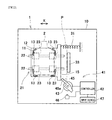
- Fig. 1 is a plan view showing an overall schematic configuration of a cell detachment device 1 according to one embodiment of the present invention.
- Fig. 2 is a schematic plan view of the cell detachment device 1, showing a state where a vessel holder 11 has moved from a reference position P.
- a flask-shaped culture vessel 2 is indicated by a two-dot chain line.
- Cells cultured in the culture vessel 2 adhere to the culture surface (mainly the inner bottom surface) in the culture vessel 2.
- the cell detachment device 1 is a device for detaching the cells from the culture surface of the culture vessel 2.
- the cell detachment device 1 includes: a base 10; the vessel holder 11, to which the culture vessel 2 is fitted; a guide mechanism 21 configured to guide reciprocating movement of the vessel holder 11; a collided member 33 configured to collide with the vessel holder 11 when the vessel holder 11 is moving; and an urging member 31 configured to urge the culture vessel 2 toward the collided member 33.
- the cell detachment device 1 further includes a power imparting mechanism 41 configured to impart, to the vessel holder 11, power for causing the vessel holder 11 to move while being guided by the guide mechanism 21.
- the vessel holder 11, the guide mechanism 21, the collided member 33, the urging member 31, and the power imparting mechanism 41 are each provided on the base 10.
- the components of the cell detachment device 1 are described in detail.
- the vessel holder 11 includes a plate-shaped board 12 and a holding frame 13 fixed on the board 12.
- One or a plurality of protrusions provided in a manner to rim at least four edges of the outline of the culture vessel 2 serve as the holding frame 13.
- the vessel holder 11 configured as above holds the culture vessel 2, such that the culture vessel 2 is unable to move substantially in the horizontal direction relative to the vessel holder 11, and the vessel holder 11 moves integrally with the culture vessel 2 substantially in the horizontal direction.
- the vessel holder 11 can hold the culture vessel 2 even if the size and type of the culture vessel 2 vary among a plurality of sizes and types. Therefore, for example, a plurality of types of vessel holders 11 may be fabricated, and the vessel holder 11 to use may be changed in accordance with the shape of the culture vessel 2. Alternatively, for example, a plurality of components attachable to and detachable from the board 12 may serve as the holding frame 13, and the attachment position of each component of the holding frame 13 on the board 12 may be changed in accordance with the shape of the culture vessel 2.
- the guide mechanism 21 includes one or a plurality of linear motion guides.
- the guide mechanism 21 according to the present embodiment includes two sets of linear motion guides.
- the two sets of linear motion guides include two rails 22 and four sliders 23.
- Two sliders 23 slidingly move on each rail 22.
- the two rails 22 are arranged substantially parallel to each other on the base 10, and are fixed to the base 10.
- the four sliders 23 are arranged and fixed on the lower surface of the board 12 in such a manner that the sliders 23 can support the vessel holder 11 in a balanced manner.
- the guide mechanism 21 with the above-described configuration guides the vessel holder 11 in a manner to allow the vessel holder 11 to make smooth reciprocating movement in a substantially horizontal direction relative to the base 10, and supports the vessel holder 11.
- the direction in which the vessel holder 11 moves in a reciprocating manner is simply referred to as a "moving direction X".
- the collided member 33 is a member configured to come into contact with the vessel holder 11 at the reference position P.
- the collided member 33 is a member configured to collide with the vessel holder 11 when the vessel holder 11 has made reciprocating movement and reached the reference position P.
- the state where the vessel holder 11 is at the "reference position P" is a state where the vessel holder 11 is positioned at one end of a reciprocating movement range of the vessel holder 11, the one end being a starting point of the reciprocating movement of the vessel holder 11.
- the collided member 33 is provided at the one end of the reciprocating movement range of the vessel holder 11.
- the collided member 33 is disposed such that the collided member 33 is lateral to the vessel holder 11 when the vessel holder 11 is at the reference position P, and is disposed on one side of the moving direction X outside the reciprocating movement range.
- the collided member 33 shown in Fig. 1 is in the shape of a block that is long in a direction substantially perpendicular to the moving direction X, the shape of the collided member 33 is not limited to a block shape, but the collided member 33 may be plate-shaped or columnar, for example.
- the urging member 31 is a member for urging the vessel holder 11 toward the collided member 33.
- the urging member 31 according to the present embodiment is a tension spring disposed such that the tension spring expands and contracts substantially parallel to the moving direction X.
- One end of the urging member 31 is fixed to the board 12 of the vessel holder 11, and the other end of the urging member 31 is fixed to the base 10.
- the tension spring serving as the urging member 31 is in the state of expanding from its natural length and is elastically deformed.
- the power imparting mechanism 41 is not in operation, the vessel holder 11 is in a standby state. In the standby state, the vessel holder 11 is at the reference position P and is in contact with the collided member 33 due to the action of the urging member 31.
- the power imparting mechanism 41 includes a motor 43 as a device that generates power for causing the vessel holder 11 to move.
- a power transmission system for transmitting the power from the motor 43 to a cam 45 is constructed so that rotational power can be transmitted from the output shaft of the motor 43 to the cam 45 directly or indirectly.
- the power imparting mechanism 41 further includes: a controller 42 configured to control the operation of the motor 43; a contacting or non-contacting rotation number sensor 46 configured to detect and output the number of rotations of the cam 45 to the controller 42; and an input device 47, with which an input to the controller 42 is made.
- a counting limit switch may be used as the rotation number sensor 46.
- the input device 47 includes; an operation switch for switching the device operation state between an operating state and an operation stopped state; and an input unit, with which to input the number of impact shocks to apply to the vessel holder 11.
- the cam 45 serves to convert a rotation output of the motor 43 into force for causing the vessel holder 11 to move, the force acting on the vessel holder 11.
- the cam 45 outputs rotational power of the motor 43 as force pushing the vessel holder 11 in the moving direction X away from the collided member 33.
- An action part 45a acting on the vessel holder 11 is formed on the cam 45.
- the rotation angle of the cam 45 is in a predetermined action range, the action part 45a of the cam 45 pushes an action-receiving part 15 of the vessel holder 11. In this manner, force causing the vessel holder 11 to move in the moving direction X away from the collided member 33 is imparted to the vessel holder 11.
- the action part 45a of the cam 45 does not act on the vessel holder 11. Accordingly, if the cam 45 rotates several revolutions, pushing force will be imparted to the vessel holder 11 intermittently.
- the action range of the cam 45 shown in Fig. 1 is 90° to 180°, the action range of the cam 45 may be suitably set.
- the culture vessel 2 is fitted to the vessel holder 11 at the reference position P.
- cells in the culture vessel 2 have already been treated by means of a proteolytic enzyme or the like so that the cells can be readily detached from the culture vessel 2.
- An operator turns on the operation switch after setting the number of impact shocks to apply by the input device 47.
- the controller 42 causes the motor 43 to operate such that the cam 45 rotates a number of revolutions corresponding to an optimal number of impact shocks to apply, which is inputted from the input device 47.
- a moving stroke of the vessel holder 11 when the vessel holder 11 is pushed by the cam 45 is approximately 10 mm. Desirably, the moving stroke of the vessel holder 11 in its reciprocating movement is 10 mm or more.
- the urging force of the urging member 31 causes the vessel holder 11 to move in the moving direction X toward the collided member 33.
- the vessel holder 11 collides with the collided member 33.
- the collided member 33 applies an impact shock to the vessel holder 11, and also restricts the movement of the vessel holder 11 in a direction toward the collided member 33.
- the vessel holder 11 temporarily moves away from the collided member 33 by counteraction.
- the vessel holder 11 moves toward the collided member 33 again owing to the urging force of the urging member 31.
- the vessel holder 11 continues vibrating with a reduced vibration width.
- the spring constant of the urging member 31 is suitably chosen so that the vibration having such a reduced vibration width will occur. The vibration diminishes, and the vessel holder 11 eventually stops at the reference position P.
- the vessel holder 11 repeats the above-described reciprocating movement and collision with the collided member 33.
- the series of operations of the cell detachment device 1 thus described is repeated for a number of times corresponding to the set number of impact shocks to apply.
- An impact shock and a vibration are regularly applied to the vessel holder 11 by a number of times corresponding to the number of impact shocks to apply.
- An optimal number of impact shocks to apply is different depending on the type and culturing conditions of the cells. Therefore, it is desirable to experimentally obtain the minimum number of impact shocks to apply necessary for detaching the cells from the culture vessel 2, and set it as the number of impact shocks to apply.
- the culture vessel 2 fitted to the vessel holder 11 also moves.
- the culture vessel 2 can be vibrated.
- the vessel holder 11 collides with the collided member 33 as described above an impact shock received by the vessel holder 11 is transmitted to the culture vessel 2.
- a vibration is applied to the culture vessel owing to the impact shock received by the vessel holder 11.
- the cell detachment device 1 can perform both vibrating the culture vessel 2 and applying an impact shock to the culture vessel 2.
- the impact shock applied to the culture vessel 2 causes displacement between the culture surface of the culture vessel 2 and the cells.
- a liquid surface in the culture vessel 2 ripples owing to the vibration of the culture vessel 2, the impact shock received by the culture vessel 2, and a vibration caused by the impact shock.
- the cell detachment is facilitated.
- the culture vessel 2 vibrates and receives an impact shock. This makes it possible to sufficiently and efficiently detach the cells from the culture vessel 2.
- the collided member 33 makes a direct collision not with the culture vessel 2 but with the vessel holder 11. This makes it possible to move (vibrate) the entire outer bottom surface of the culture vessel 2 in a single direction in a single amount and make the manner in which the impact shock is transmitted to the culture vessel 2 uniform. Moreover, even if the culture vessel 2 has an increased size of the culture surface, the impact shock and vibration can be evenly transmitted in the culture vessel 2. Since the vibration and impact shock are evenly transmitted to the culture vessel 2 in this manner, unevenness in the cell detachment can be reduced. This consequently makes it possible to improve the cell collection rate.
- the collided member 33 does not make a direct collision with the culture vessel 2, deformation of and damage to the culture vessel 2 can be prevented. It should be noted that, in conventional manual tapping, since the culture vessel is directly hit, the impact shock tends to be transmitted unevenly. In addition, in a case where the culture vessel has a large culture surface area, it is necessary to hit several parts of the culture vessel. This further increases unevenness in the transmission of the impact shock.
- the cell detachment device 1 according to the present embodiment also solves these problems.
- the above-described cell detachment device 1 includes the motor 43 and the cam 45 as the power imparting mechanism 41
- the cell detachment device 1 may be modified such that the motor 43 and the cam 45 are replaced by solenoid actuators with moving cores.
- the configuration of the power imparting mechanism 41 is not limited to the one described in the above embodiment, and the power imparting mechanism 41 may be configured in any manner, so long as the power imparting mechanism 41 is configured to impart the force for causing the reciprocating movement of the vessel holder 11 to the vessel holder 11 or the guide mechanism 21.
- the cell detachment device 1 may be modified such that the collided member 33 makes a direction collision with the culture vessel 2.
- cushioning be provided on the contact surface of the collided member 33.
- Fig. 3 is a plan view showing a schematic configuration of a cell detachment device according to Variation 1.
- components that are the same as or similar to those described in the above embodiment are denoted by the same reference signs as those used in the above embodiment, and repeating the same descriptions is avoided.
- a first collided member 33A is disposed outside of one end of the reciprocating movement range of the vessel holder 11, and a second collided member 33B is disposed outside of the other end of the reciprocating movement range of the vessel holder 11.
- the vessel holder 11 collides with the first collided member 33A after moving forward from the reference position P, and then collides with the second collided member 33B after moving forward. That is, the vessel holder 11 collides with the collided members 33A and 33B in the forward and backward paths of the reciprocating movement, respectively, thereby receiving impact shocks.
- the number of impact shocks to apply can be increased relative to the number of vibrations of the vessel holder 11, and thereby the cell detachment from the culture vessel 2 can be facilitated.
- Fig. 4 is a plan view showing a schematic configuration of a cell detachment device according to Variation 2.
- components that are the same as or similar to those described in the above embodiment are denoted by the same reference signs as those used in the above embodiment, and repeating the same descriptions is avoided. As shown in Fig.
- an urging member 31A which is a compression spring, is disposed at the opposite side to the collided member 33 with the vessel holder 11 positioned between the urging member 31A and the collided member 33, such that the urging member 31A expands and contracts substantially parallel to the moving direction X.
- One end of the urging member 31A is fixed to the base 10, and the other end of the urging member 31A is fixed to the vessel holder 11. According to this configuration, when the vessel holder 11 receives pushing force from the cam 45 and moves in a direction away from the collided member 33, the urging member 31A is compressed.
- the urging member 31A recovers elastically, and thereby the vessel holder 11 is urged toward the collided member 33.
- a spring is adopted as the urging member 31 in the above-described cell detachment device 1, the urging member 31 is not limited to a spring, but may be an elastic member such as rubber.
Landscapes
- Health & Medical Sciences (AREA)
- Life Sciences & Earth Sciences (AREA)
- Organic Chemistry (AREA)
- Engineering & Computer Science (AREA)
- Bioinformatics & Cheminformatics (AREA)
- Chemical & Material Sciences (AREA)
- Zoology (AREA)
- Wood Science & Technology (AREA)
- Sustainable Development (AREA)
- Microbiology (AREA)
- Biotechnology (AREA)
- Biomedical Technology (AREA)
- Biochemistry (AREA)
- General Engineering & Computer Science (AREA)
- General Health & Medical Sciences (AREA)
- Genetics & Genomics (AREA)
- Molecular Biology (AREA)
- Apparatus Associated With Microorganisms And Enzymes (AREA)
Abstract
Description
- The present invention relates to a device for use in cell culturing and particularly to a device for detaching cultured cells growing on the culture surface of a culture vessel from the culture surface.
- In recent years, cell culturing techniques for culturing cells and regenerative medical techniques utilizing cultured cells have been drawing attention. One of the important operations in cell culturing is cell subcultuung. Generally speaking, cell subculturing includes the steps of: cleaning cells in a culture vessel; detaching the cells from the culture vessel; collecting cell suspension from the culture vessel; and seeding the cells collected from the cell suspension in a new culture vessel. In the cell subculturing, the step of detaching the cells from the culture vessel is one of the important steps since the detachment of the cells is a major factor that affects the amount of cells to be collected, the degree of damage to the cells, an engraftment rate thereafter, etc. The step of detaching the cells from the culture vessel includes the work of: treating the cells by means of, for example, a proteolytic enzyme such that the cells become easily detachable from the culture vessel; then pipetting by an operator; hitting the side and the bottom part of the culture vessel several times by the operator; and intensely shaking the culture vessel by the operator. The work of hitting the side and the bottom part of the culture vessel is called tapping.
- Although the tapping was conventionally performed manually, there has been a proposal to mechanically automate the tapping. For example,
Patent Literature 1 discloses a device for detaching cells from a culture vessel by repeatedly applying horizontal impact force to the culture vessel. This device includes: a placing stand, on which a flat culture vessel can be placed; and a vibration exciter configured to apply a pulse-like impact shock to the culture vessel. The vibration exciter includes a plunger configured to advance or retract by means of a solenoid. A hitting part configured to come into contact with the side of the culture vessel is provided on the distal end of the plunger. - PTL 1: Japanese Laid-Open Patent Application Publication No.
S58-158182 - When performing the tapping manually, an operator holds and supports a culture vessel with one hand, and taps the side of the culture vessel with the other hand several times. Through the tapping, both impact shocks and vibrations are applied to the culture vessel. According to an experiment conducted by the inventors of the present invention, merely applying either impact shocks or vibrations to a culture vessel was not enough to sufficiently detach cultured cells from the culture vessel. From this experiment, the inventors have found out that it is effective to apply both impact shocks and vibrations to the culture vessel for realizing sufficient and efficient detachment of the cultured cells.
- In the device disclosed in
Patent Literature 1, a recess slightly larger than the bottom part of the culture vessel is formed in the top surface of the placing stand, and the bottom part of the culture vessel is fitted in the recess with a slight play. Accordingly, the culture vessel hit by the vibration exciter is allowed to make slight horizontal movement in the recess of the placing stand. However, since the device ofPatent Literature 1 is not a mechanism that actively causes the culture vessel to move, the culture vessel comes closer to the side wall of the recess each time the culture vessel is hit. Eventually, the culture vessel becomes unable to vibrate. In the device disclosed inPatent Literature 1, since the width of the vibration of the culture vessel is small, ripping of a liquid surface in the culture vessel is presumed to be insufficient for effectively facilitating the cell detachment. - The present invention has been made in view of the above. An object of the present invention is to sufficiently and efficiently detach cultured cells from a culture vessel by both vibrating the culture vessel while actively moving the culture vessel and applying impact shocks to the culture vessel, and to consequently achieve automated tapping.
- A cell detachment device according to the present invention is a cell detachment device for detaching cultured cells from a culture vessel. The cell detachment device includes: a vessel holder, to which the culture vessel is to be fitted; a guide mechanism configured to guide reciprocating movement of the vessel holder; a collided member positioned at one end of a reciprocating movement range of the vessel holder; and an urging member configured to urge the vessel holder toward the collided member.
- According to the above configuration, the vessel holder can move in a reciprocating manner while being guided by the guide mechanism. When the vessel holder moves, the culture vessel fitted to the vessel holder also moves. By thus causing the culture vessel to move in a reciprocating manner, the culture vessel can be vibrated. When the vessel holder moves with great force toward the collided member, the vessel holder or the culture vessel fitted thereto collides with the collided member with a great impact. In this manner, an impact shock can be applied to the vessel holder and the culture vessel. The impact shock applied to the culture vessel causes displacement between the culture surface of the culture vessel and the cells. In addition, a liquid surface in the culture vessel ripples owing to the vibration of the culture vessel, the impact shock received by the culture vessel, and a vibration caused by the impact shock. As a result, the cell detachment is facilitated. In this manner, the culture vessel vibrates and receives an impact shock. This makes it possible to sufficiently and efficiently detach the cells from the culture vessel.
- Preferably, in the above cell detachment device, the collided member is configured to collide with the vessel holder.
- According to the above configuration, the vessel holder collides with the collided member, but the culture vessel does not directly collide with the collided member. This makes it possible to prevent deformation of and damage to the culture vessel due to the impact shock. Moreover, since the vibration of the culture vessel and the impact shock received by the culture vessel can be made uniform over the entire culture vessel, unevenness in cell detachment is reduced, and an improvement in cell collection rate can be expected. Furthermore, even if the culture vessel has an increased size of the culture surface, the entire culture vessel evenly vibrates and evenly receives the impact shock. Therefore, unevenness in cell detachment is reduced, and an improvement in cell collection rate can be expected.
- Preferably, the above cell detachment device includes a power imparting mechanism configured to impart, to the vessel holder, power for causing the vessel holder to move.
- According to the above configuration, reciprocating movement of the vessel holder can be automated, and tapping can be automated. Accordingly, the vessel holder moves in a reciprocating manner periodically. This makes it possible to regularly apply a vibration and an impact shock to the culture vessel.
- Preferably, in the above cell detachment device, the power imparting mechanism is configured to impart, to the vessel holder, force for causing the vessel holder to move in a direction away from the collided member.
- According to the above configuration, the force imparted to the vessel holder by the power imparting mechanism causes the vessel holder to move in a direction away from the collided member. When the force is eliminated, the urging force of the urging member causes the vessel holder to move with great force in a direction toward the collided member. In this manner, the vessel holder can be caused to move in a reciprocating manner. Also, the vessel holder or the culture vessel can be caused to collide with the collided member with a great impact.
- Preferably, in the above cell detachment device, the power imparting mechanism includes: a motor; and a cam configured to convert a rotation output of the motor into force acting on the vessel holder. More preferably, the cam includes: an action part acting on the vessel holder when a rotation angle of the cam is in a predetermined action range; and an action-receiving part not acting on the vessel holder when the rotation angle of the cam is out of the predetermined action range.
- According to the above configuration, the vessel holder is caused to move in a reciprocating manner periodically. This makes it possible to regularly apply a vibration and an impact shock to the vessel holder.
- Preferably, in the above cell detachment device, the power imparting mechanism includes a controller, and the controller controls operation of the power imparting mechanism such that the number of collisions between the vessel holder or the culture vessel fitted to the vessel holder and the collided member becomes a predetermined number of impact shocks.
- Preferably, the above cell detachment device includes: a rotation number sensor configured to detect the number of rotations of the cam; and a controller configured to control operation of the motor in accordance with a detection output that the controller receives from the rotation number sensor. The controller controls the operation of the motor such that the number of rotations of the cam becomes a predetermined number of impact shocks.
- According to the above configuration, an optimal number of impact shocks to apply for causing the cells to be detached from the culture vessel can be imparted to the culture vessel. This makes it possible to prevent insufficient cell detachment, and prevent excessive vibrations or impact shocks from being imparted to the culture vessel after the cells are detached from the culture vessel.
- Preferably, in the above cell detachment device, the urging member is a spring.
- The above configuration allows the vessel holder to continue vibrating after colliding with the collided member. This makes it possible to apply a vibration to the culture vessel held by the vessel holder.
- Preferably, the above cell detachment device includes a second collided member, which is disposed at another end of the reciprocating movement range of the vessel holder.
- According to the above configuration, the vessel holder comes into contact with the collided members in both forward and backward paths of the reciprocating movement. In this manner, the vessel holder can receive impact shocks.
- According to the present invention, both an impact shock and a vibration can be applied to the culture vessel. The detachment of the cultured cells from the culture vessel is facilitated by rippling of the liquid surface, which is caused by the impact shock and the vibration applied to the culture vessel. As a result, the cultured cells can be sufficiently and efficiently detached from the culture vessel.
-
-
Fig. 1 is a plan view showing an overall schematic configuration of a cell detachment device according to one embodiment of the present invention. -
Fig. 2 is a schematic plan view of the cell detachment device, showing a state where a vessel holder has moved from a reference position. -
Fig. 3 is a plan view showing a schematic configuration of a cell detachment device according toVariation 1. -
Fig. 4 is a plan view showing a schematic configuration of a cell detachment device according toVariation 2. - Hereinafter, one embodiment of the present invention is described with reference to the drawings.
Fig. 1 is a plan view showing an overall schematic configuration of acell detachment device 1 according to one embodiment of the present invention.Fig. 2 is a schematic plan view of thecell detachment device 1, showing a state where avessel holder 11 has moved from a reference position P. InFig. 1 andFig. 2 , a flask-shapedculture vessel 2 is indicated by a two-dot chain line. Cells cultured in theculture vessel 2 adhere to the culture surface (mainly the inner bottom surface) in theculture vessel 2. Thecell detachment device 1 is a device for detaching the cells from the culture surface of theculture vessel 2. - As shown in
Fig. 1 , thecell detachment device 1 includes: a base 10; thevessel holder 11, to which theculture vessel 2 is fitted; aguide mechanism 21 configured to guide reciprocating movement of thevessel holder 11; a collidedmember 33 configured to collide with thevessel holder 11 when thevessel holder 11 is moving; and an urgingmember 31 configured to urge theculture vessel 2 toward the collidedmember 33. Thecell detachment device 1 further includes apower imparting mechanism 41 configured to impart, to thevessel holder 11, power for causing thevessel holder 11 to move while being guided by theguide mechanism 21. Thevessel holder 11, theguide mechanism 21, the collidedmember 33, the urgingmember 31, and thepower imparting mechanism 41 are each provided on thebase 10. Hereinafter, the components of thecell detachment device 1 are described in detail. - The
vessel holder 11 includes a plate-shapedboard 12 and a holdingframe 13 fixed on theboard 12. One or a plurality of protrusions provided in a manner to rim at least four edges of the outline of theculture vessel 2 serve as the holdingframe 13. When theculture vessel 2 is placed in the holdingframe 13, movement of theculture vessel 2 substantially in the horizontal direction is restricted by the holdingframe 13. Thevessel holder 11 configured as above holds theculture vessel 2, such that theculture vessel 2 is unable to move substantially in the horizontal direction relative to thevessel holder 11, and thevessel holder 11 moves integrally with theculture vessel 2 substantially in the horizontal direction. - Desirably, the
vessel holder 11 can hold theculture vessel 2 even if the size and type of theculture vessel 2 vary among a plurality of sizes and types. Therefore, for example, a plurality of types ofvessel holders 11 may be fabricated, and thevessel holder 11 to use may be changed in accordance with the shape of theculture vessel 2. Alternatively, for example, a plurality of components attachable to and detachable from theboard 12 may serve as the holdingframe 13, and the attachment position of each component of the holdingframe 13 on theboard 12 may be changed in accordance with the shape of theculture vessel 2. - The
guide mechanism 21 includes one or a plurality of linear motion guides. Theguide mechanism 21 according to the present embodiment includes two sets of linear motion guides. The two sets of linear motion guides include tworails 22 and foursliders 23. Twosliders 23 slidingly move on eachrail 22. The tworails 22 are arranged substantially parallel to each other on thebase 10, and are fixed to thebase 10. The foursliders 23 are arranged and fixed on the lower surface of theboard 12 in such a manner that thesliders 23 can support thevessel holder 11 in a balanced manner. Theguide mechanism 21 with the above-described configuration guides thevessel holder 11 in a manner to allow thevessel holder 11 to make smooth reciprocating movement in a substantially horizontal direction relative to thebase 10, and supports thevessel holder 11. Hereinafter, the direction in which thevessel holder 11 moves in a reciprocating manner is simply referred to as a "moving direction X". - The collided
member 33 is a member configured to come into contact with thevessel holder 11 at the reference position P. The collidedmember 33 is a member configured to collide with thevessel holder 11 when thevessel holder 11 has made reciprocating movement and reached the reference position P. The state where thevessel holder 11 is at the "reference position P" is a state where thevessel holder 11 is positioned at one end of a reciprocating movement range of thevessel holder 11, the one end being a starting point of the reciprocating movement of thevessel holder 11. The collidedmember 33 is provided at the one end of the reciprocating movement range of thevessel holder 11. To be more specific, the collidedmember 33 is disposed such that the collidedmember 33 is lateral to thevessel holder 11 when thevessel holder 11 is at the reference position P, and is disposed on one side of the moving direction X outside the reciprocating movement range. Although the collidedmember 33 shown inFig. 1 is in the shape of a block that is long in a direction substantially perpendicular to the moving direction X, the shape of the collidedmember 33 is not limited to a block shape, but the collidedmember 33 may be plate-shaped or columnar, for example. - The urging
member 31 is a member for urging thevessel holder 11 toward the collidedmember 33. The urgingmember 31 according to the present embodiment is a tension spring disposed such that the tension spring expands and contracts substantially parallel to the moving direction X. One end of the urgingmember 31 is fixed to theboard 12 of thevessel holder 11, and the other end of the urgingmember 31 is fixed to thebase 10. When thevessel holder 11 is at the reference position P, the tension spring serving as the urgingmember 31 is in the state of expanding from its natural length and is elastically deformed. While thepower imparting mechanism 41 is not in operation, thevessel holder 11 is in a standby state. In the standby state, thevessel holder 11 is at the reference position P and is in contact with the collidedmember 33 due to the action of the urgingmember 31. - The
power imparting mechanism 41 includes amotor 43 as a device that generates power for causing thevessel holder 11 to move. A power transmission system for transmitting the power from themotor 43 to acam 45 is constructed so that rotational power can be transmitted from the output shaft of themotor 43 to thecam 45 directly or indirectly. Thepower imparting mechanism 41 further includes: acontroller 42 configured to control the operation of themotor 43; a contacting or non-contactingrotation number sensor 46 configured to detect and output the number of rotations of thecam 45 to thecontroller 42; and aninput device 47, with which an input to thecontroller 42 is made. For example, a counting limit switch may be used as therotation number sensor 46. Theinput device 47 includes; an operation switch for switching the device operation state between an operating state and an operation stopped state; and an input unit, with which to input the number of impact shocks to apply to thevessel holder 11. - The
cam 45 serves to convert a rotation output of themotor 43 into force for causing thevessel holder 11 to move, the force acting on thevessel holder 11. Thecam 45 outputs rotational power of themotor 43 as force pushing thevessel holder 11 in the moving direction X away from the collidedmember 33. Anaction part 45a acting on thevessel holder 11 is formed on thecam 45. When the rotation angle of thecam 45 is in a predetermined action range, theaction part 45a of thecam 45 pushes an action-receivingpart 15 of thevessel holder 11. In this manner, force causing thevessel holder 11 to move in the moving direction X away from the collidedmember 33 is imparted to thevessel holder 11. On the other hand, when the rotation angle of thecam 45 is out of the action range (i.e., in a non-action range), theaction part 45a of thecam 45 does not act on thevessel holder 11. Accordingly, if thecam 45 rotates several revolutions, pushing force will be imparted to thevessel holder 11 intermittently. Although the action range of thecam 45 shown inFig. 1 is 90° to 180°, the action range of thecam 45 may be suitably set. - Hereinafter, the operation of the
cell detachment device 1 is described. In preparation for operating thecell detachment device 1, theculture vessel 2 is fitted to thevessel holder 11 at the reference position P. At the time, cells in theculture vessel 2 have already been treated by means of a proteolytic enzyme or the like so that the cells can be readily detached from theculture vessel 2. - An operator turns on the operation switch after setting the number of impact shocks to apply by the
input device 47. In response, thecontroller 42 causes themotor 43 to operate such that thecam 45 rotates a number of revolutions corresponding to an optimal number of impact shocks to apply, which is inputted from theinput device 47. - When the
motor 43 is driven, thecam 45 rotates, accordingly. When the rotation angle of thecam 45 falls within the action range, thecam 45 pushes thevessel holder 11 in a direction away from the collidedmember 33. In other words, force causing thevessel holder 11 to move in the direction away from the collidedmember 33 is imparted to thevessel holder 11. As a result, thevessel holder 11 moves in the direction away from the collidedmember 33 against the urging force of the urging member 31 (seeFig. 2 ). It should be noted that, in the present embodiment, a moving stroke of thevessel holder 11 when thevessel holder 11 is pushed by thecam 45 is approximately 10 mm. Desirably, the moving stroke of thevessel holder 11 in its reciprocating movement is 10 mm or more. - When the rotation angle of the
cam 45 has shifted from the action range into the non-action range, the pushing force imparted to thevessel holder 11 by thecam 45 is eliminated. Accordingly, the urging force of the urgingmember 31 causes thevessel holder 11 to move in the moving direction X toward the collidedmember 33. As a result of moving in the moving direction X toward the collidedmember 33, thevessel holder 11 collides with the collidedmember 33. At the time, the collidedmember 33 applies an impact shock to thevessel holder 11, and also restricts the movement of thevessel holder 11 in a direction toward the collidedmember 33. After colliding with the collidedmember 33, thevessel holder 11 temporarily moves away from the collidedmember 33 by counteraction. Thereafter, thevessel holder 11 moves toward the collidedmember 33 again owing to the urging force of the urgingmember 31. In this manner, after colliding with the collidedmember 33, thevessel holder 11 continues vibrating with a reduced vibration width. The spring constant of the urgingmember 31 is suitably chosen so that the vibration having such a reduced vibration width will occur. The vibration diminishes, and thevessel holder 11 eventually stops at the reference position P. - When the rotation angle of the
cam 45 has shifted from the non-action range into the action range again, thevessel holder 11 repeats the above-described reciprocating movement and collision with the collidedmember 33. The series of operations of thecell detachment device 1 thus described is repeated for a number of times corresponding to the set number of impact shocks to apply. An impact shock and a vibration are regularly applied to thevessel holder 11 by a number of times corresponding to the number of impact shocks to apply. An optimal number of impact shocks to apply is different depending on the type and culturing conditions of the cells. Therefore, it is desirable to experimentally obtain the minimum number of impact shocks to apply necessary for detaching the cells from theculture vessel 2, and set it as the number of impact shocks to apply. - When the
vessel holder 11 moves in a reciprocating manner while being guided by theguide mechanism 21 in the above-described manner, theculture vessel 2 fitted to thevessel holder 11 also moves. By thus causing theculture vessel 2 to move in a reciprocating manner, theculture vessel 2 can be vibrated. When thevessel holder 11 collides with the collidedmember 33 as described above, an impact shock received by thevessel holder 11 is transmitted to theculture vessel 2. In addition, a vibration is applied to the culture vessel owing to the impact shock received by thevessel holder 11. In this manner, thecell detachment device 1 can perform both vibrating theculture vessel 2 and applying an impact shock to theculture vessel 2. The impact shock applied to theculture vessel 2 causes displacement between the culture surface of theculture vessel 2 and the cells. In addition, a liquid surface in theculture vessel 2 ripples owing to the vibration of theculture vessel 2, the impact shock received by theculture vessel 2, and a vibration caused by the impact shock. As a result of the rippling of the liquid surface, the cell detachment is facilitated. Thus, according to thecell detachment device 1 of the present embodiment, theculture vessel 2 vibrates and receives an impact shock. This makes it possible to sufficiently and efficiently detach the cells from theculture vessel 2. - In the above-described operation of the
cell detachment device 1, the collidedmember 33 makes a direct collision not with theculture vessel 2 but with thevessel holder 11. This makes it possible to move (vibrate) the entire outer bottom surface of theculture vessel 2 in a single direction in a single amount and make the manner in which the impact shock is transmitted to theculture vessel 2 uniform. Moreover, even if theculture vessel 2 has an increased size of the culture surface, the impact shock and vibration can be evenly transmitted in theculture vessel 2. Since the vibration and impact shock are evenly transmitted to theculture vessel 2 in this manner, unevenness in the cell detachment can be reduced. This consequently makes it possible to improve the cell collection rate. Furthermore, since the collidedmember 33 does not make a direct collision with theculture vessel 2, deformation of and damage to theculture vessel 2 can be prevented. It should be noted that, in conventional manual tapping, since the culture vessel is directly hit, the impact shock tends to be transmitted unevenly. In addition, in a case where the culture vessel has a large culture surface area, it is necessary to hit several parts of the culture vessel. This further increases unevenness in the transmission of the impact shock. Thecell detachment device 1 according to the present embodiment also solves these problems. - Although one preferred embodiment of the present invention has been described above, the configuration described above may be modified, for example, in a manner described below.
- As one example, although the above-described
cell detachment device 1 includes themotor 43 and thecam 45 as thepower imparting mechanism 41, thecell detachment device 1 may be modified such that themotor 43 and thecam 45 are replaced by solenoid actuators with moving cores. Thus, the configuration of thepower imparting mechanism 41 is not limited to the one described in the above embodiment, and thepower imparting mechanism 41 may be configured in any manner, so long as thepower imparting mechanism 41 is configured to impart the force for causing the reciprocating movement of thevessel holder 11 to thevessel holder 11 or theguide mechanism 21. - As another example, although the
vessel holder 11 directly collides with the collidedmember 33 in the above-describedcell detachment device 1, thecell detachment device 1 may be modified such that the collidedmember 33 makes a direction collision with theculture vessel 2. In this case, it is desirable to set the contact surface of the collidedmember 33 sufficiently large so that theculture vessel 2 will receive the impact shock more evenly. In addition, it is desirable that cushioning be provided on the contact surface of the collidedmember 33. - As yet another example, although the collided
member 33 is disposed at one end of the reciprocating movement range of thevessel holder 11 in the above-describedcell detachment device 1, the collidedmember 33 may be disposed at both sides of the reciprocating movement range.Fig. 3 is a plan view showing a schematic configuration of a cell detachment device according toVariation 1. InFig. 3 and the description below, components that are the same as or similar to those described in the above embodiment are denoted by the same reference signs as those used in the above embodiment, and repeating the same descriptions is avoided. In thecell detachment device 1 shown inFig. 3 , a first collidedmember 33A is disposed outside of one end of the reciprocating movement range of thevessel holder 11, and a second collidedmember 33B is disposed outside of the other end of the reciprocating movement range of thevessel holder 11. According to this configuration, thevessel holder 11 collides with the first collidedmember 33A after moving forward from the reference position P, and then collides with the second collidedmember 33B after moving forward. That is, thevessel holder 11 collides with the collidedmembers vessel holder 11, and thereby the cell detachment from theculture vessel 2 can be facilitated. - As yet another example, in the above-described
cell detachment device 1, the tension spring serving as the urgingmember 31 may be replaced by a compression spring.Fig. 4 is a plan view showing a schematic configuration of a cell detachment device according toVariation 2. InFig. 4 and the description below, components that are the same as or similar to those described in the above embodiment are denoted by the same reference signs as those used in the above embodiment, and repeating the same descriptions is avoided. As shown inFig. 4 , an urgingmember 31A, which is a compression spring, is disposed at the opposite side to the collidedmember 33 with thevessel holder 11 positioned between the urgingmember 31A and the collidedmember 33, such that the urgingmember 31A expands and contracts substantially parallel to the moving direction X. One end of the urgingmember 31A is fixed to thebase 10, and the other end of the urgingmember 31A is fixed to thevessel holder 11. According to this configuration, when thevessel holder 11 receives pushing force from thecam 45 and moves in a direction away from the collidedmember 33, the urgingmember 31A is compressed. When the pushing force applied to thevessel holder 11 from thecam 45 is eliminated, the urgingmember 31A recovers elastically, and thereby thevessel holder 11 is urged toward the collidedmember 33. Although a spring is adopted as the urgingmember 31 in the above-describedcell detachment device 1, the urgingmember 31 is not limited to a spring, but may be an elastic member such as rubber. - While the embodiment and the variations of the present invention have been described above with reference to the drawings, it will be understood that those skilled in the art, upon attaining an understanding of the foregoing, will readily conceive of various alterations and modifications without departing from the scope of the present invention. Therefore, such alterations and modifications are construed to fall within the scope of the present invention, which is defined by the claims.
-
- 1
- cell detachment device
- 2
- culture vessel
- 11
- vessel holder
- 12
- board
- 13
- holding frame
- 15
- action-receiving part
- 21
- guide mechanism
- 22
- rail
- 23
- slider
- 31
- urging member
- 33
- collided member
- 41
- power imparting mechanism
- 42
- controller
- 43
- motor
- 45
- cam
- 45a
- action part
- 46
- rotation number sensor
- 47
- input device
Claims (10)
- A cell detachment device for detaching cultured cells from a culture vessel, the cell detachment device comprising:a vessel holder, to which the culture vessel is to be fitted;a guide mechanism configured to guide reciprocating movement of the vessel holder;a collided member positioned at one end of a reciprocating movement range of the vessel holder; andan urging member configured to urge the vessel holder toward the collided member.
- The cell detachment device according to claim 1, wherein
the collided member is configured to collide with the vessel holder. - The cell detachment device according to claim 1 or 2, comprising a power imparting mechanism configured to impart, to the vessel holder, power for causing the vessel holder to move.
- The cell detachment device according to claim 3, wherein
the power imparting mechanism is configured to impart, to the vessel holder, force for causing the vessel holder to move in a direction away from the collided member. - The cell detachment device according to claim 3 or 4, wherein
the power imparting mechanism includes:a motor; anda cam configured to convert a rotation output of the motor into force acting on the vessel holder. - The cell detachment device according to claim 5, wherein
the cam acts on the vessel holder when a rotation angle of the cam is in a predetermined action range, and the cam does not act on the vessel holder when the rotation angle of the cam is out of the predetermined action range. - The cell detachment device according to any one of claims 3 to 6, wherein
the power imparting mechanism includes a controller, and
the controller controls operation of the power imparting mechanism such that the number of collisions between the vessel holder or the culture vessel fitted to the vessel holder and the collided member becomes a predetermined number of impact shocks. - The cell detachment device according to claim 5 or 6, comprising:a rotation number sensor configured to detect the number of rotations of the cam; anda controller configured to control operation of the motor in accordance with a detection output that the controller receives from the rotation number sensor, whereinthe controller controls the operation of the motor such that the number of rotations of the cam becomes a predetermined number of impact shocks.
- The cell detachment device according to any one of claims 1 to 8, wherein the urging member is a spring.
- The cell detachment device according to any one of claims 1 to 9, comprising a second collided member, which is disposed at another end of the reciprocating movement range of the vessel holder.
Applications Claiming Priority (2)
| Application Number | Priority Date | Filing Date | Title |
|---|---|---|---|
| JP2012271566A JP6132537B2 (en) | 2012-12-12 | 2012-12-12 | Cell peeling device |
| PCT/JP2013/007191 WO2014091731A1 (en) | 2012-12-12 | 2013-12-06 | Cell detachment device |
Publications (3)
| Publication Number | Publication Date |
|---|---|
| EP2933324A1 true EP2933324A1 (en) | 2015-10-21 |
| EP2933324A4 EP2933324A4 (en) | 2016-08-24 |
| EP2933324B1 EP2933324B1 (en) | 2018-04-25 |
Family
ID=50934039
Family Applications (1)
| Application Number | Title | Priority Date | Filing Date |
|---|---|---|---|
| EP13863213.8A Not-in-force EP2933324B1 (en) | 2012-12-12 | 2013-12-06 | Cell detachment device |
Country Status (4)
| Country | Link |
|---|---|
| US (1) | US9938494B2 (en) |
| EP (1) | EP2933324B1 (en) |
| JP (1) | JP6132537B2 (en) |
| WO (1) | WO2014091731A1 (en) |
Families Citing this family (5)
| Publication number | Priority date | Publication date | Assignee | Title |
|---|---|---|---|---|
| WO2018161204A1 (en) * | 2017-03-06 | 2018-09-13 | 东北大学 | Enclosed mixture stirrer using intermittent resonance and method |
| JP2025141198A (en) * | 2024-03-15 | 2025-09-29 | キヤノン株式会社 | Cell detachment device, cell detachment system, cell detachment method, and program |
| JP2025141150A (en) | 2024-03-15 | 2025-09-29 | キヤノン株式会社 | Cell detachment system and cell detachment method |
| JP2025141151A (en) | 2024-03-15 | 2025-09-29 | キヤノン株式会社 | Cell detachment method and cell detachment system |
| JP2026013936A (en) | 2024-07-18 | 2026-01-29 | キヤノン株式会社 | Cell detachment device |
Family Cites Families (20)
| Publication number | Priority date | Publication date | Assignee | Title |
|---|---|---|---|---|
| US3926733A (en) * | 1972-09-27 | 1975-12-16 | Tanabe Seiyaku Co | Method of continuous automatic incubation of bacteria and determination of growth thereof, and apparatus therefor |
| JPS5339510B2 (en) * | 1972-09-27 | 1978-10-21 | ||
| US4208484A (en) * | 1977-03-22 | 1980-06-17 | Olympus Optical Co., Ltd. | Apparatus for handling centrifuge tubes in automatic culture system |
| DE2804316A1 (en) * | 1978-02-01 | 1979-08-02 | Siemens Ag | DOSING DEVICE FOR LIQUID MEDIA |
| JPS56154988A (en) * | 1980-05-02 | 1981-11-30 | Olympus Optical Co Ltd | Releasing method of cultured cells and device therefor |
| JPS58155087A (en) * | 1982-03-12 | 1983-09-14 | Olympus Optical Co Ltd | Automatic cultivating process for cell and its device |
| JPS58158182A (en) | 1982-03-15 | 1983-09-20 | Olympus Optical Co Ltd | Method and apparatus for peeling cultured cell |
| JPH0885483A (en) * | 1994-09-19 | 1996-04-02 | Ougi Kogyo:Kk | Bicycle bell device |
| JPH10229684A (en) * | 1997-02-14 | 1998-08-25 | Seiko Epson Corp | Piezoelectric generator and portable equipment |
| US6659637B2 (en) * | 2000-10-03 | 2003-12-09 | Union Scientific Corporation | Vertical electromagnetic shaker for biological and chemical specimens |
| JP4666335B2 (en) * | 2002-09-04 | 2011-04-06 | 晶夫 岸田 | Biological function control method and apparatus by mechanical vibration |
| US7116928B2 (en) * | 2002-12-18 | 2006-10-03 | Ricoh Company, Ltd. | Powder discharging device and image forming apparatus using the same |
| KR100671780B1 (en) | 2005-02-25 | 2007-01-19 | 배석규 | Experimental Stirring Device |
| KR100624464B1 (en) * | 2005-03-29 | 2006-09-19 | 삼성전자주식회사 | Semi-Automatic Microchip Switchgear |
| JP4775218B2 (en) * | 2006-09-28 | 2011-09-21 | 千代田化工建設株式会社 | Closed system cell recovery device, cell culture device, cell recovery method and culture method |
| JP4991353B2 (en) * | 2006-10-23 | 2012-08-01 | 廣幸 小川 | Mixing equipment |
| JP2010142143A (en) * | 2008-12-17 | 2010-07-01 | Sanyo Electric Co Ltd | Cell culture container and cell culture apparatus |
| WO2010118709A2 (en) * | 2009-04-16 | 2010-10-21 | Univerzita Palackeho | Method of production of synchronized adherently growing cell lines and device for carrying out said method |
| JP4890622B2 (en) * | 2010-02-24 | 2012-03-07 | 守秀 橋本 | Ground improvement mixing and stirring device, and ground improvement mixing and stirring method |
| JP2015505472A (en) * | 2012-02-02 | 2015-02-23 | コーニング インコーポレイテッド | Cell culture system |
-
2012
- 2012-12-12 JP JP2012271566A patent/JP6132537B2/en not_active Expired - Fee Related
-
2013
- 2013-12-06 WO PCT/JP2013/007191 patent/WO2014091731A1/en not_active Ceased
- 2013-12-06 EP EP13863213.8A patent/EP2933324B1/en not_active Not-in-force
- 2013-12-06 US US14/650,053 patent/US9938494B2/en not_active Expired - Fee Related
Also Published As
| Publication number | Publication date |
|---|---|
| US20150315537A1 (en) | 2015-11-05 |
| EP2933324A4 (en) | 2016-08-24 |
| EP2933324B1 (en) | 2018-04-25 |
| JP2014113133A (en) | 2014-06-26 |
| US9938494B2 (en) | 2018-04-10 |
| JP6132537B2 (en) | 2017-05-24 |
| WO2014091731A1 (en) | 2014-06-19 |
Similar Documents
| Publication | Publication Date | Title |
|---|---|---|
| US9938494B2 (en) | Cell detachment device | |
| CN108998444B (en) | A transfer liquid nucleic acid extraction device and method | |
| RU2017129879A (en) | DEVELOPER FEED CONTAINER AND DEVELOPER FEED SYSTEM | |
| EP2555412A3 (en) | Ultrasonic motor and lens apparatus including the same | |
| JP6503187B2 (en) | Nozzle cleaning device | |
| EP2278431A3 (en) | Method and apparatus for generating vibrations in portable terminals | |
| CN201283280Y (en) | Magnetic suspension type sample oscillator | |
| CN103658439B (en) | Punch press punching waste material automatic clear frock and punch press | |
| ATE410047T1 (en) | METHOD FOR REMOVAL OF FRUIT FROM A PLANT AND APPARATUS FOR HARVESTING FRUIT | |
| NO20063806L (en) | Sheet joint system for pie forming apparatus | |
| CN104670862A (en) | Diverting system | |
| CN203470399U (en) | Optical lens cleaning machine | |
| CN101524036B (en) | Filling system of mushroom culture medium | |
| CN202061048U (en) | Finger massaging device | |
| CN203956912U (en) | Absorption type robot device | |
| CN103753647A (en) | Water cutting system driven by linear motors | |
| CN205149261U (en) | Automatic stamp making machine | |
| US20200124518A1 (en) | Sample liquid-sending apparatus, flow cytometer, and sample liquid-sending method | |
| CN211071785U (en) | Vibration sand cleaning machine | |
| WO2008126236A1 (en) | Driver | |
| CN204892661U (en) | Remove stamping workpiece equipment | |
| CN202206860U (en) | Vibration dehydrating device used in production of biological fresh-keeping bamboo shoot | |
| CN220114057U (en) | Nut pressing-in equipment | |
| CN202318195U (en) | Bottle cap gasket machine device | |
| CN210704602U (en) | Magnet pad foot assembly device |
Legal Events
| Date | Code | Title | Description |
|---|---|---|---|
| PUAI | Public reference made under article 153(3) epc to a published international application that has entered the european phase |
Free format text: ORIGINAL CODE: 0009012 |
|
| 17P | Request for examination filed |
Effective date: 20150710 |
|
| AK | Designated contracting states |
Kind code of ref document: A1 Designated state(s): AL AT BE BG CH CY CZ DE DK EE ES FI FR GB GR HR HU IE IS IT LI LT LU LV MC MK MT NL NO PL PT RO RS SE SI SK SM TR |
|
| AX | Request for extension of the european patent |
Extension state: BA ME |
|
| DAX | Request for extension of the european patent (deleted) | ||
| A4 | Supplementary search report drawn up and despatched |
Effective date: 20160722 |
|
| RIC1 | Information provided on ipc code assigned before grant |
Ipc: C12M 1/00 20060101AFI20160718BHEP |
|
| GRAP | Despatch of communication of intention to grant a patent |
Free format text: ORIGINAL CODE: EPIDOSNIGR1 |
|
| INTG | Intention to grant announced |
Effective date: 20171108 |
|
| RIN1 | Information on inventor provided before grant (corrected) |
Inventor name: WATAKABE, KEIZO Inventor name: HASUNUMA, HITOSHI Inventor name: NAKASHIMA, KATSUMI Inventor name: IIZAKA, JUNJI |
|
| GRAA | (expected) grant |
Free format text: ORIGINAL CODE: 0009210 |
|
| GRAS | Grant fee paid |
Free format text: ORIGINAL CODE: EPIDOSNIGR3 |
|
| AK | Designated contracting states |
Kind code of ref document: B1 Designated state(s): AL AT BE BG CH CY CZ DE DK EE ES FI FR GB GR HR HU IE IS IT LI LT LU LV MC MK MT NL NO PL PT RO RS SE SI SK SM TR |
|
| REG | Reference to a national code |
Ref country code: GB Ref legal event code: FG4D |
|
| REG | Reference to a national code |
Ref country code: CH Ref legal event code: EP |
|
| REG | Reference to a national code |
Ref country code: AT Ref legal event code: REF Ref document number: 992927 Country of ref document: AT Kind code of ref document: T Effective date: 20180515 |
|
| REG | Reference to a national code |
Ref country code: IE Ref legal event code: FG4D |
|
| REG | Reference to a national code |
Ref country code: DE Ref legal event code: R096 Ref document number: 602013036689 Country of ref document: DE |
|
| REG | Reference to a national code |
Ref country code: NL Ref legal event code: MP Effective date: 20180425 |
|
| REG | Reference to a national code |
Ref country code: LT Ref legal event code: MG4D |
|
| PG25 | Lapsed in a contracting state [announced via postgrant information from national office to epo] |
Ref country code: NL Free format text: LAPSE BECAUSE OF FAILURE TO SUBMIT A TRANSLATION OF THE DESCRIPTION OR TO PAY THE FEE WITHIN THE PRESCRIBED TIME-LIMIT Effective date: 20180425 |
|
| PG25 | Lapsed in a contracting state [announced via postgrant information from national office to epo] |
Ref country code: BG Free format text: LAPSE BECAUSE OF FAILURE TO SUBMIT A TRANSLATION OF THE DESCRIPTION OR TO PAY THE FEE WITHIN THE PRESCRIBED TIME-LIMIT Effective date: 20180725 Ref country code: NO Free format text: LAPSE BECAUSE OF FAILURE TO SUBMIT A TRANSLATION OF THE DESCRIPTION OR TO PAY THE FEE WITHIN THE PRESCRIBED TIME-LIMIT Effective date: 20180725 Ref country code: LT Free format text: LAPSE BECAUSE OF FAILURE TO SUBMIT A TRANSLATION OF THE DESCRIPTION OR TO PAY THE FEE WITHIN THE PRESCRIBED TIME-LIMIT Effective date: 20180425 Ref country code: FI Free format text: LAPSE BECAUSE OF FAILURE TO SUBMIT A TRANSLATION OF THE DESCRIPTION OR TO PAY THE FEE WITHIN THE PRESCRIBED TIME-LIMIT Effective date: 20180425 Ref country code: SE Free format text: LAPSE BECAUSE OF FAILURE TO SUBMIT A TRANSLATION OF THE DESCRIPTION OR TO PAY THE FEE WITHIN THE PRESCRIBED TIME-LIMIT Effective date: 20180425 Ref country code: PL Free format text: LAPSE BECAUSE OF FAILURE TO SUBMIT A TRANSLATION OF THE DESCRIPTION OR TO PAY THE FEE WITHIN THE PRESCRIBED TIME-LIMIT Effective date: 20180425 Ref country code: ES Free format text: LAPSE BECAUSE OF FAILURE TO SUBMIT A TRANSLATION OF THE DESCRIPTION OR TO PAY THE FEE WITHIN THE PRESCRIBED TIME-LIMIT Effective date: 20180425 |
|
| PG25 | Lapsed in a contracting state [announced via postgrant information from national office to epo] |
Ref country code: RS Free format text: LAPSE BECAUSE OF FAILURE TO SUBMIT A TRANSLATION OF THE DESCRIPTION OR TO PAY THE FEE WITHIN THE PRESCRIBED TIME-LIMIT Effective date: 20180425 Ref country code: HR Free format text: LAPSE BECAUSE OF FAILURE TO SUBMIT A TRANSLATION OF THE DESCRIPTION OR TO PAY THE FEE WITHIN THE PRESCRIBED TIME-LIMIT Effective date: 20180425 Ref country code: LV Free format text: LAPSE BECAUSE OF FAILURE TO SUBMIT A TRANSLATION OF THE DESCRIPTION OR TO PAY THE FEE WITHIN THE PRESCRIBED TIME-LIMIT Effective date: 20180425 Ref country code: GR Free format text: LAPSE BECAUSE OF FAILURE TO SUBMIT A TRANSLATION OF THE DESCRIPTION OR TO PAY THE FEE WITHIN THE PRESCRIBED TIME-LIMIT Effective date: 20180726 |
|
| REG | Reference to a national code |
Ref country code: AT Ref legal event code: MK05 Ref document number: 992927 Country of ref document: AT Kind code of ref document: T Effective date: 20180425 |
|
| PG25 | Lapsed in a contracting state [announced via postgrant information from national office to epo] |
Ref country code: PT Free format text: LAPSE BECAUSE OF FAILURE TO SUBMIT A TRANSLATION OF THE DESCRIPTION OR TO PAY THE FEE WITHIN THE PRESCRIBED TIME-LIMIT Effective date: 20180827 |
|
| REG | Reference to a national code |
Ref country code: DE Ref legal event code: R097 Ref document number: 602013036689 Country of ref document: DE |
|
| PG25 | Lapsed in a contracting state [announced via postgrant information from national office to epo] |
Ref country code: DK Free format text: LAPSE BECAUSE OF FAILURE TO SUBMIT A TRANSLATION OF THE DESCRIPTION OR TO PAY THE FEE WITHIN THE PRESCRIBED TIME-LIMIT Effective date: 20180425 Ref country code: AT Free format text: LAPSE BECAUSE OF FAILURE TO SUBMIT A TRANSLATION OF THE DESCRIPTION OR TO PAY THE FEE WITHIN THE PRESCRIBED TIME-LIMIT Effective date: 20180425 Ref country code: EE Free format text: LAPSE BECAUSE OF FAILURE TO SUBMIT A TRANSLATION OF THE DESCRIPTION OR TO PAY THE FEE WITHIN THE PRESCRIBED TIME-LIMIT Effective date: 20180425 Ref country code: CZ Free format text: LAPSE BECAUSE OF FAILURE TO SUBMIT A TRANSLATION OF THE DESCRIPTION OR TO PAY THE FEE WITHIN THE PRESCRIBED TIME-LIMIT Effective date: 20180425 Ref country code: RO Free format text: LAPSE BECAUSE OF FAILURE TO SUBMIT A TRANSLATION OF THE DESCRIPTION OR TO PAY THE FEE WITHIN THE PRESCRIBED TIME-LIMIT Effective date: 20180425 Ref country code: SK Free format text: LAPSE BECAUSE OF FAILURE TO SUBMIT A TRANSLATION OF THE DESCRIPTION OR TO PAY THE FEE WITHIN THE PRESCRIBED TIME-LIMIT Effective date: 20180425 |
|
| PG25 | Lapsed in a contracting state [announced via postgrant information from national office to epo] |
Ref country code: IT Free format text: LAPSE BECAUSE OF FAILURE TO SUBMIT A TRANSLATION OF THE DESCRIPTION OR TO PAY THE FEE WITHIN THE PRESCRIBED TIME-LIMIT Effective date: 20180425 Ref country code: SM Free format text: LAPSE BECAUSE OF FAILURE TO SUBMIT A TRANSLATION OF THE DESCRIPTION OR TO PAY THE FEE WITHIN THE PRESCRIBED TIME-LIMIT Effective date: 20180425 |
|
| PLBE | No opposition filed within time limit |
Free format text: ORIGINAL CODE: 0009261 |
|
| STAA | Information on the status of an ep patent application or granted ep patent |
Free format text: STATUS: NO OPPOSITION FILED WITHIN TIME LIMIT |
|
| 26N | No opposition filed |
Effective date: 20190128 |
|
| PG25 | Lapsed in a contracting state [announced via postgrant information from national office to epo] |
Ref country code: SI Free format text: LAPSE BECAUSE OF FAILURE TO SUBMIT A TRANSLATION OF THE DESCRIPTION OR TO PAY THE FEE WITHIN THE PRESCRIBED TIME-LIMIT Effective date: 20180425 |
|
| REG | Reference to a national code |
Ref country code: DE Ref legal event code: R119 Ref document number: 602013036689 Country of ref document: DE |
|
| REG | Reference to a national code |
Ref country code: CH Ref legal event code: PL |
|
| PG25 | Lapsed in a contracting state [announced via postgrant information from national office to epo] |
Ref country code: LU Free format text: LAPSE BECAUSE OF NON-PAYMENT OF DUE FEES Effective date: 20181206 Ref country code: MC Free format text: LAPSE BECAUSE OF FAILURE TO SUBMIT A TRANSLATION OF THE DESCRIPTION OR TO PAY THE FEE WITHIN THE PRESCRIBED TIME-LIMIT Effective date: 20180425 |
|
| REG | Reference to a national code |
Ref country code: IE Ref legal event code: MM4A |
|
| REG | Reference to a national code |
Ref country code: BE Ref legal event code: MM Effective date: 20181231 |
|
| PG25 | Lapsed in a contracting state [announced via postgrant information from national office to epo] |
Ref country code: IE Free format text: LAPSE BECAUSE OF NON-PAYMENT OF DUE FEES Effective date: 20181206 Ref country code: FR Free format text: LAPSE BECAUSE OF NON-PAYMENT OF DUE FEES Effective date: 20181231 Ref country code: DE Free format text: LAPSE BECAUSE OF NON-PAYMENT OF DUE FEES Effective date: 20190702 |
|
| PG25 | Lapsed in a contracting state [announced via postgrant information from national office to epo] |
Ref country code: BE Free format text: LAPSE BECAUSE OF NON-PAYMENT OF DUE FEES Effective date: 20181231 Ref country code: AL Free format text: LAPSE BECAUSE OF FAILURE TO SUBMIT A TRANSLATION OF THE DESCRIPTION OR TO PAY THE FEE WITHIN THE PRESCRIBED TIME-LIMIT Effective date: 20180425 |
|
| PG25 | Lapsed in a contracting state [announced via postgrant information from national office to epo] |
Ref country code: LI Free format text: LAPSE BECAUSE OF NON-PAYMENT OF DUE FEES Effective date: 20181231 Ref country code: CH Free format text: LAPSE BECAUSE OF NON-PAYMENT OF DUE FEES Effective date: 20181231 |
|
| PG25 | Lapsed in a contracting state [announced via postgrant information from national office to epo] |
Ref country code: MT Free format text: LAPSE BECAUSE OF NON-PAYMENT OF DUE FEES Effective date: 20181206 |
|
| PG25 | Lapsed in a contracting state [announced via postgrant information from national office to epo] |
Ref country code: TR Free format text: LAPSE BECAUSE OF FAILURE TO SUBMIT A TRANSLATION OF THE DESCRIPTION OR TO PAY THE FEE WITHIN THE PRESCRIBED TIME-LIMIT Effective date: 20180425 |
|
| PGFP | Annual fee paid to national office [announced via postgrant information from national office to epo] |
Ref country code: GB Payment date: 20191206 Year of fee payment: 7 |
|
| PG25 | Lapsed in a contracting state [announced via postgrant information from national office to epo] |
Ref country code: CY Free format text: LAPSE BECAUSE OF FAILURE TO SUBMIT A TRANSLATION OF THE DESCRIPTION OR TO PAY THE FEE WITHIN THE PRESCRIBED TIME-LIMIT Effective date: 20180425 Ref country code: MK Free format text: LAPSE BECAUSE OF NON-PAYMENT OF DUE FEES Effective date: 20180425 Ref country code: HU Free format text: LAPSE BECAUSE OF FAILURE TO SUBMIT A TRANSLATION OF THE DESCRIPTION OR TO PAY THE FEE WITHIN THE PRESCRIBED TIME-LIMIT; INVALID AB INITIO Effective date: 20131206 |
|
| PG25 | Lapsed in a contracting state [announced via postgrant information from national office to epo] |
Ref country code: IS Free format text: LAPSE BECAUSE OF FAILURE TO SUBMIT A TRANSLATION OF THE DESCRIPTION OR TO PAY THE FEE WITHIN THE PRESCRIBED TIME-LIMIT Effective date: 20180825 |
|
| GBPC | Gb: european patent ceased through non-payment of renewal fee |
Effective date: 20201206 |
|
| PG25 | Lapsed in a contracting state [announced via postgrant information from national office to epo] |
Ref country code: GB Free format text: LAPSE BECAUSE OF NON-PAYMENT OF DUE FEES Effective date: 20201206 |