EP2933212A1 - Recording apparatus and method - Google Patents
Recording apparatus and method Download PDFInfo
- Publication number
- EP2933212A1 EP2933212A1 EP15155474.8A EP15155474A EP2933212A1 EP 2933212 A1 EP2933212 A1 EP 2933212A1 EP 15155474 A EP15155474 A EP 15155474A EP 2933212 A1 EP2933212 A1 EP 2933212A1
- Authority
- EP
- European Patent Office
- Prior art keywords
- recording medium
- adhesive belt
- recording
- section
- range
- Prior art date
- Legal status (The legal status is an assumption and is not a legal conclusion. Google has not performed a legal analysis and makes no representation as to the accuracy of the status listed.)
- Granted
Links
- 238000000034 method Methods 0.000 title claims description 12
- 239000000853 adhesive Substances 0.000 claims abstract description 155
- 230000001070 adhesive effect Effects 0.000 claims abstract description 155
- 238000000926 separation method Methods 0.000 claims abstract description 42
- 238000004804 winding Methods 0.000 claims description 50
- 230000032258 transport Effects 0.000 abstract description 25
- 238000001514 detection method Methods 0.000 description 11
- 239000000976 ink Substances 0.000 description 11
- 238000001035 drying Methods 0.000 description 10
- 238000007599 discharging Methods 0.000 description 6
- 230000007423 decrease Effects 0.000 description 5
- 238000001454 recorded image Methods 0.000 description 5
- 230000004044 response Effects 0.000 description 5
- 230000003287 optical effect Effects 0.000 description 4
- 238000011144 upstream manufacturing Methods 0.000 description 4
- 239000004744 fabric Substances 0.000 description 3
- 230000007246 mechanism Effects 0.000 description 3
- 230000008569 process Effects 0.000 description 3
- 230000003247 decreasing effect Effects 0.000 description 2
- 230000002950 deficient Effects 0.000 description 2
- 238000010586 diagram Methods 0.000 description 2
- 230000000694 effects Effects 0.000 description 2
- 239000000463 material Substances 0.000 description 2
- 238000012986 modification Methods 0.000 description 2
- 230000004048 modification Effects 0.000 description 2
- 230000002265 prevention Effects 0.000 description 2
- 230000008901 benefit Effects 0.000 description 1
- 230000000903 blocking effect Effects 0.000 description 1
- 238000010438 heat treatment Methods 0.000 description 1
- 230000001678 irradiating effect Effects 0.000 description 1
- 238000012423 maintenance Methods 0.000 description 1
- 239000004094 surface-active agent Substances 0.000 description 1
Images




Classifications
-
- B—PERFORMING OPERATIONS; TRANSPORTING
- B65—CONVEYING; PACKING; STORING; HANDLING THIN OR FILAMENTARY MATERIAL
- B65H—HANDLING THIN OR FILAMENTARY MATERIAL, e.g. SHEETS, WEBS, CABLES
- B65H23/00—Registering, tensioning, smoothing or guiding webs
- B65H23/04—Registering, tensioning, smoothing or guiding webs longitudinally
- B65H23/18—Registering, tensioning, smoothing or guiding webs longitudinally by controlling or regulating the web-advancing mechanism, e.g. mechanism acting on the running web
- B65H23/195—Registering, tensioning, smoothing or guiding webs longitudinally by controlling or regulating the web-advancing mechanism, e.g. mechanism acting on the running web in winding mechanisms or in connection with winding operations
-
- B—PERFORMING OPERATIONS; TRANSPORTING
- B41—PRINTING; LINING MACHINES; TYPEWRITERS; STAMPS
- B41J—TYPEWRITERS; SELECTIVE PRINTING MECHANISMS, i.e. MECHANISMS PRINTING OTHERWISE THAN FROM A FORME; CORRECTION OF TYPOGRAPHICAL ERRORS
- B41J15/00—Devices or arrangements of selective printing mechanisms, e.g. ink-jet printers or thermal printers, specially adapted for supporting or handling copy material in continuous form, e.g. webs
- B41J15/04—Supporting, feeding, or guiding devices; Mountings for web rolls or spindles
- B41J15/048—Conveyor belts or like feeding devices
-
- B—PERFORMING OPERATIONS; TRANSPORTING
- B65—CONVEYING; PACKING; STORING; HANDLING THIN OR FILAMENTARY MATERIAL
- B65H—HANDLING THIN OR FILAMENTARY MATERIAL, e.g. SHEETS, WEBS, CABLES
- B65H23/00—Registering, tensioning, smoothing or guiding webs
- B65H23/04—Registering, tensioning, smoothing or guiding webs longitudinally
- B65H23/18—Registering, tensioning, smoothing or guiding webs longitudinally by controlling or regulating the web-advancing mechanism, e.g. mechanism acting on the running web
- B65H23/188—Registering, tensioning, smoothing or guiding webs longitudinally by controlling or regulating the web-advancing mechanism, e.g. mechanism acting on the running web in connection with running-web
-
- B—PERFORMING OPERATIONS; TRANSPORTING
- B65—CONVEYING; PACKING; STORING; HANDLING THIN OR FILAMENTARY MATERIAL
- B65H—HANDLING THIN OR FILAMENTARY MATERIAL, e.g. SHEETS, WEBS, CABLES
- B65H2301/00—Handling processes for sheets or webs
- B65H2301/40—Type of handling process
- B65H2301/44—Moving, forwarding, guiding material
- B65H2301/449—Features of movement or transforming movement of handled material
- B65H2301/4493—Features of movement or transforming movement of handled material intermittent
-
- B—PERFORMING OPERATIONS; TRANSPORTING
- B65—CONVEYING; PACKING; STORING; HANDLING THIN OR FILAMENTARY MATERIAL
- B65H—HANDLING THIN OR FILAMENTARY MATERIAL, e.g. SHEETS, WEBS, CABLES
- B65H2404/00—Parts for transporting or guiding the handled material
- B65H2404/20—Belts
-
- B—PERFORMING OPERATIONS; TRANSPORTING
- B65—CONVEYING; PACKING; STORING; HANDLING THIN OR FILAMENTARY MATERIAL
- B65H—HANDLING THIN OR FILAMENTARY MATERIAL, e.g. SHEETS, WEBS, CABLES
- B65H2511/00—Dimensions; Position; Numbers; Identification; Occurrences
- B65H2511/20—Location in space
- B65H2511/22—Distance
-
- B—PERFORMING OPERATIONS; TRANSPORTING
- B65—CONVEYING; PACKING; STORING; HANDLING THIN OR FILAMENTARY MATERIAL
- B65H—HANDLING THIN OR FILAMENTARY MATERIAL, e.g. SHEETS, WEBS, CABLES
- B65H2513/00—Dynamic entities; Timing aspects
- B65H2513/10—Speed
-
- B—PERFORMING OPERATIONS; TRANSPORTING
- B65—CONVEYING; PACKING; STORING; HANDLING THIN OR FILAMENTARY MATERIAL
- B65H—HANDLING THIN OR FILAMENTARY MATERIAL, e.g. SHEETS, WEBS, CABLES
- B65H2553/00—Sensing or detecting means
- B65H2553/40—Sensing or detecting means using optical, e.g. photographic, elements
- B65H2553/41—Photoelectric detectors
- B65H2553/414—Photoelectric detectors involving receptor receiving light reflected by a reflecting surface and emitted by a separate emitter
-
- B—PERFORMING OPERATIONS; TRANSPORTING
- B65—CONVEYING; PACKING; STORING; HANDLING THIN OR FILAMENTARY MATERIAL
- B65H—HANDLING THIN OR FILAMENTARY MATERIAL, e.g. SHEETS, WEBS, CABLES
- B65H2801/00—Application field
- B65H2801/03—Image reproduction devices
- B65H2801/12—Single-function printing machines, typically table-top machines
Definitions
- the present invention relates to a recording apparatus and a recording method.
- recording apparatuses which include a plurality of rotating bodies, an adhesive belt and a take-up section have been used.
- the adhesive belt is tightly looped over the rotating bodies and holds a recording medium while transporting it; the take-up section winds the recording medium.
- Some of such disclosed recording apparatuses further include a sensor that detects a location at which a recording medium is separated from an adhesive belt.
- JP-A-2007-196625 discloses a recording apparatus that can control the separation location of a recording medium, based on a variation in the expansion of a fabric used as a recording medium.
- the above recording apparatus is equipped with a mechanism for decreasing the drying time for recorded images, which greatly influences their qualities.
- JP-A-10-331078 discloses a fabric that contains a predetermined surface active agent. This fabric exhibits a good drying property and enables images to be recorded with high quality.
- the recording medium when the speed at which the adhesive belt transports a recording medium is higher than the speed at which the take-up section winds the recording medium, the recording medium may become entangled in the adhesive belt. In other words, an entanglement error may occur.
- the roll diameter of the take-up section is initially the same as that of its roll core and then gradually increases with the winding of the recording medium. Assuming that the winding motor in the take-up section rotates at a regular speed, when its roll diameter is small, the winding speed of the recording medium is relatively low. Therefore, a recording apparatus that continuously transports a recording medium by using the adhesive belt, like that described in JP-A-2007-196625 , needs to wind the recording medium at a high speed by rotating the winding motor at a high speed when the roll diameter of the take-up section is small. Thus, such recording apparatuses inevitably use high capacity winding motors.
- the provision of a sensor can prevent an occurrence of an entanglement error even if the take-up section winds a recording medium at a low speed. More specifically, the sensor detects the separation location of the recording medium, and the adhesive belt stops transporting the recording medium when a risk that the recording medium will become entangled in the adhesive belt increases. With this configuration, a small capacity winding motor can be used for the take-up section, and the need to rotate the winding motor at a high speed can be eliminated.
- the configuration that causes a sensor to detect the separation location of a recording medium and prevents an occurrence of an entanglement error by stopping a running adhesive belt is abbreviated below as "entanglement error prevention measures.”
- the winding motor rotates at a regular speed, or at a regular angular velocity.
- the take-up section winds a recording medium at a low speed.
- the take-up section winds the recording medium at a higher speed. If the aforementioned "entanglement error prevention measures" are applied to the configuration in which the speed at which the take-up section winds the recording medium gradually increases, disadvantages that will be described below may arise.
- the take-up section When the roll diameter of the take-up section is small, the take-up section winds the recording medium at a lower speed than that at which the adhesive belt transports the recording medium. Therefore, the recording medium becomes entangled in the adhesive belt. In response to this, a sensor detects that the recording medium is entangled in the adhesive belt, and the adhesive belt stops running. In the meantime, the take-up section winds the recording medium, thereby eliminating the entanglement of the recording medium. However, since the take-up section winds the recording medium at a low speed as described above, it takes a long time to wind the recording medium, and the adhesive belt stops running for a long time.
- the take-up section winds the recording medium at a higher speed as the roll diameter of the take-up section increases. Therefore, even if the sensor detects the entanglement of the recording medium and the adhesive belt stops being driven, the adhesive belt does not stop for a long time.
- An average speed (also referred to below as an "average feed speed") at which the adhesive belt transports the recording medium decreases as the stop time period of the adhesive belt increases.
- the average speed increases as the stop time period of the adhesive belt decreases.
- a recording apparatus When a recording apparatus that includes an adhesive belt and a take-up section records an image onto a recording medium over the adhesive belt, it typically subjects the image to a drying process by using a drying section provided upstream from the location at which the recording medium will be wound around the take-up section.
- a drying section provided upstream from the location at which the recording medium will be wound around the take-up section.
- the roll diameter of the take-up section increases, the winding speed and average feed speed of the adhesive belt increases and therefore times and decrease.
- the time represents a time required to transport an image recorded onto the recording medium to the drying section; the time represents a time required to pass an image recorded onto the recording medium through the drying section.
- the drying time for the recorded images which corresponds to the sum of the times and , is gradually decreasing.
- Such a variation in the drying time (+) may develop unevenness in the recorded images.
- An advantage of some aspects of the invention is to provide a recording apparatus which includes: an adhesive belt that supports and transports a recording medium; and a take-up section that winds the recording medium enables a low capacity winding motor to be used for the take-up section but can prevent an occurrence of an entanglement error in the adhesive belt and print images with a high quality.
- a recording apparatus includes: an adhesive belt that supports and transports a recording medium and is looped over a plurality of rotating bodies; a recording head that records an image onto the recording medium; a first sensor that detects that the recording medium is separated from the adhesive belt within a first range; a second sensor that detects that the recording medium is separated from the adhesive belt within a second range contained in the first range; a take-up section that winds the recording medium; and a controller that controls a rotation of the take-up section and a movement of the adhesive belt.
- the controller is configured to transport the recording medium at an average feed speed while rotating the take-up section at a constant angular velocity and switching between a moving state and stopped state of the adhesive belt.
- the controller has a first mode of controlling the average feed speed to a constant average feed speed by switching between the moving state and the stopped state, based on information from the second sensor so that the recording medium is separated within the second range.
- adheresive belt refers to a belt having a surface to which an adhesive is applied. A recording medium is supported by this surface while being detachably bonded thereto.
- the controller has a first mode of controlling the average feed speed to a constant average feed speed by switching between the moving state and the stopped state, based on information from the second sensor so that the recording medium is separated within the second range.
- the average feed speed is controlled to the constant average feed speed so that the recording medium is separated from the second range positioned downstream of the adhesive belt and upstream of the take-up section. This makes it possible to feed the recording medium at the constant average feed speed to the downstream side while preventing an occurrence of an entanglement error in the adhesive belt, thus printing images with high quality.
- the controller preferably controls the average feed speed to the constant average feed speed by controlling a stop time period of the adhesive belt.
- Controlling a stop time period of the adhesive belt in order to control the average feed speed to the constant average feed speed can produce substantially the same effect as the first aspect.
- the first mode preferably starts when the second sensor initially detects the separation location within the second range.
- the average feed speed of the adhesive belt in the first mode is preferably the same as a winding speed initially set in the first mode.
- the average feed speed of the adhesive belt in the first mode can be preferably set lower than a winding speed initially set in the first mode.
- the controller preferably has a second mode of repeatedly stopping a movement of the adhesive belt if the second sensor detects a separation location of the recording medium within the second range and starting the movement of the adhesive belt if the second sensor detects the separation location of the recording medium outside the second range.
- Proving the second mode can record images with great productivity.
- a recording method includes: transporting a recording medium supported on the adhesive belt looped over a plurality of rotating bodies; recording an image onto the recording medium by using a recording head; detecting that the recording medium is separated from the adhesive belt within a first range by using a first sensor; detecting that the recording medium is separated from the adhesive belt within a second range contained in the first range by using a second sensor; winding the recording medium by using a take-up section; transporting the recording medium at an average feed speed while rotating the take-up section at a constant angular velocity and switching between a moving state and stopped state of the adhesive belt; and executing a first mode of controlling the average feed speed to a constant average feed speed by switching between the moving state and the stopped state, based on information from the second sensor so that the recording medium is separated within the second range.
- the second aspect can produce substantially the same effect as the first aspect.
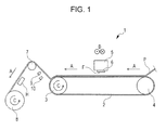
- Fig. 1 schematically illustrates a side surface of a recording apparatus 1 in an embodiment of the invention.
- the recording apparatus 1 in this embodiment includes: a driving roller 3 and a driven roller 4 that rotate in a rotation direction C.
- An adhesive belt 2 is tightly looped over the driving roller 3 and the driven roller 4 and supports a recording medium P while transporting it in a transport direction A.
- the adhesive belt 2 is tightly looped over a plurality of rotating bodies and supports and transports the recording medium P.
- the recording apparatus 1 in this embodiment is provided with two rollers, or the driving roller 3 and the driven roller 4, as the plurality of rotating bodies; however three or more rollers may be provided and some of these may be driving rollers.
- the term "adhesive belt” refers to a belt having a surface to which an adhesive is applied. A recording medium is supported by this surface while being detachably bonded thereto.
- a recording head 6 having an ink discharging section F from which an ink is discharged is provided on a path along which the adhesive belt 2 transports the recording medium P.
- the recording apparatus 1 discharges the ink onto the recording medium P through the ink discharging section F while the carriage 5 causes the recording head 6 to reciprocate in directions B perpendicular to the transport direction A, thereby creating desired images.
- the recording head 6 reciprocates to record images onto the recording medium P while the recording medium P stops being transported. Therefore, the adhesive belt 2 intermittently transports the recording medium P. More specifically, a recording process of discharging the ink onto the recording medium P through the ink discharging section F in the recording head 6 and a transporting process of transporting the recording medium P by moving the adhesive belt 2 by a preset amount are performed alternately. In short, the recording head 6 intermittently records images, and the adhesive belt 2 intermittently moves in turn.
- the above expression “intermittently moves” refers to a driving method of switching between the moving and stopped states of the adhesive belt 2. More specifically, in the moving state, the driving roller 3 is continuously driven until the adhesive belt 2 moves by a preset amount d; in the stopped state, the driving of the driving roller 3 is stopped such that the adhesive belt 2 stops for a predetermined period of time.
- the recording apparatus 1 in this embodiment is provided with the recording head 6 that reciprocates to record images; however it may be provided with a so-called line head having a plurality of nozzles from which inks are discharged, the nozzles being arranged in a direction perpendicular to the transport direction A.
- the term "line head” refers to a recording head used for a recording apparatus that creates images by fixing one of a recording head and a recording medium and moving the other.
- the line head has a nozzle region that extends in the direction perpendicular to the transport direction A of the recording medium P and covers the whole length of the recording medium P in this perpendicular direction.
- this nozzle region does not necessarily have to cover the whole lengths of all the types of recording media P in the perpendicular direction which the recording apparatus supports. If a recording apparatus is provided with a line head as described above, it can continuously transport a recording medium P by using an adhesive belt 2.
- the recording medium P is separated from the adhesive belt 2 within a predetermined range, then passes over a driven roller 7 fixed at a preset location and is wound around a take-up section 8, as will be described later. While winding the recording medium P, the take-up section 8 is rotating in the rotation direction C.
- the take-up section 8 is controlled by a controller 11, which will be described later, in such a way that it rotates at an angular velocity 1. Assuming that the angular velocity 1 of the take-up section 8 is constant, as the roll diameter of the take-up section 8 increases with the winding of the recording medium P, the take-up section 8 winds the recording medium P at a higher speed. Therefore, the constant angular velocity 1 of the take-up section 8 is set to a small value. Consequently, the take-up section 8 can be implemented by a low capacity motor. However, in an initial state where a small amount of recording medium P is wound around the take-up section 8 and therefore the roll diameter is small, the take-up section 8 winds the recording medium P at a low speed.
- a heater H is provided between the take-up section 8 and the driven roller 7; the heater H heats and dries images that have been created in the recording medium P through the discharge of the ink.
- the created images are naturally dried after the ink discharging section F has discharged the ink and before the image reaches the heater H, and then thermally dried by passing through the heating region of the heater H. After the images have been naturally and thermally dried in this manner, the recording medium P with the images is wound around the take-up section 8.
- a first sensor 9 and a second sensor 10 are installed on the transport path of the recording medium P and between the location at which the recording medium P is separated from the adhesive belt 2 and the location of the driven roller 7.
- Each of the first sensor 9 and the second sensor 10 is an optical sensor that can detect the relative location of the recording medium P by irradiating a surface of the recording medium P with light at a right angle and receiving the light reflected from this surface. Based on the respective detected locations of the recording medium P relative to the locations of the first sensor 9 and the second sensor 10, the location at which the recording medium P is separated from the adhesive belt 2 can be pinpointed. Using this method can detect the location more accurately than using any other relevant method.
- An exemplary relevant method uses: an irradiation source; a reflective material disposed opposite the irradiation source; and an optical sensor that receives light to be reflected by the reflective material. Further, the irradiation source irradiates a surface of the recording medium P with light traveling in a direction along the surface and then the optical sensor detects that the reflected light is blocked by the recording medium P, recognizing that the recording medium P is separated from the adhesive belt 2.
- Such relevant methods are prone to cause detection failures, because the length (thickness) of the recording medium P in a direction perpendicular to the surface of recording medium P is short and the detection timing for the optical sensor may not accordingly coincide with the timing at which the reflected light is blocked by the recording medium P.
- Fig. 2 is a block diagram illustrating the recording apparatus 1 in this embodiment.
- the controller 11 includes a CPU 12 that takes control over the recording apparatus 1.
- the CPU 12 is connected to both a ROM 14 that stores, for example, various control programs and maintenance sequences to be executed by the CPU 12 and a RAM 15 that temporarily stores data via a system bus 13.
- the CPU 12 is connected to a head driver 16 via the system bus 13; the head driver 16 drives the recording head 6.
- the CPU 12 is connected to a motor driver 17 via the system bus 13.
- the motor driver 17 drives: a carriage motor 18 that moves the carriage 5; a transport motor 19 that is a driving source for the driving roller 3 that acts as a moving mechanism for the adhesive belt 2 supporting and transporting the recording medium P; and a winding motor 20 that is a driving source for the take-up section 8.
- the CPU 12 is connected to a heater driver 23 via the system bus 13; the heater driver 23 operates the heater H to heat and dry images created in the recording medium P.
- the CPU 12 is connected to an I/O section 21 via the system bus 13.
- the I/O section 21 is connected to the first sensor 9, the second sensor 10 and a PC 22; the PC 22 is an external device through which data to be recorded and the like are input to the recording apparatus 1.
- the PC 22 is provided with a GUI (graphical user interface) 24.
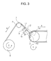
- FIGS. 3 to 5 are enlarged views each illustrating the main section of the recording apparatus 1 in this embodiment.
- the first sensor 9 detects whether or not the recording medium P is present (whether it receives light reflected from a surface of the recording medium P) within a detection range having a length L1.
- the first sensor 9 can thereby detect whether or not a separation location 25 at which the recording medium P is separated from the adhesive belt 2 is within a first range R1.
- the first sensor 9 can detect that the recording medium P is separated from the adhesive belt 2 within the first range R1.
- the second sensor 10 detects whether or not the recording medium P is present (whether it receives light reflected from the surface of the recording medium P) within a detection range having a length L2.
- the second sensor 10 can thereby detect whether or not the separation location 25 at which the recording medium P is separated from the adhesive belt 2 is within a second range R2 contained in the first range R1. In other words, the second sensor 10 can detect that the recording medium P is separated from the adhesive belt 2 within the second range R2 contained in the first range R1.
- the separation location 25 of the recording medium P is within the first range R1 but outside the second range R2.
- the separation location 25 of the recording medium P is outside the first range R1 (i.e., outside the second range R2).
- the separation location 25 of the recording medium P is within both the first range R1 and the second range R2.
- the state of Fig. 4 arises when the speed at which the take-up section 8 winds the recording medium P continues to be higher than the speed at which the adhesive belt 2 transports the recording medium P or when the take-up section 8 continues to wind the recording medium P while the adhesive belt 2 stops moving.
- the state of Fig. 5 arises when the speed at which the take-up section 8 winds the recording medium P continues to be lower than the speed at which the adhesive belt 2 transports the recording medium P or the adhesive belt 2 continues to move while the take-up section 8 stops winding the recording medium P.
- the controller 11 controls the take-up section 8 to wind the recording medium P.
- the separation location 25 of the recording medium P is within the first range R1
- the take-up section 8 is winding the recording medium P in the rotation direction C under the control of the controller 11.
- the separation location 25 of the recording medium P is outside the first range R1.
- the take-up section 8 stops winding the recording medium P, and the driving roller 3 is intermittently driven in the rotation direction C in accordance with the intermittent recording performed by the recording head 6.
- the controller 11 has a first mode, which will be described with reference to Fig. 6 .
- the controller 11 switches between a moving state and stopped state of the adhesive belt 2, based on information from the second sensor 10 so that the recording medium P is separated from the adhesive belt 2 within the second range R2, thereby controlling an average feed speed VA of the adhesive belt 2 to a constant average feed speed VC.
- the take-up section 8 continues to wind the recording medium P independently of the state of the adhesive belt 2. In other words, the recording medium P is continuously wound by the take-up section 8 even when the adhesive belt 2 stops moving.
- the average feed speed VA of the adhesive belt 2 is controlled to the constant average feed speed VC, it is possible to prevent an occurrence of an entanglement error in the adhesive belt 2 and feed the recording medium P to the downstream side at the constant average feed speed VC.
- the above control makes it possible to cause the ink discharging section F to record an image onto the recording medium P and feed the recording medium P to, for example, the heater H provided upstream of the take-up section 8 at regular time intervals. This can reduce a variation in a drying time for a recorded image, thus printing images with high quality.
- the moving speed VB and moving time tB of the adhesive belt 2 are set to constant values such that the driving roller 3 can feed the adhesive belt 2 by the preset amount d with a single movement, the preset amount d being determined in accordance with the intermittent recording performed by the recording head 6. Therefore, varying a stop time period t0 for the intermittently moving adhesive belt 2 can adjust the average feed speed VA of the adhesive belt 2. The shorter the stop time period t0, the higher the average feed speed VA. In other words, the longer the stop time period t0, the lower the average feed speed VA. If the stop time period t0 is set to a constant value, the average feed speed VA of the adhesive belt 2 becomes constant.
- the maximum average feed speed Vmax of the adhesive belt 2 is set such that it can conform to the winding speed of the take-up section 8 with a large diameter.
- the stop time period t0 becomes a time period tmin. If the controller 11 does not perform the control, the adhesive belt 2 intermittently moves at the maximum average feed speed Vmax.
- controller 11 controls the average feed speed VA of the adhesive belt 2 to the constant average feed speed VC by switching between the moving and stopped states of the adhesive belt 2 based on information from the second sensor 10 so that the recording medium P is separated from the adhesive belt 2 within the second range R2.
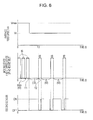
- Fig. 6 shows a relationship of: the average feed speed of the adhesive belt 2 (upper graph); the moving and stopped states of the adhesive belt 2 (middle graph); and the detection result of the second sensor (lower part), when the control is performed in the first mode.
- the controller 11 does not perform the control, and therefore the adhesive belt 2 intermittently moves at the maximum average feed speed Vmax, namely, under the condition of the stop time period t0 being the time period tmin.
- the recording apparatus 1 starts recording images, for example, if the take-up section 8 remains a core nearly and the take-up section 8 accordingly winds the recording medium P at a low speed, the feed amount of the adhesive belt 2 is greater than the winding amount of the take-up section 8. In this case, if the recording apparatus 1 continues to record images, the separation location 25 of the recording medium P enters the second range R2. In Fig. 5 , the separation location 25 of the recording medium P is within the second range R2, and the driving roller 3 stops rotating under the control of the controller 11 such that the adhesive belt 2 stops moving.
- the controller 11 controls the driving roller 3 in such a way that the adhesive belt 2 stops moving. In this case, the adhesive belt 2 stops moving at the timing when the driving roller 3 is not driven during the intermittent driving.
- a time T1 indicates when the second sensor 10 first detects the separation location 25 after the recording apparatus 1 has started recording images.
- the controller 11 starts the control in the first mode. In the lower part of Fig. 6 , the state where the second sensor 10 detects the separation location 25 is denoted by ON; the state where the second sensor 10 does not detect the separation location 25 is denoted by OFF.
- the second sensor 10 When the adhesive belt 2 enters the stopped state, only the take-up section 8 rotates to wind the recording medium P. Then, when the separation location 25 moves to the outside of the second range R2 (see Fig. 3 ), the second sensor 10 enters a non-detection state (OFF) where the separation location 25 is not detected. In response to this, the adhesive belt 2 starts moving, namely, enters the moving state.
- the time T2 (see the graph at the middle of Fig. 6 ) indicates when the second sensor 10 does not detect the separation location 25 and the adhesive belt 2 thereby resumes moving.
- the period over which the adhesive belt 2 stays in the stopped state, or the difference between the time T2 and the time Tl, is referred to as a stop time period t1.
- the stop time period t0 in the intermittent driving, over which the adhesive belt 2 stays in the stopped state is set to the stop time period t1.
- the average feed speed VA of the adhesive belt can be controlled to the constant average feed speed VC so that the recording medium P is separated from the adhesive belt 2 within the second range R2.
- the stop time period t1 is a time period that enables the detection state of the second sensor 10 to be switched from ON to OFF when the take-up section 8 winds the recording medium P at a winding speed V1, the winding speed V1 being the initial speed upon the recording of images in the first mode.
- the constant average feed speed VC of the adhesive belt 2 can be made to conform to the winding speed V1 of the take-up section 8 which has been initially set in the first mode.
- the average feed speed VC can be made substantially the same as the winding speed V1.
- the constant average feed speed VC of the adhesive belt 2 is desirably the same as the winding speed V1 of the take-up section 8 which has been initially set in the first mode. Note that the constant average feed speed VC of the adhesive belt 2 may be not only exactly the same as but also substantially the same as the winding speed V1 of the take-up section 8.
- the radius r1 of the take-up section 8 can be determined based on information regarding the total amount of recording medium P wound around the take-up section 8 and the thickness of the recording medium P.
- a sensor that detects the radius r1 of the take-up section 8 or a speed sensor that directly measures the winding speed V1 may be installed in the take-up section 8.
- the stop time period t0 may be set longer than the stop time period t1.
- the longer the stop time period the lower the average feed speed VC.
- the winding speed V1 becomes higher than the constant average feed speed VC. Therefore, it is possible to reliably prevent the recording medium P from being entangled in the adhesive belt 2.
- the constant average feed speed VC of the adhesive belt 2 may be set by a user to an arbitrary value that is equal to or less than the winding speed V1 of the take-up section 8 which has been initially set in the first mode.
- the winding speed of the take-up section 8 gradually increases.
- the second sensor 10 enters the off state during the stopped state of the adhesive belt 2, as shown in the lower graph of Fig. 6 .
- the separation location 25 of the recording medium P moves to the outside of the second range R2 but within the first range R1, because the winding speed of the take-up section 8 gradually increases during the first mode.
- the stop time period t0 may be set to a constant value without performing a process of acquiring the stop time period t1.
- the ROM 14 may store, in advance, data regarding the relationship between the total amount of the recording medium P wound around the take-up section 8 and the stop time period t1. Then, the stop time period t1 that would be acquired upon starting the control in the first mode may be determined from the total amount of the recording medium P stored in the PC 22, and then a constant value may be determined based on this stop time period t1.
- the control in the first mode may start in response to a user's instruction. In this case, the instruction is given, for example, by pressing a start button displayed in the GUI 24.
- the control in the first mode is terminated whenever one image is recorded.
- the termination may be made in response to a user's instruction.
- the instruction is given, for example, by pressing a termination button displayed in the GUI 24.
- the control in the first mode may be terminated when the total length of images recorded exceeds a preset length.
- the roll diameter of the take-up section 8 increases with the recording of images, its winding speed increasingly becomes higher than the winding speed V1 initially set in the first mode. Since the average feed speed of the adhesive belt 2 is controlled to the constant average feed speed VC, the winding speed of the take-up section 8 exceeds the average feed speed VC with the recoding of images, in which case the separation location 25 of the recording medium P moves to the outside of the first range R1.
- the first sensor 9 detects it whereby the take-up section 8 stops rotating.
- the moving speed of the adhesive belt 2 is still controlled to the constant average feed speed VC.
- an image recorded in the recording medium P reaches the heater H provided upstream of the take-up section 8 at regular time intervals whereby a variation in a drying time for recorded images is reduced.
- the average feed speed may be reset to a higher speed by, for example, keeping the rotation of the take-up section 8 without stopping it.
- the control in the first mode can be set in advance such that it is terminated before the winding speed of the take-up section 8 becomes so fast that the separation location 25 of the recording medium P moves to the outside of the first range R1.
- the recording apparatus 1 When not performing the control in the above first mode, the recording apparatus 1 records images in the second mode that will be described below.
- the second mode if the second sensor 10 detects the separation location 25 of the recording medium P within the second range R2, the adhesive belt 2 stops moving. If the second sensor 10 detects the separation location 25 of the recording medium P outside the second range R2, the adhesive belt 2 starts moving. These operations are repeated.
- Fig. 7 shows a relationship of: the average feed speed of the adhesive belt 2; the moving and stopped states of the adhesive belt 2; and the detection result of the second sensor.
- the control in the second mode starts when the take-up section 8 remains a core nearly, or has a small diameter.
- the roll diameter of the take-up section 8 increases with the recording of images, and the winding speed at which the take-up section 8 winds the recording medium P thereby increases.
- the time interval between when the adhesive belt 2 stops moving and when it starts moving decreases, as shown in the graph at the middle of Fig. 7 .
- the stop time period of the adhesive belt decreases.
- the stop time period of the adhesive belt 2 the higher the average feed speed VA of the adhesive belt 2 (see the graph in the upper part of Fig. 7 ).
- the stop time period of the adhesive belt 2 becomes a time period tmin, in which case the average feed speed VA of the adhesive belt 2 reaches the moving speed Vmax thereof.
- the average feed speed VA of the adhesive belt 2 increases.
- the average feed speed VA of the adhesive belt 2 increases in proportion to the increase in the winding speed of the take-up section 8. It is thus possible to record images with great productivity.
- a recording apparatus 1 in this embodiment is provided with a recording head 6 that reciprocates in directions B perpendicular to a transport direction A of a recording medium P, thereby recording images onto a recording medium P, as described above.
- a controller 11 controls a driving roller 3 to be intermittently driven in accordance with the reciprocating movement. If a second sensor 10 detects a separation location 25 of the recording medium P within a second range R2 in the course of the recording with the recording head 6, the controller 11 desirably controls a movement mechanism for the recording head 6 which includes a carriage motor 18 to move the recording head 6 to a home position after the recording of an image by the recording head 6, which accompanies one directional recording movement in the reciprocating movement, has been completed.
- the recording of an image which accompanies one directional recording movement in the reciprocating movement can be completely done. This can prevent a defective image from being recorded, thereby protecting images that have ever been recorded and also protect the recording head 6 at the home position.
- a recording apparatus 1 in this embodiment is provided with a recording head 6 that reciprocates in directions B perpendicular to a transport direction A of a recording medium P, thereby recording images onto a recording medium P, as described above.
- a controller 11 controls a driving roller 3 to be intermittently driven in accordance with the reciprocating movement. Further, before the driving of the driving roller 3 which is accompanied by the intermittent driving, the controller 11 controls a second sensor 10 to detect whether or not a separation location 25 of a recording medium P is within a second range R2. If the separation location 25 of the recording medium P is within the second range R2, the controller 11 controls the driving roller 3 to maintain the adhesive belt 2 in the stopped state.
- the controller 11 desirably controls the driving roller 3 to drive the driving roller 3 in accordance with the driving timing of the driving roller 3 which is accompanied by the intermittent driving.
- the second sensor 10 detects whether or not the separation location 25 of the recording medium P is within the second range R2 while the adhesive belt 2 is in the stopped state. This can prevent an occurrence of a defective recording operation, for example, by blocking the adhesive belt 2 from stopping at a halfway position.
Landscapes
- Handling Of Sheets (AREA)
- Ink Jet (AREA)
Abstract
Description
- The present invention relates to a recording apparatus and a recording method.
- In the past, recording apparatuses which include a plurality of rotating bodies, an adhesive belt and a take-up section have been used. The adhesive belt is tightly looped over the rotating bodies and holds a recording medium while transporting it; the take-up section winds the recording medium. Some of such disclosed recording apparatuses further include a sensor that detects a location at which a recording medium is separated from an adhesive belt.
-
JP-A-2007-196625 - The above recording apparatus is equipped with a mechanism for decreasing the drying time for recorded images, which greatly influences their qualities.
-
JP-A-10-331078 - In a recording apparatus as described above, when the speed at which the adhesive belt transports a recording medium is higher than the speed at which the take-up section winds the recording medium, the recording medium may become entangled in the adhesive belt. In other words, an entanglement error may occur.
- The roll diameter of the take-up section is initially the same as that of its roll core and then gradually increases with the winding of the recording medium. Assuming that the winding motor in the take-up section rotates at a regular speed, when its roll diameter is small, the winding speed of the recording medium is relatively low. Therefore, a recording apparatus that continuously transports a recording medium by using the adhesive belt, like that described in
JP-A-2007-196625 - On the other hand, the provision of a sensor can prevent an occurrence of an entanglement error even if the take-up section winds a recording medium at a low speed. More specifically, the sensor detects the separation location of the recording medium, and the adhesive belt stops transporting the recording medium when a risk that the recording medium will become entangled in the adhesive belt increases. With this configuration, a small capacity winding motor can be used for the take-up section, and the need to rotate the winding motor at a high speed can be eliminated. Here, the configuration that causes a sensor to detect the separation location of a recording medium and prevents an occurrence of an entanglement error by stopping a running adhesive belt is abbreviated below as "entanglement error prevention measures."
- Suppose the winding motor rotates at a regular speed, or at a regular angular velocity. When the roll diameter of the take-up section is small, the take-up section winds a recording medium at a low speed. However, as the roll diameter increases with the winding of the recording medium, the take-up section winds the recording medium at a higher speed. If the aforementioned "entanglement error prevention measures" are applied to the configuration in which the speed at which the take-up section winds the recording medium gradually increases, disadvantages that will be described below may arise.
- When the roll diameter of the take-up section is small, the take-up section winds the recording medium at a lower speed than that at which the adhesive belt transports the recording medium. Therefore, the recording medium becomes entangled in the adhesive belt. In response to this, a sensor detects that the recording medium is entangled in the adhesive belt, and the adhesive belt stops running. In the meantime, the take-up section winds the recording medium, thereby eliminating the entanglement of the recording medium. However, since the take-up section winds the recording medium at a low speed as described above, it takes a long time to wind the recording medium, and the adhesive belt stops running for a long time.
- The take-up section winds the recording medium at a higher speed as the roll diameter of the take-up section increases. Therefore, even if the sensor detects the entanglement of the recording medium and the adhesive belt stops being driven, the adhesive belt does not stop for a long time.
- An average speed (also referred to below as an "average feed speed") at which the adhesive belt transports the recording medium decreases as the stop time period of the adhesive belt increases. In other words, the average speed increases as the stop time period of the adhesive belt decreases. Thus, as the roll diameter increases with the winding of the recording medium in the take-up section, the winding speed of the take-up section gradually increases. In response, the average feed speed of the adhesive belt also increases with the varying winding speed.
- When a recording apparatus that includes an adhesive belt and a take-up section records an image onto a recording medium over the adhesive belt, it typically subjects the image to a drying process by using a drying section provided upstream from the location at which the recording medium will be wound around the take-up section. When the roll diameter of the take-up section increases, the winding speed and average feed speed of the adhesive belt increases and therefore times and decrease. Here, the time represents a time required to transport an image recorded onto the recording medium to the drying section; the time represents a time required to pass an image recorded onto the recording medium through the drying section.
- Therefore, while a recording apparatus is transporting the recording medium by using the adhesive belt and is recording images onto the recording medium, the drying time for the recorded images, which corresponds to the sum of the times and , is gradually decreasing. Such a variation in the drying time (+) may develop unevenness in the recorded images.
- An advantage of some aspects of the invention is to provide a recording apparatus which includes: an adhesive belt that supports and transports a recording medium; and a take-up section that winds the recording medium enables a low capacity winding motor to be used for the take-up section but can prevent an occurrence of an entanglement error in the adhesive belt and print images with a high quality.
- A recording apparatus according to a first aspect of the invention includes: an adhesive belt that supports and transports a recording medium and is looped over a plurality of rotating bodies; a recording head that records an image onto the recording medium; a first sensor that detects that the recording medium is separated from the adhesive belt within a first range; a second sensor that detects that the recording medium is separated from the adhesive belt within a second range contained in the first range; a take-up section that winds the recording medium; and a controller that controls a rotation of the take-up section and a movement of the adhesive belt. The controller is configured to transport the recording medium at an average feed speed while rotating the take-up section at a constant angular velocity and switching between a moving state and stopped state of the adhesive belt. In addition, the controller has a first mode of controlling the average feed speed to a constant average feed speed by switching between the moving state and the stopped state, based on information from the second sensor so that the recording medium is separated within the second range.
- Herein, the term "adhesive belt" refers to a belt having a surface to which an adhesive is applied. A recording medium is supported by this surface while being detachably bonded thereto.
- The controller has a first mode of controlling the average feed speed to a constant average feed speed by switching between the moving state and the stopped state, based on information from the second sensor so that the recording medium is separated within the second range.
- According to the first aspect, the average feed speed is controlled to the constant average feed speed so that the recording medium is separated from the second range positioned downstream of the adhesive belt and upstream of the take-up section. This makes it possible to feed the recording medium at the constant average feed speed to the downstream side while preventing an occurrence of an entanglement error in the adhesive belt, thus printing images with high quality.
- The controller preferably controls the average feed speed to the constant average feed speed by controlling a stop time period of the adhesive belt.
- Controlling a stop time period of the adhesive belt in order to control the average feed speed to the constant average feed speed can produce substantially the same effect as the first aspect.
- The first mode preferably starts when the second sensor initially detects the separation location within the second range.
- The average feed speed of the adhesive belt in the first mode is preferably the same as a winding speed initially set in the first mode.
- The average feed speed of the adhesive belt in the first mode can be preferably set lower than a winding speed initially set in the first mode.
- The controller preferably has a second mode of repeatedly stopping a movement of the adhesive belt if the second sensor detects a separation location of the recording medium within the second range and starting the movement of the adhesive belt if the second sensor detects the separation location of the recording medium outside the second range.
- Proving the second mode can record images with great productivity.
- A recording method according to a second aspect of the invention includes: transporting a recording medium supported on the adhesive belt looped over a plurality of rotating bodies; recording an image onto the recording medium by using a recording head; detecting that the recording medium is separated from the adhesive belt within a first range by using a first sensor; detecting that the recording medium is separated from the adhesive belt within a second range contained in the first range by using a second sensor; winding the recording medium by using a take-up section; transporting the recording medium at an average feed speed while rotating the take-up section at a constant angular velocity and switching between a moving state and stopped state of the adhesive belt; and executing a first mode of controlling the average feed speed to a constant average feed speed by switching between the moving state and the stopped state, based on information from the second sensor so that the recording medium is separated within the second range.
- The second aspect can produce substantially the same effect as the first aspect.
- Embodiments of the invention will now be described by way of example only with reference to the accompanying drawings, wherein like numbers reference like elements.
-
Fig. 1 schematically illustrates a side surface of a recording apparatus in an embodiment of the invention. -
Fig. 2 is a block diagram illustrating the recording apparatus. -
Fig. 3 is an enlarged view illustrating the main section of the recording apparatus. -
Fig. 4 is another enlarged view illustrating the main section of the recording apparatus. -
Fig. 5 is further another enlarged view illustrating the main section of the recording apparatus. -
Fig. 6 shows a relationship of: the average feed speed of the adhesive belt; the moving and stopped states of the adhesive belt; and the detection result of the second sensor, in a first mode. -
Fig. 7 shows a relationship of: the average feed speed of the adhesive belt; the moving and stopped states of the adhesive belt; and the detection result of the second sensor, in a second mode. - A recording apparatus in an embodiment of the invention will be described below with reference to the accompanying drawings. It should be noted that the invention is not limited to the embodiment and drawings.
-
Fig. 1 schematically illustrates a side surface of arecording apparatus 1 in an embodiment of the invention. Therecording apparatus 1 in this embodiment includes: a drivingroller 3 and a drivenroller 4 that rotate in a rotation direction C. Anadhesive belt 2 is tightly looped over the drivingroller 3 and the drivenroller 4 and supports a recording medium P while transporting it in a transport direction A. In other words, theadhesive belt 2 is tightly looped over a plurality of rotating bodies and supports and transports the recording medium P. Therecording apparatus 1 in this embodiment is provided with two rollers, or the drivingroller 3 and the drivenroller 4, as the plurality of rotating bodies; however three or more rollers may be provided and some of these may be driving rollers. Herein, the term "adhesive belt" refers to a belt having a surface to which an adhesive is applied. A recording medium is supported by this surface while being detachably bonded thereto. - A
recording head 6 having an ink discharging section F from which an ink is discharged is provided on a path along which theadhesive belt 2 transports the recording medium P. Therecording apparatus 1 discharges the ink onto the recording medium P through the ink discharging section F while thecarriage 5 causes therecording head 6 to reciprocate in directions B perpendicular to the transport direction A, thereby creating desired images. - The
recording head 6 reciprocates to record images onto the recording medium P while the recording medium P stops being transported. Therefore, theadhesive belt 2 intermittently transports the recording medium P. More specifically, a recording process of discharging the ink onto the recording medium P through the ink discharging section F in therecording head 6 and a transporting process of transporting the recording medium P by moving theadhesive belt 2 by a preset amount are performed alternately. In short, therecording head 6 intermittently records images, and theadhesive belt 2 intermittently moves in turn. - The above expression "intermittently moves" refers to a driving method of switching between the moving and stopped states of the
adhesive belt 2. More specifically, in the moving state, the drivingroller 3 is continuously driven until theadhesive belt 2 moves by a preset amount d; in the stopped state, the driving of the drivingroller 3 is stopped such that theadhesive belt 2 stops for a predetermined period of time. - The
recording apparatus 1 in this embodiment is provided with therecording head 6 that reciprocates to record images; however it may be provided with a so-called line head having a plurality of nozzles from which inks are discharged, the nozzles being arranged in a direction perpendicular to the transport direction A. The term "line head" refers to a recording head used for a recording apparatus that creates images by fixing one of a recording head and a recording medium and moving the other. The line head has a nozzle region that extends in the direction perpendicular to the transport direction A of the recording medium P and covers the whole length of the recording medium P in this perpendicular direction. Note that this nozzle region does not necessarily have to cover the whole lengths of all the types of recording media P in the perpendicular direction which the recording apparatus supports. If a recording apparatus is provided with a line head as described above, it can continuously transport a recording medium P by using anadhesive belt 2. - In the
recording apparatus 1 in this embodiment, the recording medium P is separated from theadhesive belt 2 within a predetermined range, then passes over a drivenroller 7 fixed at a preset location and is wound around a take-upsection 8, as will be described later. While winding the recording medium P, the take-upsection 8 is rotating in the rotation direction C. - The take-up
section 8 is controlled by acontroller 11, which will be described later, in such a way that it rotates at anangular velocity 1. Assuming that theangular velocity 1 of the take-upsection 8 is constant, as the roll diameter of the take-upsection 8 increases with the winding of the recording medium P, the take-upsection 8 winds the recording medium P at a higher speed. Therefore, the constantangular velocity 1 of the take-upsection 8 is set to a small value. Consequently, the take-upsection 8 can be implemented by a low capacity motor. However, in an initial state where a small amount of recording medium P is wound around the take-upsection 8 and therefore the roll diameter is small, the take-upsection 8 winds the recording medium P at a low speed. - A heater H is provided between the take-up
section 8 and the drivenroller 7; the heater H heats and dries images that have been created in the recording medium P through the discharge of the ink. The created images are naturally dried after the ink discharging section F has discharged the ink and before the image reaches the heater H, and then thermally dried by passing through the heating region of the heater H. After the images have been naturally and thermally dried in this manner, the recording medium P with the images is wound around the take-upsection 8. - A
first sensor 9 and asecond sensor 10 are installed on the transport path of the recording medium P and between the location at which the recording medium P is separated from theadhesive belt 2 and the location of the drivenroller 7. Each of thefirst sensor 9 and thesecond sensor 10 is an optical sensor that can detect the relative location of the recording medium P by irradiating a surface of the recording medium P with light at a right angle and receiving the light reflected from this surface. Based on the respective detected locations of the recording medium P relative to the locations of thefirst sensor 9 and thesecond sensor 10, the location at which the recording medium P is separated from theadhesive belt 2 can be pinpointed. Using this method can detect the location more accurately than using any other relevant method. An exemplary relevant method uses: an irradiation source; a reflective material disposed opposite the irradiation source; and an optical sensor that receives light to be reflected by the reflective material. Further, the irradiation source irradiates a surface of the recording medium P with light traveling in a direction along the surface and then the optical sensor detects that the reflected light is blocked by the recording medium P, recognizing that the recording medium P is separated from theadhesive belt 2. Such relevant methods are prone to cause detection failures, because the length (thickness) of the recording medium P in a direction perpendicular to the surface of recording medium P is short and the detection timing for the optical sensor may not accordingly coincide with the timing at which the reflected light is blocked by the recording medium P. - Next, a description will be given of an electrical configuration of the
recording apparatus 1 in this embodiment.Fig. 2 is a block diagram illustrating therecording apparatus 1 in this embodiment. Thecontroller 11 includes aCPU 12 that takes control over therecording apparatus 1. TheCPU 12 is connected to both aROM 14 that stores, for example, various control programs and maintenance sequences to be executed by theCPU 12 and aRAM 15 that temporarily stores data via asystem bus 13. - The
CPU 12 is connected to ahead driver 16 via thesystem bus 13; thehead driver 16 drives therecording head 6. TheCPU 12 is connected to amotor driver 17 via thesystem bus 13. Themotor driver 17 drives: acarriage motor 18 that moves thecarriage 5; atransport motor 19 that is a driving source for the drivingroller 3 that acts as a moving mechanism for theadhesive belt 2 supporting and transporting the recording medium P; and a windingmotor 20 that is a driving source for the take-upsection 8. TheCPU 12 is connected to aheater driver 23 via thesystem bus 13; theheater driver 23 operates the heater H to heat and dry images created in the recording medium P. TheCPU 12 is connected to an I/O section 21 via thesystem bus 13. The I/O section 21 is connected to thefirst sensor 9, thesecond sensor 10 and aPC 22; thePC 22 is an external device through which data to be recorded and the like are input to therecording apparatus 1. ThePC 22 is provided with a GUI (graphical user interface) 24. - Next, a more detailed description will be given with reference to an enlarged view of the main section in the
recording apparatus 1.Figs. 3 to 5 are enlarged views each illustrating the main section of therecording apparatus 1 in this embodiment. - As illustrated in
Figs. 3 to 5 , thefirst sensor 9 detects whether or not the recording medium P is present (whether it receives light reflected from a surface of the recording medium P) within a detection range having a length L1. Thefirst sensor 9 can thereby detect whether or not aseparation location 25 at which the recording medium P is separated from theadhesive belt 2 is within a first range R1. In other words, thefirst sensor 9 can detect that the recording medium P is separated from theadhesive belt 2 within the first range R1. In addition, thesecond sensor 10 detects whether or not the recording medium P is present (whether it receives light reflected from the surface of the recording medium P) within a detection range having a length L2. Thesecond sensor 10 can thereby detect whether or not theseparation location 25 at which the recording medium P is separated from theadhesive belt 2 is within a second range R2 contained in the first range R1. In other words, thesecond sensor 10 can detect that the recording medium P is separated from theadhesive belt 2 within the second range R2 contained in the first range R1. - In
Fig. 3 , theseparation location 25 of the recording medium P is within the first range R1 but outside the second range R2. InFig. 4 , theseparation location 25 of the recording medium P is outside the first range R1 (i.e., outside the second range R2). InFig. 5 , theseparation location 25 of the recording medium P is within both the first range R1 and the second range R2. Specifically, viewing the state inFig. 3 as a reference, the state ofFig. 4 arises when the speed at which the take-upsection 8 winds the recording medium P continues to be higher than the speed at which theadhesive belt 2 transports the recording medium P or when the take-upsection 8 continues to wind the recording medium P while theadhesive belt 2 stops moving. The state ofFig. 5 arises when the speed at which the take-upsection 8 winds the recording medium P continues to be lower than the speed at which theadhesive belt 2 transports the recording medium P or theadhesive belt 2 continues to move while the take-upsection 8 stops winding the recording medium P. - If the
first sensor 9 detects theseparation location 25 of the recording medium P within the first range R1, thecontroller 11 controls the take-upsection 8 to wind the recording medium P. In the states ofFigs. 3 and5 , theseparation location 25 of the recording medium P is within the first range R1, and the take-upsection 8 is winding the recording medium P in the rotation direction C under the control of thecontroller 11. In the state ofFig. 4 , theseparation location 25 of the recording medium P is outside the first range R1. In this case, under the control of thecontroller 11, the take-upsection 8 stops winding the recording medium P, and the drivingroller 3 is intermittently driven in the rotation direction C in accordance with the intermittent recording performed by therecording head 6. - The
controller 11 has a first mode, which will be described with reference toFig. 6 . In the first mode, thecontroller 11 switches between a moving state and stopped state of theadhesive belt 2, based on information from thesecond sensor 10 so that the recording medium P is separated from theadhesive belt 2 within the second range R2, thereby controlling an average feed speed VA of theadhesive belt 2 to a constant average feed speed VC. - When the recording medium P is transported while the
adhesive belt 2 is switched between the moving and stopped states, the take-upsection 8 continues to wind the recording medium P independently of the state of theadhesive belt 2. In other words, the recording medium P is continuously wound by the take-upsection 8 even when theadhesive belt 2 stops moving. - The average feed speed VA of the
adhesive belt 2 is controlled to the constant average feed speed VC, it is possible to prevent an occurrence of an entanglement error in theadhesive belt 2 and feed the recording medium P to the downstream side at the constant average feed speed VC. - The above control makes it possible to cause the ink discharging section F to record an image onto the recording medium P and feed the recording medium P to, for example, the heater H provided upstream of the take-up
section 8 at regular time intervals. This can reduce a variation in a drying time for a recorded image, thus printing images with high quality. - According to the
recording apparatus 1 in this embodiment, in the moving state where theadhesive belt 2 is intermittently driven, the moving speed VB and moving time tB of theadhesive belt 2 are set to constant values such that the drivingroller 3 can feed theadhesive belt 2 by the preset amount d with a single movement, the preset amount d being determined in accordance with the intermittent recording performed by therecording head 6. Therefore, varying a stop time period t0 for the intermittently movingadhesive belt 2 can adjust the average feed speed VA of theadhesive belt 2. The shorter the stop time period t0, the higher the average feed speed VA. In other words, the longer the stop time period t0, the lower the average feed speed VA. If the stop time period t0 is set to a constant value, the average feed speed VA of theadhesive belt 2 becomes constant. - While the take-up
section 8 is winding the recording medium P during the recording, its winding speed gradually increases. Therefore, the maximum average feed speed Vmax of theadhesive belt 2 is set such that it can conform to the winding speed of the take-upsection 8 with a large diameter. When the average feed speed VA reaches the maximum average feed speed Vmax, the stop time period t0 becomes a time period tmin. If thecontroller 11 does not perform the control, theadhesive belt 2 intermittently moves at the maximum average feed speed Vmax. - Next, a more detailed description will be given of a configuration in which the
controller 11 controls the average feed speed VA of theadhesive belt 2 to the constant average feed speed VC by switching between the moving and stopped states of theadhesive belt 2 based on information from thesecond sensor 10 so that the recording medium P is separated from theadhesive belt 2 within the second range R2. -
Fig. 6 shows a relationship of: the average feed speed of the adhesive belt 2 (upper graph); the moving and stopped states of the adhesive belt 2 (middle graph); and the detection result of the second sensor (lower part), when the control is performed in the first mode. First, suppose theseparation location 25 of the recording medium P is within the first range R1 but outside the second range R2 when the recording of images starts. In addition, thecontroller 11 does not perform the control, and therefore theadhesive belt 2 intermittently moves at the maximum average feed speed Vmax, namely, under the condition of the stop time period t0 being the time period tmin. - When the
recording apparatus 1 starts recording images, for example, if the take-upsection 8 remains a core nearly and the take-upsection 8 accordingly winds the recording medium P at a low speed, the feed amount of theadhesive belt 2 is greater than the winding amount of the take-upsection 8. In this case, if therecording apparatus 1 continues to record images, theseparation location 25 of the recording medium P enters the second range R2. InFig. 5 , theseparation location 25 of the recording medium P is within the second range R2, and the drivingroller 3 stops rotating under the control of thecontroller 11 such that theadhesive belt 2 stops moving. - If the
second sensor 10 detects theseparation location 25, thecontroller 11 controls the drivingroller 3 in such a way that theadhesive belt 2 stops moving. In this case, theadhesive belt 2 stops moving at the timing when the drivingroller 3 is not driven during the intermittent driving. A time T1 indicates when thesecond sensor 10 first detects theseparation location 25 after therecording apparatus 1 has started recording images. In this embodiment, when thesecond sensor 10 first detects the recording medium P after the recording of images has started, thecontroller 11 starts the control in the first mode. In the lower part ofFig. 6 , the state where thesecond sensor 10 detects theseparation location 25 is denoted by ON; the state where thesecond sensor 10 does not detect theseparation location 25 is denoted by OFF. - When the
adhesive belt 2 enters the stopped state, only the take-upsection 8 rotates to wind the recording medium P. Then, when theseparation location 25 moves to the outside of the second range R2 (seeFig. 3 ), thesecond sensor 10 enters a non-detection state (OFF) where theseparation location 25 is not detected. In response to this, theadhesive belt 2 starts moving, namely, enters the moving state. The time T2 (see the graph at the middle ofFig. 6 ) indicates when thesecond sensor 10 does not detect theseparation location 25 and theadhesive belt 2 thereby resumes moving. The period over which theadhesive belt 2 stays in the stopped state, or the difference between the time T2 and the time Tl, is referred to as a stop time period t1. - After the stop time period t1 is acquired, or after the time T2, the stop time period t0 in the intermittent driving, over which the
adhesive belt 2 stays in the stopped state, is set to the stop time period t1. In this way, the average feed speed VA of the adhesive belt can be controlled to the constant average feed speed VC so that the recording medium P is separated from theadhesive belt 2 within the second range R2. - The stop time period t1 is a time period that enables the detection state of the
second sensor 10 to be switched from ON to OFF when the take-upsection 8 winds the recording medium P at a winding speed V1, the winding speed V1 being the initial speed upon the recording of images in the first mode. By setting the stop time period t0 to the stop time period t1, the constant average feed speed VC of theadhesive belt 2 can be made to conform to the winding speed V1 of the take-upsection 8 which has been initially set in the first mode. In other words, the average feed speed VC can be made substantially the same as the winding speed V1. - The constant average feed speed VC of the
adhesive belt 2 is desirably the same as the winding speed V1 of the take-upsection 8 which has been initially set in the first mode. Note that the constant average feed speed VC of theadhesive belt 2 may be not only exactly the same as but also substantially the same as the winding speed V1 of the take-upsection 8. - The winding speed V1 of the take-up
section 8 can also be determined from the radius r1 of the take-up section 8 (V1= r1 · 1). Here, the radius r1 of the take-upsection 8 can be determined based on information regarding the total amount of recording medium P wound around the take-upsection 8 and the thickness of the recording medium P. Alternatively, a sensor that detects the radius r1 of the take-upsection 8 or a speed sensor that directly measures the winding speed V1 may be installed in the take-upsection 8. - Alternatively, the stop time period t0 may be set longer than the stop time period t1. The longer the stop time period, the lower the average feed speed VC. In this case, the winding speed V1 becomes higher than the constant average feed speed VC. Therefore, it is possible to reliably prevent the recording medium P from being entangled in the
adhesive belt 2. The constant average feed speed VC of theadhesive belt 2 may be set by a user to an arbitrary value that is equal to or less than the winding speed V1 of the take-upsection 8 which has been initially set in the first mode. - When the recording medium P is transported at a constant speed while the
adhesive belt 2 is switched between the moving and stopped states under the condition of the stop time period t0 being the time period t1, the winding speed of the take-upsection 8 gradually increases. As a result, thesecond sensor 10 enters the off state during the stopped state of theadhesive belt 2, as shown in the lower graph ofFig. 6 . In the first mode, however, the stopped state of theadhesive belt 2 which continues for the stop time period t0 (= t1) is prioritized. Furthermore, when theadhesive belt 2 continues to transport theadhesive belt 2 at the constant average feed speed VC that has been initially set in the first mode, theseparation location 25 of the recording medium P moves to the outside of the second range R2 but within the first range R1, because the winding speed of the take-upsection 8 gradually increases during the first mode. - Before the control in the first mode is performed, the stop time period t0 may be set to a constant value without performing a process of acquiring the stop time period t1. For example, the
ROM 14 may store, in advance, data regarding the relationship between the total amount of the recording medium P wound around the take-upsection 8 and the stop time period t1. Then, the stop time period t1 that would be acquired upon starting the control in the first mode may be determined from the total amount of the recording medium P stored in thePC 22, and then a constant value may be determined based on this stop time period t1. The control in the first mode may start in response to a user's instruction. In this case, the instruction is given, for example, by pressing a start button displayed in theGUI 24. - The control in the first mode is terminated whenever one image is recorded. Alternatively, the termination may be made in response to a user's instruction. In this case, the instruction is given, for example, by pressing a termination button displayed in the
GUI 24. - The control in the first mode may be terminated when the total length of images recorded exceeds a preset length. As the roll diameter of the take-up
section 8 increases with the recording of images, its winding speed increasingly becomes higher than the winding speed V1 initially set in the first mode. Since the average feed speed of theadhesive belt 2 is controlled to the constant average feed speed VC, the winding speed of the take-upsection 8 exceeds the average feed speed VC with the recoding of images, in which case theseparation location 25 of the recording medium P moves to the outside of the first range R1. When theseparation location 25 of the recording medium P moves to the outside of the first range R1, thefirst sensor 9 detects it whereby the take-upsection 8 stops rotating. In this case, even if the recording of images is further continued, the moving speed of theadhesive belt 2 is still controlled to the constant average feed speed VC. As a result, an image recorded in the recording medium P reaches the heater H provided upstream of the take-upsection 8 at regular time intervals whereby a variation in a drying time for recorded images is reduced. However, the average feed speed may be reset to a higher speed by, for example, keeping the rotation of the take-upsection 8 without stopping it. In this way, the control in the first mode can be set in advance such that it is terminated before the winding speed of the take-upsection 8 becomes so fast that theseparation location 25 of the recording medium P moves to the outside of the first range R1. - When not performing the control in the above first mode, the
recording apparatus 1 records images in the second mode that will be described below. In the second mode, if thesecond sensor 10 detects theseparation location 25 of the recording medium P within the second range R2, theadhesive belt 2 stops moving. If thesecond sensor 10 detects theseparation location 25 of the recording medium P outside the second range R2, theadhesive belt 2 starts moving. These operations are repeated.Fig. 7 shows a relationship of: the average feed speed of theadhesive belt 2; the moving and stopped states of theadhesive belt 2; and the detection result of the second sensor. - Suppose the control in the second mode starts when the take-up
section 8 remains a core nearly, or has a small diameter. The roll diameter of the take-upsection 8 increases with the recording of images, and the winding speed at which the take-upsection 8 winds the recording medium P thereby increases. As a result, every time theadhesive belt 2 moves and stops based on the detection result of thesecond sensor 10, the time interval between when theadhesive belt 2 stops moving and when it starts moving decreases, as shown in the graph at the middle ofFig. 7 . In other words, the stop time period of the adhesive belt decreases. Here, the following relationship is satisfied: - t1 > t2 > t3 > t4 > t5.
In the graph in the lower part ofFig. 7 , the state where thesecond sensor 10 detects theseparation location 25 is denoted by ON; the state where thesecond sensor 10 does not detect theseparation location 25 is denoted by OFF. - The shorter the stop time period of the
adhesive belt 2, the higher the average feed speed VA of the adhesive belt 2 (see the graph in the upper part ofFig. 7 ). When the roll diameter of the take-upsection 8 sufficiently increases, the stop time period of theadhesive belt 2 becomes a time period tmin, in which case the average feed speed VA of theadhesive belt 2 reaches the moving speed Vmax thereof. - In the second mode, as described above, as the winding speed at which the take-up
section 8 winds the recording medium P increases, the average feed speed VA of theadhesive belt 2 increases. Under the control in the second mode, the average feed speed VA of theadhesive belt 2 increases in proportion to the increase in the winding speed of the take-upsection 8. It is thus possible to record images with great productivity. - A
recording apparatus 1 in this embodiment is provided with arecording head 6 that reciprocates in directions B perpendicular to a transport direction A of a recording medium P, thereby recording images onto a recording medium P, as described above. Acontroller 11 controls a drivingroller 3 to be intermittently driven in accordance with the reciprocating movement. If asecond sensor 10 detects aseparation location 25 of the recording medium P within a second range R2 in the course of the recording with therecording head 6, thecontroller 11 desirably controls a movement mechanism for therecording head 6 which includes acarriage motor 18 to move therecording head 6 to a home position after the recording of an image by therecording head 6, which accompanies one directional recording movement in the reciprocating movement, has been completed. With the control performed by thecontroller 11 in this manner, the recording of an image which accompanies one directional recording movement in the reciprocating movement can be completely done. This can prevent a defective image from being recorded, thereby protecting images that have ever been recorded and also protect therecording head 6 at the home position. - A
recording apparatus 1 in this embodiment is provided with arecording head 6 that reciprocates in directions B perpendicular to a transport direction A of a recording medium P, thereby recording images onto a recording medium P, as described above. Acontroller 11 controls a drivingroller 3 to be intermittently driven in accordance with the reciprocating movement. Further, before the driving of the drivingroller 3 which is accompanied by the intermittent driving, thecontroller 11 controls asecond sensor 10 to detect whether or not aseparation location 25 of a recording medium P is within a second range R2. If theseparation location 25 of the recording medium P is within the second range R2, thecontroller 11 controls the drivingroller 3 to maintain theadhesive belt 2 in the stopped state. If theseparation location 25 of the recording medium P is not within the second range R2, thecontroller 11 desirably controls the drivingroller 3 to drive the drivingroller 3 in accordance with the driving timing of the drivingroller 3 which is accompanied by the intermittent driving. Under the control performed in this manner by thecontroller 11, thesecond sensor 10 detects whether or not theseparation location 25 of the recording medium P is within the second range R2 while theadhesive belt 2 is in the stopped state. This can prevent an occurrence of a defective recording operation, for example, by blocking theadhesive belt 2 from stopping at a halfway position. - The invention is not limited to the embodiment described above; it will be appreciated that various modifications are possible within the scope of the invention described in the claims and these modifications fall within the scope of the invention.
Claims (7)
- A recording apparatus (1) comprising:an adhesive belt (2) for supporting and transporting a recording medium (P), the adhesive belt being looped over a plurality of rotating bodies (3, 4);a recording head (6) for recording an image onto the recording medium;a first sensor (9) for detecting that the recording medium is separated from the adhesive belt within a first range (R1);a second sensor (10) for detecting that the recording medium is separated from the adhesive belt within a second range (R2) contained in the first range;a take-up section (8) for winding the recording medium; anda controller (11) for controlling a rotation of the take-up section and a movement of the adhesive belt,the controller configured to transport the recording medium at an average feed speed while rotating the take-up section at a constant angular velocity and switching between a moving state and stopped state of the adhesive belt,the controller having a first mode of controlling the average feed speed to a constant average feed speed by switching between the moving state and the stopped state, based on information from the second sensor so that the recording medium is separated within the second range.
- The recording apparatus according to Claim 1, wherein
the controller is configured to control the average feed speed to the constant average feed speed by controlling a stop time period of the adhesive belt. - The recording apparatus according to Claim 1 or Claim 2 is configured to
the first mode when the second sensor initially detects the separation location within the second range. - The recording apparatus according to any one of the preceding claims, wherein
the average feed speed of the adhesive belt in the first mode is the same as a winding speed initially set in the first mode. - The recording apparatus according to any one of Claims 1 to 3, wherein
the average feed speed of the adhesive belt in the first mode can be set lower than a winding speed initially set in the first mode. - The recording apparatus according to any one of the preceding claims, wherein
the controller has a second mode of repeatedly stopping a movement of the adhesive belt if the second sensor detects a separation location of the recording medium within the second range and starting the movement of the adhesive belt if the second sensor detects the separation location of the recording medium outside the second range. - A recording method comprising:transporting a recording medium (P) supported on an adhesive belt (2), the adhesive belt being looped over a plurality of rotating bodies (3,4);recording an image onto the recording medium by using a recording head (6);detecting that the recording medium is separated from the adhesive belt within a first range (R1) by using a first sensor (9);detecting that the recording medium is separated from the adhesive belt within a second range (R2) contained in the first range by using a second sensor (10);winding the recording medium by using a take-up section (8);transporting the recording medium at an average feed speed while rotating the take-up section at a constant angular velocity and switching between a moving state and stopped state of the adhesive belt; andexecuting a first mode of controlling the average feed speed to a constant average feed speed by switching between the moving state and the stopped state, based on information from the second sensor so that the recording medium is separated within the second range.
Applications Claiming Priority (1)
| Application Number | Priority Date | Filing Date | Title |
|---|---|---|---|
| JP2014028246A JP6244966B2 (en) | 2014-02-18 | 2014-02-18 | Recording apparatus and recording method |
Publications (2)
| Publication Number | Publication Date |
|---|---|
| EP2933212A1 true EP2933212A1 (en) | 2015-10-21 |
| EP2933212B1 EP2933212B1 (en) | 2016-12-14 |
Family
ID=52574041
Family Applications (1)
| Application Number | Title | Priority Date | Filing Date |
|---|---|---|---|
| EP15155474.8A Active EP2933212B1 (en) | 2014-02-18 | 2015-02-17 | Recording apparatus and method |
Country Status (2)
| Country | Link |
|---|---|
| EP (1) | EP2933212B1 (en) |
| JP (1) | JP6244966B2 (en) |
Cited By (3)
| Publication number | Priority date | Publication date | Assignee | Title |
|---|---|---|---|---|
| CN106183440A (en) * | 2016-08-30 | 2016-12-07 | 厦门汉印电子技术有限公司 | The portable printer of a kind of anti-carbon ribbon abjection and method |
| EP2857335B1 (en) * | 2013-09-17 | 2019-07-03 | Seiko Epson Corporation | Recording apparatus and recording method |
| EP4613495A4 (en) * | 2023-03-29 | 2026-02-25 | Kyocera Corp | PRINTING DEVICE, PRINTING SYSTEM AND PRINTING PROCESS |
Citations (3)
| Publication number | Priority date | Publication date | Assignee | Title |
|---|---|---|---|---|
| JPH10331078A (en) | 1997-06-02 | 1998-12-15 | Canon Inc | Ink jet dyeing fabric, ink jet dyeing method and ink jet dye using the same |
| JP2006321611A (en) * | 2005-05-18 | 2006-11-30 | Konica Minolta Holdings Inc | Winding device, and printer using the same |
| JP2007196625A (en) | 2006-01-30 | 2007-08-09 | Konica Minolta Holdings Inc | Inkjet recording device |
Family Cites Families (4)
| Publication number | Priority date | Publication date | Assignee | Title |
|---|---|---|---|---|
| JP3168118B2 (en) * | 1994-07-21 | 2001-05-21 | キヤノン株式会社 | Image forming device |
| JP3590887B2 (en) * | 2000-12-28 | 2004-11-17 | 株式会社イチノセインターナショナル | Transfer angle changing device for cloth to be dyed |
| JP5410875B2 (en) * | 2009-07-30 | 2014-02-05 | セーレン株式会社 | Inkjet recording apparatus and inkjet recording method |
| JP2013001062A (en) * | 2011-06-21 | 2013-01-07 | Seiko Epson Corp | Recording apparatus, and recording method |
-
2014
- 2014-02-18 JP JP2014028246A patent/JP6244966B2/en not_active Expired - Fee Related
-
2015
- 2015-02-17 EP EP15155474.8A patent/EP2933212B1/en active Active
Patent Citations (3)
| Publication number | Priority date | Publication date | Assignee | Title |
|---|---|---|---|---|
| JPH10331078A (en) | 1997-06-02 | 1998-12-15 | Canon Inc | Ink jet dyeing fabric, ink jet dyeing method and ink jet dye using the same |
| JP2006321611A (en) * | 2005-05-18 | 2006-11-30 | Konica Minolta Holdings Inc | Winding device, and printer using the same |
| JP2007196625A (en) | 2006-01-30 | 2007-08-09 | Konica Minolta Holdings Inc | Inkjet recording device |
Cited By (4)
| Publication number | Priority date | Publication date | Assignee | Title |
|---|---|---|---|---|
| EP2857335B1 (en) * | 2013-09-17 | 2019-07-03 | Seiko Epson Corporation | Recording apparatus and recording method |
| CN106183440A (en) * | 2016-08-30 | 2016-12-07 | 厦门汉印电子技术有限公司 | The portable printer of a kind of anti-carbon ribbon abjection and method |
| CN106183440B (en) * | 2016-08-30 | 2018-05-04 | 厦门汉印电子技术有限公司 | A kind of portable printer and method of anti-carbon ribbon abjection |
| EP4613495A4 (en) * | 2023-03-29 | 2026-02-25 | Kyocera Corp | PRINTING DEVICE, PRINTING SYSTEM AND PRINTING PROCESS |
Also Published As
| Publication number | Publication date |
|---|---|
| EP2933212B1 (en) | 2016-12-14 |
| JP6244966B2 (en) | 2017-12-13 |
| JP2015150821A (en) | 2015-08-24 |
Similar Documents
| Publication | Publication Date | Title |
|---|---|---|
| US10328728B2 (en) | Image recording apparatus and image recording method for printing each of a plurality of unit images | |
| US9555649B2 (en) | Image recording apparatus and image recording method | |
| US20150225196A1 (en) | Recording apparatus and winding method | |
| JP6337538B2 (en) | Image recording apparatus, calibration method, and image recording method | |
| US10308059B2 (en) | Printing apparatus and control method for printing apparatus | |
| CN108621602B (en) | Printing method | |
| EP2933212B1 (en) | Recording apparatus and method | |
| US9248667B2 (en) | Method to operate an inkjet printer with at least two printing stations, and inkjet printer with two printing stations | |
| US9844959B2 (en) | Recording device | |
| US9724939B2 (en) | Liquid discharging apparatus | |
| JP5605046B2 (en) | Image recording apparatus and image recording method | |
| US10201984B2 (en) | Printing system | |
| JP6962137B2 (en) | Recording device | |
| JP5884499B2 (en) | Conveying apparatus, conveying method, and image recording apparatus | |
| JP6213723B2 (en) | Recording apparatus and recording method | |
| US9333774B2 (en) | Recording apparatus, method for transporting recording medium, and method for notifying information of remaining amount of recording medium | |
| CN105102232B (en) | inkjet recording device | |
| CN108883633B (en) | Ink jet recording apparatus and recording control method for ink jet recording apparatus | |
| JP2015117123A (en) | Mark detection method and printer | |
| JP2015182245A (en) | Printing apparatus and printing method | |
| US11628676B2 (en) | Recording device and recording method | |
| JP7484584B2 (en) | MEDIUM HEATING DEVICE AND LIQUID DISCHARGE DEVICE | |
| CN103085499A (en) | Image recording device,image recording method | |
| EP2754563B1 (en) | Recording apparatus and recording method |
Legal Events
| Date | Code | Title | Description |
|---|---|---|---|
| PUAI | Public reference made under article 153(3) epc to a published international application that has entered the european phase |
Free format text: ORIGINAL CODE: 0009012 |
|
| AK | Designated contracting states |
Kind code of ref document: A1 Designated state(s): AL AT BE BG CH CY CZ DE DK EE ES FI FR GB GR HR HU IE IS IT LI LT LU LV MC MK MT NL NO PL PT RO RS SE SI SK SM TR |
|
| AX | Request for extension of the european patent |
Extension state: BA ME |
|
| 17P | Request for examination filed |
Effective date: 20160302 |
|
| RBV | Designated contracting states (corrected) |
Designated state(s): AL AT BE BG CH CY CZ DE DK EE ES FI FR GB GR HR HU IE IS IT LI LT LU LV MC MK MT NL NO PL PT RO RS SE SI SK SM TR |
|
| GRAP | Despatch of communication of intention to grant a patent |
Free format text: ORIGINAL CODE: EPIDOSNIGR1 |
|
| INTG | Intention to grant announced |
Effective date: 20160707 |
|
| RIC1 | Information provided on ipc code assigned before grant |
Ipc: B41J 11/00 20060101ALI20160624BHEP Ipc: B41J 15/04 20060101ALI20160624BHEP Ipc: B65H 23/195 20060101AFI20160624BHEP Ipc: B65H 23/188 20060101ALI20160624BHEP |
|
| GRAS | Grant fee paid |
Free format text: ORIGINAL CODE: EPIDOSNIGR3 |
|
| GRAA | (expected) grant |
Free format text: ORIGINAL CODE: 0009210 |
|
| AK | Designated contracting states |
Kind code of ref document: B1 Designated state(s): AL AT BE BG CH CY CZ DE DK EE ES FI FR GB GR HR HU IE IS IT LI LT LU LV MC MK MT NL NO PL PT RO RS SE SI SK SM TR |
|
| REG | Reference to a national code |
Ref country code: GB Ref legal event code: FG4D |
|
| REG | Reference to a national code |
Ref country code: CH Ref legal event code: EP |
|
| REG | Reference to a national code |
Ref country code: IE Ref legal event code: FG4D |
|
| REG | Reference to a national code |
Ref country code: AT Ref legal event code: REF Ref document number: 853356 Country of ref document: AT Kind code of ref document: T Effective date: 20170115 |
|
| REG | Reference to a national code |
Ref country code: DE Ref legal event code: R096 Ref document number: 602015000956 Country of ref document: DE |
|
| REG | Reference to a national code |
Ref country code: FR Ref legal event code: PLFP Year of fee payment: 3 |
|
| PG25 | Lapsed in a contracting state [announced via postgrant information from national office to epo] |
Ref country code: LV Free format text: LAPSE BECAUSE OF FAILURE TO SUBMIT A TRANSLATION OF THE DESCRIPTION OR TO PAY THE FEE WITHIN THE PRESCRIBED TIME-LIMIT Effective date: 20161214 |
|
| REG | Reference to a national code |
Ref country code: LT Ref legal event code: MG4D |
|
| REG | Reference to a national code |
Ref country code: NL Ref legal event code: MP Effective date: 20161214 |
|
| PG25 | Lapsed in a contracting state [announced via postgrant information from national office to epo] |
Ref country code: LT Free format text: LAPSE BECAUSE OF FAILURE TO SUBMIT A TRANSLATION OF THE DESCRIPTION OR TO PAY THE FEE WITHIN THE PRESCRIBED TIME-LIMIT Effective date: 20161214 Ref country code: NO Free format text: LAPSE BECAUSE OF FAILURE TO SUBMIT A TRANSLATION OF THE DESCRIPTION OR TO PAY THE FEE WITHIN THE PRESCRIBED TIME-LIMIT Effective date: 20170314 Ref country code: SE Free format text: LAPSE BECAUSE OF FAILURE TO SUBMIT A TRANSLATION OF THE DESCRIPTION OR TO PAY THE FEE WITHIN THE PRESCRIBED TIME-LIMIT Effective date: 20161214 Ref country code: GR Free format text: LAPSE BECAUSE OF FAILURE TO SUBMIT A TRANSLATION OF THE DESCRIPTION OR TO PAY THE FEE WITHIN THE PRESCRIBED TIME-LIMIT Effective date: 20170315 |
|
| REG | Reference to a national code |
Ref country code: AT Ref legal event code: MK05 Ref document number: 853356 Country of ref document: AT Kind code of ref document: T Effective date: 20161214 |
|
| PG25 | Lapsed in a contracting state [announced via postgrant information from national office to epo] |
Ref country code: BE Free format text: LAPSE BECAUSE OF NON-PAYMENT OF DUE FEES Effective date: 20170228 Ref country code: RS Free format text: LAPSE BECAUSE OF FAILURE TO SUBMIT A TRANSLATION OF THE DESCRIPTION OR TO PAY THE FEE WITHIN THE PRESCRIBED TIME-LIMIT Effective date: 20161214 Ref country code: HR Free format text: LAPSE BECAUSE OF FAILURE TO SUBMIT A TRANSLATION OF THE DESCRIPTION OR TO PAY THE FEE WITHIN THE PRESCRIBED TIME-LIMIT Effective date: 20161214 Ref country code: FI Free format text: LAPSE BECAUSE OF FAILURE TO SUBMIT A TRANSLATION OF THE DESCRIPTION OR TO PAY THE FEE WITHIN THE PRESCRIBED TIME-LIMIT Effective date: 20161214 |
|
| PG25 | Lapsed in a contracting state [announced via postgrant information from national office to epo] |
Ref country code: NL Free format text: LAPSE BECAUSE OF FAILURE TO SUBMIT A TRANSLATION OF THE DESCRIPTION OR TO PAY THE FEE WITHIN THE PRESCRIBED TIME-LIMIT Effective date: 20161214 |
|
| PG25 | Lapsed in a contracting state [announced via postgrant information from national office to epo] |
Ref country code: CZ Free format text: LAPSE BECAUSE OF FAILURE TO SUBMIT A TRANSLATION OF THE DESCRIPTION OR TO PAY THE FEE WITHIN THE PRESCRIBED TIME-LIMIT Effective date: 20161214 Ref country code: IS Free format text: LAPSE BECAUSE OF FAILURE TO SUBMIT A TRANSLATION OF THE DESCRIPTION OR TO PAY THE FEE WITHIN THE PRESCRIBED TIME-LIMIT Effective date: 20170414 Ref country code: RO Free format text: LAPSE BECAUSE OF FAILURE TO SUBMIT A TRANSLATION OF THE DESCRIPTION OR TO PAY THE FEE WITHIN THE PRESCRIBED TIME-LIMIT Effective date: 20161214 Ref country code: SK Free format text: LAPSE BECAUSE OF FAILURE TO SUBMIT A TRANSLATION OF THE DESCRIPTION OR TO PAY THE FEE WITHIN THE PRESCRIBED TIME-LIMIT Effective date: 20161214 Ref country code: EE Free format text: LAPSE BECAUSE OF FAILURE TO SUBMIT A TRANSLATION OF THE DESCRIPTION OR TO PAY THE FEE WITHIN THE PRESCRIBED TIME-LIMIT Effective date: 20161214 |
|
| PG25 | Lapsed in a contracting state [announced via postgrant information from national office to epo] |
Ref country code: BE Free format text: LAPSE BECAUSE OF FAILURE TO SUBMIT A TRANSLATION OF THE DESCRIPTION OR TO PAY THE FEE WITHIN THE PRESCRIBED TIME-LIMIT Effective date: 20161214 Ref country code: ES Free format text: LAPSE BECAUSE OF FAILURE TO SUBMIT A TRANSLATION OF THE DESCRIPTION OR TO PAY THE FEE WITHIN THE PRESCRIBED TIME-LIMIT Effective date: 20161214 Ref country code: PT Free format text: LAPSE BECAUSE OF FAILURE TO SUBMIT A TRANSLATION OF THE DESCRIPTION OR TO PAY THE FEE WITHIN THE PRESCRIBED TIME-LIMIT Effective date: 20170414 Ref country code: PL Free format text: LAPSE BECAUSE OF FAILURE TO SUBMIT A TRANSLATION OF THE DESCRIPTION OR TO PAY THE FEE WITHIN THE PRESCRIBED TIME-LIMIT Effective date: 20161214 Ref country code: BG Free format text: LAPSE BECAUSE OF FAILURE TO SUBMIT A TRANSLATION OF THE DESCRIPTION OR TO PAY THE FEE WITHIN THE PRESCRIBED TIME-LIMIT Effective date: 20170314 Ref country code: AT Free format text: LAPSE BECAUSE OF FAILURE TO SUBMIT A TRANSLATION OF THE DESCRIPTION OR TO PAY THE FEE WITHIN THE PRESCRIBED TIME-LIMIT Effective date: 20161214 Ref country code: SM Free format text: LAPSE BECAUSE OF FAILURE TO SUBMIT A TRANSLATION OF THE DESCRIPTION OR TO PAY THE FEE WITHIN THE PRESCRIBED TIME-LIMIT Effective date: 20161214 |
|
| REG | Reference to a national code |
Ref country code: DE Ref legal event code: R097 Ref document number: 602015000956 Country of ref document: DE |
|
| PG25 | Lapsed in a contracting state [announced via postgrant information from national office to epo] |
Ref country code: MC Free format text: LAPSE BECAUSE OF FAILURE TO SUBMIT A TRANSLATION OF THE DESCRIPTION OR TO PAY THE FEE WITHIN THE PRESCRIBED TIME-LIMIT Effective date: 20161214 |
|
| PLBE | No opposition filed within time limit |
Free format text: ORIGINAL CODE: 0009261 |
|
| STAA | Information on the status of an ep patent application or granted ep patent |
Free format text: STATUS: NO OPPOSITION FILED WITHIN TIME LIMIT |
|
| 26N | No opposition filed |
Effective date: 20170915 |
|
| REG | Reference to a national code |
Ref country code: IE Ref legal event code: MM4A |
|
| PG25 | Lapsed in a contracting state [announced via postgrant information from national office to epo] |
Ref country code: DK Free format text: LAPSE BECAUSE OF FAILURE TO SUBMIT A TRANSLATION OF THE DESCRIPTION OR TO PAY THE FEE WITHIN THE PRESCRIBED TIME-LIMIT Effective date: 20161214 |
|
| PG25 | Lapsed in a contracting state [announced via postgrant information from national office to epo] |
Ref country code: LU Free format text: LAPSE BECAUSE OF NON-PAYMENT OF DUE FEES Effective date: 20170217 |
|
| REG | Reference to a national code |
Ref country code: FR Ref legal event code: PLFP Year of fee payment: 4 |
|
| PG25 | Lapsed in a contracting state [announced via postgrant information from national office to epo] |
Ref country code: IE Free format text: LAPSE BECAUSE OF NON-PAYMENT OF DUE FEES Effective date: 20170217 Ref country code: SI Free format text: LAPSE BECAUSE OF FAILURE TO SUBMIT A TRANSLATION OF THE DESCRIPTION OR TO PAY THE FEE WITHIN THE PRESCRIBED TIME-LIMIT Effective date: 20161214 |
|
| REG | Reference to a national code |
Ref country code: CH Ref legal event code: PL |
|
| PG25 | Lapsed in a contracting state [announced via postgrant information from national office to epo] |
Ref country code: MT Free format text: LAPSE BECAUSE OF NON-PAYMENT OF DUE FEES Effective date: 20170217 |
|
| PG25 | Lapsed in a contracting state [announced via postgrant information from national office to epo] |
Ref country code: LI Free format text: LAPSE BECAUSE OF NON-PAYMENT OF DUE FEES Effective date: 20180228 Ref country code: CH Free format text: LAPSE BECAUSE OF NON-PAYMENT OF DUE FEES Effective date: 20180228 |
|
| PG25 | Lapsed in a contracting state [announced via postgrant information from national office to epo] |
Ref country code: HU Free format text: LAPSE BECAUSE OF FAILURE TO SUBMIT A TRANSLATION OF THE DESCRIPTION OR TO PAY THE FEE WITHIN THE PRESCRIBED TIME-LIMIT; INVALID AB INITIO Effective date: 20150217 |
|
| GBPC | Gb: european patent ceased through non-payment of renewal fee |
Effective date: 20190217 |
|
| PG25 | Lapsed in a contracting state [announced via postgrant information from national office to epo] |
Ref country code: CY Free format text: LAPSE BECAUSE OF FAILURE TO SUBMIT A TRANSLATION OF THE DESCRIPTION OR TO PAY THE FEE WITHIN THE PRESCRIBED TIME-LIMIT Effective date: 20161214 |
|
| PG25 | Lapsed in a contracting state [announced via postgrant information from national office to epo] |
Ref country code: MK Free format text: LAPSE BECAUSE OF FAILURE TO SUBMIT A TRANSLATION OF THE DESCRIPTION OR TO PAY THE FEE WITHIN THE PRESCRIBED TIME-LIMIT Effective date: 20161214 |
|
| PG25 | Lapsed in a contracting state [announced via postgrant information from national office to epo] |
Ref country code: GB Free format text: LAPSE BECAUSE OF NON-PAYMENT OF DUE FEES Effective date: 20190217 |
|
| PG25 | Lapsed in a contracting state [announced via postgrant information from national office to epo] |
Ref country code: AL Free format text: LAPSE BECAUSE OF FAILURE TO SUBMIT A TRANSLATION OF THE DESCRIPTION OR TO PAY THE FEE WITHIN THE PRESCRIBED TIME-LIMIT Effective date: 20161214 |
|
| PGFP | Annual fee paid to national office [announced via postgrant information from national office to epo] |
Ref country code: IT Payment date: 20210112 Year of fee payment: 7 Ref country code: FR Payment date: 20210113 Year of fee payment: 7 |
|
| PGFP | Annual fee paid to national office [announced via postgrant information from national office to epo] |
Ref country code: DE Payment date: 20210202 Year of fee payment: 7 Ref country code: TR Payment date: 20210216 Year of fee payment: 7 |
|
| REG | Reference to a national code |
Ref country code: DE Ref legal event code: R119 Ref document number: 602015000956 Country of ref document: DE |
|
| PG25 | Lapsed in a contracting state [announced via postgrant information from national office to epo] |
Ref country code: FR Free format text: LAPSE BECAUSE OF NON-PAYMENT OF DUE FEES Effective date: 20220228 |
|
| PG25 | Lapsed in a contracting state [announced via postgrant information from national office to epo] |
Ref country code: DE Free format text: LAPSE BECAUSE OF NON-PAYMENT OF DUE FEES Effective date: 20220901 |
|
| PG25 | Lapsed in a contracting state [announced via postgrant information from national office to epo] |
Ref country code: IT Free format text: LAPSE BECAUSE OF NON-PAYMENT OF DUE FEES Effective date: 20220217 |