EP2933170B1 - Manually operated fastener for the side boards of industrial vehicle bodies - Google Patents
Manually operated fastener for the side boards of industrial vehicle bodies Download PDFInfo
- Publication number
- EP2933170B1 EP2933170B1 EP15152384.2A EP15152384A EP2933170B1 EP 2933170 B1 EP2933170 B1 EP 2933170B1 EP 15152384 A EP15152384 A EP 15152384A EP 2933170 B1 EP2933170 B1 EP 2933170B1
- Authority
- EP
- European Patent Office
- Prior art keywords
- insert
- fastener
- side board
- containment casing
- fastener according
- Prior art date
- Legal status (The legal status is an assumption and is not a legal conclusion. Google has not performed a legal analysis and makes no representation as to the accuracy of the status listed.)
- Not-in-force
Links
- 239000002184 metal Substances 0.000 description 2
- 230000005484 gravity Effects 0.000 description 1
- 230000002427 irreversible effect Effects 0.000 description 1
- 238000012423 maintenance Methods 0.000 description 1
- 239000000463 material Substances 0.000 description 1
Images






Classifications
-
- B—PERFORMING OPERATIONS; TRANSPORTING
- B60—VEHICLES IN GENERAL
- B60J—WINDOWS, WINDSCREENS, NON-FIXED ROOFS, DOORS, OR SIMILAR DEVICES FOR VEHICLES; REMOVABLE EXTERNAL PROTECTIVE COVERINGS SPECIALLY ADAPTED FOR VEHICLES
- B60J5/00—Doors
- B60J5/04—Doors arranged at the vehicle sides
- B60J5/0497—Doors arranged at the vehicle sides for load transporting vehicles or public transport, e.g. lorries, trucks, buses
-
- B—PERFORMING OPERATIONS; TRANSPORTING
- B62—LAND VEHICLES FOR TRAVELLING OTHERWISE THAN ON RAILS
- B62D—MOTOR VEHICLES; TRAILERS
- B62D33/00—Superstructures for load-carrying vehicles
- B62D33/02—Platforms; Open load compartments
- B62D33/023—Sideboard or tailgate structures
- B62D33/027—Sideboard or tailgate structures movable
- B62D33/037—Latching means therefor
-
- E—FIXED CONSTRUCTIONS
- E05—LOCKS; KEYS; WINDOW OR DOOR FITTINGS; SAFES
- E05B—LOCKS; ACCESSORIES THEREFOR; HANDCUFFS
- E05B15/00—Other details of locks; Parts for engagement by bolts of fastening devices
- E05B15/0053—Other details of locks; Parts for engagement by bolts of fastening devices means providing a stable, i.e. indexed, position of lock parts
-
- E—FIXED CONSTRUCTIONS
- E05—LOCKS; KEYS; WINDOW OR DOOR FITTINGS; SAFES
- E05B—LOCKS; ACCESSORIES THEREFOR; HANDCUFFS
- E05B15/00—Other details of locks; Parts for engagement by bolts of fastening devices
- E05B15/0053—Other details of locks; Parts for engagement by bolts of fastening devices means providing a stable, i.e. indexed, position of lock parts
- E05B15/006—Spring-biased ball or roller entering a notch
-
- E—FIXED CONSTRUCTIONS
- E05—LOCKS; KEYS; WINDOW OR DOOR FITTINGS; SAFES
- E05C—BOLTS OR FASTENING DEVICES FOR WINGS, SPECIALLY FOR DOORS OR WINDOWS
- E05C1/00—Fastening devices with bolts moving rectilinearly
- E05C1/02—Fastening devices with bolts moving rectilinearly without latching action
- E05C1/04—Fastening devices with bolts moving rectilinearly without latching action with operating handle or equivalent member rigid with the bolt
-
- E—FIXED CONSTRUCTIONS
- E05—LOCKS; KEYS; WINDOW OR DOOR FITTINGS; SAFES
- E05B—LOCKS; ACCESSORIES THEREFOR; HANDCUFFS
- E05B13/00—Devices preventing the key or the handle or both from being used
- E05B13/10—Devices preventing the key or the handle or both from being used formed by a lock arranged in the handle
Definitions
- This invention relates to a manually operated fastener for the side boards of industrial vehicle bodies.
- this invention relates to a fastener of the type comprising a hollow containment casing, elongate along a vertical main axis of extension (at least when the side board is in the hooking/unhooking position), and inside which an insert is slidably mounted, a pin with an enlarged head being fixed to the insert.
- the pin is positioned perpendicularly to the main axis of extension and comes out of a lateral wall of the containment casing so that it can engage with and disengage from a containment pocket fixed to a different part of the vehicle body.
- the side board can be closed either by fixing the side board to an upright rigidly connected to the frame of the vehicle body, or by fixing the side board to another side board.
- the fastener is mounted on one of the two side boards and the pocket on the other. Hooking and unhooking are achieved by moving the insert inside the containment casing and thereby causing the pin to translate between an engaging position in which the head of the pin is inserted in the pocket and a disengaging position in which the head is outside the pocket.
- the movement of the insert may occur in other ways.
- a movement mechanism comprising an operating lever connected to the insert in such a way as to cause the translation of the insert by means of a rotation of the lever.
- the lever when the insert is in the locking position the lever is positioned parallel to the main axis of extension and is practically completely inserted in the containment casing. Moreover, in that position, the lever prevents the fastener from being accidentally released. In order to unhook the side board, the lever is then rotated outwards (upwards or downwards) and causes a translation of the insert.
- EP 2567882 discloses a vehicle body which comprises an openable side board and one hooking unit for locking the openable side board, where the looking unit in turn comprises a supporting body and a hooking element which is rotatably connected to a pin fixed to the supporting body and able to rotate between a locking position and a releasing position.
- the hooking element comprises a first, operating end, and a second end which in use can be hooked to a fixed contact element.
- the hooking element is also able to move, relative to the supporting body, orthogonally to the main axis of rotation, between an extended position and a retracted position.
- Elastic return means are interposed between the supporting body and the hooking element for pushing the hooking element towards the retracted position.
- the hooking element comprises a sealed housing rotatably and slidably associated with the pin, and in which the elastic return means are positioned.
- the technical purpose which forms the basis of this invention is to provide a manually operated fastener for the side boards of industrial vehicle bodies which overcomes the above-mentioned disadvantages.
- the technical purpose of this invention is to provide a manually operated fastener for the side boards of industrial vehicle bodies which minimises the risks to operators and which is simpler, and therefore less expensive, than prior art fasteners.
- the numeral 1 denotes in its entirety a manually operated fastener for the side boards of industrial vehicle bodies according to this invention.
- the fastener according to this invention comprises first a hollow containment casing 2 in which an insert 3 is slidably inserted.
- the containment casing 2 may be fixed either to a side board of an industrial vehicle body or to another part of the vehicle body to which the side board must be hooked. It should be noticed that similarly to what is indicated relative to the prior art, in the case of this invention too, the other part of the vehicle body to which the side board must be hooked may be either a part rigidly fixed to the frame (such as an upright) or another side board.
- the containment casing 2 also has a main axis of extension which, at least when the side board is closed, is positioned perpendicularly to the loading platform of the vehicle body.
- the containment casing 2 comprises a tubular body 4 (advantageously metal) with a substantially rectangular cross-section, having two larger sides and two smaller sides, closed by plugs 5 at the ends.
- the containment casing 2 also comprises a main opening 6, made in a first face 7 of it parallel to the main axis of extension which in use is facing outwards from the vehicle body, and a secondary opening 8 made in a second face 9 of it positioned transversally relative to the first face 7.
- the main opening 6 and the secondary opening 8 are made in the tubular body 4, respectively at one of the larger sides and one of the smaller sides of the rectangular cross-section.
- the insert 3 is slidably inserted in the containment casing 2, and is movable along the main axis of extension between a first position ( Figures 14 and 15 ) and a second position ( Figures 21 to 22 ).
- first position in use corresponds to side board locking
- second position in use corresponds to side board releasing.
- At least a first connecting element 10 is fixed to the insert 3 and is positioned at the secondary opening 8 both when the insert 3 is in the first position and when it is in the second position. That first connecting element 10 in use is hookable to a second connecting element 11 which is respectively fixed to the other part of the vehicle body or to the side board.
- the two connecting elements 10, 11 are constituted, one of a pin with an enlarged head, and the other of a pocket in which the enlarged head of the pin is hookable (in the known way the pocket comprises a U-shaped flange in which the pin engages).
- the first connecting element 10 is constituted of the pin and is screwed into a tubular seat 12 made in the insert 3 and extending perpendicular to the main axis of extension.
- the insert 3 comprises a movement recess 13 accessible through the main opening 6 both when the insert 3 is in the first position and when the insert 3 is in the second position, and by means of which the insert 3 can be moved between the first position and the second position.
- the insert 3 is delimited by a first wall 14 and a second wall 15 which are positioned transversally to the main axis of extension and on which the user can act to cause shifting of the insert 3 between the first position and the second position.
- the user pushes on the first wall 14 to cause shifting of the insert 3 towards the first position and on the second wall 15 to cause shifting of the insert 3 towards the second position.
- the first wall 14 and the second wall 15 are stepped, concave with the concavities facing each other, and converge with one another towards the inside of the recess 13. Whilst in the preferred embodiments the entire recess 13 is always completely facing the main opening 6 irrespective of whether or not the insert 3 is in the first position, in the second position or in an intermediate position, in other embodiments it is sufficient that when the insert 3 is in the first position the second wall 15 is accessible and that when the insert 3 is in the second position the first wall 14 is accessible.
- the fastener 1 also comprises a selective locking unit 16 which is associated with the insert 3 and is switchable, at least when the insert 3 is in the first position, between a locking position in which it prevents the insert 3 from sliding towards the second position, and a releasing position in which allows insert 3 sliding towards the second position.
- the function of the selective locking unit 16 is to prevent the side board from being accidentally unhooked.
- the selective locking unit 16 comprises an engagement element 17 connected respectively either to the insert 3 or to the containment casing 2 and engageable respectively either with the containment casing 2 or with the insert 3 when the insert 3 is in the first position and the selective locking unit 16 is in the locking position.
- the fastener 1 also comprises elastic means 18 which act on the engagement element 17 for pushing it towards the locking position.
- the engagement element 17 is connected to the insert 3 and, when the insert 3 is in the first position and the selective locking unit 16 is in the locking position, the engagement element 17 is accessible through the main opening 6 and is engaged with an edge 19 of the main opening 6 extending transversally to the main axis of extension.
- the engagement element 17 can be switched from the locking position to the releasing position by a pressure applied directly on it.
- the engagement element 17 is constituted of a projecting tooth fixed to the insert 3 ( Figures 1 and 3 ).
- the insert 3 comprises a locking portion 20 which is deformable or shiftable relative to the rest of the insert 3, and to which the engagement element 17 is connected.
- the switching of the engagement element 17 from the locking position to the releasing position occurs by deformation or shifting of the locking portion 20 relative to the rest of the insert 3.
- the locking portion 20 is elastically deformable relative to the rest of the insert 3 and is part of, or constitutes, the elastic means 18.
- the elastic means 18 may be constituted exclusively of the elastic deformability of the locking portion 20 or may also comprise one or more springs which act on the locking portion 20.
- two springs could be inserted in the two first housings 21 made on the side of the locking portion 20 opposite that where the engagement element 17 is made.
- the insert 3 comprises two cantilever portions 20, 22 extending mainly parallel to the main axis of extension, facing one another and spaced from each other.
- One of these portions is the locking portion 20 and has a reduced thickness at the zone 23 where it is connected to the rest of the insert 3 for increasing its deformability ( Figure 4 ).
- the other 22 can act as a fixed contact element for any springs (in fact, the above-mentioned first housings 21 are also present in that cantilever portion) or as a guide for sliding of the insert 3 inside the containment casing 2.
- the overall dimensions of the fastener 1 always substantially correspond only to those of the containment casing 2 (see Figures 15 and 22 ).
- the insert 3 whatever position the insert 3 is in, there are no parts of the fastener 1 projecting from the main opening 6 except for the engagement element 17.
- the only part which, if present, has to project relative to the containment casing 2 is in fact the pin with the enlarged head.
- the insert 3 and the selective locking unit 16 are made in one piece.
- a finishing element 24 may also be applied to the insert 3.
- the finishing element is only shown in Figures 10 and 11 , being constituted of a customisable plate (the accompanying drawings show, by way of example only, the text "OPEN” to indicate that when that text is visible the fastener 1 is released, and similarly the text "CLOSE” directly on the insert 3 which, when visible, indicates that the fastener 1 is in the locking configuration).
- On the back of the finishing element there are three irreversible hooking heads 25 insertable in corresponding holes 26 made in the insert 3.
- the finishing element 24 also has a safety function.
- the finishing element 24 is positioned on the insert 3 in such a way that it is at least partly facing the main opening 6 when the insert is not in the first position and in contrast is completely not facing the main opening 6 and is therefore hidden from view when the insert 3 is in the first position.
- the finishing element 24 in a different colour to the insert 3, it is possible to visually show the operator when the fastener is not completely closed.
- the operator can see the colour of the finishing element 24, he knows that the fastener is still not correctly closed.
- the same result may also be achieved in other ways, such as that shown by way of example in Figure 26 and described in detail below.
- Figures 26 to 30 show a second embodiment of this invention which differs from the first exclusively as regards the structure of the insert 3 and of the elastic means 18. Consequently, for greater clarity, in Figures 26 to 30 many parts corresponding to those of the preceding figures are not shown.
- the engagement element 17 is connected to the insert 3.
- the elastic means 18 are positioned between the insert 3 and the containment casing 2 for pushing the engagement element 17 towards the locking position at least when the insert 3 is in the first position. That is in particular advantageously achieved thanks to the fact that the elastic means 18 act between the insert 3 and an inner surface 30 of the containment casing opposite to the wall in which the main opening 6 is made.
- the elastic means 18 comprise one or more first springs 31, advantageously helical springs, associated with the insert 3 and, for each first spring 31, at least one element for contact 32 interposed between the related first spring 31 and the above-mentioned inner surface 30 of the containment casing 2.
- Each element for contact 32 is positioned in such a way that it slides on the inner surface 30 of the containment casing 2 during the shifting movements of the insert 3 between the first position and the second position.
- each element for contact 32 is constituted of a metal sphere or half-sphere.
- the insert 3 pivots about an axis of rotation passing through the first connecting element 10 and the secondary opening 8 (the axis of rotation is advantageously defined by the cooperation between the pin which constitutes the first connecting element 10 and the slot which constitutes the secondary opening 8).
- the switching of the engagement element 17 between the locking position ( Figure 28 ) and the releasing position ( Figure 29 ) therefore occurs by means of a rotation of the insert 3 about said axis of rotation.
- the rotation occurs by overcoming the opposition of the elastic means 18, whilst when going in the opposite direction it is driven by the elastic means 18.
- SAFE text 34
- the insert 3 is equipped with selective engaging means 35 couplable to suitable second housings 36 made in the containment casing 2 when the insert 3 is respectively in the first position (with the selective locking unit 17 in the locking position) and in the second position.
- the selecting engaging means 35 comprise a second helical spring 37 positioned in such a way that it passes through the insert 3 and is perpendicular to its line of movement. At its ends, said spring pushes two spheres 38 against the inner surface 30 of the containment casing 2.
- the spheres 38 are designed to be partly inserted in holes made in the containment casing 2 which constitute the second housings 36.
- similar selective engaging means 35 may also be provided in the first embodiment.
- This invention may relate both to fasteners 1 which comprise exclusively the containment casing 2 and the various parts mounted in it described above, and to fasteners 1 which also comprise a supporting element 27 which is elongate and on which the second connecting element 11 is mounted, as illustrated in Figures 12 to 25 .
- both the containment casing 2 and the supporting element 27 are intended to be fixed, one to the openable side board whose opening and closing 1 is to be controlled, and the other to a different part of the vehicle body.
- both the containment casing 2 and the supporting element 27 comprise projecting flanges 28 between which it is possible to insert the side boards in such a way that the containment casing 2 and the supporting element 27 constitute an end element of the related side board.
- the supporting element 27 and the containment casing 2 are positionable side by side and in contact, in such a way that the first connecting element 10 can be moved, by shifting the insert 3, between an engaging position in which it is connected to the second connecting element 11 (when the insert 3 is in the first position - Figure 14 ) and a position for disengaging from the second connecting element 11 (when the insert 3 is in the second position - Figure 21 ).
- the supporting element 27 advantageously comprises a window 29 with which the pin is aligned when the insert 3 is in the second position ( Figure 20 ) and which allows the passage of the pin when the side board is opened and closed.
- this invention also relates to an industrial vehicle body comprising at least one openable side board, movable between a closed position 1 and an open position, and which is equipped with the fastener 1 described above.
- the side board is provided with an end element at a smaller side of it, and there is a contact element fixed to a part (fixed or movable) of the vehicle body other than the side board equipped with the end element.
- the fastener 1 may constitute respectively the end element of the side board and/or the contact element.
- the end element and the contact element comprise, one the containment casing 2 and everything contained in it, and the other the supporting element 27 with the second connecting element 11.
- the end element In the closed position 1 of the side board, the end element is positioned adjacent to the contact element (or, more precisely, is at least positionable adjacent to it if the latter is in turn fixed to a movable side board of the vehicle body).
- the selective locking unit 16 When an operator wants to open the side board, he acts on the selective locking unit 16 to move it to the releasing position and then the insert 3 is shifted to the second position, disengaging the first connecting element 10 from the second connecting element 11.
- the tooth is pressed towards the inside of the containment casing 2, deforming the locking portion 20, until it is uncoupled from the edge 19 of the main opening 6, then the insert 3 is pushed towards the second position. At that point, the tooth slides as it rests on the inner part of the containment casing 2 as shown in Figure 25 .
- the tooth is pressed towards the inside of the containment casing 2, disengaging the spheres from the 38 second housings 36 and making the insert 3 rotate about the axis of rotation, overcoming the resistance of the elastic means 18, until the tooth is uncoupled from the edge 19 of the main opening 6. Then the insert 3 is pushed towards the second position. At that point, the tooth slides as it rests on the inner part of the containment casing 2 as shown in Figure 30 . When the insert 3 reaches the second position (and the spheres 38 are coupled to the correspondent second housings 36), the side board is free and can be opened.
- fastener 1 releasing and locking are carried out respectively by moving the insert 3 downwards and upwards, in other embodiments there may even be an opposite movement (in that case maintenance of the hooking between the first connecting element 10 and the second connecting element 11 is also favoured by gravity).
- This invention brings important advantages.
- the fastener according to this invention is significantly simpler and less expensive than the prior art fasteners.
Landscapes
- Engineering & Computer Science (AREA)
- Mechanical Engineering (AREA)
- Chemical & Material Sciences (AREA)
- Combustion & Propulsion (AREA)
- Transportation (AREA)
- Insertion Pins And Rivets (AREA)
Description
- This invention relates to a manually operated fastener for the side boards of industrial vehicle bodies.
- In particular, this invention relates to a fastener of the type comprising a hollow containment casing, elongate along a vertical main axis of extension (at least when the side board is in the hooking/unhooking position), and inside which an insert is slidably mounted, a pin with an enlarged head being fixed to the insert. The pin is positioned perpendicularly to the main axis of extension and comes out of a lateral wall of the containment casing so that it can engage with and disengage from a containment pocket fixed to a different part of the vehicle body.
- Depending on requirements, the side board can be closed either by fixing the side board to an upright rigidly connected to the frame of the vehicle body, or by fixing the side board to another side board. In the former case, it is possible both to mount the fastener on the side board and the pocket on the upright, or vice versa. In contrast, in the latter case, the fastener is mounted on one of the two side boards and the pocket on the other. Hooking and unhooking are achieved by moving the insert inside the containment casing and thereby causing the pin to translate between an engaging position in which the head of the pin is inserted in the pocket and a disengaging position in which the head is outside the pocket.
- According to the prior art, the movement of the insert may occur in other ways. However, in practically all of the prior art cases there is a movement mechanism comprising an operating lever connected to the insert in such a way as to cause the translation of the insert by means of a rotation of the lever. In particular, when the insert is in the locking position the lever is positioned parallel to the main axis of extension and is practically completely inserted in the containment casing. Moreover, in that position, the lever prevents the fastener from being accidentally released. In order to unhook the side board, the lever is then rotated outwards (upwards or downwards) and causes a translation of the insert. Whilst in the older fasteners at the end of the rotation the lever remained almost perpendicular to the main axis of extension, therefore constituting a significant danger for operators working close to the vehicle body, in more recent solutions at the end of the rotation the lever is positioned adjacent to the containment casing and is only slightly angled relative to it so as to minimise the risks for operators.
- However, the prior art system is not without disadvantages.
- First, even in more recent solutions, the lever for moving the insert is still a danger for the operator, although reduced, because it still has to project outwards to some extent.
- Second, all of the prior art solutions, and in particular the more recent ones, have a relatively complex movement mechanism which therefore involves a relatively high production cost.
- Finally,
EP 2567882 discloses a vehicle body which comprises an openable side board and one hooking unit for locking the openable side board, where the looking unit in turn comprises a supporting body and a hooking element which is rotatably connected to a pin fixed to the supporting body and able to rotate between a locking position and a releasing position. The hooking element comprises a first, operating end, and a second end which in use can be hooked to a fixed contact element. The hooking element is also able to move, relative to the supporting body, orthogonally to the main axis of rotation, between an extended position and a retracted position. Elastic return means are interposed between the supporting body and the hooking element for pushing the hooking element towards the retracted position. The hooking element comprises a sealed housing rotatably and slidably associated with the pin, and in which the elastic return means are positioned. - In this context, the technical purpose which forms the basis of this invention is to provide a manually operated fastener for the side boards of industrial vehicle bodies which overcomes the above-mentioned disadvantages.
- In particular, the technical purpose of this invention is to provide a manually operated fastener for the side boards of industrial vehicle bodies which minimises the risks to operators and which is simpler, and therefore less expensive, than prior art fasteners.
- The technical purpose specified and the aims indicated are substantially achieved by a manually operated fastener for the side boards of industrial vehicle bodies made as described in the appended claims.
- Further features and the advantages of this invention are more apparent in the detailed description, with reference to the accompanying drawings which illustrate a preferred, non-limiting embodiment of a manually operated fastener for the side boards of industrial vehicle bodies, in which:
-
Figure 1 is an axonometric three-quarter front view of an insert of a fastener made according to a first embodiment of this invention; -
Figure 2 is a rear view of the insert ofFigure 1 ; -
Figure 3 is a side view of the insert ofFigure 1 ; -
Figure 4 is a cross-section of the insert ofFigure 2 according to the line IV - IV; -
Figure 5 is a cross-section of the insert ofFigure 3 according to the line V - V ofFigure 4 ; -
Figure 6 shows the insert ofFigure 2 seen from the left-hand side; -
Figure 7 is a cross-section of the insert ofFigure 2 according to the line VII - VII; -
Figure 8 is a cross-section of the insert ofFigure 2 according to the line VIII - VIII; -
Figure 9 is a cross-section of the insert ofFigure 2 according to the line IX - IX; -
Figure 10 is an axonometric front view of a finishing element engageable in the insert ofFigure 1 ; -
Figure 11 is an axonometric rear view of the finishing element ofFigure 10 ; -
Figure 12 is a front view of a fastener made according to this invention, also comprising a contact element, and which is positioned in a hooking configuration; -
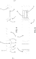
Figure 13 shows the fastener ofFigure 12 seen from the right-hand side; -
Figure 14 is a cross-section of the fastener ofFigure 13 according to the line XIV - XIV; -
Figure 15 is a cross-section of the fastener ofFigure 12 according to the line XV - XV; -
Figure 16 is a top view of the fastener ofFigure 12 ; -
Figure 17 is an enlarged view of the detail XVII ofFigure 14 ; -
Figure 18 is an enlarged view of the detail XVIII ofFigure 15 ; -
Figure 19 is an enlarged view of the detail XIX ofFigure 15 ; -
Figure 20 shows the fastener ofFigure 12 in an unhooking configuration; -
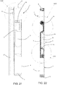
Figure 21 is a cross-section of the fastener ofFigure 20 according to the cross-section plane XIV - XIV ofFigure 13 ; -
Figure 22 is a cross-section of the fastener ofFigure 20 according to the plane XXII - XXII; -
Figure 23 is an enlarged view of the detail XXIII ofFigure 21 ; -
Figure 24 is an enlarged view of the detail XXIV ofFigure 22 ; and -
Figure 25 is an enlarged view of the detail XXIV ofFigure 22 ; -
Figure 26 is an axonometric three-quarter front view of a fastener made according to a second embodiment of this invention; -
Figure 27 is an exploded view of the fastener ofFigure 26 ; -
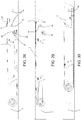
Figure 28 is a transparent side view of the fastener ofFigure 26 with its insert in a first position which in use corresponds to locking of the side board and with a related selective locking unit in a locking position; -
Figure 29 shows the fastener ofFigure 28 with the insert in the first position and the selective locking unit in a releasing position; and -
Figure 30 shows the fastener ofFigure 28 with the insert in a second position which in use corresponds to releasing of the side board. - With reference to the accompanying drawings, the
numeral 1 denotes in its entirety a manually operated fastener for the side boards of industrial vehicle bodies according to this invention. - Similarly to prior art fasteners, even the fastener according to this invention comprises first a
hollow containment casing 2 in which aninsert 3 is slidably inserted. - Depending on requirements, in use the
containment casing 2 may be fixed either to a side board of an industrial vehicle body or to another part of the vehicle body to which the side board must be hooked. It should be noticed that similarly to what is indicated relative to the prior art, in the case of this invention too, the other part of the vehicle body to which the side board must be hooked may be either a part rigidly fixed to the frame (such as an upright) or another side board. - The
containment casing 2 also has a main axis of extension which, at least when the side board is closed, is positioned perpendicularly to the loading platform of the vehicle body. - In the preferred embodiments, illustrated in the accompanying drawings, the
containment casing 2 comprises a tubular body 4 (advantageously metal) with a substantially rectangular cross-section, having two larger sides and two smaller sides, closed byplugs 5 at the ends. - The
containment casing 2 also comprises amain opening 6, made in afirst face 7 of it parallel to the main axis of extension which in use is facing outwards from the vehicle body, and asecondary opening 8 made in asecond face 9 of it positioned transversally relative to thefirst face 7. In the preferred embodiments themain opening 6 and thesecondary opening 8 are made in thetubular body 4, respectively at one of the larger sides and one of the smaller sides of the rectangular cross-section. - As already indicated, the
insert 3 is slidably inserted in thecontainment casing 2, and is movable along the main axis of extension between a first position (Figures 14 and 15 ) and a second position (Figures 21 to 22 ). As is explained in more detail below, the first position in use corresponds to side board locking, whilst the second position in use corresponds to side board releasing. - At least a first connecting
element 10 is fixed to theinsert 3 and is positioned at thesecondary opening 8 both when theinsert 3 is in the first position and when it is in the second position. That first connectingelement 10 in use is hookable to a second connectingelement 11 which is respectively fixed to the other part of the vehicle body or to the side board. In the preferred embodiments the two connectingelements element 10 is constituted of the pin and is screwed into atubular seat 12 made in theinsert 3 and extending perpendicular to the main axis of extension. - According to a first inventive aspect of this invention, the
insert 3 comprises amovement recess 13 accessible through themain opening 6 both when theinsert 3 is in the first position and when theinsert 3 is in the second position, and by means of which theinsert 3 can be moved between the first position and the second position. As shown for example inFigure 4 , along the main axis of extension theinsert 3 is delimited by afirst wall 14 and asecond wall 15 which are positioned transversally to the main axis of extension and on which the user can act to cause shifting of theinsert 3 between the first position and the second position. In particular, the user pushes on thefirst wall 14 to cause shifting of theinsert 3 towards the first position and on thesecond wall 15 to cause shifting of theinsert 3 towards the second position. In the embodiments illustrated, thefirst wall 14 and thesecond wall 15 are stepped, concave with the concavities facing each other, and converge with one another towards the inside of therecess 13. Whilst in the preferred embodiments theentire recess 13 is always completely facing themain opening 6 irrespective of whether or not theinsert 3 is in the first position, in the second position or in an intermediate position, in other embodiments it is sufficient that when theinsert 3 is in the first position thesecond wall 15 is accessible and that when theinsert 3 is in the second position thefirst wall 14 is accessible. - According to a second inventive aspect of this invention, the
fastener 1 also comprises aselective locking unit 16 which is associated with theinsert 3 and is switchable, at least when theinsert 3 is in the first position, between a locking position in which it prevents theinsert 3 from sliding towards the second position, and a releasing position in which allowsinsert 3 sliding towards the second position. The function of theselective locking unit 16 is to prevent the side board from being accidentally unhooked. Advantageously, theselective locking unit 16 comprises anengagement element 17 connected respectively either to theinsert 3 or to thecontainment casing 2 and engageable respectively either with thecontainment casing 2 or with theinsert 3 when theinsert 3 is in the first position and theselective locking unit 16 is in the locking position. Thefastener 1 also comprises elastic means 18 which act on theengagement element 17 for pushing it towards the locking position. - However, in the preferred embodiments the
engagement element 17 is connected to theinsert 3 and, when theinsert 3 is in the first position and theselective locking unit 16 is in the locking position, theengagement element 17 is accessible through themain opening 6 and is engaged with anedge 19 of themain opening 6 extending transversally to the main axis of extension. Advantageously, thanks to the fact that in the locking position theengagement element 17 is at themain opening 6, theengagement element 17 can be switched from the locking position to the releasing position by a pressure applied directly on it. In the preferred embodiments, theengagement element 17 is constituted of a projecting tooth fixed to the insert 3 (Figures 1 and3 ). - In particular, in the first embodiment illustrated in
Figures 1 to 25 , theinsert 3 comprises a lockingportion 20 which is deformable or shiftable relative to the rest of theinsert 3, and to which theengagement element 17 is connected. The switching of theengagement element 17 from the locking position to the releasing position occurs by deformation or shifting of the lockingportion 20 relative to the rest of theinsert 3. - However, in the first embodiment illustrated, the locking
portion 20 is elastically deformable relative to the rest of theinsert 3 and is part of, or constitutes, theelastic means 18. In fact, depending on requirements, the elastic means 18 may be constituted exclusively of the elastic deformability of the lockingportion 20 or may also comprise one or more springs which act on the lockingportion 20. For example, in the first embodiment illustrated two springs could be inserted in the twofirst housings 21 made on the side of the lockingportion 20 opposite that where theengagement element 17 is made. - As shown in particular in
Figures 1 ,3 and4 , in that embodiment theinsert 3 comprises twocantilever portions portion 20 and has a reduced thickness at thezone 23 where it is connected to the rest of theinsert 3 for increasing its deformability (Figure 4 ). The other 22 can act as a fixed contact element for any springs (in fact, the above-mentionedfirst housings 21 are also present in that cantilever portion) or as a guide for sliding of theinsert 3 inside thecontainment casing 2. - Thanks to the special shape of the
fastener 1 according to this invention, in all of the positions of theinsert 3 the overall dimensions of thefastener 1 always substantially correspond only to those of the containment casing 2 (seeFigures 15 and22 ). In other words, whatever position theinsert 3 is in, there are no parts of thefastener 1 projecting from themain opening 6 except for theengagement element 17. The only part which, if present, has to project relative to thecontainment casing 2 is in fact the pin with the enlarged head. - Moreover, in the first embodiment illustrated, the
insert 3 and theselective locking unit 16 are made in one piece. - Furthermore, in the first embodiment illustrated a finishing
element 24 may also be applied to theinsert 3. The finishing element is only shown inFigures 10 and 11 , being constituted of a customisable plate (the accompanying drawings show, by way of example only, the text "OPEN" to indicate that when that text is visible thefastener 1 is released, and similarly the text "CLOSE" directly on theinsert 3 which, when visible, indicates that thefastener 1 is in the locking configuration). On the back of the finishing element there are three irreversible hookingheads 25 insertable in correspondingholes 26 made in theinsert 3. The finishingelement 24 also has a safety function. In fact, the finishingelement 24 is positioned on theinsert 3 in such a way that it is at least partly facing themain opening 6 when the insert is not in the first position and in contrast is completely not facing themain opening 6 and is therefore hidden from view when theinsert 3 is in the first position. In fact, in this way, by making the finishingelement 24 in a different colour to theinsert 3, it is possible to visually show the operator when the fastener is not completely closed. In fact, if the operator can see the colour of the finishingelement 24, he knows that the fastener is still not correctly closed. However, the same result may also be achieved in other ways, such as that shown by way of example inFigure 26 and described in detail below. -
Figures 26 to 30 show a second embodiment of this invention which differs from the first exclusively as regards the structure of theinsert 3 and of theelastic means 18. Consequently, for greater clarity, inFigures 26 to 30 many parts corresponding to those of the preceding figures are not shown. - Again in the second embodiment, the
engagement element 17 is connected to theinsert 3. But in this case, the elastic means 18 are positioned between theinsert 3 and thecontainment casing 2 for pushing theengagement element 17 towards the locking position at least when theinsert 3 is in the first position. That is in particular advantageously achieved thanks to the fact that the elastic means 18 act between theinsert 3 and aninner surface 30 of the containment casing opposite to the wall in which themain opening 6 is made. - Moreover, in the second embodiment illustrated, the elastic means 18 comprise one or more
first springs 31, advantageously helical springs, associated with theinsert 3 and, for eachfirst spring 31, at least one element forcontact 32 interposed between the relatedfirst spring 31 and the above-mentionedinner surface 30 of thecontainment casing 2. Each element forcontact 32 is positioned in such a way that it slides on theinner surface 30 of thecontainment casing 2 during the shifting movements of theinsert 3 between the first position and the second position. Preferably each element forcontact 32 is constituted of a metal sphere or half-sphere. - Also, in the second embodiment illustrated, the
insert 3 pivots about an axis of rotation passing through the first connectingelement 10 and the secondary opening 8 (the axis of rotation is advantageously defined by the cooperation between the pin which constitutes the first connectingelement 10 and the slot which constitutes the secondary opening 8). The switching of theengagement element 17 between the locking position (Figure 28 ) and the releasing position (Figure 29 ) therefore occurs by means of a rotation of theinsert 3 about said axis of rotation. In particular, when going from the locking position to the releasing position the rotation occurs by overcoming the opposition of the elastic means 18, whilst when going in the opposite direction it is driven by theelastic means 18. - Moreover, only in
Figure 26 , on theinsert 3 there is a text 34 ("SAFE") positioned in such a way that it is completely visible only when theinsert 3 is in the first position, therefore indicating that the side board is correctly locked. - To guarantee correct positioning of the
insert 3 in the first positon and in the second position, in the case of the second embodiment illustrated, theinsert 3 is equipped with selectiveengaging means 35 couplable to suitablesecond housings 36 made in thecontainment casing 2 when theinsert 3 is respectively in the first position (with theselective locking unit 17 in the locking position) and in the second position. In particular, the selecting engagingmeans 35 comprise a secondhelical spring 37 positioned in such a way that it passes through theinsert 3 and is perpendicular to its line of movement. At its ends, said spring pushes twospheres 38 against theinner surface 30 of thecontainment casing 2. In the above-mentioned positions, thespheres 38 are designed to be partly inserted in holes made in thecontainment casing 2 which constitute thesecond housings 36. Obviously, similar selectiveengaging means 35 may also be provided in the first embodiment. - Finally, it should be noticed that nothing prevents connection to the
insert 3 of further elastic elements designed to push it towards one of its positions, as well as the provision of devices similar to theselective locking unit 16 also to hold theinsert 3 in the second position. - This invention may relate both to
fasteners 1 which comprise exclusively thecontainment casing 2 and the various parts mounted in it described above, and tofasteners 1 which also comprise a supportingelement 27 which is elongate and on which the second connectingelement 11 is mounted, as illustrated inFigures 12 to 25 . - In this latter case, the
containment casing 2 and the supportingelement 27 are intended to be fixed, one to the openable side board whose opening andclosing 1 is to be controlled, and the other to a different part of the vehicle body. However, in the case of the embodiments illustrated, both are intended to be mounted on openable side boards which can therefore be hooked to one another. For that purpose, both thecontainment casing 2 and the supportingelement 27 comprise projectingflanges 28 between which it is possible to insert the side boards in such a way that thecontainment casing 2 and the supportingelement 27 constitute an end element of the related side board. - However, in general, the supporting
element 27 and thecontainment casing 2 are positionable side by side and in contact, in such a way that the first connectingelement 10 can be moved, by shifting theinsert 3, between an engaging position in which it is connected to the second connecting element 11 (when theinsert 3 is in the first position -Figure 14 ) and a position for disengaging from the second connecting element 11 (when theinsert 3 is in the second position -Figure 21 ). - When the first connecting
element 10 is constituted of the pin with an enlarged head or of another projecting element, the supportingelement 27 advantageously comprises awindow 29 with which the pin is aligned when theinsert 3 is in the second position (Figure 20 ) and which allows the passage of the pin when the side board is opened and closed. - Finally, obviously, this invention also relates to an industrial vehicle body comprising at least one openable side board, movable between a
closed position 1 and an open position, and which is equipped with thefastener 1 described above. - In general, the side board is provided with an end element at a smaller side of it, and there is a contact element fixed to a part (fixed or movable) of the vehicle body other than the side board equipped with the end element. Depending on the embodiments, the
fastener 1 may constitute respectively the end element of the side board and/or the contact element. In other words, the end element and the contact element comprise, one thecontainment casing 2 and everything contained in it, and the other the supportingelement 27 with the second connectingelement 11. - In the
closed position 1 of the side board, the end element is positioned adjacent to the contact element (or, more precisely, is at least positionable adjacent to it if the latter is in turn fixed to a movable side board of the vehicle body). - Operation of the
fastener 1 according to this invention derives immediately from the description of the structure above. - In a situation with the side board closed and locked (
Figures 14 and 15 and 28), theinsert 3 is in its first position and the first connectingelement 10 is hooked to the second connecting element 11 (in the accompanying drawings the enlarged head is hooked to the pocket). To prevent the side board from accidentally opening, theselective locking unit 16 is in the locking position. Therefore, the tooth is inserted in themain opening 6 and is hooked to theedge 19 of it. In the first embodiment illustrated, that also means that the lockingportion 20 is not deformed. - When an operator wants to open the side board, he acts on the
selective locking unit 16 to move it to the releasing position and then theinsert 3 is shifted to the second position, disengaging the first connectingelement 10 from the second connectingelement 11. In particular, in the first embodiment illustrated, the tooth is pressed towards the inside of thecontainment casing 2, deforming the lockingportion 20, until it is uncoupled from theedge 19 of themain opening 6, then theinsert 3 is pushed towards the second position. At that point, the tooth slides as it rests on the inner part of thecontainment casing 2 as shown inFigure 25 . In contrast, in the second embodiment illustrated, the tooth is pressed towards the inside of thecontainment casing 2, disengaging the spheres from the 38second housings 36 and making theinsert 3 rotate about the axis of rotation, overcoming the resistance of the elastic means 18, until the tooth is uncoupled from theedge 19 of themain opening 6. Then theinsert 3 is pushed towards the second position. At that point, the tooth slides as it rests on the inner part of thecontainment casing 2 as shown inFigure 30 . When theinsert 3 reaches the second position (and thespheres 38 are coupled to the correspondent second housings 36), the side board is free and can be opened. - In contrast, when an operator wants to lock the side board, after again positioning it so that it is drawn near to the contact element, it is sufficient to make the
insert 3 slide towards the first position until the selectinglocking unit 16 is free to return to the locking position (in the cases illustrated until the tooth is free to go back into themain opening 6, driven by the elastic means 18). - In fact, it should be noticed that although in the embodiments illustrated
fastener 1 releasing and locking are carried out respectively by moving theinsert 3 downwards and upwards, in other embodiments there may even be an opposite movement (in that case maintenance of the hooking between the first connectingelement 10 and the second connectingelement 11 is also favoured by gravity). - This invention brings important advantages.
- First, thanks to this invention it was possible to provide a manually operated fastener for the side boards of industrial vehicle bodies which is completely free of elements which may be a danger for operators, whatever configuration the fastener is in.
- Second, the fastener according to this invention is significantly simpler and less expensive than the prior art fasteners.
- Finally, it should be noticed that this invention is relatively easy to produce and that even the cost linked to implementing the invention is not very high. The invention described above may be modified and adapted in several ways without thereby departing from its scope as defined by the appended claims. All details of the invention may be substituted with other technically equivalent elements and the materials used, as well as the shapes and dimensions of the various components, may vary according to requirements.
Claims (15)
- A manually operated fastener for the side boards of industrial vehicle bodies, comprising
a hollow containment casing (2) in use fixable to a side board of an industrial vehicle body or to another part of the body, the containment casing (2) having a main axis of extension and comprising a main opening (6) made in a first face (7) of it parallel to the main axis of extension which in use is facing outwards from the body and a secondary opening (8) made in a second face (9) of it positioned transversally relative to the first face (7);
an insert (3) slidably inserted in the containment casing (2), movable along the main axis of extension between a first position and a second position and comprising a movement recess (13) accessible through the main opening (6) both when the insert (3) is in the first position and when the insert (3) is in the second position, and by means of which the insert (3) can be moved between the first position and the second position;
at least a first connecting element (10) fixed to the insert (3) and positioned at the secondary opening (8) both when the insert (3) is in the first position and when it is in the second position, and in use hookable to a second connecting element (11) respectively fixed to the other part of the body or to the side board; and
a selective locking unit (16) switchable, at least when the insert (3) is in the first position, between a locking position in which it prevents the insert (3) from sliding towards the second position, and a releasing position in which it allows insert (3) sliding towards the second position. - The fastener according to claim 1, characterised in that the selective locking unit (16) comprises an engagement element (17) connected respectively to the insert (3) or to the containment casing (2) and engageable respectively with the containment casing (2) or with the insert (3) when the insert (3) is in the first position and the selective locking unit (16) is in the locking position, and in that the fastener (1) also comprises elastic means (18) which act on the engagement element (17) for pushing it towards the locking position.
- The fastener according to claim 2, characterised in that the engagement element (17) is connected to the insert (3) and in that, when the insert (3) is in the first position and the selective locking unit (16) is in the locking position, the engagement element (17) is accessible through the main opening (6) and can engage with an edge (19) of the main opening (6) extending transversally to the main axis of extension.
- The fastener according to claim 2 or 3, characterised in that the engagement element (17) is connected to the insert (3) and in that the elastic means (18) are positioned between the insert (3) and the containment casing (2) for pushing the engagement element (17) towards the locking position at least when the insert (3) is in the first position.
- The fastener according to claim 4, characterised in that the elastic means (18) comprise one or more first springs (31) associated with the insert (3) and, for each first spring (31), at least one element for contact (32) interposed between the related first spring (31) and an inner surface (30) of the containment casing (2), each element for contact (32) sliding on the inner surface (30) of the containment casing (2) during the shifting of the insert (3) between the first position and the second position.
- The fastener according to claim 4 or 5, characterised in that the insert pivots about an axis of rotation passing through the first connecting element (10) and through the secondary opening (8), the switching of the engagement element between the locking position and the releasing position occurring by means of a rotation of the insert (3) about said axis of rotation.
- The fastener according to claim 2 or 3, characterised in that the insert (3) comprises a locking portion (20) which is deformable or shiftable relative to the rest of the insert (3), and to which the engagement element (17) is connected.
- The fastener according to claim 7, characterised in that the insert (3) comprises two cantilever portions (20), (22) extending mainly parallel to the main axis of extension, facing one another and spaced from each other, one of the cantilever portions (20), (22) constituting the locking portion (20).
- The fastener according to claim 7 or 8, characterised in that the engagement element (17) is a projecting tooth fixed to the locking portion (20).
- The fastener according to any one of claims 7 to 9, characterised in that the locking portion (20) is elastically deformable relative to the rest of the insert (3) and is part of the elastic means (18).
- The fastener according to any one of the preceding claims, characterised in that in all of the positions of the insert (3), the overall dimensions of the fastener substantially correspond to those of the containment casing (2).
- The fastener according to any one of the preceding claims, characterised in that the insert (3) and the selective locking unit (16) are made in one piece.
- The fastener according to any one of the preceding claims, characterised in that it also comprises a finishing element (24) applied to the insert (3), having a different colour to that of the insert (3) and positioned on the insert (3) in such a way that it is at least partly facing the main opening (6) when the insert is not in the first position and in contrast is completely not facing the main opening (6) and is hidden from view when the insert (3) is in the first position.
- The fastener according to any one of the preceding claims, characterised in that it also comprises an elongate supporting element (27) on which the second connecting element (11) is mounted, the supporting element (27) and the containment casing (2) being positionable side by side in such a way that the first connecting element (10) and the second connecting element (11) are connected to one another when the insert (3) is in the first position and disengaged from each other when the insert (3) is in the second position.
- An industrial vehicle body comprising:at least one openable side board, movable between a closed position and an open position, and equipped with an end element at a smaller side of it; anda contact element fixed to a part of the body which is not the side board;in the side board closed position the end element being positioned or positionable adjacent to the contact element;characterised in that it comprises a fastener (1) according to any one of the preceding claims which constitutes respectively the end element of the side board and/or the contact element, in that respectively the contact element or the end element comprise said second connecting element (11), and in that, when the side board is in the closed position and the end element is adjacent to the contact element, the first connecting element (10) is constrained to the second connecting element (11) for preventing movement of the side board when the insert (3) is in the first position and is disengaged from the second connecting element (11) when the insert (3) is in the second position, for allowing shifting of the side board towards the open position.
Applications Claiming Priority (1)
| Application Number | Priority Date | Filing Date | Title |
|---|---|---|---|
| ITVR20140020 | 2014-01-28 |
Publications (2)
| Publication Number | Publication Date |
|---|---|
| EP2933170A1 EP2933170A1 (en) | 2015-10-21 |
| EP2933170B1 true EP2933170B1 (en) | 2018-08-08 |
Family
ID=50349809
Family Applications (1)
| Application Number | Title | Priority Date | Filing Date |
|---|---|---|---|
| EP15152384.2A Not-in-force EP2933170B1 (en) | 2014-01-28 | 2015-01-23 | Manually operated fastener for the side boards of industrial vehicle bodies |
Country Status (1)
| Country | Link |
|---|---|
| EP (1) | EP2933170B1 (en) |
Family Cites Families (3)
| Publication number | Priority date | Publication date | Assignee | Title |
|---|---|---|---|---|
| US6021603A (en) * | 1998-04-07 | 2000-02-08 | Ashland Products, Inc. | Tilt-latch with bolt stop |
| US20020000736A1 (en) * | 1999-06-21 | 2002-01-03 | Tom Musso | Horizontal positioning of dump truck tailgate |
| ITVR20110174A1 (en) * | 2011-09-06 | 2013-03-07 | Gianfranco Natali | HOOKING BODY FOR BODYWORK OF INDUSTRIAL VEHICLES |
-
2015
- 2015-01-23 EP EP15152384.2A patent/EP2933170B1/en not_active Not-in-force
Non-Patent Citations (1)
| Title |
|---|
| None * |
Also Published As
| Publication number | Publication date |
|---|---|
| EP2933170A1 (en) | 2015-10-21 |
Similar Documents
| Publication | Publication Date | Title |
|---|---|---|
| EP3745915B1 (en) | Universal drawer slide | |
| US7849867B2 (en) | Locking device for a tent | |
| US7797838B2 (en) | Retractable blade knife with opening assisted mechanism | |
| TWI228396B (en) | Shield fixing structure of safety helmet | |
| CN102575486B (en) | Flush handle device for a door of a vehicle | |
| EP1598509B1 (en) | Closing device for furniture | |
| KR101673338B1 (en) | Locking device for vehicle sliding door | |
| US20160366971A1 (en) | Protective helmet having a cover plate knock out assembly | |
| EP2463465A2 (en) | Opening and closing device of glovebox for automobile and glovebox assembly having the same | |
| US11337332B1 (en) | Latch with auto-close | |
| US5253917A (en) | Apparatus for fastening a removable roof section of a passenger car | |
| EP3587188B1 (en) | Roof box with locking system | |
| EP2933170A1 (en) | Manually operated fastener for the side boards of industrial vehicle bodies | |
| EP2592210B1 (en) | Locking assembly for windows or doors | |
| JP5448855B2 (en) | Vehicle loading flap | |
| JP6375090B2 (en) | Locking and unlocking mechanism of the hinged door | |
| JP6026448B2 (en) | Double-acting opening / closing door with interlocking opening / closing device and door interlocking opening / closing device | |
| CN108835958B (en) | Gun stock device and gun cabinet | |
| EP1944223B1 (en) | Vehicle bonnet | |
| EP2623695B1 (en) | Device for locking the door of vehicles, such as vans, trucks, road trains, trailers and the like | |
| JP5609733B2 (en) | False lock prevention device and window lock device provided with the same | |
| JP4981591B2 (en) | Slide rail | |
| US20240091965A1 (en) | Knife | |
| US12629851B2 (en) | Knife | |
| JP2008190237A (en) | Opening / closing end locking device |
Legal Events
| Date | Code | Title | Description |
|---|---|---|---|
| PUAI | Public reference made under article 153(3) epc to a published international application that has entered the european phase |
Free format text: ORIGINAL CODE: 0009012 |
|
| AK | Designated contracting states |
Kind code of ref document: A1 Designated state(s): AL AT BE BG CH CY CZ DE DK EE ES FI FR GB GR HR HU IE IS IT LI LT LU LV MC MK MT NL NO PL PT RO RS SE SI SK SM TR |
|
| AX | Request for extension of the european patent |
Extension state: BA ME |
|
| 17P | Request for examination filed |
Effective date: 20160415 |
|
| RBV | Designated contracting states (corrected) |
Designated state(s): AL AT BE BG CH CY CZ DE DK EE ES FI FR GB GR HR HU IE IS IT LI LT LU LV MC MK MT NL NO PL PT RO RS SE SI SK SM TR |
|
| RIN1 | Information on inventor provided before grant (corrected) |
Inventor name: MAYR, THOMAS |
|
| GRAP | Despatch of communication of intention to grant a patent |
Free format text: ORIGINAL CODE: EPIDOSNIGR1 |
|
| STAA | Information on the status of an ep patent application or granted ep patent |
Free format text: STATUS: GRANT OF PATENT IS INTENDED |
|
| INTG | Intention to grant announced |
Effective date: 20180305 |
|
| GRAS | Grant fee paid |
Free format text: ORIGINAL CODE: EPIDOSNIGR3 |
|
| GRAA | (expected) grant |
Free format text: ORIGINAL CODE: 0009210 |
|
| STAA | Information on the status of an ep patent application or granted ep patent |
Free format text: STATUS: THE PATENT HAS BEEN GRANTED |
|
| RAP1 | Party data changed (applicant data changed or rights of an application transferred) |
Owner name: QUINARIO SA |
|
| AK | Designated contracting states |
Kind code of ref document: B1 Designated state(s): AL AT BE BG CH CY CZ DE DK EE ES FI FR GB GR HR HU IE IS IT LI LT LU LV MC MK MT NL NO PL PT RO RS SE SI SK SM TR |
|
| REG | Reference to a national code |
Ref country code: GB Ref legal event code: FG4D |
|
| REG | Reference to a national code |
Ref country code: CH Ref legal event code: EP Ref country code: AT Ref legal event code: REF Ref document number: 1026651 Country of ref document: AT Kind code of ref document: T Effective date: 20180815 |
|
| REG | Reference to a national code |
Ref country code: IE Ref legal event code: FG4D |
|
| REG | Reference to a national code |
Ref country code: DE Ref legal event code: R096 Ref document number: 602015014484 Country of ref document: DE |
|
| REG | Reference to a national code |
Ref country code: NL Ref legal event code: MP Effective date: 20180808 |
|
| REG | Reference to a national code |
Ref country code: LT Ref legal event code: MG4D |
|
| REG | Reference to a national code |
Ref country code: AT Ref legal event code: MK05 Ref document number: 1026651 Country of ref document: AT Kind code of ref document: T Effective date: 20180808 |
|
| PG25 | Lapsed in a contracting state [announced via postgrant information from national office to epo] |
Ref country code: LT Free format text: LAPSE BECAUSE OF FAILURE TO SUBMIT A TRANSLATION OF THE DESCRIPTION OR TO PAY THE FEE WITHIN THE PRESCRIBED TIME-LIMIT Effective date: 20180808 Ref country code: PL Free format text: LAPSE BECAUSE OF FAILURE TO SUBMIT A TRANSLATION OF THE DESCRIPTION OR TO PAY THE FEE WITHIN THE PRESCRIBED TIME-LIMIT Effective date: 20180808 Ref country code: RS Free format text: LAPSE BECAUSE OF FAILURE TO SUBMIT A TRANSLATION OF THE DESCRIPTION OR TO PAY THE FEE WITHIN THE PRESCRIBED TIME-LIMIT Effective date: 20180808 Ref country code: IS Free format text: LAPSE BECAUSE OF FAILURE TO SUBMIT A TRANSLATION OF THE DESCRIPTION OR TO PAY THE FEE WITHIN THE PRESCRIBED TIME-LIMIT Effective date: 20181208 Ref country code: AT Free format text: LAPSE BECAUSE OF FAILURE TO SUBMIT A TRANSLATION OF THE DESCRIPTION OR TO PAY THE FEE WITHIN THE PRESCRIBED TIME-LIMIT Effective date: 20180808 Ref country code: GR Free format text: LAPSE BECAUSE OF FAILURE TO SUBMIT A TRANSLATION OF THE DESCRIPTION OR TO PAY THE FEE WITHIN THE PRESCRIBED TIME-LIMIT Effective date: 20181109 Ref country code: NO Free format text: LAPSE BECAUSE OF FAILURE TO SUBMIT A TRANSLATION OF THE DESCRIPTION OR TO PAY THE FEE WITHIN THE PRESCRIBED TIME-LIMIT Effective date: 20181108 Ref country code: SE Free format text: LAPSE BECAUSE OF FAILURE TO SUBMIT A TRANSLATION OF THE DESCRIPTION OR TO PAY THE FEE WITHIN THE PRESCRIBED TIME-LIMIT Effective date: 20180808 Ref country code: FI Free format text: LAPSE BECAUSE OF FAILURE TO SUBMIT A TRANSLATION OF THE DESCRIPTION OR TO PAY THE FEE WITHIN THE PRESCRIBED TIME-LIMIT Effective date: 20180808 Ref country code: BG Free format text: LAPSE BECAUSE OF FAILURE TO SUBMIT A TRANSLATION OF THE DESCRIPTION OR TO PAY THE FEE WITHIN THE PRESCRIBED TIME-LIMIT Effective date: 20181108 Ref country code: NL Free format text: LAPSE BECAUSE OF FAILURE TO SUBMIT A TRANSLATION OF THE DESCRIPTION OR TO PAY THE FEE WITHIN THE PRESCRIBED TIME-LIMIT Effective date: 20180808 |
|
| PG25 | Lapsed in a contracting state [announced via postgrant information from national office to epo] |
Ref country code: HR Free format text: LAPSE BECAUSE OF FAILURE TO SUBMIT A TRANSLATION OF THE DESCRIPTION OR TO PAY THE FEE WITHIN THE PRESCRIBED TIME-LIMIT Effective date: 20180808 Ref country code: AL Free format text: LAPSE BECAUSE OF FAILURE TO SUBMIT A TRANSLATION OF THE DESCRIPTION OR TO PAY THE FEE WITHIN THE PRESCRIBED TIME-LIMIT Effective date: 20180808 Ref country code: LV Free format text: LAPSE BECAUSE OF FAILURE TO SUBMIT A TRANSLATION OF THE DESCRIPTION OR TO PAY THE FEE WITHIN THE PRESCRIBED TIME-LIMIT Effective date: 20180808 |
|
| PG25 | Lapsed in a contracting state [announced via postgrant information from national office to epo] |
Ref country code: RO Free format text: LAPSE BECAUSE OF FAILURE TO SUBMIT A TRANSLATION OF THE DESCRIPTION OR TO PAY THE FEE WITHIN THE PRESCRIBED TIME-LIMIT Effective date: 20180808 Ref country code: CZ Free format text: LAPSE BECAUSE OF FAILURE TO SUBMIT A TRANSLATION OF THE DESCRIPTION OR TO PAY THE FEE WITHIN THE PRESCRIBED TIME-LIMIT Effective date: 20180808 Ref country code: ES Free format text: LAPSE BECAUSE OF FAILURE TO SUBMIT A TRANSLATION OF THE DESCRIPTION OR TO PAY THE FEE WITHIN THE PRESCRIBED TIME-LIMIT Effective date: 20180808 Ref country code: EE Free format text: LAPSE BECAUSE OF FAILURE TO SUBMIT A TRANSLATION OF THE DESCRIPTION OR TO PAY THE FEE WITHIN THE PRESCRIBED TIME-LIMIT Effective date: 20180808 |
|
| REG | Reference to a national code |
Ref country code: DE Ref legal event code: R097 Ref document number: 602015014484 Country of ref document: DE |
|
| PG25 | Lapsed in a contracting state [announced via postgrant information from national office to epo] |
Ref country code: DK Free format text: LAPSE BECAUSE OF FAILURE TO SUBMIT A TRANSLATION OF THE DESCRIPTION OR TO PAY THE FEE WITHIN THE PRESCRIBED TIME-LIMIT Effective date: 20180808 Ref country code: SM Free format text: LAPSE BECAUSE OF FAILURE TO SUBMIT A TRANSLATION OF THE DESCRIPTION OR TO PAY THE FEE WITHIN THE PRESCRIBED TIME-LIMIT Effective date: 20180808 Ref country code: SK Free format text: LAPSE BECAUSE OF FAILURE TO SUBMIT A TRANSLATION OF THE DESCRIPTION OR TO PAY THE FEE WITHIN THE PRESCRIBED TIME-LIMIT Effective date: 20180808 |
|
| PLBE | No opposition filed within time limit |
Free format text: ORIGINAL CODE: 0009261 |
|
| STAA | Information on the status of an ep patent application or granted ep patent |
Free format text: STATUS: NO OPPOSITION FILED WITHIN TIME LIMIT |
|
| 26N | No opposition filed |
Effective date: 20190509 |
|
| PG25 | Lapsed in a contracting state [announced via postgrant information from national office to epo] |
Ref country code: SI Free format text: LAPSE BECAUSE OF FAILURE TO SUBMIT A TRANSLATION OF THE DESCRIPTION OR TO PAY THE FEE WITHIN THE PRESCRIBED TIME-LIMIT Effective date: 20180808 Ref country code: MC Free format text: LAPSE BECAUSE OF FAILURE TO SUBMIT A TRANSLATION OF THE DESCRIPTION OR TO PAY THE FEE WITHIN THE PRESCRIBED TIME-LIMIT Effective date: 20180808 |
|
| PG25 | Lapsed in a contracting state [announced via postgrant information from national office to epo] |
Ref country code: LU Free format text: LAPSE BECAUSE OF NON-PAYMENT OF DUE FEES Effective date: 20190123 |
|
| REG | Reference to a national code |
Ref country code: BE Ref legal event code: MM Effective date: 20190131 |
|
| REG | Reference to a national code |
Ref country code: IE Ref legal event code: MM4A |
|
| PG25 | Lapsed in a contracting state [announced via postgrant information from national office to epo] |
Ref country code: BE Free format text: LAPSE BECAUSE OF NON-PAYMENT OF DUE FEES Effective date: 20190131 |
|
| PG25 | Lapsed in a contracting state [announced via postgrant information from national office to epo] |
Ref country code: IE Free format text: LAPSE BECAUSE OF NON-PAYMENT OF DUE FEES Effective date: 20190123 |
|
| PG25 | Lapsed in a contracting state [announced via postgrant information from national office to epo] |
Ref country code: TR Free format text: LAPSE BECAUSE OF FAILURE TO SUBMIT A TRANSLATION OF THE DESCRIPTION OR TO PAY THE FEE WITHIN THE PRESCRIBED TIME-LIMIT Effective date: 20180808 |
|
| PG25 | Lapsed in a contracting state [announced via postgrant information from national office to epo] |
Ref country code: PT Free format text: LAPSE BECAUSE OF FAILURE TO SUBMIT A TRANSLATION OF THE DESCRIPTION OR TO PAY THE FEE WITHIN THE PRESCRIBED TIME-LIMIT Effective date: 20181208 Ref country code: MT Free format text: LAPSE BECAUSE OF NON-PAYMENT OF DUE FEES Effective date: 20190123 |
|
| PGFP | Annual fee paid to national office [announced via postgrant information from national office to epo] |
Ref country code: CH Payment date: 20210122 Year of fee payment: 7 Ref country code: FR Payment date: 20210127 Year of fee payment: 7 Ref country code: IT Payment date: 20210121 Year of fee payment: 7 |
|
| PG25 | Lapsed in a contracting state [announced via postgrant information from national office to epo] |
Ref country code: CY Free format text: LAPSE BECAUSE OF FAILURE TO SUBMIT A TRANSLATION OF THE DESCRIPTION OR TO PAY THE FEE WITHIN THE PRESCRIBED TIME-LIMIT Effective date: 20180808 |
|
| PGFP | Annual fee paid to national office [announced via postgrant information from national office to epo] |
Ref country code: GB Payment date: 20210128 Year of fee payment: 7 |
|
| PG25 | Lapsed in a contracting state [announced via postgrant information from national office to epo] |
Ref country code: HU Free format text: LAPSE BECAUSE OF FAILURE TO SUBMIT A TRANSLATION OF THE DESCRIPTION OR TO PAY THE FEE WITHIN THE PRESCRIBED TIME-LIMIT; INVALID AB INITIO Effective date: 20150123 |
|
| PGFP | Annual fee paid to national office [announced via postgrant information from national office to epo] |
Ref country code: DE Payment date: 20210329 Year of fee payment: 7 |
|
| PG25 | Lapsed in a contracting state [announced via postgrant information from national office to epo] |
Ref country code: MK Free format text: LAPSE BECAUSE OF FAILURE TO SUBMIT A TRANSLATION OF THE DESCRIPTION OR TO PAY THE FEE WITHIN THE PRESCRIBED TIME-LIMIT Effective date: 20180808 |
|
| REG | Reference to a national code |
Ref country code: DE Ref legal event code: R119 Ref document number: 602015014484 Country of ref document: DE |
|
| REG | Reference to a national code |
Ref country code: CH Ref legal event code: PL |
|
| GBPC | Gb: european patent ceased through non-payment of renewal fee |
Effective date: 20220123 |
|
| PG25 | Lapsed in a contracting state [announced via postgrant information from national office to epo] |
Ref country code: GB Free format text: LAPSE BECAUSE OF NON-PAYMENT OF DUE FEES Effective date: 20220123 Ref country code: DE Free format text: LAPSE BECAUSE OF NON-PAYMENT OF DUE FEES Effective date: 20220802 |
|
| PG25 | Lapsed in a contracting state [announced via postgrant information from national office to epo] |
Ref country code: FR Free format text: LAPSE BECAUSE OF NON-PAYMENT OF DUE FEES Effective date: 20220131 |
|
| PG25 | Lapsed in a contracting state [announced via postgrant information from national office to epo] |
Ref country code: LI Free format text: LAPSE BECAUSE OF NON-PAYMENT OF DUE FEES Effective date: 20220131 Ref country code: CH Free format text: LAPSE BECAUSE OF NON-PAYMENT OF DUE FEES Effective date: 20220131 |
|
| PG25 | Lapsed in a contracting state [announced via postgrant information from national office to epo] |
Ref country code: IT Free format text: LAPSE BECAUSE OF NON-PAYMENT OF DUE FEES Effective date: 20220123 |