EP2933058A1 - System and methods of removing a multi-layer coating from a substrate - Google Patents
System and methods of removing a multi-layer coating from a substrate Download PDFInfo
- Publication number
- EP2933058A1 EP2933058A1 EP15162441.8A EP15162441A EP2933058A1 EP 2933058 A1 EP2933058 A1 EP 2933058A1 EP 15162441 A EP15162441 A EP 15162441A EP 2933058 A1 EP2933058 A1 EP 2933058A1
- Authority
- EP
- European Patent Office
- Prior art keywords
- coating
- grinding mechanism
- substrate
- removal mode
- operating parameter
- Prior art date
- Legal status (The legal status is an assumption and is not a legal conclusion. Google has not performed a legal analysis and makes no representation as to the accuracy of the status listed.)
- Granted
Links
Images

Classifications
-
- B—PERFORMING OPERATIONS; TRANSPORTING
- B24—GRINDING; POLISHING
- B24B—MACHINES, DEVICES, OR PROCESSES FOR GRINDING OR POLISHING; DRESSING OR CONDITIONING OF ABRADING SURFACES; FEEDING OF GRINDING, POLISHING, OR LAPPING AGENTS
- B24B49/00—Measuring or gauging equipment for controlling the feed movement of the grinding tool or work; Arrangements of indicating or measuring equipment, e.g. for indicating the start of the grinding operation
- B24B49/02—Measuring or gauging equipment for controlling the feed movement of the grinding tool or work; Arrangements of indicating or measuring equipment, e.g. for indicating the start of the grinding operation according to the instantaneous size and required size of the workpiece acted upon, the measuring or gauging being continuous or intermittent
-
- B—PERFORMING OPERATIONS; TRANSPORTING
- B08—CLEANING
- B08B—CLEANING IN GENERAL; PREVENTION OF FOULING IN GENERAL
- B08B1/00—Cleaning by methods involving the use of tools
- B08B1/30—Cleaning by methods involving the use of tools by movement of cleaning members over a surface
- B08B1/32—Cleaning by methods involving the use of tools by movement of cleaning members over a surface using rotary cleaning members
- B08B1/34—Cleaning by methods involving the use of tools by movement of cleaning members over a surface using rotary cleaning members rotating about an axis parallel to the surface
-
- B—PERFORMING OPERATIONS; TRANSPORTING
- B23—MACHINE TOOLS; METAL-WORKING NOT OTHERWISE PROVIDED FOR
- B23P—METAL-WORKING NOT OTHERWISE PROVIDED FOR; COMBINED OPERATIONS; UNIVERSAL MACHINE TOOLS
- B23P6/00—Restoring or reconditioning objects
-
- B—PERFORMING OPERATIONS; TRANSPORTING
- B23—MACHINE TOOLS; METAL-WORKING NOT OTHERWISE PROVIDED FOR
- B23P—METAL-WORKING NOT OTHERWISE PROVIDED FOR; COMBINED OPERATIONS; UNIVERSAL MACHINE TOOLS
- B23P6/00—Restoring or reconditioning objects
- B23P6/002—Repairing turbine components, e.g. moving or stationary blades, rotors
-
- B—PERFORMING OPERATIONS; TRANSPORTING
- B24—GRINDING; POLISHING
- B24B—MACHINES, DEVICES, OR PROCESSES FOR GRINDING OR POLISHING; DRESSING OR CONDITIONING OF ABRADING SURFACES; FEEDING OF GRINDING, POLISHING, OR LAPPING AGENTS
- B24B19/00—Single-purpose machines or devices for particular grinding operations not covered by any other main group
- B24B19/14—Single-purpose machines or devices for particular grinding operations not covered by any other main group for grinding turbine blades, propeller blades or the like
-
- B—PERFORMING OPERATIONS; TRANSPORTING
- B24—GRINDING; POLISHING
- B24B—MACHINES, DEVICES, OR PROCESSES FOR GRINDING OR POLISHING; DRESSING OR CONDITIONING OF ABRADING SURFACES; FEEDING OF GRINDING, POLISHING, OR LAPPING AGENTS
- B24B19/00—Single-purpose machines or devices for particular grinding operations not covered by any other main group
- B24B19/22—Single-purpose machines or devices for particular grinding operations not covered by any other main group characterised by a special design with respect to properties of the material of non-metallic articles to be ground
-
- B—PERFORMING OPERATIONS; TRANSPORTING
- B24—GRINDING; POLISHING
- B24B—MACHINES, DEVICES, OR PROCESSES FOR GRINDING OR POLISHING; DRESSING OR CONDITIONING OF ABRADING SURFACES; FEEDING OF GRINDING, POLISHING, OR LAPPING AGENTS
- B24B27/00—Other grinding machines or devices
- B24B27/033—Other grinding machines or devices for grinding a surface for cleaning purposes, e.g. for descaling or for grinding off flaws in the surface
-
- B—PERFORMING OPERATIONS; TRANSPORTING
- B24—GRINDING; POLISHING
- B24B—MACHINES, DEVICES, OR PROCESSES FOR GRINDING OR POLISHING; DRESSING OR CONDITIONING OF ABRADING SURFACES; FEEDING OF GRINDING, POLISHING, OR LAPPING AGENTS
- B24B49/00—Measuring or gauging equipment for controlling the feed movement of the grinding tool or work; Arrangements of indicating or measuring equipment, e.g. for indicating the start of the grinding operation
-
- B—PERFORMING OPERATIONS; TRANSPORTING
- B24—GRINDING; POLISHING
- B24B—MACHINES, DEVICES, OR PROCESSES FOR GRINDING OR POLISHING; DRESSING OR CONDITIONING OF ABRADING SURFACES; FEEDING OF GRINDING, POLISHING, OR LAPPING AGENTS
- B24B49/00—Measuring or gauging equipment for controlling the feed movement of the grinding tool or work; Arrangements of indicating or measuring equipment, e.g. for indicating the start of the grinding operation
- B24B49/006—Measuring or gauging equipment for controlling the feed movement of the grinding tool or work; Arrangements of indicating or measuring equipment, e.g. for indicating the start of the grinding operation taking regard of the speed
-
- B—PERFORMING OPERATIONS; TRANSPORTING
- B24—GRINDING; POLISHING
- B24B—MACHINES, DEVICES, OR PROCESSES FOR GRINDING OR POLISHING; DRESSING OR CONDITIONING OF ABRADING SURFACES; FEEDING OF GRINDING, POLISHING, OR LAPPING AGENTS
- B24B49/00—Measuring or gauging equipment for controlling the feed movement of the grinding tool or work; Arrangements of indicating or measuring equipment, e.g. for indicating the start of the grinding operation
- B24B49/16—Measuring or gauging equipment for controlling the feed movement of the grinding tool or work; Arrangements of indicating or measuring equipment, e.g. for indicating the start of the grinding operation taking regard of the load
-
- B—PERFORMING OPERATIONS; TRANSPORTING
- B24—GRINDING; POLISHING
- B24B—MACHINES, DEVICES, OR PROCESSES FOR GRINDING OR POLISHING; DRESSING OR CONDITIONING OF ABRADING SURFACES; FEEDING OF GRINDING, POLISHING, OR LAPPING AGENTS
- B24B7/00—Machines or devices designed for grinding plane surfaces on work, including polishing plane glass surfaces; Accessories therefor
- B24B7/20—Machines or devices designed for grinding plane surfaces on work, including polishing plane glass surfaces; Accessories therefor characterised by a special design with respect to properties of the material of non-metallic articles to be ground
-
- F—MECHANICAL ENGINEERING; LIGHTING; HEATING; WEAPONS; BLASTING
- F01—MACHINES OR ENGINES IN GENERAL; ENGINE PLANTS IN GENERAL; STEAM ENGINES
- F01D—NON-POSITIVE DISPLACEMENT MACHINES OR ENGINES, e.g. STEAM TURBINES
- F01D5/00—Blades; Blade-carrying members; Heating, heat-insulating, cooling or antivibration means on the blades or the members
- F01D5/005—Repairing methods or devices
-
- F—MECHANICAL ENGINEERING; LIGHTING; HEATING; WEAPONS; BLASTING
- F01—MACHINES OR ENGINES IN GENERAL; ENGINE PLANTS IN GENERAL; STEAM ENGINES
- F01D—NON-POSITIVE DISPLACEMENT MACHINES OR ENGINES, e.g. STEAM TURBINES
- F01D5/00—Blades; Blade-carrying members; Heating, heat-insulating, cooling or antivibration means on the blades or the members
- F01D5/12—Blades
- F01D5/28—Selecting particular materials; Particular measures relating thereto; Measures against erosion or corrosion
- F01D5/288—Protective coatings for blades
Definitions
- the present disclosure relates generally to turbine components having coatings applied thereon and, more specifically, systems and methods of automated removal of coatings from turbine components.
- TBC thermal barrier coating
- Known TBC systems must have a low thermal conductivity, must strongly adhere to the component, and must remain adherent throughout many heating and cooling cycles.
- TBC systems generally include a metallic bond coating that facilitates adhering a thermally-insulating ceramic coating to the component.
- Thermally-insulating ceramic coatings are generally formed from metal oxides such as zirconia (ZrO 2 ) partially or fully stabilized by yttria (Y 2 O 3 ), magnesia (MgO) or other oxides, and metallic bond coatings are generally formed from oxidation-resistant diffusion coatings such as a diffusion aluminide or platinum aluminide, or an oxidation-resistant alloy such as MCrAlY (where M is iron, cobalt and/or nickel).
- ZrO 2 zirconia
- Y 2 O 3 yttria
- MgO magnesia
- metallic bond coatings are generally formed from oxidation-resistant diffusion coatings such as a diffusion aluminide or platinum aluminide, or an oxidation-resistant alloy such as MCrAlY (where M is iron, cobalt and/or nickel).
- At least some known gas turbine engine components have a predetermined service life. However, the components may be refurbished by removing a remaining TBC system therefrom, and by reapplying a new TBC system to the components.
- Several known processes are generally used for removing remaining TBC systems from turbine components. Exemplary processes include, but are not limited to, mechanical grinding, acid stripping, and water jet blasting.
- it may be difficult to determine a duration in which to apply the removal process while also reducing substrate material removal.
- such known processes generally must be monitored and the components manually inspected to determine whether the removal process should continue.
- a system for use in removing a multi-layer coating from a substrate includes at least one layer of a first coating applied to the substrate and at least one layer of a second coating applied over the first coating.
- the first coating is formed from a first material and the second coating is formed from a second material different from the first material.
- the system includes a grinding mechanism configured to remove the multi-layer coating from the substrate, and a controller coupled in communication with the grinding mechanism.
- the controller is configured to position the grinding mechanism against the multi-layer coating, initiate a first removal mode that directs the grinding mechanism to traverse across the substrate, monitor a variable operating parameter of the grinding mechanism during the first removal mode, and evaluate a value of the variable operating parameter against a predetermined threshold to determine whether the second coating has been removed from the substrate.
- a method of removing a multi-layer coating from a substrate includes at least one layer of a first coating applied to the substrate and at least one layer of a second coating applied over the first coating.
- the first coating is formed from a first material and the second coating is formed from a second material different from the first material.
- the method includes positioning a grinding mechanism against the multi-layer coating, the grinding mechanism configured to remove the multi-layer coating from the substrate, initiating a first removal mode that directs the grinding mechanism to traverse across the substrate, monitoring a variable operating parameter of the grinding mechanism during the first removal mode, and evaluating a value of the variable operating parameter against a predetermined threshold to determine whether the second coating has been removed from the substrate.
- a non-transitory computer-readable medium having computer-executable instructions embodied thereon for use in removing a multi-layer coating from a substrate.
- the multi-layer coating includes at least one layer of a first coating applied to the substrate and at least one layer of a second coating applied over the first coating.
- the first coating is formed from a first material and the second coating is formed from a second material different from the first material.
- the computer-executable instructions When executed by a controller, the computer-executable instructions cause the controller to position a grinding mechanism against the multi-layer coating, initiate a first removal mode that directs the grinding mechanism to traverse across the substrate, monitor a variable operating parameter of the grinding mechanism during the first removal mode, and evaluate a value of the variable operating parameter against a predetermined threshold to determine whether the second coating has been removed from the substrate.
- Embodiments of the present disclosure relate to systems and methods of removing a multi-layer coating from a substrate. More specifically, the systems and methods described herein facilitate detecting when layers of coating material are removed from the substrate by continuously monitoring a variable operating parameter of a grinding mechanism as it removes the multi-layer coating.
- the multi-layer coating is formed from at least one layer of a first coating and at least one layer of a second coating.
- the first and second coatings are formed from different materials such that as the grinding mechanism removes the multi-layer coating, an evaluation of when each layer is being engaged by the grinding mechanism is determined based on a value of the variable operating parameter.
- the technical effect of the systems and methods described herein includes automated coating removal that facilitates increasing the accuracy of coating removal from substrates.
- FIG. 1 is a block diagram of an exemplary coating removal system 100.
- coating removal system 100 includes a grinding mechanism 102 and a controller 104 coupled in communication with grinding mechanism 102.
- Grinding mechanism 102 is operable to mechanically remove a multi-layer coating from a substrate (each not shown in FIG. 1 ).
- the substrate is a gas turbine engine component such as, but not limited to, a bucket, a nozzle, an airfoil, and/or a shroud tile.
- Controller 104 includes a memory 106 (i.e., a non-transitory computer-readable medium) and a processor 108 coupled to memory 106 for executing programmed instructions.
- Processor 108 may include one or more processing units (e.g., in a multi-core configuration) and/or include a cryptographic accelerator (not shown).
- Controller 104 is programmable to perform one or more operations described herein by programming memory 106 and/or processor 108.
- processor 108 may be programmed by encoding an operation as executable instructions and providing the executable instructions in memory 106.
- Processor 108 may include, but is not limited to, a general purpose central processing unit (CPU), a microcontroller, a reduced instruction set computer (RISC) processor, an open media application platform (OMAP), an application specific integrated circuit (ASIC), a programmable logic circuit (PLC), and/or any other circuit or processor capable of executing the functions described herein.
- the methods described herein may be encoded as executable instructions embodied in a computer-readable medium including, without limitation, a storage device and/or a memory device. Such instructions, when executed by processor 108, cause processor 108 to perform at least a portion of the functions described herein.
- the above examples are exemplary only, and thus are not intended to limit in any way the definition and/or meaning of the term processor.
- Memory 106 is one or more devices that enable information such as executable instructions and/or other data to be stored and retrieved.
- Memory 106 may include one or more computer-readable media, such as, without limitation, dynamic random access memory (DRAM), synchronous dynamic random access memory (SDRAM), static random access memory (SRAM), a solid state disk, and/or a hard disk.
- DRAM dynamic random access memory
- SDRAM synchronous dynamic random access memory
- SRAM static random access memory
- Solid state disk and/or a hard disk.
- Memory 106 may be configured to store, without limitation, executable instructions, operating systems, applications, resources, installation scripts and/or any other type of data suitable for use with the methods and systems described herein.
- Non-transitory memory 106 Instructions for operating systems and applications are located in a functional form on non-transitory memory 106 for execution by processor 108 to perform one or more of the processes described herein.
- These instructions in the different implementations may be embodied on different physical or tangible computer-readable media, such as memory 106 or another memory, such as a computer-readable media (not shown), which may include, without limitation, a flash drive and/or thumb drive.
- instructions may be located in a functional form on non-transitory computer-readable media, which may include, without limitation, smart-media (SM) memory, compact flash (CF) memory, secure digital (SD) memory, memory stick (MS) memory, multimedia card (MMC) memory, embedded-multimedia card (e-MMC), and micro-drive memory.
- the computer-readable media may be selectively insertable and/or removable from controller 104 to permit access and/or execution by processor 108. In an alternative implementation, the computer-readable media is not removable.
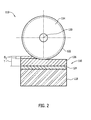
- FIG. 2 is a schematic illustration of coating removal system 100 in a first removal mode 110
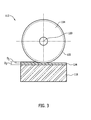
- FIG. 3 is a schematic illustration of coating removal system 100 in a second removal mode 112.
- grinding mechanism 102 includes a grinding wheel 114 positioned against multi-layer coating 116 and operable to mechanically remove multi-layer coating 116 from substrate 118.
- Grinding wheel 114 has a substantially circular shape and rotates about a central axis 120 thereof to grind against and remove multi-layer coating 116 from substrate 118.
- grinding wheel 114 includes an outer surface 122 that contacts multi-layer coating 116.
- Outer surface 122 may be formed from abrasive material such as, but not limited to, vitrified bonded abrasive material (i.e., aluminum oxide and silicon carbide), vitrified bonded cubic boron nitride (CBN), direct-plated super-abrasive material, and resin-bonded abrasive material.
- abrasive material such as, but not limited to, vitrified bonded abrasive material (i.e., aluminum oxide and silicon carbide), vitrified bonded cubic boron nitride (CBN), direct-plated super-abrasive material, and resin-bonded abrasive material.
- grinding mechanism 102 may be any mechanical removal mechanism that enables coating removal system 100 to function as described herein.
- Multi-layer coating 116 includes at least one layer 124 of a first coating applied to substrate 118, and at least one layer 126 of a second coating applied to the first coating.
- the first coating is formed from a first material and the second coating is formed from a second material different from the first material.
- the first coating is formed from a metallic bond coat material, and the second coating is formed from a thermally-insulating ceramic material.
- grinding mechanism 102 and controller 104 are included in a computer numerical control (CNC) machine (not shown).
- CNC computer numerical control
- computer-executable instructions are stored in memory 106 (shown in FIG. 1 ) and, when executed by controller 104, the computer-executable instructions cause controller 104 to perform a variety of functions.
- grinding mechanism 102 is operable in first removal mode 110 to facilitate removing second coating layer 126 from substrate 118.
- controller 104 designates at least one fixed operating parameter and a variable operating parameter for grinding mechanism 102.
- controller 104 monitors the variable operating parameter to determine when second coating layer 126 has been removed from substrate 118.
- the first coating is formed from a first material and the second coating is formed from a second material. Because the first and second coatings are formed from different materials, a value of the variable operating parameter changes when grinding mechanism 102 is engaged with the first coating or the second coating.
- controller 104 designates a grinding wheel speed (i.e., rotations per minute) and a grinding wheel traversal rate across substrate 118 as fixed operating parameters, and power supplied to grinding mechanism 102 as the variable operating parameter. Controller 104 then directs grinding mechanism 102 to operate with the fixed and variable operating parameters. The value of the variable operating parameter is dynamically selected to facilitate maintaining values of the fixed operating parameters. Controller 104 then evaluates the value of the variable operating parameter against a predetermined threshold to determine whether second coating layer 126 has been removed from substrate 118.
- the power required to maintain the wheel speed and/or traversal rate has a first value when grinding mechanism 102 engages second coating layer 126, and has a second value when grinding mechanism 102 engages first coating layer 124.
- the first value is generally greater than the second value.
- controller 104 is able to determine when second coating layer 126 has been removed when the power value is less than the predetermined threshold.
- first removal mode 110 directs grinding mechanism 102 to grind against second coating layer 126 at a first depth D 1 less than a thickness T of second coating layer 126. Specifically, first removal mode 110 directs grinding mechanism 102 to traverse across substrate 118 with a plurality of passes that each grind into multi-layer coating 116 at depth D 1 until second coating layer 126 is removed. Alternatively, each pass may grind into multi-layer coating at any depth less than thickness T of second coating layer 126. The number of passes is selected as a function of the variable operating parameter monitored by controller 104. For example, in the exemplary embodiment, controller 104 substantially continuously monitors the power supplied to grinding mechanism 102 during each pass.
- first removal mode 110 directs grinding mechanism to make another pass. If the power value at points along the traversal path of grinding mechanism 102 during a single pass is both greater than and less than the predetermined threshold, first removal mode 110 directs grinding mechanism 102 to make another pass. If the power value at each point along the traversal path of grinding mechanism 102 during a single pass is less than the predetermined threshold, controller 104 disengages first removal mode 110 and initiates second removal mode 112.
- grinding mechanism 102 is operable in second removal mode 112 to facilitate removing first coating layer 124 from substrate 118.
- Second removal mode 112 is initiated after it is determined that second coating layer 126 (shown in FIG. 2 ) has been removed from substrate 118.
- Second removal mode 112 directs grinding mechanism 102 to grind into first coating layer 124 and at least a portion of substrate 118 until a predetermined second grinding depth D 2 is reached. Because at least a portion of first coating layer 124 diffuses into substrate 118 over time, predetermined second grinding depth D 2 is selected to ensure first coating layer 124 is substantially completely removed from substrate 118.
- second removal mode 112 directs grinding mechanism 102 to traverse across substrate 118 with a plurality of passes.
- the systems and methods described herein facilitate accurate removal of a multi-layer coating from a substrate.
- the multi-layer coating is formed from delineated layers of different coating materials having different physical characteristics such that as a grinding mechanism removes the multi-layer coating, an evaluation of when each layer is being engaged by the grinding mechanism is determined based on a value of a variable operating parameter of the grinding mechanism. More specifically, the value of the variable operating parameter is dynamically selected to facilitate maintaining values of fixed operating parameters of the grinding mechanism. The value of the variable operating parameter is then evaluated against a predetermined threshold to continuously determine progress of the coating removal process.
- the systems and methods described herein facilitate determining an accurate number of machining passes to facilitate reducing substrate material removal, and thus facilitates extending the service life of associated components.
Landscapes
- Engineering & Computer Science (AREA)
- Mechanical Engineering (AREA)
- Constituent Portions Of Griding Lathes, Driving, Sensing And Control (AREA)
- Grinding Of Cylindrical And Plane Surfaces (AREA)
- Mechanical Treatment Of Semiconductor (AREA)
- General Engineering & Computer Science (AREA)
Abstract
Description
- The present disclosure relates generally to turbine components having coatings applied thereon and, more specifically, systems and methods of automated removal of coatings from turbine components.
- Modem gas turbine engines operate in high temperature environments. Components in a gas turbine engine (e.g., turbine buckets, nozzles, airfoils, and shrouds) often include thermal barrier coating (TBC) systems that protect the component, and that enables the engine to operate more efficiently at higher temperatures. Known TBC systems must have a low thermal conductivity, must strongly adhere to the component, and must remain adherent throughout many heating and cooling cycles. As such, TBC systems generally include a metallic bond coating that facilitates adhering a thermally-insulating ceramic coating to the component. Thermally-insulating ceramic coatings are generally formed from metal oxides such as zirconia (ZrO2) partially or fully stabilized by yttria (Y2O3), magnesia (MgO) or other oxides, and metallic bond coatings are generally formed from oxidation-resistant diffusion coatings such as a diffusion aluminide or platinum aluminide, or an oxidation-resistant alloy such as MCrAlY (where M is iron, cobalt and/or nickel).
- At least some known gas turbine engine components have a predetermined service life. However, the components may be refurbished by removing a remaining TBC system therefrom, and by reapplying a new TBC system to the components. Several known processes are generally used for removing remaining TBC systems from turbine components. Exemplary processes include, but are not limited to, mechanical grinding, acid stripping, and water jet blasting. However, without knowing the precise thickness of the remaining TBC system, it may be difficult to determine a duration in which to apply the removal process while also reducing substrate material removal. Moreover, such known processes generally must be monitored and the components manually inspected to determine whether the removal process should continue.
- In one aspect, a system for use in removing a multi-layer coating from a substrate is provided. The multi-layer coating includes at least one layer of a first coating applied to the substrate and at least one layer of a second coating applied over the first coating. The first coating is formed from a first material and the second coating is formed from a second material different from the first material. The system includes a grinding mechanism configured to remove the multi-layer coating from the substrate, and a controller coupled in communication with the grinding mechanism. The controller is configured to position the grinding mechanism against the multi-layer coating, initiate a first removal mode that directs the grinding mechanism to traverse across the substrate, monitor a variable operating parameter of the grinding mechanism during the first removal mode, and evaluate a value of the variable operating parameter against a predetermined threshold to determine whether the second coating has been removed from the substrate.
- In another aspect, a method of removing a multi-layer coating from a substrate is provided. The multi-layer coating includes at least one layer of a first coating applied to the substrate and at least one layer of a second coating applied over the first coating. The first coating is formed from a first material and the second coating is formed from a second material different from the first material. The method includes positioning a grinding mechanism against the multi-layer coating, the grinding mechanism configured to remove the multi-layer coating from the substrate, initiating a first removal mode that directs the grinding mechanism to traverse across the substrate, monitoring a variable operating parameter of the grinding mechanism during the first removal mode, and evaluating a value of the variable operating parameter against a predetermined threshold to determine whether the second coating has been removed from the substrate.
- In yet another aspect, a non-transitory computer-readable medium having computer-executable instructions embodied thereon for use in removing a multi-layer coating from a substrate is provided. The multi-layer coating includes at least one layer of a first coating applied to the substrate and at least one layer of a second coating applied over the first coating. The first coating is formed from a first material and the second coating is formed from a second material different from the first material. When executed by a controller, the computer-executable instructions cause the controller to position a grinding mechanism against the multi-layer coating, initiate a first removal mode that directs the grinding mechanism to traverse across the substrate, monitor a variable operating parameter of the grinding mechanism during the first removal mode, and evaluate a value of the variable operating parameter against a predetermined threshold to determine whether the second coating has been removed from the substrate.
-
-
FIG. 1 is a block diagram of an exemplary coating removal system. -
FIG. 2 is a schematic illustration of the coating removal system shown inFIG. 1 in a first removal mode. -
FIG. 3 is a schematic illustration of the coating removal system shown inFIG. 1 in a second removal mode. - Embodiments of the present disclosure relate to systems and methods of removing a multi-layer coating from a substrate. More specifically, the systems and methods described herein facilitate detecting when layers of coating material are removed from the substrate by continuously monitoring a variable operating parameter of a grinding mechanism as it removes the multi-layer coating. In the exemplary embodiment, the multi-layer coating is formed from at least one layer of a first coating and at least one layer of a second coating. The first and second coatings are formed from different materials such that as the grinding mechanism removes the multi-layer coating, an evaluation of when each layer is being engaged by the grinding mechanism is determined based on a value of the variable operating parameter. As such, the technical effect of the systems and methods described herein includes automated coating removal that facilitates increasing the accuracy of coating removal from substrates.
-
FIG. 1 is a block diagram of an exemplarycoating removal system 100. In the exemplary embodiment,coating removal system 100 includes agrinding mechanism 102 and acontroller 104 coupled in communication withgrinding mechanism 102.Grinding mechanism 102 is operable to mechanically remove a multi-layer coating from a substrate (each not shown inFIG. 1 ). In some embodiments, the substrate is a gas turbine engine component such as, but not limited to, a bucket, a nozzle, an airfoil, and/or a shroud tile. -
Controller 104 includes a memory 106 (i.e., a non-transitory computer-readable medium) and aprocessor 108 coupled tomemory 106 for executing programmed instructions.Processor 108 may include one or more processing units (e.g., in a multi-core configuration) and/or include a cryptographic accelerator (not shown).Controller 104 is programmable to perform one or more operations described herein byprogramming memory 106 and/orprocessor 108. For example,processor 108 may be programmed by encoding an operation as executable instructions and providing the executable instructions inmemory 106. -
Processor 108 may include, but is not limited to, a general purpose central processing unit (CPU), a microcontroller, a reduced instruction set computer (RISC) processor, an open media application platform (OMAP), an application specific integrated circuit (ASIC), a programmable logic circuit (PLC), and/or any other circuit or processor capable of executing the functions described herein. The methods described herein may be encoded as executable instructions embodied in a computer-readable medium including, without limitation, a storage device and/or a memory device. Such instructions, when executed byprocessor 108, causeprocessor 108 to perform at least a portion of the functions described herein. The above examples are exemplary only, and thus are not intended to limit in any way the definition and/or meaning of the term processor. -
Memory 106 is one or more devices that enable information such as executable instructions and/or other data to be stored and retrieved.Memory 106 may include one or more computer-readable media, such as, without limitation, dynamic random access memory (DRAM), synchronous dynamic random access memory (SDRAM), static random access memory (SRAM), a solid state disk, and/or a hard disk.Memory 106 may be configured to store, without limitation, executable instructions, operating systems, applications, resources, installation scripts and/or any other type of data suitable for use with the methods and systems described herein. - Instructions for operating systems and applications are located in a functional form on
non-transitory memory 106 for execution byprocessor 108 to perform one or more of the processes described herein. These instructions in the different implementations may be embodied on different physical or tangible computer-readable media, such asmemory 106 or another memory, such as a computer-readable media (not shown), which may include, without limitation, a flash drive and/or thumb drive. Further, instructions may be located in a functional form on non-transitory computer-readable media, which may include, without limitation, smart-media (SM) memory, compact flash (CF) memory, secure digital (SD) memory, memory stick (MS) memory, multimedia card (MMC) memory, embedded-multimedia card (e-MMC), and micro-drive memory. The computer-readable media may be selectively insertable and/or removable fromcontroller 104 to permit access and/or execution byprocessor 108. In an alternative implementation, the computer-readable media is not removable. -
FIG. 2 is a schematic illustration ofcoating removal system 100 in afirst removal mode 110, andFIG. 3 is a schematic illustration ofcoating removal system 100 in asecond removal mode 112. In the exemplary embodiment,grinding mechanism 102 includes agrinding wheel 114 positioned againstmulti-layer coating 116 and operable to mechanically removemulti-layer coating 116 fromsubstrate 118. Grindingwheel 114 has a substantially circular shape and rotates about acentral axis 120 thereof to grind against and removemulti-layer coating 116 fromsubstrate 118. Specifically,grinding wheel 114 includes anouter surface 122 that contactsmulti-layer coating 116.Outer surface 122 may be formed from abrasive material such as, but not limited to, vitrified bonded abrasive material (i.e., aluminum oxide and silicon carbide), vitrified bonded cubic boron nitride (CBN), direct-plated super-abrasive material, and resin-bonded abrasive material. In an alternative embodiment,grinding mechanism 102 may be any mechanical removal mechanism that enablescoating removal system 100 to function as described herein. -
Multi-layer coating 116 includes at least onelayer 124 of a first coating applied tosubstrate 118, and at least onelayer 126 of a second coating applied to the first coating. The first coating is formed from a first material and the second coating is formed from a second material different from the first material. In the exemplary embodiment, the first coating is formed from a metallic bond coat material, and the second coating is formed from a thermally-insulating ceramic material. - In some embodiments, grinding
mechanism 102 and controller 104 (shown inFIG. 1 ) are included in a computer numerical control (CNC) machine (not shown). As described above, computer-executable instructions are stored in memory 106 (shown inFIG. 1 ) and, when executed bycontroller 104, the computer-executable instructions causecontroller 104 to perform a variety of functions. For example, the computer-executable instructions causecontroller 104 to perform at least one ofposition grinding mechanism 102 againstmulti-layer coating 116, initiatefirst removal mode 110, monitor at least one operating parameter (e.g., power, wheel speed, and/or wheel traversal rate) of grindingmechanism 102 duringfirst removal mode 110, evaluate a value of the at least one operating parameter against a predetermined threshold to determine whethersecond coating layer 126 has been removed, and/or initiatesecond removal mode 112 aftersecond coating layer 126 has been removed. - Referring to
FIG. 2 , in operation, grindingmechanism 102 is operable infirst removal mode 110 to facilitate removingsecond coating layer 126 fromsubstrate 118. Infirst removal mode 110,controller 104 designates at least one fixed operating parameter and a variable operating parameter for grindingmechanism 102. As grindingmechanism 102 traverses acrosssubstrate 118,controller 104 monitors the variable operating parameter to determine whensecond coating layer 126 has been removed fromsubstrate 118. As described above, the first coating is formed from a first material and the second coating is formed from a second material. Because the first and second coatings are formed from different materials, a value of the variable operating parameter changes when grindingmechanism 102 is engaged with the first coating or the second coating. - For example, in the exemplary embodiment,
controller 104 designates a grinding wheel speed (i.e., rotations per minute) and a grinding wheel traversal rate acrosssubstrate 118 as fixed operating parameters, and power supplied to grindingmechanism 102 as the variable operating parameter.Controller 104 then directs grindingmechanism 102 to operate with the fixed and variable operating parameters. The value of the variable operating parameter is dynamically selected to facilitate maintaining values of the fixed operating parameters.Controller 104 then evaluates the value of the variable operating parameter against a predetermined threshold to determine whethersecond coating layer 126 has been removed fromsubstrate 118. For example, in the exemplary embodiment, the power required to maintain the wheel speed and/or traversal rate has a first value when grindingmechanism 102 engagessecond coating layer 126, and has a second value when grindingmechanism 102 engagesfirst coating layer 124. The first value is generally greater than the second value. As such,controller 104 is able to determine whensecond coating layer 126 has been removed when the power value is less than the predetermined threshold. - Moreover, in operation,
first removal mode 110 directs grindingmechanism 102 to grind againstsecond coating layer 126 at a first depth D1 less than a thickness T ofsecond coating layer 126. Specifically,first removal mode 110 directs grindingmechanism 102 to traverse acrosssubstrate 118 with a plurality of passes that each grind intomulti-layer coating 116 at depth D1 untilsecond coating layer 126 is removed. Alternatively, each pass may grind into multi-layer coating at any depth less than thickness T ofsecond coating layer 126. The number of passes is selected as a function of the variable operating parameter monitored bycontroller 104. For example, in the exemplary embodiment,controller 104 substantially continuously monitors the power supplied to grindingmechanism 102 during each pass. If the power value at each point along the traversal path of grindingmechanism 102 during a single pass is greater than the predetermined threshold,first removal mode 110 directs grinding mechanism to make another pass. If the power value at points along the traversal path of grindingmechanism 102 during a single pass is both greater than and less than the predetermined threshold,first removal mode 110 directs grindingmechanism 102 to make another pass. If the power value at each point along the traversal path of grindingmechanism 102 during a single pass is less than the predetermined threshold,controller 104 disengagesfirst removal mode 110 and initiatessecond removal mode 112. - Referring to
FIG. 3 , in operation, grindingmechanism 102 is operable insecond removal mode 112 to facilitate removingfirst coating layer 124 fromsubstrate 118.Second removal mode 112 is initiated after it is determined that second coating layer 126 (shown inFIG. 2 ) has been removed fromsubstrate 118.Second removal mode 112 directs grindingmechanism 102 to grind intofirst coating layer 124 and at least a portion ofsubstrate 118 until a predetermined second grinding depth D2 is reached. Because at least a portion offirst coating layer 124 diffuses intosubstrate 118 over time, predetermined second grinding depth D2 is selected to ensurefirst coating layer 124 is substantially completely removed fromsubstrate 118. In some embodiments,second removal mode 112 directs grindingmechanism 102 to traverse acrosssubstrate 118 with a plurality of passes. - The systems and methods described herein facilitate accurate removal of a multi-layer coating from a substrate. The multi-layer coating is formed from delineated layers of different coating materials having different physical characteristics such that as a grinding mechanism removes the multi-layer coating, an evaluation of when each layer is being engaged by the grinding mechanism is determined based on a value of a variable operating parameter of the grinding mechanism. More specifically, the value of the variable operating parameter is dynamically selected to facilitate maintaining values of fixed operating parameters of the grinding mechanism. The value of the variable operating parameter is then evaluated against a predetermined threshold to continuously determine progress of the coating removal process. As such, the systems and methods described herein facilitate determining an accurate number of machining passes to facilitate reducing substrate material removal, and thus facilitates extending the service life of associated components.
- This written description uses examples to disclose the embodiments of the present disclosure, including the best mode, and also to enable any person skilled in the art to practice embodiments of the present disclosure, including making and using any devices or systems and performing any incorporated methods. The patentable scope of the embodiments described herein is defined by the claims, and may include other examples that occur to those skilled in the art. Such other examples are intended to be within the scope of the claims if they have structural elements that do not differ from the literal language of the claims, or if they include equivalent structural elements with insubstantial differences from the literal languages of the claims.
Claims (15)
- A system (100) for use in removing a multi-layer coating (116) from a substrate (118), the multi-layer coating including at least one layer of a first coating (124) applied to the substrate and at least one layer of a second coating (126) applied over the first coating, the first coating formed from a first material and the second coating formed from a second material different from the first material, said system comprising:a grinding mechanism (102) configured to remove the multi-layer coating from the substrate; anda controller (104) coupled in communication with said grinding mechanism, said controller configured to:position said grinding mechanism against the multi-layer coating;initiate a first removal mode (110) that directs said grinding mechanism to traverse across the substrate;monitor a variable operating parameter of said grinding mechanism during the first removal mode; andevaluate a value of the variable operating parameter against a predetermined threshold to determine whether the second coating has been removed from the substrate.
- The system (100) in accordance with Claim 1, wherein said controller (104) is further configured to initiate the first removal mode (110) that directs said grinding mechanism (102) to grind into the second coating at a depth less than a thickness of the second coating (126).
- The system (100) in accordance with Claim 2, wherein said controller (104) is further configured to initiate the first removal mode (110) that directs said grinding mechanism (102) to traverse across the substrate (118) with a plurality of passes that each grind into the multi-layer coating (116) at the depth less than the thickness of the second coating (126) until the value of the variable operating parameter is outside the predetermined threshold.
- The system (100) in accordance with Claim 3, wherein said controller (104) is further configured to substantially continuously monitor the variable operating parameter along a traversal path of said grinding mechanism (102), wherein the first removal mode (110) initiates another of the plurality of passes until values of the variable operating parameter along the traversal path are each outside the predetermined threshold.
- The system (100) in accordance with any of Claims 1 to 4, wherein said controller (104) is further configured to:designate at least one fixed operating parameter of said grinding mechanism (102); anddirect said grinding mechanism (102) to operate at the value of the variable operating parameter that is dynamically selected to facilitate maintaining a value of the at least one fixed operating parameter.
- The system (100) in accordance with any preceding Claim, wherein said controller (104) is further configured to initiate a second removal mode (112) after it is determined that the second coating (126) has been removed, the second removal mode configured to direct said grinding mechanism (102) to remove the first coating from the substrate (118).
- The system (100) in accordance with Claim 6, wherein said controller (104) is further configured to initiate the second removal mode (112) that directs said grinding mechanism (102) to grind into at least the first coating (124) until a predetermined grinding depth is reached.
- A method of removing a multi-layer coating (116) from a substrate (118), the multi-layer coating (116) including at least one layer of a first coating (124) applied to the substrate (118) and at least one layer of a second coating (126) applied over the first coating (124), the first coating (124) formed from a first material and the second coating (126) formed from a second material different from the first material, said method comprising:positioning a grinding mechanism (102) against the multi-layer coating (116), the grinding mechanism (102) configured to remove the multi-layer coating (116) from the substrate (118);initiating a first removal mode (110) that directs the grinding mechanism (102) to traverse across the substrate (118);monitoring a variable operating parameter of the grinding mechanism (102) during the first removal mode (110); andevaluating a value of the variable operating parameter against a predetermined threshold to determine whether the second coating (126) has been removed from the substrate (118).
- The method in accordance with claim 8, wherein initiating a first removal mode (110) comprises initiating the first removal (110) mode that directs the grinding mechanism (102) to grind into the second coating at a depth less than a thickness of the second coating (126).
- The method in accordance with claim 9, wherein initiating a first removal mode (110) comprises initiating the first removal mode (110) that directs the grinding mechanism to traverse across the substrate (118) with a plurality of passes that each grind into the multi-layer coating (116) at the depth less than the thickness of the second coating (126).
- The method in accordance with any of claims 8 to 10, further comprising:designating at least one fixed operating parameter of the grinding mechanism (102); anddirecting the grinding mechanism (102) to operate at the value of the variable operating parameter that is dynamically selected to facilitate maintaining a value of the at least one fixed operating parameter.
- The method in accordance with any of claims 8 to 11, further comprising initiating a second removal mode (112) after it is determined that the second coating (126) has been removed, the second removal mode (112) configured to direct the grinding mechanism (102) to remove the first coating from the substrate (118).
- The method in accordance with claim 12, wherein initiating a second removal mode (112) comprises initiating the second removal mode (112) that directs said grinding mechanism (102) to grind into at least the first coating (124) until a predetermined grinding length is reached.
- A computer program comprising computer program code means adapted to perform the steps of the method of any of claims 8 to 13, when executed by one or more computers.
- The computer program of claim 14, embodied on a computer-readable medium.
Applications Claiming Priority (1)
| Application Number | Priority Date | Filing Date | Title |
|---|---|---|---|
| US14/254,052 US9358663B2 (en) | 2014-04-16 | 2014-04-16 | System and methods of removing a multi-layer coating from a substrate |
Publications (2)
| Publication Number | Publication Date |
|---|---|
| EP2933058A1 true EP2933058A1 (en) | 2015-10-21 |
| EP2933058B1 EP2933058B1 (en) | 2017-02-01 |
Family
ID=52828989
Family Applications (1)
| Application Number | Title | Priority Date | Filing Date |
|---|---|---|---|
| EP15162441.8A Active EP2933058B1 (en) | 2014-04-16 | 2015-04-02 | System and methods of removing a multi-layer coating from a substrate |
Country Status (3)
| Country | Link |
|---|---|
| US (1) | US9358663B2 (en) |
| EP (1) | EP2933058B1 (en) |
| JP (1) | JP6903394B2 (en) |
Cited By (1)
| Publication number | Priority date | Publication date | Assignee | Title |
|---|---|---|---|---|
| EP4056310A1 (en) * | 2021-03-10 | 2022-09-14 | General Electric Company | Method of removing contaminants from a diffusion-coated component |
Families Citing this family (4)
| Publication number | Priority date | Publication date | Assignee | Title |
|---|---|---|---|---|
| US11707815B2 (en) * | 2019-07-09 | 2023-07-25 | General Electric Company | Creating 3D mark on protective coating on metal part using mask and metal part so formed |
| CN113829202A (en) * | 2020-06-04 | 2021-12-24 | 三赢科技(深圳)有限公司 | Polishing device |
| DE102022124319A1 (en) * | 2022-09-22 | 2024-03-28 | Bayerische Motoren Werke Aktiengesellschaft | Method for cleaning workpiece carriers for battery cell painting, device for cleaning workpiece carriers for battery cell painting and vehicle |
| US12397312B2 (en) | 2023-01-06 | 2025-08-26 | Ge Infrastructure Technology Llc | Machine motion cam track follower |
Citations (2)
| Publication number | Priority date | Publication date | Assignee | Title |
|---|---|---|---|---|
| EP1316389A2 (en) * | 2001-11-29 | 2003-06-04 | General Electric Company | Method for removing a damaged region beneath a protective coating on a turbine blade |
| US7544112B1 (en) * | 2006-12-13 | 2009-06-09 | Huffman Corporation | Method and apparatus for removing coatings from a substrate using multiple sequential steps |
Family Cites Families (15)
| Publication number | Priority date | Publication date | Assignee | Title |
|---|---|---|---|---|
| JPH04201052A (en) * | 1990-11-29 | 1992-07-22 | Nisshin Steel Co Ltd | Manufacturing method for steel pipe with plated steel strip as raw material and grinding device |
| US5704826A (en) | 1995-10-18 | 1998-01-06 | Danobat, S. Coop. Ltda. | Machine for grinding rotor blades provided with a multiwheel head |
| US6036995A (en) | 1997-01-31 | 2000-03-14 | Sermatech International, Inc. | Method for removal of surface layers of metallic coatings |
| DE60103612T2 (en) | 2001-04-21 | 2005-06-16 | Alstom Technology Ltd | Method for repairing a ceramic coating |
| US6955308B2 (en) | 2003-06-23 | 2005-10-18 | General Electric Company | Process of selectively removing layers of a thermal barrier coating system |
| US6905396B1 (en) | 2003-11-20 | 2005-06-14 | Huffman Corporation | Method of removing a coating from a substrate |
| US7264538B2 (en) * | 2005-08-12 | 2007-09-04 | United Technologies Corporation | Method of removing a coating |
| US7720562B2 (en) * | 2006-11-08 | 2010-05-18 | Ebara Corporation | Polishing method and polishing apparatus |
| GB0807964D0 (en) * | 2008-05-02 | 2008-06-11 | Rolls Royce Plc | A method of fluid jet machining |
| JP2009283670A (en) * | 2008-05-22 | 2009-12-03 | Fujitsu Ltd | Grinding method, and method for manufacturing semiconductor device |
| US8622784B2 (en) | 2008-07-02 | 2014-01-07 | Huffman Corporation | Method for selectively removing portions of an abradable coating using a water jet |
| US8299743B2 (en) | 2009-01-29 | 2012-10-30 | Jtekt Corporation | Machine tool and controlling method thereof |
| CA2719273C (en) | 2009-11-02 | 2017-03-28 | Alstom Technology Ltd. | Wear-resistant and oxidation-resistant turbine blade |
| JP2012223863A (en) * | 2011-04-21 | 2012-11-15 | Disco Corp | Grinding method of hard substrate coated with metal film on surface |
| FR2974746B1 (en) * | 2011-05-02 | 2014-07-18 | Snecma | METHOD FOR CLEANING AND REMOVING A TURBOMOTOR BLADE BY MEANS OF AN IMPULSE LASER |
-
2014
- 2014-04-16 US US14/254,052 patent/US9358663B2/en active Active
-
2015
- 2015-04-02 EP EP15162441.8A patent/EP2933058B1/en active Active
- 2015-04-09 JP JP2015079652A patent/JP6903394B2/en active Active
Patent Citations (2)
| Publication number | Priority date | Publication date | Assignee | Title |
|---|---|---|---|---|
| EP1316389A2 (en) * | 2001-11-29 | 2003-06-04 | General Electric Company | Method for removing a damaged region beneath a protective coating on a turbine blade |
| US7544112B1 (en) * | 2006-12-13 | 2009-06-09 | Huffman Corporation | Method and apparatus for removing coatings from a substrate using multiple sequential steps |
Cited By (1)
| Publication number | Priority date | Publication date | Assignee | Title |
|---|---|---|---|---|
| EP4056310A1 (en) * | 2021-03-10 | 2022-09-14 | General Electric Company | Method of removing contaminants from a diffusion-coated component |
Also Published As
| Publication number | Publication date |
|---|---|
| US20150298288A1 (en) | 2015-10-22 |
| EP2933058B1 (en) | 2017-02-01 |
| JP6903394B2 (en) | 2021-07-14 |
| JP2015203415A (en) | 2015-11-16 |
| US9358663B2 (en) | 2016-06-07 |
Similar Documents
| Publication | Publication Date | Title |
|---|---|---|
| EP2933058B1 (en) | System and methods of removing a multi-layer coating from a substrate | |
| US6210488B1 (en) | Method of removing a thermal barrier coating | |
| US9415462B2 (en) | Method for cleaning and stripping a turboshaft engine blade using a pulsed laser | |
| EP2439377B1 (en) | Method of making a cooling hole of a turbine blade | |
| US8727831B2 (en) | Method and system for machining a profile pattern in ceramic coating | |
| CA2330218C (en) | Method of removing a thermal barrier coating | |
| US10858950B2 (en) | Multilayer abradable coatings for high-performance systems | |
| EP2855033B1 (en) | Coating for cooling air holes | |
| US10100668B2 (en) | System and method of fabricating and repairing a gas turbine component | |
| US9057272B2 (en) | Protective polishing mask | |
| US20140075754A1 (en) | System method for machining aircraft components | |
| US8636890B2 (en) | Method for refurbishing PtAl coating to turbine hardware removed from service | |
| CN107849979B (en) | Repair method of turbine blades | |
| EP1354977A2 (en) | Method for repairing turbine engine components | |
| KR20030044820A (en) | Method for removing a damaged substrate region beneath a coating | |
| EP3354770A1 (en) | System and method for applying abrasive grit | |
| US20140193664A1 (en) | Recoating process and recoated turbine blade | |
| WO2019040079A1 (en) | Three–dimensional printing of a ceramic fiber composite to form a turbine abradable layer | |
| US10625357B2 (en) | Braze repair of turbomachine engine component | |
| JP6685721B2 (en) | Turbine blade repair method | |
| JP6234745B2 (en) | Film repair method and member whose film is repaired using the same | |
| JP6234746B2 (en) | Film repair method | |
| CN116536615A (en) | Workpiece surface treatment method | |
| EP3427843A1 (en) | Method for constructing abradable coating, and shroud | |
| JP2018173023A (en) | Repair method for turbine component |
Legal Events
| Date | Code | Title | Description |
|---|---|---|---|
| PUAI | Public reference made under article 153(3) epc to a published international application that has entered the european phase |
Free format text: ORIGINAL CODE: 0009012 |
|
| AK | Designated contracting states |
Kind code of ref document: A1 Designated state(s): AL AT BE BG CH CY CZ DE DK EE ES FI FR GB GR HR HU IE IS IT LI LT LU LV MC MK MT NL NO PL PT RO RS SE SI SK SM TR |
|
| AX | Request for extension of the european patent |
Extension state: BA ME |
|
| 17P | Request for examination filed |
Effective date: 20160421 |
|
| RBV | Designated contracting states (corrected) |
Designated state(s): AL AT BE BG CH CY CZ DE DK EE ES FI FR GB GR HR HU IE IS IT LI LT LU LV MC MK MT NL NO PL PT RO RS SE SI SK SM TR |
|
| GRAP | Despatch of communication of intention to grant a patent |
Free format text: ORIGINAL CODE: EPIDOSNIGR1 |
|
| RIC1 | Information provided on ipc code assigned before grant |
Ipc: B08B 1/04 20060101ALI20160805BHEP Ipc: B23P 6/00 20060101ALI20160805BHEP Ipc: B24B 7/20 20060101ALI20160805BHEP Ipc: B24B 27/033 20060101ALI20160805BHEP Ipc: F01D 5/00 20060101ALI20160805BHEP Ipc: B24B 49/00 20120101ALI20160805BHEP Ipc: B24B 19/22 20060101AFI20160805BHEP |
|
| INTG | Intention to grant announced |
Effective date: 20160831 |
|
| GRAS | Grant fee paid |
Free format text: ORIGINAL CODE: EPIDOSNIGR3 |
|
| GRAA | (expected) grant |
Free format text: ORIGINAL CODE: 0009210 |
|
| AK | Designated contracting states |
Kind code of ref document: B1 Designated state(s): AL AT BE BG CH CY CZ DE DK EE ES FI FR GB GR HR HU IE IS IT LI LT LU LV MC MK MT NL NO PL PT RO RS SE SI SK SM TR |
|
| REG | Reference to a national code |
Ref country code: GB Ref legal event code: FG4D |
|
| REG | Reference to a national code |
Ref country code: CH Ref legal event code: EP Ref country code: AT Ref legal event code: REF Ref document number: 865143 Country of ref document: AT Kind code of ref document: T Effective date: 20170215 |
|
| REG | Reference to a national code |
Ref country code: IE Ref legal event code: FG4D |
|
| REG | Reference to a national code |
Ref country code: DE Ref legal event code: R096 Ref document number: 602015001388 Country of ref document: DE |
|
| REG | Reference to a national code |
Ref country code: FR Ref legal event code: PLFP Year of fee payment: 3 |
|
| REG | Reference to a national code |
Ref country code: NL Ref legal event code: MP Effective date: 20170201 |
|
| REG | Reference to a national code |
Ref country code: LT Ref legal event code: MG4D |
|
| REG | Reference to a national code |
Ref country code: AT Ref legal event code: MK05 Ref document number: 865143 Country of ref document: AT Kind code of ref document: T Effective date: 20170201 |
|
| PG25 | Lapsed in a contracting state [announced via postgrant information from national office to epo] |
Ref country code: LT Free format text: LAPSE BECAUSE OF FAILURE TO SUBMIT A TRANSLATION OF THE DESCRIPTION OR TO PAY THE FEE WITHIN THE PRESCRIBED TIME-LIMIT Effective date: 20170201 Ref country code: GR Free format text: LAPSE BECAUSE OF FAILURE TO SUBMIT A TRANSLATION OF THE DESCRIPTION OR TO PAY THE FEE WITHIN THE PRESCRIBED TIME-LIMIT Effective date: 20170502 Ref country code: HR Free format text: LAPSE BECAUSE OF FAILURE TO SUBMIT A TRANSLATION OF THE DESCRIPTION OR TO PAY THE FEE WITHIN THE PRESCRIBED TIME-LIMIT Effective date: 20170201 Ref country code: FI Free format text: LAPSE BECAUSE OF FAILURE TO SUBMIT A TRANSLATION OF THE DESCRIPTION OR TO PAY THE FEE WITHIN THE PRESCRIBED TIME-LIMIT Effective date: 20170201 Ref country code: NO Free format text: LAPSE BECAUSE OF FAILURE TO SUBMIT A TRANSLATION OF THE DESCRIPTION OR TO PAY THE FEE WITHIN THE PRESCRIBED TIME-LIMIT Effective date: 20170501 Ref country code: IS Free format text: LAPSE BECAUSE OF FAILURE TO SUBMIT A TRANSLATION OF THE DESCRIPTION OR TO PAY THE FEE WITHIN THE PRESCRIBED TIME-LIMIT Effective date: 20170601 |
|
| PGFP | Annual fee paid to national office [announced via postgrant information from national office to epo] |
Ref country code: FR Payment date: 20170426 Year of fee payment: 3 |
|
| PG25 | Lapsed in a contracting state [announced via postgrant information from national office to epo] |
Ref country code: SE Free format text: LAPSE BECAUSE OF FAILURE TO SUBMIT A TRANSLATION OF THE DESCRIPTION OR TO PAY THE FEE WITHIN THE PRESCRIBED TIME-LIMIT Effective date: 20170201 Ref country code: RS Free format text: LAPSE BECAUSE OF FAILURE TO SUBMIT A TRANSLATION OF THE DESCRIPTION OR TO PAY THE FEE WITHIN THE PRESCRIBED TIME-LIMIT Effective date: 20170201 Ref country code: LV Free format text: LAPSE BECAUSE OF FAILURE TO SUBMIT A TRANSLATION OF THE DESCRIPTION OR TO PAY THE FEE WITHIN THE PRESCRIBED TIME-LIMIT Effective date: 20170201 Ref country code: NL Free format text: LAPSE BECAUSE OF NON-PAYMENT OF DUE FEES Effective date: 20170201 Ref country code: ES Free format text: LAPSE BECAUSE OF FAILURE TO SUBMIT A TRANSLATION OF THE DESCRIPTION OR TO PAY THE FEE WITHIN THE PRESCRIBED TIME-LIMIT Effective date: 20170201 Ref country code: BG Free format text: LAPSE BECAUSE OF FAILURE TO SUBMIT A TRANSLATION OF THE DESCRIPTION OR TO PAY THE FEE WITHIN THE PRESCRIBED TIME-LIMIT Effective date: 20170501 Ref country code: PL Free format text: LAPSE BECAUSE OF FAILURE TO SUBMIT A TRANSLATION OF THE DESCRIPTION OR TO PAY THE FEE WITHIN THE PRESCRIBED TIME-LIMIT Effective date: 20170201 Ref country code: AT Free format text: LAPSE BECAUSE OF FAILURE TO SUBMIT A TRANSLATION OF THE DESCRIPTION OR TO PAY THE FEE WITHIN THE PRESCRIBED TIME-LIMIT Effective date: 20170201 Ref country code: PT Free format text: LAPSE BECAUSE OF FAILURE TO SUBMIT A TRANSLATION OF THE DESCRIPTION OR TO PAY THE FEE WITHIN THE PRESCRIBED TIME-LIMIT Effective date: 20170601 |
|
| PG25 | Lapsed in a contracting state [announced via postgrant information from national office to epo] |
Ref country code: SK Free format text: LAPSE BECAUSE OF FAILURE TO SUBMIT A TRANSLATION OF THE DESCRIPTION OR TO PAY THE FEE WITHIN THE PRESCRIBED TIME-LIMIT Effective date: 20170201 Ref country code: EE Free format text: LAPSE BECAUSE OF FAILURE TO SUBMIT A TRANSLATION OF THE DESCRIPTION OR TO PAY THE FEE WITHIN THE PRESCRIBED TIME-LIMIT Effective date: 20170201 Ref country code: CZ Free format text: LAPSE BECAUSE OF FAILURE TO SUBMIT A TRANSLATION OF THE DESCRIPTION OR TO PAY THE FEE WITHIN THE PRESCRIBED TIME-LIMIT Effective date: 20170201 Ref country code: RO Free format text: LAPSE BECAUSE OF FAILURE TO SUBMIT A TRANSLATION OF THE DESCRIPTION OR TO PAY THE FEE WITHIN THE PRESCRIBED TIME-LIMIT Effective date: 20170201 |
|
| REG | Reference to a national code |
Ref country code: DE Ref legal event code: R097 Ref document number: 602015001388 Country of ref document: DE |
|
| PG25 | Lapsed in a contracting state [announced via postgrant information from national office to epo] |
Ref country code: SM Free format text: LAPSE BECAUSE OF FAILURE TO SUBMIT A TRANSLATION OF THE DESCRIPTION OR TO PAY THE FEE WITHIN THE PRESCRIBED TIME-LIMIT Effective date: 20170201 Ref country code: DK Free format text: LAPSE BECAUSE OF FAILURE TO SUBMIT A TRANSLATION OF THE DESCRIPTION OR TO PAY THE FEE WITHIN THE PRESCRIBED TIME-LIMIT Effective date: 20170201 |
|
| PLBE | No opposition filed within time limit |
Free format text: ORIGINAL CODE: 0009261 |
|
| STAA | Information on the status of an ep patent application or granted ep patent |
Free format text: STATUS: NO OPPOSITION FILED WITHIN TIME LIMIT |
|
| 26N | No opposition filed |
Effective date: 20171103 |
|
| REG | Reference to a national code |
Ref country code: IE Ref legal event code: MM4A |
|
| PG25 | Lapsed in a contracting state [announced via postgrant information from national office to epo] |
Ref country code: MC Free format text: LAPSE BECAUSE OF FAILURE TO SUBMIT A TRANSLATION OF THE DESCRIPTION OR TO PAY THE FEE WITHIN THE PRESCRIBED TIME-LIMIT Effective date: 20170201 |
|
| PG25 | Lapsed in a contracting state [announced via postgrant information from national office to epo] |
Ref country code: SI Free format text: LAPSE BECAUSE OF FAILURE TO SUBMIT A TRANSLATION OF THE DESCRIPTION OR TO PAY THE FEE WITHIN THE PRESCRIBED TIME-LIMIT Effective date: 20170201 Ref country code: LU Free format text: LAPSE BECAUSE OF NON-PAYMENT OF DUE FEES Effective date: 20170402 |
|
| REG | Reference to a national code |
Ref country code: BE Ref legal event code: MM Effective date: 20170430 |
|
| PG25 | Lapsed in a contracting state [announced via postgrant information from national office to epo] |
Ref country code: IE Free format text: LAPSE BECAUSE OF NON-PAYMENT OF DUE FEES Effective date: 20170402 |
|
| PG25 | Lapsed in a contracting state [announced via postgrant information from national office to epo] |
Ref country code: BE Free format text: LAPSE BECAUSE OF NON-PAYMENT OF DUE FEES Effective date: 20170430 |
|
| PG25 | Lapsed in a contracting state [announced via postgrant information from national office to epo] |
Ref country code: MT Free format text: LAPSE BECAUSE OF NON-PAYMENT OF DUE FEES Effective date: 20170402 |
|
| REG | Reference to a national code |
Ref country code: CH Ref legal event code: PL |
|
| PG25 | Lapsed in a contracting state [announced via postgrant information from national office to epo] |
Ref country code: LI Free format text: LAPSE BECAUSE OF NON-PAYMENT OF DUE FEES Effective date: 20180430 Ref country code: CH Free format text: LAPSE BECAUSE OF NON-PAYMENT OF DUE FEES Effective date: 20180430 |
|
| PG25 | Lapsed in a contracting state [announced via postgrant information from national office to epo] |
Ref country code: FR Free format text: LAPSE BECAUSE OF NON-PAYMENT OF DUE FEES Effective date: 20180430 |
|
| PGFP | Annual fee paid to national office [announced via postgrant information from national office to epo] |
Ref country code: IT Payment date: 20190321 Year of fee payment: 5 |
|
| PG25 | Lapsed in a contracting state [announced via postgrant information from national office to epo] |
Ref country code: HU Free format text: LAPSE BECAUSE OF FAILURE TO SUBMIT A TRANSLATION OF THE DESCRIPTION OR TO PAY THE FEE WITHIN THE PRESCRIBED TIME-LIMIT; INVALID AB INITIO Effective date: 20150402 |
|
| PG25 | Lapsed in a contracting state [announced via postgrant information from national office to epo] |
Ref country code: CY Free format text: LAPSE BECAUSE OF FAILURE TO SUBMIT A TRANSLATION OF THE DESCRIPTION OR TO PAY THE FEE WITHIN THE PRESCRIBED TIME-LIMIT Effective date: 20170201 |
|
| PG25 | Lapsed in a contracting state [announced via postgrant information from national office to epo] |
Ref country code: MK Free format text: LAPSE BECAUSE OF FAILURE TO SUBMIT A TRANSLATION OF THE DESCRIPTION OR TO PAY THE FEE WITHIN THE PRESCRIBED TIME-LIMIT Effective date: 20170201 |
|
| GBPC | Gb: european patent ceased through non-payment of renewal fee |
Effective date: 20190402 |
|
| PG25 | Lapsed in a contracting state [announced via postgrant information from national office to epo] |
Ref country code: GB Free format text: LAPSE BECAUSE OF NON-PAYMENT OF DUE FEES Effective date: 20190402 |
|
| PG25 | Lapsed in a contracting state [announced via postgrant information from national office to epo] |
Ref country code: TR Free format text: LAPSE BECAUSE OF FAILURE TO SUBMIT A TRANSLATION OF THE DESCRIPTION OR TO PAY THE FEE WITHIN THE PRESCRIBED TIME-LIMIT Effective date: 20170201 |
|
| PG25 | Lapsed in a contracting state [announced via postgrant information from national office to epo] |
Ref country code: AL Free format text: LAPSE BECAUSE OF FAILURE TO SUBMIT A TRANSLATION OF THE DESCRIPTION OR TO PAY THE FEE WITHIN THE PRESCRIBED TIME-LIMIT Effective date: 20170201 |
|
| PG25 | Lapsed in a contracting state [announced via postgrant information from national office to epo] |
Ref country code: IT Free format text: LAPSE BECAUSE OF NON-PAYMENT OF DUE FEES Effective date: 20200402 |
|
| REG | Reference to a national code |
Ref country code: DE Ref legal event code: R081 Ref document number: 602015001388 Country of ref document: DE Owner name: GENERAL ELECTRIC TECHNOLOGY GMBH, CH Free format text: FORMER OWNER: GENERAL ELECTRIC CO., SCHENECTADY, N.Y., US |
|
| PGFP | Annual fee paid to national office [announced via postgrant information from national office to epo] |
Ref country code: DE Payment date: 20250319 Year of fee payment: 11 |