EP2932908A1 - Combination penile prosthesis insertion tool and system - Google Patents
Combination penile prosthesis insertion tool and system Download PDFInfo
- Publication number
- EP2932908A1 EP2932908A1 EP14167705.4A EP14167705A EP2932908A1 EP 2932908 A1 EP2932908 A1 EP 2932908A1 EP 14167705 A EP14167705 A EP 14167705A EP 2932908 A1 EP2932908 A1 EP 2932908A1
- Authority
- EP
- European Patent Office
- Prior art keywords
- tool
- cradle
- cylinder
- guide
- tubing
- Prior art date
- Legal status (The legal status is an assumption and is not a legal conclusion. Google has not performed a legal analysis and makes no representation as to the accuracy of the status listed.)
- Granted
Links
Images




Classifications
-
- A—HUMAN NECESSITIES
- A61—MEDICAL OR VETERINARY SCIENCE; HYGIENE
- A61F—FILTERS IMPLANTABLE INTO BLOOD VESSELS; PROSTHESES; DEVICES PROVIDING PATENCY TO, OR PREVENTING COLLAPSING OF, TUBULAR STRUCTURES OF THE BODY, e.g. STENTS; ORTHOPAEDIC, NURSING OR CONTRACEPTIVE DEVICES; FOMENTATION; TREATMENT OR PROTECTION OF EYES OR EARS; BANDAGES, DRESSINGS OR ABSORBENT PADS; FIRST-AID KITS
- A61F2/00—Filters implantable into blood vessels; Prostheses, i.e. artificial substitutes or replacements for parts of the body; Appliances for connecting them with the body; Devices providing patency to, or preventing collapsing of, tubular structures of the body, e.g. stents
- A61F2/02—Prostheses implantable into the body
- A61F2/26—Penis implants
-
- A—HUMAN NECESSITIES
- A61—MEDICAL OR VETERINARY SCIENCE; HYGIENE
- A61B—DIAGNOSIS; SURGERY; IDENTIFICATION
- A61B17/00—Surgical instruments, devices or methods
-
- A—HUMAN NECESSITIES
- A61—MEDICAL OR VETERINARY SCIENCE; HYGIENE
- A61B—DIAGNOSIS; SURGERY; IDENTIFICATION
- A61B17/00—Surgical instruments, devices or methods
- A61B17/02—Surgical instruments, devices or methods for holding wounds open, e.g. retractors; Tractors
-
- A—HUMAN NECESSITIES
- A61—MEDICAL OR VETERINARY SCIENCE; HYGIENE
- A61B—DIAGNOSIS; SURGERY; IDENTIFICATION
- A61B17/00—Surgical instruments, devices or methods
- A61B17/04—Surgical instruments, devices or methods for suturing wounds; Holders or packages for needles or suture materials
- A61B17/0493—Protective devices for suturing, i.e. for protecting the patient's organs or the operator
-
- A—HUMAN NECESSITIES
- A61—MEDICAL OR VETERINARY SCIENCE; HYGIENE
- A61F—FILTERS IMPLANTABLE INTO BLOOD VESSELS; PROSTHESES; DEVICES PROVIDING PATENCY TO, OR PREVENTING COLLAPSING OF, TUBULAR STRUCTURES OF THE BODY, e.g. STENTS; ORTHOPAEDIC, NURSING OR CONTRACEPTIVE DEVICES; FOMENTATION; TREATMENT OR PROTECTION OF EYES OR EARS; BANDAGES, DRESSINGS OR ABSORBENT PADS; FIRST-AID KITS
- A61F5/00—Orthopaedic methods or devices for non-surgical treatment of bones or joints; Nursing devices ; Anti-rape devices
- A61F5/41—Devices for promoting penis erection
-
- A—HUMAN NECESSITIES
- A61—MEDICAL OR VETERINARY SCIENCE; HYGIENE
- A61F—FILTERS IMPLANTABLE INTO BLOOD VESSELS; PROSTHESES; DEVICES PROVIDING PATENCY TO, OR PREVENTING COLLAPSING OF, TUBULAR STRUCTURES OF THE BODY, e.g. STENTS; ORTHOPAEDIC, NURSING OR CONTRACEPTIVE DEVICES; FOMENTATION; TREATMENT OR PROTECTION OF EYES OR EARS; BANDAGES, DRESSINGS OR ABSORBENT PADS; FIRST-AID KITS
- A61F5/00—Orthopaedic methods or devices for non-surgical treatment of bones or joints; Nursing devices ; Anti-rape devices
- A61F5/41—Devices for promoting penis erection
- A61F2005/411—Penile supports
Definitions
- Implanted penile prostheses provide relief for men with erectile dysfunction.
- the penis of the patient is incised to expose the two corpora cavernosa that are aligned axially in a side-by-side orientation within the penis.
- Each corpora cavernosum is dilated in a distal direction, for example by introducing gradually larger stainless steel rods into the corpora cavernosum until a space is created that is sized to receive a cylinder of the penile prosthesis.
- a similar dilation approach is taken in each branch of the crus penis in a proximal direction.
- Each of the cylinders is inserted into one of the dilated corpora cavernosa with a distal end of the cylinder inserted in the distal direction into the glans penis and a proximal end of the cylinder inserted in the proximal direction into the crus penis.
- the tool includes a handle extending between first and second guides.
- the first guide is located at a first end portion of the tool and includes a first cylinder cradle on a first side of the tool and a first tubing cradle on a second side of the tool that is opposite of the first side of the tool.
- the second guide located at a second end portion of the tool and includes a second cylinder cradle on one of the first side or the second side of the tool and a second tubing cradle on the other side of the tool.
- the size of the first tubing cradle is the same size as the second tubing cradle and a lateral width of the first cylinder cradle is smaller than a lateral width of the second cylinder cradle.
- the tool includes a handle, a guide, and a suture protector.
- the handle extends on a longitudinal axis between a first end of the tool and an opposite second end of the tool.
- the guide is located at a first end portion of the tool and includes a first cylinder cradle on a first side of the tool and a first tubing cradle on a second side of the tool that is opposite of the first side of the tool.
- the suture protector is located at a second end portion of the tool.
- a lateral width of the first tubing cradle is less than a lateral width of the first cylinder cradle.
- Soft tissue includes dermal tissue, sub-dermal tissue, ligaments, tendons, or membranes but does not include bone.
- proximal in this application means that part that is situated next to or near the point of attachment or origin or a central point; for example, as located toward a center of the human body.
- the crus penis is proximal relative to the patient.
- distal in this application means that part that is situated away from the point of attachment or origin or the central point; for example, as located away from the center of the human body.
- the glans penis is distal relative to the patient.
- End means endmost.
- a distal end is the furthest endmost location of a distal portion of a thing being described, whereas a proximal end is the nearest endmost location of a proximal portion of the thing being described.
- the portion next to or adjacent to an end is an end portion.
- a 12 inch ruler has a center point at 6 inches, a first end at zero inches and a second, opposite end at 12 inches, an end portion from 1 inch to the first end and another end portion from 11 inches to the second end.
- Tubing angle means an angular dimension measured between a surface of a rear proximal tip of a cylinder of a penile prosthesis and a surface of tubing that extends away from the rear proximal tip.
- Some cylinders manufactured by Coloplast of Minneapolis, Minnesota are termed "zero degree tubing" cylinders and have a tubing angle of about zero degrees.
- Other cylinders manufactured by Coloplast have tubing angles of 22.5 degrees or 45 degrees, depending upon the application.
- Shallow tubing angle means a cylinder of a penile prosthesis having a tubing angle between the tubing and the cylinder in a range from 0 - 35 degrees.
- Broad tubing angle means a cylinder of a penile prosthesis having a tubing angle between the tubing and the cylinder in a range from 35 - 70 degrees.
- the typical penile prosthesis is implanted after suitably dilating the corpora cavernosa and the crus penis with a cavernatome or other dilation tool.
- surgeons have indicated a preference for implanting the proximal tip of the cylinder into the crus penis, when possible, without relying upon rear tip extenders or other parts added to the cylinder.
- a cylinder of the prosthesis is inserted into one of the corpora cavernosa by passing a needle/suture through the glans penis to direct/pull a distal end of the cylinder distally through the corpora cavernosum and into the glans penis.
- the proximal end of the cylinder is inserted and forced into the crus penis in an attempt to fully seat the cylinder in the crus at the root of the penis.
- Some patients have a well defined crus penis that is readily dilated to accept a standard diameter proximal tip of a cylinder. The surgeon will at times employ a forceps or other available tool to insert the proximal tip of the cylinder fully and completely into the well-dilated crus penis.
- Some patients have developed sclerosis in the crus penis that hinders the surgeon in fully seating the cylinder into the root of the penis.
- One solution to the issue of patients that present with sclerosis of the crus penis is to implant a cylinder having a narrower proximal tip than the standard diameter proximal tip. Surgeons have at times employed a forceps or other available tool to push the proximal tip of the cylinder fully and completely into the crus penis.
- this approach has the potential to undesirably perforate the wall of the inflatable cylinder, particularly when the crus penis has proven difficult to dilate.
- Embodiments provide a tool that is suited for properly seating the proximal tip of either an updated narrow cylinder or a standard broad cylinder into the crus penis.
- the tool is configured to provide excellent engagement with the proximal tip at a location where the tubing extends from the cylinder.
- the tool has a first engagement surface that cradles a portion of the cylinder and a second engagement surface that cradles a portion of the tubing. The combination of the engagement with these two surfaces of the cylinder results in a tool that achieves excellent engagement with the cylinder, which allows the tool to fully seat either a narrow cylinder or a broad cylinder deep into the crus penis.
- Figure 1 is a perspective view of one embodiment of a tool 20 adapted for inserting a cylinder of a penile prosthesis into a patient.
- the tool 20 includes a handle 22 extending between a first guide 24 on a first end portion of the tool and a second guide 26 on a second end portion of the tool.
- the first guide 24 is different from the second guide 26, where the first guide 24 is sized for insertion of a cylinder having a shallow tubing angle and the second guide 26 is sized for insertion of a cylinder having a broad tubing angle.
- the first guide 24 is different from the second guide 26, where the first guide 24 is sized for insertion of a narrow cylinder and the second guide 26 is sized for insertion of a standard broad cylinder.
- the tool 20 is a combination tool well-suited for inserting cylinders of different sizes (depending upon the patient's anatomy) into the crus penis.
- the handle 22 provides a wide ergonomic surface to allow for optimum control and the tool 20 includes a first neck 34 extending between the handle 22 and the first guide 24 and a second neck 36 extending between the handle 22 and the second guide 26. It is usually desirable for the first neck 34 to be narrower than the handle 22 and for the second neck 36 to likewise be narrower than the handle 22.
- Figure 2A is a side view of the tool 20.
- the tool 20 includes a first surface 40 (or a top surface 40) and a second surface 42 (or a bottom surface 42).
- the first guide 24 is located at a first end portion that defines a first end 44 of the tool 20 and the second guide 26 is located at a second end portion that defines a second end 46 of the tool 20.
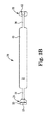
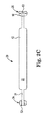
- Figure 2B is a top view and Figure 2C is a bottom view of the tool 20.
- the first guide 24 includes a first cylinder cradle 50 located on the top surface 40 of the tool 20 and a first tubing cradle 52 located on the bottom surface 42 of the tool 20.
- the second guide 26 includes a first cylinder cradle 60 located on the bottom surface 42 of the tool 20 and a second tubing cradle 62 located on the top surface 40 of the tool 20.
- the first guide 24 presents the first cylinder cradle 50 on the top surface 40 of the tool 20 and the second guide 26 presents the second cylinder cradle 60 on the bottom surface 42 of the tool 20.
- the first cylinder cradle 50 is on an opposite side of the tool 20 from the second cylinder cradle 60.
- other orientations of the cylinder cradles 50, 60 are also acceptable including placement of both cradles on the same surface of the tool 20.
- a size of the first tubing cradle 52 is substantially equal to a size of the second tubing cradle 62, which configures the cradles 52, 62 for engagement with the kink resistant tubing employed with penile prosthetic cylinders.
- each of the tubing cradles 52, 62 has about the same lateral width, and the lateral width is sized to receiving tubing having a width of about 5 mm in diameter.
- a lateral width 53 of the first cylinder cradle 50 ( Figure 2B ) is smaller (or narrower) than a lateral width 63 of the second cylinder cradle 60 ( Figure 2C ), which configures the first cylinder cradle 50 for engagement with narrow cylinders and configures the second cylinder cradle 60 for engagement with the standard, wider cylinders.
- Figure 3A is a side view and Figure 3B is an end view of the first guide 24.
- the first guide 24 is sized for insertion of a cylinder provided with a shallow tubing angle and includes a tubing angle TA1 between the first cylinder cradle 50 and the first tubing cradle 52 that is in a range between 0 - 35 degrees.
- One suitable tubing angle TA1 between the first cylinder cradle 50 and the first tubing cradle 52 is selected to be 22.5 degrees and is sized to accommodate a cylinder having shallow tubing angle.
- the tubing angle TA1 and the lateral width 53 of the first cylinder cradle 50 adapts the first guide 24 for engagement with narrow cylinders having shallow tubing angles.
- the neck 34 extending between the handle 22 and the first guide 24 is oriented at a non-zero neck angle NA relative to the handle 22 in a range from 0 - 45 degrees.
- Figure 4A is a side view of the tool 20 and Figure 4B is an end view of the second guide 26.
- the second guide 26 is sized for insertion of a cylinder provided with a broad tubing angle and includes a tubing angle TA between the second cylinder cradle 60 and the second tubing cradle 62 that is in a range between 35 - 70 degrees.
- One suitable tubing angle TA between the second cylinder cradle 60 and the second tubing cradle 62 is selected to be 45 degrees and is sized to accommodate a cylinder having a broad tubing angle.
- the broad tubing angle TA and the lateral width 63 of the second cylinder cradle 60 adapts the second guide 26 for engagement with standard diameter cylinders having broad tubing angles.
- the neck 36 extending between a handle 22 and the second guide 26 is oriented at an angle of about 0 degrees relative to the handle 22.
- the tool 20 includes a curved extension member 70 connected between the second neck 36 and the second guide 26 such that the second guide 26 is elevated or offset a distance away from the second side 42 of the tool 20.
- the tool 20 is suitably provided as a sterile, single use, disposable tool.
- Suitable materials for fabricating the tool 20 include plastics or metal.
- Suitable plastics for fabricating the tool 20 include polyethylene, high density polyethylene, polypropylene, acrylonitrile butadiene styrene (ABS), polyurethane, or the like. Fabricating the tool 20 from titanium or stainless steel is also acceptable.
- Figure 5A is a side view of one embodiment of a penile prosthesis system 100 including the tool 20 engaged with a cylinder 102 of a penile prosthesis.
- Figure 5B is a side view of the cylinder 102.
- a penile prosthesis usually includes a reservoir containing an amount of liquid, a pump provided to transfer the liquid to and from the cylinder, and two implantable cylinders (one for each corpora cavernosum).
- One suitable penile prosthesis is the Titan® OTR penile prosthesis that is provided with a one-touch release (OTR) pump, a reservoir, and two cylinders (either of standard diameter or of a narrow diameter).
- OTR one-touch release
- the Titan® OTR penile prosthesis is available from Coloplast Corp., Minneapolis, MN.
- the cylinder 102 includes an inflatable portion 104 connected to a proximal tip 106, and tubing 108 connected to the proximal tip 106 at a tubing junction 110.
- the cylinder 102 is of a style referred to as a narrow cylinder where the inflatable portion 104 has a diameter of about 12 mm prior to inflation and the tubing junction 110 forms a shallow tubing angle of about 22.5 degrees relative to the proximal tip 106.
- the first guide 24 of the tool 20 is engaged between the proximal tip 106 and the tubing junction 110.
- the first cylinder cradle 50 receives a portion of the proximal tip 106 and the first tubing cradle 52 engages with the tubing junction 110.
- the first guide 24 is controllably and positively engaged with the cylinder 102, which allows the surgeon to seat the proximal tip 106 fully and completely into the dilated crus penis, even if the crus is sclerotic.
- Figure 6 is a top schematic view of one embodiment of a kit 120 of parts.
- the kit 120 of parts includes packaging 122 containing a penile prosthesis 130, a tool 20 useful for implanting a portion of the penile prosthesis, and instructions 140 for use.
- the penile prosthesis 130 includes a pump 132 and a reservoir 134 that are adapted to be connected to the cylinder 102.
- the reservoir 134 contains a volume of liquid that is moved by the pump 132 into the cylinder 102 to inflate the cylinder and provide the patient with an erection.
- the tool 20 is the tool described above and includes a first guide 24 and a second guide 26 that are each sized to accommodate various sizes and configurations of cylinders.
- the instructions 140 for use describe procedures for inserting the proximal tip 106 of the cylinder 102 with the tool 20 into the crus penis.
- the kit 120 of parts includes the packaging 122 described above containing the penile prosthesis 130, a tool 200 described below that is provided with a suture protector 206, and instructions 140 for use in implanting the prosthesis 130 and in closing the incision with the suture protector 206.
- Figure 7 is a schematic view of one embodiment of the penile prosthesis system 100 readied for implantation in treatment of erectile dysfunction.
- the patient is suitably prepped for surgery and an incision is formed in the penis.
- the surgeon selects the appropriate incision, for example a penis-scrotal incision or another incision selected by the surgeon.
- Each corpus cavernosa of the penis is dilated in a distal direction, and the crus penis is dilated in a proximal direction.
- the distal tip of the cylinder 102 is directed through the incision in a distal direction along the dilated corpus cavernosum in the penis.
- the proximal tip 106 of the cylinder 102 is inserted into the crus penis by engaging the first guide 24 of the tool 20 between the tubing junction 110 and the cylinder 104.
- the first guide 24 fully engages with the region between the tubing junction 110 and the cylinder 104 to provide excellent leverage in inserting the proximal tip 106 into the crus penis.
- the pump 132 and the reservoir 134 are implanted into the patient.
- the pump 132 is desirably implanted into the scrotum
- the reservoir 134 is desirably implanted into a location in the abdomen, or other locations as selected by the surgeon.
- the pump 132 and the reservoir 134 are suitably connected to the tubing 108 of the cylinder 102 and the incisions are closed.
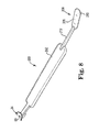
- Figure 8 is a perspective view of one embodiment of a tool 200 adapted for inserting a cylinder of a penile prosthesis into a patient and closing the incision formed to place the cylinder in the penis.
- the tool 200 includes a handle 202 extending between the first guide 24 on the first end portion of the tool and a suture protector 206 formed on a second end portion of the tool.
- the first guide 24 is as described above.
- the suture protector 206 is provided for placement between the skin of the penis and the cylinder implanted in the penis and functions to reduce the opportunity for the surgeon or other professional from undesirably contacting the inflatable cylinder with a suturing needle during closure of the incision.
- the suture protector 206 includes a flat suture plate 208 on a first side and a curved face 210 on a side opposite of the flat suture plate 208.
- the curved face 201 has a shape and curvature similar to the first cylinder cradle 50 of the first guide 24.
- a narrow neck 212 is connected between the handle 202 and the suture protector 206.
- the narrow neck 212 is sized to take up a minimum of space as the suture protector 206 is inside of the incision.
- the surgeon inserts the suture protector 206 into the incision and engages the curved face 210 with the inflatable portion 104 of the cylinder 102.
- the surgeon closes the incision in an appropriate manner up to a location near the narrow neck 212.
- the surgeon removes the suture protector 206 from the substantially closed incision and ties off the suture line.
- Embodiments provide a tool that is suited for properly seating the proximal tip of either a narrow cylinder or a standard broad cylinder into the crus penis, whether the crus suffers from sclerosis or not.
- the tool provides excellent engagement with the proximal tip by cradling a portion of the cylinder and a portion of the tubing. The combination of the engagement of these two surfaces results in a tool that achieves excellent engagement with the cylinder, which allows the tool to fully seat either a narrow cylinder or a broad cylinder deep into the crus penis.
Landscapes
- Health & Medical Sciences (AREA)
- Life Sciences & Earth Sciences (AREA)
- Surgery (AREA)
- General Health & Medical Sciences (AREA)
- Public Health (AREA)
- Biomedical Technology (AREA)
- Heart & Thoracic Surgery (AREA)
- Veterinary Medicine (AREA)
- Engineering & Computer Science (AREA)
- Animal Behavior & Ethology (AREA)
- Molecular Biology (AREA)
- Nuclear Medicine, Radiotherapy & Molecular Imaging (AREA)
- Medical Informatics (AREA)
- Reproductive Health (AREA)
- Vascular Medicine (AREA)
- Cardiology (AREA)
- Oral & Maxillofacial Surgery (AREA)
- Transplantation (AREA)
- Nursing (AREA)
- Orthopedic Medicine & Surgery (AREA)
- Prostheses (AREA)
- Orthopedics, Nursing, And Contraception (AREA)
Abstract
Description
- Implanted penile prostheses provide relief for men with erectile dysfunction.
- In a typical implantation procedure, the penis of the patient is incised to expose the two corpora cavernosa that are aligned axially in a side-by-side orientation within the penis. Each corpora cavernosum is dilated in a distal direction, for example by introducing gradually larger stainless steel rods into the corpora cavernosum until a space is created that is sized to receive a cylinder of the penile prosthesis. A similar dilation approach is taken in each branch of the crus penis in a proximal direction. Each of the cylinders is inserted into one of the dilated corpora cavernosa with a distal end of the cylinder inserted in the distal direction into the glans penis and a proximal end of the cylinder inserted in the proximal direction into the crus penis.
- Although the above-described approach has proven effective in treating erectile dysfunction, surgeons and their staff would welcome improvements in the tools and methods for inserting the proximal end of the cylinder into a narrowed or sclerotic crus penis.
- One aspect provides a tool adapted for inserting a cylinder of a penile prosthesis into a patient. The tool includes a handle extending between first and second guides. The first guide is located at a first end portion of the tool and includes a first cylinder cradle on a first side of the tool and a first tubing cradle on a second side of the tool that is opposite of the first side of the tool. The second guide located at a second end portion of the tool and includes a second cylinder cradle on one of the first side or the second side of the tool and a second tubing cradle on the other side of the tool. The size of the first tubing cradle is the same size as the second tubing cradle and a lateral width of the first cylinder cradle is smaller than a lateral width of the second cylinder cradle.
- One aspect provides a tool adapted for inserting a cylinder of a penile prosthesis into a patient. The tool includes a handle, a guide, and a suture protector. The handle extends on a longitudinal axis between a first end of the tool and an opposite second end of the tool. The guide is located at a first end portion of the tool and includes a first cylinder cradle on a first side of the tool and a first tubing cradle on a second side of the tool that is opposite of the first side of the tool. The suture protector is located at a second end portion of the tool. A lateral width of the first tubing cradle is less than a lateral width of the first cylinder cradle.
- The accompanying drawings are included to provide a further understanding of embodiments and are incorporated in and constitute a part of this specification. The drawings illustrate embodiments and together with the description serve to explain principles of embodiments. Other embodiments and many of the intended advantages of embodiments will be readily appreciated as they become better understood by reference to the following detailed description. The elements of the drawings are not necessarily to scale relative to each other. Like reference numerals designate corresponding similar parts.
-
Figure 1 is a perspective view of one embodiment of a tool adapted for inserting a cylinder of a penile prosthesis into a patient. -
Figure 2A is a side view of the tool illustrated inFigure 1 . -
Figure 2B is a top view of the tool illustrated inFigure 1 . -
Figure 2C is a bottom view of the tool illustrated inFigure 1 . -
Figure 3A is a side view of a first guide of the tool illustrated inFigure 1 . -
Figure 3B is an end view of the first guide illustrated inFigure 3A . -
Figure 4A is a side view of a second guide of the tool illustrated inFigure 1 . -
Figure 4B is an end view of the second guide illustrated inFigure 4A . -
Figure 5A is a side view of one embodiment of a penile prosthesis system including the tool illustrated inFigure 1 engaged with a cylinder of a penile prosthesis. -
Figure 5B is a side view of the cylinder illustrated inFigure 5A . -
Figure 6 is a top view of one embodiment of a kit of parts. -
Figure 7 is a schematic view of one embodiment of a penile prosthesis system employed in treating erectile dysfunction. -
Figure 8 is a perspective view of one embodiment of a tool adapted for inserting a cylinder of a penile prosthesis into a patient. - In the following Detailed Description, reference is made to the accompanying drawings that are a part of this application and illustrate various embodiments. In this regard, directional terminology, such as "top," "bottom," "front," "back," "leading," "trailing," etc., is used with reference to the orientation of the Figure(s) being described. Because components of embodiments can be positioned in a number of different orientations, the directional terminology is used for purposes of illustration and is in no way limiting. It is to be understood that other embodiments may be utilized and structural or logical changes may be made without departing from the scope of the invention. The following detailed description is not to be taken in a limiting sense, and the scope of the invention is defined by the appended claims.
- The features of the various exemplary embodiments described in this application may be combined with each other ("mixed and matched"), unless specifically noted otherwise.
- Soft tissue includes dermal tissue, sub-dermal tissue, ligaments, tendons, or membranes but does not include bone.
- The term "proximal" in this application means that part that is situated next to or near the point of attachment or origin or a central point; for example, as located toward a center of the human body. The crus penis is proximal relative to the patient.
- The term "distal" in this application means that part that is situated away from the point of attachment or origin or the central point; for example, as located away from the center of the human body. The glans penis is distal relative to the patient.
- End means endmost. A distal end is the furthest endmost location of a distal portion of a thing being described, whereas a proximal end is the nearest endmost location of a proximal portion of the thing being described. The portion next to or adjacent to an end is an end portion. For example, a 12 inch ruler has a center point at 6 inches, a first end at zero inches and a second, opposite end at 12 inches, an end portion from 1 inch to the first end and another end portion from 11 inches to the second end.
- Tubing angle means an angular dimension measured between a surface of a rear proximal tip of a cylinder of a penile prosthesis and a surface of tubing that extends away from the rear proximal tip. Some cylinders manufactured by Coloplast of Minneapolis, Minnesota are termed "zero degree tubing" cylinders and have a tubing angle of about zero degrees. Other cylinders manufactured by Coloplast have tubing angles of 22.5 degrees or 45 degrees, depending upon the application.
- Shallow tubing angle means a cylinder of a penile prosthesis having a tubing angle between the tubing and the cylinder in a range from 0 - 35 degrees.
- Broad tubing angle means a cylinder of a penile prosthesis having a tubing angle between the tubing and the cylinder in a range from 35 - 70 degrees.
- The typical penile prosthesis is implanted after suitably dilating the corpora cavernosa and the crus penis with a cavernatome or other dilation tool. Recently, surgeons have indicated a preference for implanting the proximal tip of the cylinder into the crus penis, when possible, without relying upon rear tip extenders or other parts added to the cylinder. A cylinder of the prosthesis is inserted into one of the corpora cavernosa by passing a needle/suture through the glans penis to direct/pull a distal end of the cylinder distally through the corpora cavernosum and into the glans penis. The proximal end of the cylinder is inserted and forced into the crus penis in an attempt to fully seat the cylinder in the crus at the root of the penis. Some patients have a well defined crus penis that is readily dilated to accept a standard diameter proximal tip of a cylinder. The surgeon will at times employ a forceps or other available tool to insert the proximal tip of the cylinder fully and completely into the well-dilated crus penis.
- Some patients have developed sclerosis in the crus penis that hinders the surgeon in fully seating the cylinder into the root of the penis. One solution to the issue of patients that present with sclerosis of the crus penis is to implant a cylinder having a narrower proximal tip than the standard diameter proximal tip. Surgeons have at times employed a forceps or other available tool to push the proximal tip of the cylinder fully and completely into the crus penis. However, this approach has the potential to undesirably perforate the wall of the inflatable cylinder, particularly when the crus penis has proven difficult to dilate.
- Embodiments provide a tool that is suited for properly seating the proximal tip of either an updated narrow cylinder or a standard broad cylinder into the crus penis. The tool is configured to provide excellent engagement with the proximal tip at a location where the tubing extends from the cylinder. The tool has a first engagement surface that cradles a portion of the cylinder and a second engagement surface that cradles a portion of the tubing. The combination of the engagement with these two surfaces of the cylinder results in a tool that achieves excellent engagement with the cylinder, which allows the tool to fully seat either a narrow cylinder or a broad cylinder deep into the crus penis.
-
Figure 1 is a perspective view of one embodiment of atool 20 adapted for inserting a cylinder of a penile prosthesis into a patient. Thetool 20 includes ahandle 22 extending between afirst guide 24 on a first end portion of the tool and asecond guide 26 on a second end portion of the tool. In one embodiment, thefirst guide 24 is different from thesecond guide 26, where thefirst guide 24 is sized for insertion of a cylinder having a shallow tubing angle and thesecond guide 26 is sized for insertion of a cylinder having a broad tubing angle. In one embodiment, thefirst guide 24 is different from thesecond guide 26, where thefirst guide 24 is sized for insertion of a narrow cylinder and thesecond guide 26 is sized for insertion of a standard broad cylinder. In this manner, thetool 20 is a combination tool well-suited for inserting cylinders of different sizes (depending upon the patient's anatomy) into the crus penis. - In one embodiment, the
handle 22 provides a wide ergonomic surface to allow for optimum control and thetool 20 includes afirst neck 34 extending between thehandle 22 and thefirst guide 24 and asecond neck 36 extending between thehandle 22 and thesecond guide 26. It is usually desirable for thefirst neck 34 to be narrower than thehandle 22 and for thesecond neck 36 to likewise be narrower than thehandle 22. -
Figure 2A is a side view of thetool 20. Thetool 20 includes a first surface 40 (or a top surface 40) and a second surface 42 (or a bottom surface 42). Thefirst guide 24 is located at a first end portion that defines a first end 44 of thetool 20 and thesecond guide 26 is located at a second end portion that defines asecond end 46 of thetool 20. -
Figure 2B is a top view andFigure 2C is a bottom view of thetool 20. Thefirst guide 24 includes afirst cylinder cradle 50 located on thetop surface 40 of thetool 20 and afirst tubing cradle 52 located on thebottom surface 42 of thetool 20. Thesecond guide 26 includes afirst cylinder cradle 60 located on thebottom surface 42 of thetool 20 and asecond tubing cradle 62 located on thetop surface 40 of thetool 20. With reference toFigure 2B andFigure 2C , thefirst guide 24 presents thefirst cylinder cradle 50 on thetop surface 40 of thetool 20 and thesecond guide 26 presents thesecond cylinder cradle 60 on thebottom surface 42 of thetool 20. Thus, in the illustrated embodiment, thefirst cylinder cradle 50 is on an opposite side of thetool 20 from thesecond cylinder cradle 60. However, other orientations of the cylinder cradles 50, 60 are also acceptable including placement of both cradles on the same surface of thetool 20. - In one embodiment, a size of the
first tubing cradle 52 is substantially equal to a size of thesecond tubing cradle 62, which configures thecradles lateral width 53 of the first cylinder cradle 50 (Figure 2B ) is smaller (or narrower) than a lateral width 63 of the second cylinder cradle 60 (Figure 2C ), which configures thefirst cylinder cradle 50 for engagement with narrow cylinders and configures thesecond cylinder cradle 60 for engagement with the standard, wider cylinders. -
Figure 3A is a side view andFigure 3B is an end view of thefirst guide 24. In one embodiment, thefirst guide 24 is sized for insertion of a cylinder provided with a shallow tubing angle and includes a tubing angle TA1 between thefirst cylinder cradle 50 and thefirst tubing cradle 52 that is in a range between 0 - 35 degrees. One suitable tubing angle TA1 between thefirst cylinder cradle 50 and thefirst tubing cradle 52 is selected to be 22.5 degrees and is sized to accommodate a cylinder having shallow tubing angle. The tubing angle TA1 and thelateral width 53 of thefirst cylinder cradle 50 adapts thefirst guide 24 for engagement with narrow cylinders having shallow tubing angles. - In one embodiment, the
neck 34 extending between thehandle 22 and thefirst guide 24 is oriented at a non-zero neck angle NA relative to thehandle 22 in a range from 0 - 45 degrees. -
Figure 4A is a side view of thetool 20 andFigure 4B is an end view of thesecond guide 26. In one embodiment, thesecond guide 26 is sized for insertion of a cylinder provided with a broad tubing angle and includes a tubing angle TA between thesecond cylinder cradle 60 and thesecond tubing cradle 62 that is in a range between 35 - 70 degrees. One suitable tubing angle TA between thesecond cylinder cradle 60 and thesecond tubing cradle 62 is selected to be 45 degrees and is sized to accommodate a cylinder having a broad tubing angle. The broad tubing angle TA and the lateral width 63 of thesecond cylinder cradle 60 adapts thesecond guide 26 for engagement with standard diameter cylinders having broad tubing angles. - In one embodiment, the
neck 36 extending between ahandle 22 and thesecond guide 26 is oriented at an angle of about 0 degrees relative to thehandle 22. - In one embodiment, the
tool 20 includes acurved extension member 70 connected between thesecond neck 36 and thesecond guide 26 such that thesecond guide 26 is elevated or offset a distance away from thesecond side 42 of thetool 20. - The
tool 20 is suitably provided as a sterile, single use, disposable tool. Suitable materials for fabricating thetool 20 include plastics or metal. Suitable plastics for fabricating thetool 20 include polyethylene, high density polyethylene, polypropylene, acrylonitrile butadiene styrene (ABS), polyurethane, or the like. Fabricating thetool 20 from titanium or stainless steel is also acceptable. -
Figure 5A is a side view of one embodiment of apenile prosthesis system 100 including thetool 20 engaged with acylinder 102 of a penile prosthesis.Figure 5B is a side view of thecylinder 102. - A penile prosthesis usually includes a reservoir containing an amount of liquid, a pump provided to transfer the liquid to and from the cylinder, and two implantable cylinders (one for each corpora cavernosum). One suitable penile prosthesis is the Titan® OTR penile prosthesis that is provided with a one-touch release (OTR) pump, a reservoir, and two cylinders (either of standard diameter or of a narrow diameter). The Titan® OTR penile prosthesis is available from Coloplast Corp., Minneapolis, MN.
- The
cylinder 102 includes aninflatable portion 104 connected to aproximal tip 106, andtubing 108 connected to theproximal tip 106 at atubing junction 110. Thecylinder 102 is of a style referred to as a narrow cylinder where theinflatable portion 104 has a diameter of about 12 mm prior to inflation and thetubing junction 110 forms a shallow tubing angle of about 22.5 degrees relative to theproximal tip 106. Thefirst guide 24 of thetool 20 is engaged between theproximal tip 106 and thetubing junction 110. In particular, thefirst cylinder cradle 50 receives a portion of theproximal tip 106 and thefirst tubing cradle 52 engages with thetubing junction 110. In this manner, thefirst guide 24 is controllably and positively engaged with thecylinder 102, which allows the surgeon to seat theproximal tip 106 fully and completely into the dilated crus penis, even if the crus is sclerotic. -
Figure 6 is a top schematic view of one embodiment of akit 120 of parts. Thekit 120 of parts includespackaging 122 containing apenile prosthesis 130, atool 20 useful for implanting a portion of the penile prosthesis, andinstructions 140 for use. Thepenile prosthesis 130 includes apump 132 and areservoir 134 that are adapted to be connected to thecylinder 102. Thereservoir 134 contains a volume of liquid that is moved by thepump 132 into thecylinder 102 to inflate the cylinder and provide the patient with an erection. Thetool 20 is the tool described above and includes afirst guide 24 and asecond guide 26 that are each sized to accommodate various sizes and configurations of cylinders. Theinstructions 140 for use describe procedures for inserting theproximal tip 106 of thecylinder 102 with thetool 20 into the crus penis. - In one embodiment, the
kit 120 of parts includes thepackaging 122 described above containing thepenile prosthesis 130, atool 200 described below that is provided with asuture protector 206, andinstructions 140 for use in implanting theprosthesis 130 and in closing the incision with thesuture protector 206. -
Figure 7 is a schematic view of one embodiment of thepenile prosthesis system 100 readied for implantation in treatment of erectile dysfunction. - The patient is suitably prepped for surgery and an incision is formed in the penis. The surgeon selects the appropriate incision, for example a penis-scrotal incision or another incision selected by the surgeon. Each corpus cavernosa of the penis is dilated in a distal direction, and the crus penis is dilated in a proximal direction. The distal tip of the
cylinder 102 is directed through the incision in a distal direction along the dilated corpus cavernosum in the penis. Theproximal tip 106 of thecylinder 102 is inserted into the crus penis by engaging thefirst guide 24 of thetool 20 between thetubing junction 110 and thecylinder 104. Thefirst guide 24 fully engages with the region between thetubing junction 110 and thecylinder 104 to provide excellent leverage in inserting theproximal tip 106 into the crus penis. - Subsequent to inserting the
cylinder 102 into the penis, thepump 132 and the reservoir 134 (Figure 6 ) are implanted into the patient. Thepump 132 is desirably implanted into the scrotum, and thereservoir 134 is desirably implanted into a location in the abdomen, or other locations as selected by the surgeon. Thepump 132 and thereservoir 134 are suitably connected to thetubing 108 of thecylinder 102 and the incisions are closed. -
Figure 8 is a perspective view of one embodiment of atool 200 adapted for inserting a cylinder of a penile prosthesis into a patient and closing the incision formed to place the cylinder in the penis. Thetool 200 includes ahandle 202 extending between thefirst guide 24 on the first end portion of the tool and asuture protector 206 formed on a second end portion of the tool. Thefirst guide 24 is as described above. Thesuture protector 206 is provided for placement between the skin of the penis and the cylinder implanted in the penis and functions to reduce the opportunity for the surgeon or other professional from undesirably contacting the inflatable cylinder with a suturing needle during closure of the incision. - The
suture protector 206 includes aflat suture plate 208 on a first side and acurved face 210 on a side opposite of theflat suture plate 208. The curved face 201 has a shape and curvature similar to thefirst cylinder cradle 50 of thefirst guide 24. In one embodiment, anarrow neck 212 is connected between thehandle 202 and thesuture protector 206. Thenarrow neck 212 is sized to take up a minimum of space as thesuture protector 206 is inside of the incision. - With additional reference to
Figure 7 , after placement of thecylinder 102 into the penis, the surgeon inserts thesuture protector 206 into the incision and engages thecurved face 210 with theinflatable portion 104 of thecylinder 102. The surgeon closes the incision in an appropriate manner up to a location near thenarrow neck 212. Thereafter, the surgeon removes thesuture protector 206 from the substantially closed incision and ties off the suture line. - Embodiments provide a tool that is suited for properly seating the proximal tip of either a narrow cylinder or a standard broad cylinder into the crus penis, whether the crus suffers from sclerosis or not. The tool provides excellent engagement with the proximal tip by cradling a portion of the cylinder and a portion of the tubing. The combination of the engagement of these two surfaces results in a tool that achieves excellent engagement with the cylinder, which allows the tool to fully seat either a narrow cylinder or a broad cylinder deep into the crus penis.
- Although specific embodiments have been illustrated and described herein, it will be appreciated by those of ordinary skill in the art that a variety of alternate and/or equivalent implementations may be substituted for the specific embodiments shown and described without departing from the scope of the present invention. This application is intended to cover any adaptations or variations of medical devices as discussed herein. Therefore, it is intended that this invention be limited only by the claims and the equivalents thereof.
Claims (16)
- A tool adapted for inserting a cylinder of a penile prosthesis into a patient, the tool comprising:a handle extending on a longitudinal axis between a first end of the tool and an opposite second end of the tool;a first guide located at a first end portion of the tool, the first guide including a first cylinder cradle on a first side of the tool and a first tubing cradle on a second side of the tool that is opposite of the first side of the tool; anda second guide located at a second end portion of the tool, the second guide including a second cylinder cradle on one of the first side and the second side of the tool and a second tubing cradle on an other of the first side and the second side of the tool;wherein a lateral width of the first tubing cradle is substantially equal to a lateral width of the second tubing cradle and a lateral width of the first cylinder cradle is smaller than a lateral width of the second cylinder cradle.
- The tool of claim 1, wherein the first side of the tool is a top side of the tool and the second side of the tool is a bottom side of the tool, with the first cylinder cradle located as an extension of the top side of the tool and the second cylinder cradle located as an extension of the bottom side of the tool.
- The tool of claim 1, wherein the first guide is configured for use with cylinders having a shallow tubing angle in which an angle between the first cylinder cradle and the first tubing cradle is in a range of 0 - 35 degrees and the second guide is configured for use with cylinders having a broad tubing angle in which an angle between the second cylinder cradle and the second tubing cradle is in a range of 35 - 70 degrees.
- The tool of claim 3, wherein the shallow tubing angle is sized to be 22.5 degrees and the broad tubing angle is sized to be 45 degrees.
- The tool of claim 1, further comprising:a first neck extending between the handle and the first guide and a second neck extending between the handle and the second guide, wherein a neck width of each of the first neck and the second neck is less than a lateral width of the handle.
- The tool of claim 5, wherein the neck width is less than the lateral width of the first tubing cradle and less than the lateral width of the first cylinder cradle.
- The tool of claim 5, wherein the first neck is oriented at a non-zero angle relative to the handle of the tool and the second neck is oriented at an angle of zero degrees relative to the handle of the tool.
- The tool of claim 7, further comprising:a curved extension member connected between the second neck and the second guide such that the second guide is elevated a distance away from the second side of the tool.
- The tool of claim 1, further comprising:a first neck extending between the handle and the first guide and a second neck extending between the handle and the second guide, wherein a neck width of each of the first neck and the second neck is less than a lateral width of the handle;wherein the first side of the tool is a top side of the tool and the second side of the tool is a bottom side of the tool, with the first cylinder cradle located as an extension of the top side of the tool and the second cylinder cradle located as an extension of the bottom side of the tool; andwherein the first neck is oriented at an obtuse angle in a direction away from the bottom side of the tool toward the top side of the tool and the second neck is oriented at an angle of zero degrees relative to the top side and the bottom side of the tool.
- The tool of claim 9, wherein the first guide is configured for use with cylinders having a shallow tubing angle and the second guide is configured for use with cylinders having a broad tubing angle such that an angle between the second cylinder cradle and the second tubing cradle is larger than an angle between the first cylinder cradle and the first tubing cradle.
- A penile prosthesis system comprising:a cylinder extending between a distal tip insertable into a glans penis and a proximal tip insertable into a crus penis; anda tool adapted for inserting the proximal tip of the cylinder into the crus penis, the tool comprising:a first guide located at a first end portion of the tool, the first guide including a first cylinder cradle on a first side of the tool and a first tubing cradle on a second side of the tool that is opposite of the first side of the tool; anda second guide located at a second end portion of the tool opposite of the first end portion of the tool, the second guide including a second cylinder cradle on one of the first side and the second side of the tool and a second tubing cradle on an other of the first side and the second side of the tool;wherein the first guide is configured for use with cylinders having a shallow tubing angle and the second guide is configured for use with cylinders having a broad tubing angle such that an angle between the second cylinder cradle and the second tubing cradle is larger than an angle between the first cylinder cradle and the first tubing cradle.
- The penile prosthesis system of claim 11, wherein a lateral width of the first tubing cradle is substantially equal to a lateral width of the second tubing cradle.
- The penile prosthesis system of claim 11, wherein the first side of the tool is a top side of the tool and the second side of the tool is a bottom side of the tool, with the first cylinder cradle located as an extension of the top side of the tool and the second cylinder cradle located as an extension of the bottom side of the tool.
- The penile prosthesis system of claim 11, further comprising:a handle extending between the first guide and the second guide; anda first neck extending between the handle and the first guide and a second neck extending between the handle and the second guide, wherein a neck width of each of the first neck and the second neck is less than a lateral width of the handle.
- The penile prosthesis system of claim 14, further comprising:a curved extension member connected between the second neck and the second guide such that the second guide is elevated a distance away from the second side of the tool.
- A kit of parts comprising:a penile prosthesis including a cylinder extending between a distal tip insertable into a glans penis and a proximal tip insertable into a crus penis;a tool adapted for inserting the proximal tip of the cylinder into the crus penis, the tool including a first guide and a second guide each located at opposite ends of the tool, the first guide including a first cylinder cradle on a first side of the tool and a first tubing cradle on a second side of the tool that is opposite of the first side of the tool, and the second guide including a second cylinder cradle on one of the first side and the second side of the tool and a second tubing cradle on an other of the first side and the second side of the tool; andinstructions for use describing the insertion of the proximal tip of the cylinder into the crus penis with the tool.
Priority Applications (1)
| Application Number | Priority Date | Filing Date | Title |
|---|---|---|---|
| EP16183340.5A EP3127489B1 (en) | 2014-04-16 | 2014-05-09 | Penile prosthesis insertion tool |
Applications Claiming Priority (1)
| Application Number | Priority Date | Filing Date | Title |
|---|---|---|---|
| US14/253,872 US9333079B2 (en) | 2014-04-16 | 2014-04-16 | Combination penile prosthesis insertion tool and system |
Related Child Applications (1)
| Application Number | Title | Priority Date | Filing Date |
|---|---|---|---|
| EP16183340.5A Division EP3127489B1 (en) | 2014-04-16 | 2014-05-09 | Penile prosthesis insertion tool |
Publications (2)
| Publication Number | Publication Date |
|---|---|
| EP2932908A1 true EP2932908A1 (en) | 2015-10-21 |
| EP2932908B1 EP2932908B1 (en) | 2016-08-17 |
Family
ID=50679937
Family Applications (2)
| Application Number | Title | Priority Date | Filing Date |
|---|---|---|---|
| EP14167705.4A Active EP2932908B1 (en) | 2014-04-16 | 2014-05-09 | Combination penile prosthesis insertion tool and system |
| EP16183340.5A Active EP3127489B1 (en) | 2014-04-16 | 2014-05-09 | Penile prosthesis insertion tool |
Family Applications After (1)
| Application Number | Title | Priority Date | Filing Date |
|---|---|---|---|
| EP16183340.5A Active EP3127489B1 (en) | 2014-04-16 | 2014-05-09 | Penile prosthesis insertion tool |
Country Status (3)
| Country | Link |
|---|---|
| US (2) | US9333079B2 (en) |
| EP (2) | EP2932908B1 (en) |
| ES (2) | ES2699350T3 (en) |
Families Citing this family (6)
| Publication number | Priority date | Publication date | Assignee | Title |
|---|---|---|---|---|
| US9333079B2 (en) * | 2014-04-16 | 2016-05-10 | Coloplast A/S | Combination penile prosthesis insertion tool and system |
| EP3150174B1 (en) | 2015-09-30 | 2021-08-11 | Coloplast A/S | A penile prosthetic with an insertion sleeve attachable to an inflatable bladder |
| USD931448S1 (en) | 2020-01-14 | 2021-09-21 | Coloplast A/S | Tool useful for implanting a penile prosthesis |
| US12471942B2 (en) | 2020-12-02 | 2025-11-18 | Coloplast A/S | Tool adapted to connect tubing of an implantable penile prosthesis |
| USD965142S1 (en) * | 2020-12-29 | 2022-09-27 | Coloplast A/S | Penile prosthesis tubing connector tool |
| USD1002845S1 (en) | 2021-12-01 | 2023-10-24 | Coloplast A/S | Penile prosthesis tubing connector tool |
Citations (5)
| Publication number | Priority date | Publication date | Assignee | Title |
|---|---|---|---|---|
| US5484450A (en) * | 1994-06-20 | 1996-01-16 | Mohamed; Adel W. | Penile prosthesis implant insertion instrument |
| WO2003071970A1 (en) * | 2002-02-22 | 2003-09-04 | Ams Research Corporation | Penile prosthesis implant insertion tool |
| US20040010244A1 (en) * | 2002-02-22 | 2004-01-15 | George Stephanie A. | Penile prosthesis implant insertion tool |
| WO2004045421A1 (en) * | 2002-11-14 | 2004-06-03 | Ams Research Corporation | Penile prosthesis and surgical instruments for implantation of penile prostheses |
| WO2011035787A1 (en) * | 2009-09-22 | 2011-03-31 | Coloplast A/S | Penile prosthesis, penile prosthesis insertion tool and system thereof |
Family Cites Families (15)
| Publication number | Priority date | Publication date | Assignee | Title |
|---|---|---|---|---|
| US1410296A (en) * | 1921-11-16 | 1922-03-21 | Hannah George Osborne | Vulcanite scraper |
| FR2090777A5 (en) * | 1970-12-01 | 1972-01-14 | Enzetti Eugenio | |
| US4244370A (en) | 1978-11-20 | 1981-01-13 | American Medical Systems, Inc. | Tool for positioning implantable medical prosthetic device _and method of using same |
| US4350151A (en) | 1981-03-12 | 1982-09-21 | Lone Star Medical Products, Inc. | Expanding dilator |
| US4628912A (en) | 1984-08-20 | 1986-12-16 | Fischell Robert | Adjustable root and tip extenders for the stiffener cylinder of a penile erection device |
| US4904183A (en) * | 1987-05-08 | 1990-02-27 | Unitek Corporation | Orthodontic debonding method and tool |
| US5056223A (en) | 1990-02-12 | 1991-10-15 | Helen Buck | Hand tool for de-coring cabbage heads |
| US5088925A (en) * | 1990-12-06 | 1992-02-18 | Mason William E | Instrument and method for administering an injectable anesthetic |
| DE4114311A1 (en) | 1991-05-02 | 1992-11-12 | Harald Heidmueller | EXTRACTOR |
| EP0682923A1 (en) | 1994-05-19 | 1995-11-22 | George Patrick Maxwell | Textured surface penile prosthetic device |
| US5968067A (en) | 1998-06-08 | 1999-10-19 | Mooreville; Michael | Surgical penile dilator instrument and method for its use |
| US6808489B2 (en) | 2002-05-24 | 2004-10-26 | Ams Research Corporation | Penile prosthesis with improved rear tip extender |
| US8192352B2 (en) | 2009-12-15 | 2012-06-05 | Coloplast A/S | Instrument configured to prepare a penis for implantation of a penile prosthetic |
| US8002692B2 (en) | 2009-12-16 | 2011-08-23 | Coloplast A/S | Method of preparing a penis for implantation of a penile prosthetic |
| US9333079B2 (en) * | 2014-04-16 | 2016-05-10 | Coloplast A/S | Combination penile prosthesis insertion tool and system |
-
2014
- 2014-04-16 US US14/253,872 patent/US9333079B2/en active Active
- 2014-05-09 ES ES16183340T patent/ES2699350T3/en active Active
- 2014-05-09 EP EP14167705.4A patent/EP2932908B1/en active Active
- 2014-05-09 EP EP16183340.5A patent/EP3127489B1/en active Active
- 2014-05-09 ES ES14167705.4T patent/ES2602952T3/en active Active
-
2016
- 2016-04-11 US US15/095,165 patent/US9757234B2/en active Active
Patent Citations (5)
| Publication number | Priority date | Publication date | Assignee | Title |
|---|---|---|---|---|
| US5484450A (en) * | 1994-06-20 | 1996-01-16 | Mohamed; Adel W. | Penile prosthesis implant insertion instrument |
| WO2003071970A1 (en) * | 2002-02-22 | 2003-09-04 | Ams Research Corporation | Penile prosthesis implant insertion tool |
| US20040010244A1 (en) * | 2002-02-22 | 2004-01-15 | George Stephanie A. | Penile prosthesis implant insertion tool |
| WO2004045421A1 (en) * | 2002-11-14 | 2004-06-03 | Ams Research Corporation | Penile prosthesis and surgical instruments for implantation of penile prostheses |
| WO2011035787A1 (en) * | 2009-09-22 | 2011-03-31 | Coloplast A/S | Penile prosthesis, penile prosthesis insertion tool and system thereof |
Also Published As
| Publication number | Publication date |
|---|---|
| ES2699350T3 (en) | 2019-02-08 |
| EP3127489A1 (en) | 2017-02-08 |
| US20160220374A1 (en) | 2016-08-04 |
| EP2932908B1 (en) | 2016-08-17 |
| ES2602952T3 (en) | 2017-02-23 |
| US20150297348A1 (en) | 2015-10-22 |
| EP3127489B1 (en) | 2018-08-22 |
| US9757234B2 (en) | 2017-09-12 |
| US9333079B2 (en) | 2016-05-10 |
Similar Documents
| Publication | Publication Date | Title |
|---|---|---|
| US8070675B2 (en) | Penile prosthesis cap and assembly | |
| US9757234B2 (en) | Tool adapted for inserting a penile prosthesis into a penis | |
| EP2480169B1 (en) | Penile prosthesis, penile prosthesis insertion tool and system thereof | |
| US10182914B2 (en) | Method of implanting a penile prosthetic with a tool having movable jaws | |
| US9480566B2 (en) | Tool with a groove useful for implanting a penile prosthetic cylinder | |
| EP2962665B1 (en) | Penile prosthesis cap | |
| EP2608744B1 (en) | Penile implant with convertible proximal tip | |
| US8360959B2 (en) | Penile implant with convertible proximal tip | |
| EP2944269B1 (en) | Locking needle for inflatable penile prosthesis | |
| US7985176B1 (en) | Method of implanting a penile prosthesis | |
| US9844393B2 (en) | Method of implanting a penile prosthetic | |
| US7942808B1 (en) | Method of implanting a penile prosthesis |
Legal Events
| Date | Code | Title | Description |
|---|---|---|---|
| PUAI | Public reference made under article 153(3) epc to a published international application that has entered the european phase |
Free format text: ORIGINAL CODE: 0009012 |
|
| 17P | Request for examination filed |
Effective date: 20140509 |
|
| AK | Designated contracting states |
Kind code of ref document: A1 Designated state(s): AL AT BE BG CH CY CZ DE DK EE ES FI FR GB GR HR HU IE IS IT LI LT LU LV MC MK MT NL NO PL PT RO RS SE SI SK SM TR |
|
| AX | Request for extension of the european patent |
Extension state: BA ME |
|
| GRAP | Despatch of communication of intention to grant a patent |
Free format text: ORIGINAL CODE: EPIDOSNIGR1 |
|
| INTG | Intention to grant announced |
Effective date: 20151208 |
|
| GRAS | Grant fee paid |
Free format text: ORIGINAL CODE: EPIDOSNIGR3 |
|
| GRAA | (expected) grant |
Free format text: ORIGINAL CODE: 0009210 |
|
| AK | Designated contracting states |
Kind code of ref document: B1 Designated state(s): AL AT BE BG CH CY CZ DE DK EE ES FI FR GB GR HR HU IE IS IT LI LT LU LV MC MK MT NL NO PL PT RO RS SE SI SK SM TR |
|
| REG | Reference to a national code |
Ref country code: GB Ref legal event code: FG4D |
|
| REG | Reference to a national code |
Ref country code: CH Ref legal event code: EP |
|
| REG | Reference to a national code |
Ref country code: IE Ref legal event code: FG4D |
|
| REG | Reference to a national code |
Ref country code: AT Ref legal event code: REF Ref document number: 820272 Country of ref document: AT Kind code of ref document: T Effective date: 20160915 |
|
| REG | Reference to a national code |
Ref country code: DE Ref legal event code: R096 Ref document number: 602014003035 Country of ref document: DE |
|
| REG | Reference to a national code |
Ref country code: NL Ref legal event code: MP Effective date: 20160817 |
|
| REG | Reference to a national code |
Ref country code: LT Ref legal event code: MG4D |
|
| REG | Reference to a national code |
Ref country code: AT Ref legal event code: MK05 Ref document number: 820272 Country of ref document: AT Kind code of ref document: T Effective date: 20160817 |
|
| PG25 | Lapsed in a contracting state [announced via postgrant information from national office to epo] |
Ref country code: LT Free format text: LAPSE BECAUSE OF FAILURE TO SUBMIT A TRANSLATION OF THE DESCRIPTION OR TO PAY THE FEE WITHIN THE PRESCRIBED TIME-LIMIT Effective date: 20160817 Ref country code: FI Free format text: LAPSE BECAUSE OF FAILURE TO SUBMIT A TRANSLATION OF THE DESCRIPTION OR TO PAY THE FEE WITHIN THE PRESCRIBED TIME-LIMIT Effective date: 20160817 Ref country code: HR Free format text: LAPSE BECAUSE OF FAILURE TO SUBMIT A TRANSLATION OF THE DESCRIPTION OR TO PAY THE FEE WITHIN THE PRESCRIBED TIME-LIMIT Effective date: 20160817 Ref country code: NL Free format text: LAPSE BECAUSE OF FAILURE TO SUBMIT A TRANSLATION OF THE DESCRIPTION OR TO PAY THE FEE WITHIN THE PRESCRIBED TIME-LIMIT Effective date: 20160817 Ref country code: RS Free format text: LAPSE BECAUSE OF FAILURE TO SUBMIT A TRANSLATION OF THE DESCRIPTION OR TO PAY THE FEE WITHIN THE PRESCRIBED TIME-LIMIT Effective date: 20160817 Ref country code: NO Free format text: LAPSE BECAUSE OF FAILURE TO SUBMIT A TRANSLATION OF THE DESCRIPTION OR TO PAY THE FEE WITHIN THE PRESCRIBED TIME-LIMIT Effective date: 20161117 |
|
| REG | Reference to a national code |
Ref country code: ES Ref legal event code: FG2A Ref document number: 2602952 Country of ref document: ES Kind code of ref document: T3 Effective date: 20170223 |
|
| PG25 | Lapsed in a contracting state [announced via postgrant information from national office to epo] |
Ref country code: SE Free format text: LAPSE BECAUSE OF FAILURE TO SUBMIT A TRANSLATION OF THE DESCRIPTION OR TO PAY THE FEE WITHIN THE PRESCRIBED TIME-LIMIT Effective date: 20160817 Ref country code: LV Free format text: LAPSE BECAUSE OF FAILURE TO SUBMIT A TRANSLATION OF THE DESCRIPTION OR TO PAY THE FEE WITHIN THE PRESCRIBED TIME-LIMIT Effective date: 20160817 Ref country code: GR Free format text: LAPSE BECAUSE OF FAILURE TO SUBMIT A TRANSLATION OF THE DESCRIPTION OR TO PAY THE FEE WITHIN THE PRESCRIBED TIME-LIMIT Effective date: 20161118 Ref country code: PL Free format text: LAPSE BECAUSE OF FAILURE TO SUBMIT A TRANSLATION OF THE DESCRIPTION OR TO PAY THE FEE WITHIN THE PRESCRIBED TIME-LIMIT Effective date: 20160817 Ref country code: PT Free format text: LAPSE BECAUSE OF FAILURE TO SUBMIT A TRANSLATION OF THE DESCRIPTION OR TO PAY THE FEE WITHIN THE PRESCRIBED TIME-LIMIT Effective date: 20161219 Ref country code: AT Free format text: LAPSE BECAUSE OF FAILURE TO SUBMIT A TRANSLATION OF THE DESCRIPTION OR TO PAY THE FEE WITHIN THE PRESCRIBED TIME-LIMIT Effective date: 20160817 |
|
| REG | Reference to a national code |
Ref country code: FR Ref legal event code: PLFP Year of fee payment: 4 |
|
| PG25 | Lapsed in a contracting state [announced via postgrant information from national office to epo] |
Ref country code: RO Free format text: LAPSE BECAUSE OF FAILURE TO SUBMIT A TRANSLATION OF THE DESCRIPTION OR TO PAY THE FEE WITHIN THE PRESCRIBED TIME-LIMIT Effective date: 20160817 Ref country code: EE Free format text: LAPSE BECAUSE OF FAILURE TO SUBMIT A TRANSLATION OF THE DESCRIPTION OR TO PAY THE FEE WITHIN THE PRESCRIBED TIME-LIMIT Effective date: 20160817 |
|
| REG | Reference to a national code |
Ref country code: DE Ref legal event code: R097 Ref document number: 602014003035 Country of ref document: DE |
|
| PG25 | Lapsed in a contracting state [announced via postgrant information from national office to epo] |
Ref country code: CZ Free format text: LAPSE BECAUSE OF FAILURE TO SUBMIT A TRANSLATION OF THE DESCRIPTION OR TO PAY THE FEE WITHIN THE PRESCRIBED TIME-LIMIT Effective date: 20160817 Ref country code: BE Free format text: LAPSE BECAUSE OF FAILURE TO SUBMIT A TRANSLATION OF THE DESCRIPTION OR TO PAY THE FEE WITHIN THE PRESCRIBED TIME-LIMIT Effective date: 20160817 Ref country code: BG Free format text: LAPSE BECAUSE OF FAILURE TO SUBMIT A TRANSLATION OF THE DESCRIPTION OR TO PAY THE FEE WITHIN THE PRESCRIBED TIME-LIMIT Effective date: 20161117 Ref country code: DK Free format text: LAPSE BECAUSE OF FAILURE TO SUBMIT A TRANSLATION OF THE DESCRIPTION OR TO PAY THE FEE WITHIN THE PRESCRIBED TIME-LIMIT Effective date: 20160817 Ref country code: SK Free format text: LAPSE BECAUSE OF FAILURE TO SUBMIT A TRANSLATION OF THE DESCRIPTION OR TO PAY THE FEE WITHIN THE PRESCRIBED TIME-LIMIT Effective date: 20160817 Ref country code: SM Free format text: LAPSE BECAUSE OF FAILURE TO SUBMIT A TRANSLATION OF THE DESCRIPTION OR TO PAY THE FEE WITHIN THE PRESCRIBED TIME-LIMIT Effective date: 20160817 |
|
| PLBE | No opposition filed within time limit |
Free format text: ORIGINAL CODE: 0009261 |
|
| STAA | Information on the status of an ep patent application or granted ep patent |
Free format text: STATUS: NO OPPOSITION FILED WITHIN TIME LIMIT |
|
| 26N | No opposition filed |
Effective date: 20170518 |
|
| PG25 | Lapsed in a contracting state [announced via postgrant information from national office to epo] |
Ref country code: SI Free format text: LAPSE BECAUSE OF FAILURE TO SUBMIT A TRANSLATION OF THE DESCRIPTION OR TO PAY THE FEE WITHIN THE PRESCRIBED TIME-LIMIT Effective date: 20160817 Ref country code: LU Free format text: LAPSE BECAUSE OF NON-PAYMENT OF DUE FEES Effective date: 20170531 |
|
| REG | Reference to a national code |
Ref country code: CH Ref legal event code: PL |
|
| PG25 | Lapsed in a contracting state [announced via postgrant information from national office to epo] |
Ref country code: MC Free format text: LAPSE BECAUSE OF FAILURE TO SUBMIT A TRANSLATION OF THE DESCRIPTION OR TO PAY THE FEE WITHIN THE PRESCRIBED TIME-LIMIT Effective date: 20160817 |
|
| REG | Reference to a national code |
Ref country code: IE Ref legal event code: MM4A |
|
| PG25 | Lapsed in a contracting state [announced via postgrant information from national office to epo] |
Ref country code: CH Free format text: LAPSE BECAUSE OF NON-PAYMENT OF DUE FEES Effective date: 20170531 Ref country code: LI Free format text: LAPSE BECAUSE OF NON-PAYMENT OF DUE FEES Effective date: 20170531 |
|
| REG | Reference to a national code |
Ref country code: FR Ref legal event code: PLFP Year of fee payment: 5 |
|
| PG25 | Lapsed in a contracting state [announced via postgrant information from national office to epo] |
Ref country code: LU Free format text: LAPSE BECAUSE OF NON-PAYMENT OF DUE FEES Effective date: 20170509 |
|
| PG25 | Lapsed in a contracting state [announced via postgrant information from national office to epo] |
Ref country code: IE Free format text: LAPSE BECAUSE OF NON-PAYMENT OF DUE FEES Effective date: 20170509 |
|
| PG25 | Lapsed in a contracting state [announced via postgrant information from national office to epo] |
Ref country code: MT Free format text: LAPSE BECAUSE OF NON-PAYMENT OF DUE FEES Effective date: 20170509 |
|
| PG25 | Lapsed in a contracting state [announced via postgrant information from national office to epo] |
Ref country code: AL Free format text: LAPSE BECAUSE OF FAILURE TO SUBMIT A TRANSLATION OF THE DESCRIPTION OR TO PAY THE FEE WITHIN THE PRESCRIBED TIME-LIMIT Effective date: 20160817 |
|
| PG25 | Lapsed in a contracting state [announced via postgrant information from national office to epo] |
Ref country code: HU Free format text: LAPSE BECAUSE OF FAILURE TO SUBMIT A TRANSLATION OF THE DESCRIPTION OR TO PAY THE FEE WITHIN THE PRESCRIBED TIME-LIMIT; INVALID AB INITIO Effective date: 20140509 |
|
| PG25 | Lapsed in a contracting state [announced via postgrant information from national office to epo] |
Ref country code: CY Free format text: LAPSE BECAUSE OF FAILURE TO SUBMIT A TRANSLATION OF THE DESCRIPTION OR TO PAY THE FEE WITHIN THE PRESCRIBED TIME-LIMIT Effective date: 20160817 |
|
| PG25 | Lapsed in a contracting state [announced via postgrant information from national office to epo] |
Ref country code: MK Free format text: LAPSE BECAUSE OF FAILURE TO SUBMIT A TRANSLATION OF THE DESCRIPTION OR TO PAY THE FEE WITHIN THE PRESCRIBED TIME-LIMIT Effective date: 20160817 |
|
| PG25 | Lapsed in a contracting state [announced via postgrant information from national office to epo] |
Ref country code: TR Free format text: LAPSE BECAUSE OF FAILURE TO SUBMIT A TRANSLATION OF THE DESCRIPTION OR TO PAY THE FEE WITHIN THE PRESCRIBED TIME-LIMIT Effective date: 20160817 |
|
| PG25 | Lapsed in a contracting state [announced via postgrant information from national office to epo] |
Ref country code: IS Free format text: LAPSE BECAUSE OF FAILURE TO SUBMIT A TRANSLATION OF THE DESCRIPTION OR TO PAY THE FEE WITHIN THE PRESCRIBED TIME-LIMIT Effective date: 20161217 |
|
| PGFP | Annual fee paid to national office [announced via postgrant information from national office to epo] |
Ref country code: DE Payment date: 20250529 Year of fee payment: 12 |
|
| PGFP | Annual fee paid to national office [announced via postgrant information from national office to epo] |
Ref country code: GB Payment date: 20250527 Year of fee payment: 12 Ref country code: ES Payment date: 20250602 Year of fee payment: 12 |
|
| PGFP | Annual fee paid to national office [announced via postgrant information from national office to epo] |
Ref country code: IT Payment date: 20250521 Year of fee payment: 12 |
|
| PGFP | Annual fee paid to national office [announced via postgrant information from national office to epo] |
Ref country code: FR Payment date: 20250526 Year of fee payment: 12 |