EP2932878B1 - Cleaning device that generates two suction flows - Google Patents
Cleaning device that generates two suction flows Download PDFInfo
- Publication number
- EP2932878B1 EP2932878B1 EP15163448.2A EP15163448A EP2932878B1 EP 2932878 B1 EP2932878 B1 EP 2932878B1 EP 15163448 A EP15163448 A EP 15163448A EP 2932878 B1 EP2932878 B1 EP 2932878B1
- Authority
- EP
- European Patent Office
- Prior art keywords
- flow
- suction
- cleaning device
- pressure
- air flow
- Prior art date
- Legal status (The legal status is an assumption and is not a legal conclusion. Google has not performed a legal analysis and makes no representation as to the accuracy of the status listed.)
- Active
Links
Images
Classifications
-
- F—MECHANICAL ENGINEERING; LIGHTING; HEATING; WEAPONS; BLASTING
- F04—POSITIVE - DISPLACEMENT MACHINES FOR LIQUIDS; PUMPS FOR LIQUIDS OR ELASTIC FLUIDS
- F04F—PUMPING OF FLUID BY DIRECT CONTACT OF ANOTHER FLUID OR BY USING INERTIA OF FLUID TO BE PUMPED; SIPHONS
- F04F5/00—Jet pumps, i.e. devices in which flow is induced by pressure drop caused by velocity of another fluid flow
- F04F5/02—Jet pumps, i.e. devices in which flow is induced by pressure drop caused by velocity of another fluid flow the inducing fluid being liquid
-
- A—HUMAN NECESSITIES
- A47—FURNITURE; DOMESTIC ARTICLES OR APPLIANCES; COFFEE MILLS; SPICE MILLS; SUCTION CLEANERS IN GENERAL
- A47L—DOMESTIC WASHING OR CLEANING; SUCTION CLEANERS IN GENERAL
- A47L5/00—Structural features of suction cleaners
- A47L5/12—Structural features of suction cleaners with power-driven air-pumps or air-compressors, e.g. driven by motor vehicle engine vacuum
- A47L5/16—Structural features of suction cleaners with power-driven air-pumps or air-compressors, e.g. driven by motor vehicle engine vacuum with suction devices other than rotary fans
- A47L5/18—Structural features of suction cleaners with power-driven air-pumps or air-compressors, e.g. driven by motor vehicle engine vacuum with suction devices other than rotary fans with ejectors, e.g. connected to motor vehicle exhaust
-
- A—HUMAN NECESSITIES
- A47—FURNITURE; DOMESTIC ARTICLES OR APPLIANCES; COFFEE MILLS; SPICE MILLS; SUCTION CLEANERS IN GENERAL
- A47L—DOMESTIC WASHING OR CLEANING; SUCTION CLEANERS IN GENERAL
- A47L5/00—Structural features of suction cleaners
- A47L5/12—Structural features of suction cleaners with power-driven air-pumps or air-compressors, e.g. driven by motor vehicle engine vacuum
- A47L5/22—Structural features of suction cleaners with power-driven air-pumps or air-compressors, e.g. driven by motor vehicle engine vacuum with rotary fans
-
- A—HUMAN NECESSITIES
- A47—FURNITURE; DOMESTIC ARTICLES OR APPLIANCES; COFFEE MILLS; SPICE MILLS; SUCTION CLEANERS IN GENERAL
- A47L—DOMESTIC WASHING OR CLEANING; SUCTION CLEANERS IN GENERAL
- A47L7/00—Suction cleaners adapted for additional purposes; Tables with suction openings for cleaning purposes; Containers for cleaning articles by suction; Suction cleaners adapted to cleaning of brushes; Suction cleaners adapted to taking-up liquids
- A47L7/0004—Suction cleaners adapted to take up liquids, e.g. wet or dry vacuum cleaners
- A47L7/0009—Suction cleaners adapted to take up liquids, e.g. wet or dry vacuum cleaners with means mounted on the nozzle; nozzles specially adapted for the recovery of liquid
-
- A—HUMAN NECESSITIES
- A47—FURNITURE; DOMESTIC ARTICLES OR APPLIANCES; COFFEE MILLS; SPICE MILLS; SUCTION CLEANERS IN GENERAL
- A47L—DOMESTIC WASHING OR CLEANING; SUCTION CLEANERS IN GENERAL
- A47L7/00—Suction cleaners adapted for additional purposes; Tables with suction openings for cleaning purposes; Containers for cleaning articles by suction; Suction cleaners adapted to cleaning of brushes; Suction cleaners adapted to taking-up liquids
- A47L7/0004—Suction cleaners adapted to take up liquids, e.g. wet or dry vacuum cleaners
- A47L7/0023—Recovery tanks
-
- A—HUMAN NECESSITIES
- A47—FURNITURE; DOMESTIC ARTICLES OR APPLIANCES; COFFEE MILLS; SPICE MILLS; SUCTION CLEANERS IN GENERAL
- A47L—DOMESTIC WASHING OR CLEANING; SUCTION CLEANERS IN GENERAL
- A47L9/00—Details or accessories of suction cleaners, e.g. mechanical means for controlling the suction or for effecting pulsating action; Storing devices specially adapted to suction cleaners or parts thereof; Carrying-vehicles specially adapted for suction cleaners
- A47L9/10—Filters; Dust separators; Dust removal; Automatic exchange of filters
- A47L9/14—Bags or the like; Rigid filtering receptacles; Attachment of, or closures for, bags or receptacles
- A47L9/1409—Rigid filtering receptacles
Definitions
- the invention relates to a cleaning device with an air flow generator for generating an air flow, which generate a first suction flow in a direction of flow of the air flow upstream of the air flow generator, opening into a first header first suction line and a pressure flow in a arranged in the flow direction of the air flow behind the air flow generator pressure line can.
- Such a cleaning device according to the preamble of claim 1 is in the EP-A1806086 disclosed.
- Such cleaning devices are known as dry or wet vacuum cleaners, as handheld devices or self-propelled robots.
- a mechanical air flow generator which is usually formed by an electric motor driven impeller, an air flow is generated. Upstream of the air flow generator forms a suction flow, through a suction line, solid or liquid particles can be absorbed by a surface and collected in a first collection. Downstream of the air flow generator, a pressure flow is formed, which usually leaves the device from an outlet device.
- the invention has for its object to further develop the cleaning device described above advantageous use and in particular to expand the range of use of the device with simple means.
- a second suction flow can be generated in addition to the first suction flow. While in the air flow generator in operation, the first suction flow flows through a first suction line, which opens into a first reservoir, flows through the second suction a second suction line, which opens into a second reservoir.
- hydrodynamic means provided with which the air flow of the air flow generator can generate the second suction flow.
- This preferably takes place in that the kinetic energy of the second suction flow can be obtained from the kinetic energy of the pressure flow.
- the kinetic energy of the second suction flow can be removed from the kinetic energy of the pressure flow.
- This is furthermore preferably carried out by means of a hydromechanical device, in particular a nozzle arrangement and particularly preferably a venturi nozzle arrangement.
- the air flow can be generated in a known manner by a mechanical air flow generator, for example by an impeller driven by an electric motor.
- the pressure flow generated by the air flow generator enters from a pressure outlet nozzle into a suction channel of a second cleaning unit, so that the pressure flow exits in the extension direction of the suction channel.
- the pulse of the pressure flow emerging from the pressure-flow outlet opening is transmitted to the air within the suction channel surrounding the pressure-flow outlet opening. Due to this impulse transmission, the second suction flow is formed.
- a first suction flow is generated with only one mechanical air flow generator, with which, for example, dry particles are taken up by a surface and conveyed into a collecting container.
- the air flow generated by the mechanical air flow generator kinetic energy is removed, so as to generate a second suction flow, for example, the wet particles, in particular droplets on a Surface removed to transport them in a second suction flow associated collecting container.
- the cleaning device according to the invention is particularly preferably designed as a self-propelled vacuum robot. It may be a floor mop, which has a pure water tank in which the water stored therein is used for humidifying a surface to be cleaned. The moisture can then be sucked out of the first or the second suction flow together with dirt particles dissolved in a moisture film. With the other suction flow is a dry cleaning.
- a conventional Venturi nozzle arrangement in which the hydromechanical principle is used, that the acceleration of a gas flow reduces the static pressure and that, as a result, a suction flow can be generated.
- the air flow generated by the air flow generator flows through a nozzle section into which the cross section of the pressure flow channel is reduced.
- a nozzle section with minimal cross-section opens a suction channel transversely to the air flow.
- the nozzle cross-section opens, so that the flow velocity of the air flow, which is maximum in the region of the mouth of the suction channel, can decrease.
- the invention can also be described in that a cleaning device with an air flow generator for generating an air flow is concerned, a first suction flow through a arranged in the flow direction of the air flow upstream of the air flow generator, opening into a first header first suction line and a pressure flow in a flow direction having the air flow behind the air flow generator arranged pressure line.
- means are provided, with which the air flow generates a second suction flow separated from the first suction flow through a second suction line opening into a second collecting tank.
- the kinetic energy of the second suction flow is obtained from the kinetic energy of the pressure flow.
- the cleaning device has a transverse to the flow direction of the pressure flow in a cross-section reduced area of the nozzle assembly opening of a second suction flow-conducting suction channel.
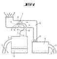
- FIG. 1 shows essentially elements of a cleaning unit, for example a self-propelled cleaning device in the form of a vacuum robot or a manually movable device.
- a first suction line 1 has at its free end a nozzle arrangement, not shown, for collecting moisture from a surface.
- the first suction line 1 opens into a first collecting container 2, in which the moisture can be separated from the air stream; For example, the droplets collect at the bottom of the first reservoir 2.
- a mechanical air flow generator 3 in the form of a rotary driven by an electric motor impeller generates upstream of the air flow generator 3, a suction flow S 1 , with said liquid particles are conveyed through the first suction line 1.
- a pressure line 4 In the flow direction of the air flow behind the air flow generator 3 is a pressure line 4, through which the air flow generated by the air flow generator 3 is conveyed as a pressure flow D in a nozzle channel 10.
- the nozzle channel 10 terminates in a pressure flow outlet opening 9, through which the pressure flow D enters a mixing zone 14 of a suction channel 12.
- the nozzle channel 10 extends parallel to the extension direction of the suction channel 12 and in the embodiment in its cross-sectional center.
- the emerging from the pressure flow outlet opening 9 air transfers its momentum in the mixing zone 14 partially to the local air, so that in the suction channel 12 parallel to the emerging from the pressure flow outlet opening 9 compressed air flow directed second suction flow.
- the suction channel 12 is connected to a second collecting container 6, in which a second suction line 5 opens.
- the free end of the second suction line 5 is provided with a nozzle arrangement for absorbing solid particles from a surface to be cleaned.
- the second suction line 5 is flowed through by the second suction stream S 2 .
- Dust filters, dust bags or the like may be arranged inside the second collecting container 6 in order to filter out the particles in the second suction stream S 2 from the air stream.
- a dust filter 11 is shown at the inlet opening of the suction channel 12.
- the air flow generated by the air flow generator 3 mixes in the mixing zone 14 with the second suction flow S 2 .
- the entire exhaust air flows out through an outlet opening 8 from the cleaning device.
- the reference numeral 13 denotes a fresh water tank; stored therein fresh water can be used for a wiper device and sucked on the suction line 1.
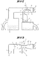
- FIG. 2 Also shown only schematically device also shows the technical elements relevant to the invention of a cleaning device, such as a self-propelled robot or manually movable device.
- a second suction stream S 2 is generated by means of a nozzle assembly 7 from the pressure flow D generated by an air flow generator 3.
- the pressure flow D is passed through a parallel to a suction channel 12, in the middle of its cross-section nozzle channel 10 into a mixing zone 14 of the suction channel 12, so that upstream of the mixing zone 14, a second suction flow S 2 is formed.
- the first suction line 1 through which the first suction flow S 1 directly generated by the air flow generator 3 flows, but connected to a collecting container 2, are deposited in the dry particles.
- the second suction line 5, through which the second suction stream S 2 flows, is connected in this embodiment with a collecting container 6, in which liquid can collect.
- a fresh water tank 13 is provided so that the device can operate as a wiper device.
- FIG. 3 schematically shows the structure of a classic Venturi nozzle, which in the embodiments according to the FIGS. 1 and 2 can be used instead of the nozzle assembly shown there.
- a pressure line 4 which is located downstream of the mechanical air flow generator 3, a pressure flow D.
- a first nozzle portion 15 of the nozzle assembly 7 decreases due to a conical wall of the nozzle portion 15, the cross-sectional area of the pressure line 4, so that the speed of the pressure flow D. elevated. With this increased speed, the pressure flow D passes through a second nozzle section 15 'with a constant cross-sectional area.
- this second nozzle portion 15 ' is a transverse to the flow direction of the pressure flow D extending orifice 12' of a suction channel 12, in which a second suction flow S2 is formed.
- the second nozzle section 15 ' is adjoined by a third nozzle section 15 ", which likewise has cone-shaped nozzle channel walls, so that the cross section of the third nozzle section 15" increases continuously in the flow direction, resulting in a steady decrease in the flow velocity.
- the third nozzle section 15 forms a mixing zone 14, to which an outlet opening 8 adjoins.
- a cleaning device which is characterized in that the kinetic energy of the second suction flow S 2 is obtained from the kinetic energy of the pressure flow D.
- a cleaning device which is characterized in that the means have a nozzle arrangement, wherein the pressure line 4 and a second suction flow S 2 conducting suction channel 12 into the nozzle assembly 7, in particular a Venturi nozzle arrangement, open.
- a cleaning device which is characterized in that a pressure flow outlet nozzle 9 opens into the suction passage 12 which guides the second suction flow S 2 , through which the pressure flow D emerges in the extension direction of the suction passage 12.
- a cleaning device which is characterized by a transversely to the flow direction of the pressure flow D in a reduced cross-section area 15 'of the nozzle assembly 7 opening 12' of the second suction flow S 2 conducting suction channel 12th
- a cleaning device which is characterized in that one of the first and second collecting container 2, 6 for separating dry particles from the first or second suction stream S 1 , S 2 is provided and the respective other collecting container 6, 2 for the separation of droplets from the each other suction stream S 2 , S 1 is provided.
- a cleaning device which is characterized in that the cleaning device is a self-propelled vacuum cleaner.
Description
Die Erfindung betrifft ein Reinigungsgerät mit einem Luftstromerzeuger zur Erzeugung eines Luftstroms, der einen ersten Saugstrom in einer in Strömungsrichtung des Luftstroms vor dem Luftstromerzeuger angeordnete, in einen ersten Sammelbehälter mündenden ersten Saugleitung und einen Druckstrom in einer in Strömungsrichtung des Luftstroms hinter dem Luftstromerzeuger angeordneten Druckleitung erzeugen kann.The invention relates to a cleaning device with an air flow generator for generating an air flow, which generate a first suction flow in a direction of flow of the air flow upstream of the air flow generator, opening into a first header first suction line and a pressure flow in a arranged in the flow direction of the air flow behind the air flow generator pressure line can.
Ein derartiges Reinigungsgerät gemäß dem Oberbegriff von Anspruch 1 ist in der
Derartige Reinigungsgeräte sind als Trocken- oder Nassstaubsauger, als Handgeräte oder selbstfahrende Roboter bekannt. Mit einem mechanischen Luftstromerzeuger, der im Regelfall von einem elektromotorisch angetriebenen Gebläserad ausgebildet wird, wird ein Luftstrom erzeugt. Stromaufwärts des Luftstromerzeugers bildet sich ein Saugstrom aus, durch eine Saugleitung können feste oder flüssige Partikel von einer Oberfläche aufgesaugt werden und in einem ersten Sammelbehälter gesammelt werden. Stromabwärts des Luftstromerzeugers bildet sich ein Druckstrom aus, der zumeist aus einer Austrittseinrichtung das Gerät verlässt.Such cleaning devices are known as dry or wet vacuum cleaners, as handheld devices or self-propelled robots. With a mechanical air flow generator, which is usually formed by an electric motor driven impeller, an air flow is generated. Upstream of the air flow generator forms a suction flow, through a suction line, solid or liquid particles can be absorbed by a surface and collected in a first collection. Downstream of the air flow generator, a pressure flow is formed, which usually leaves the device from an outlet device.
Der Erfindung liegt die Aufgabe zugrunde, das eingangs beschriebene Reinigungsgerät gebrauchsvorteilhaft weiterzubilden und insbesondere mit einfachen Mitteln das Gebrauchsspektrum des Gerätes zu erweitern. Zur Lösung der Aufgabe wird zunächst und im Wesentlichen vorgeschlagen, dass ergänzend zu dem ersten Saugstrom ein zweiter Saugstrom erzeugt werden kann. Während bei im Betrieb befindlichen Luftstromerzeuger der erste Saugstrom durch eine erste Saugleitung strömt, die in einem ersten Sammelbehälter mündet, durchströmt der zweite Saugstrom eine zweite Saugleitung, die in einen zweiten Sammelbehälter mündet.The invention has for its object to further develop the cleaning device described above advantageous use and in particular to expand the range of use of the device with simple means. To solve the problem, it is initially and essentially proposed that a second suction flow can be generated in addition to the first suction flow. While in the air flow generator in operation, the first suction flow flows through a first suction line, which opens into a first reservoir, flows through the second suction a second suction line, which opens into a second reservoir.
Es sind Mittel, insbesondere hydrodynamische Mittel, vorgesehen, mit denen der Luftstrom des Luftstromerzeugers den zweiten Saugstrom erzeugen kann. Dies erfolgt bevorzugt dadurch, dass die kinetische Energie des zweiten Saugstroms aus der kinetischen Energie des Druckstroms gewinnbar ist. Die kinetische Energie des zweiten Saugstroms kann der kinetischen Energie des Druckstroms entzogen werden. Dies erfolgt weiter bevorzugt mittels einer hydromechanischen Vorrichtung, insbesondere einer Düsenanordnung und besonders bevorzugt einer Venturi-Düsenanordnung.There are means, in particular hydrodynamic means, provided with which the air flow of the air flow generator can generate the second suction flow. This preferably takes place in that the kinetic energy of the second suction flow can be obtained from the kinetic energy of the pressure flow. The kinetic energy of the second suction flow can be removed from the kinetic energy of the pressure flow. This is furthermore preferably carried out by means of a hydromechanical device, in particular a nozzle arrangement and particularly preferably a venturi nozzle arrangement.
Die Druckleitung und ein Saugkanal, wobei der Saugkanal mit einer zweiten Saugleitung in Strömungsverbindung steht, münden in die Düsenanordnung.The pressure line and a suction channel, wherein the suction channel is in flow communication with a second suction line, open into the nozzle assembly.
Der Luftstrom kann in bekannter Weise von einem mechanischen Luftstromerzeuger, beispielsweise von einem von einem Elektromotor angetriebenen Gebläserad erzeugt werden. Der von dem Luftstromerzeuger erzeugte Druckstrom tritt aus einer Druckaustrittsdüse in einen Saugkanal eines zweiten Reinigungsaggregates ein, so dass der Druckstrom in Erstreckungsrichtung des Saugkanales austritt. Der Impuls des aus der Druckstrom-Austrittsöffnung heraustretenden Druckstroms wird auf die Luft innerhalb des die Druckstrom-Austrittsöffnung umgebenden Saugkanals übertragen. Aufgrund dieser Impulsübertragung bildet sich der zweite Saugstrom aus.The air flow can be generated in a known manner by a mechanical air flow generator, for example by an impeller driven by an electric motor. The pressure flow generated by the air flow generator enters from a pressure outlet nozzle into a suction channel of a second cleaning unit, so that the pressure flow exits in the extension direction of the suction channel. The pulse of the pressure flow emerging from the pressure-flow outlet opening is transmitted to the air within the suction channel surrounding the pressure-flow outlet opening. Due to this impulse transmission, the second suction flow is formed.
Erfindungsgemäß wird somit mit nur einem mechanischen Luftstromerzeuger ein erster Saugstrom erzeugt, mit dem beispielsweise trockene Partikel von einer Oberfläche aufgenommen werden und in einen Sammelbehälter befördert werden. Dem von dem mechanischen Luftstromerzeuger erzeugten Luftstrom wird Bewegungsenergie entnommen, um damit einen zweiten Saugstrom zu erzeugen, der beispielsweise feuchte Partikel, insbesondere Tröpfchen, an einer Oberfläche entfernt, um sie in einen dem zweiten Saugstrom zugeordneten Sammelbehälter zu transportieren.According to the invention, therefore, a first suction flow is generated with only one mechanical air flow generator, with which, for example, dry particles are taken up by a surface and conveyed into a collecting container. The air flow generated by the mechanical air flow generator kinetic energy is removed, so as to generate a second suction flow, for example, the wet particles, in particular droplets on a Surface removed to transport them in a second suction flow associated collecting container.
Es ist aber auch vorgesehen, dass mit dem ersten Saugstrom, der unmittelbar von dem Luftstromerzeuger erzeugt wird, Feuchtigkeit aufgenommen wird und mit dem durch eine Düsenanordnung erzeugten zweiten Saugstrom trockene Partikel aufgesammelt werden.However, it is also provided that moisture is absorbed by the first suction flow, which is generated directly by the air flow generator, and dry particles are collected with the second suction flow generated by a nozzle arrangement.
Hinsichtlich des Transports der feuchten oder flüssigen Partikel unter Verwendung von Saugdüsen, Saugschläuchen oder dergleichen kann auf bekannte und bewährte Technologien zurückgegriffen werden. Auch das Ausfiltern der flüssigen oder festen Partikel aus dem ersten oder dem zweiten Saugstrom erfolgt mit den bekannten Vorrichtungen, beispielsweise Staubbeuteln, Staubfiltern oder mittels Schwerkraft oder einer Zentrifugalkraft.Regarding the transport of the wet or liquid particles using suction nozzles, suction hoses or the like, known and proven technologies can be used. The filtering out of the liquid or solid particles from the first or the second suction stream also takes place with the known devices, for example dust bags, dust filters or by means of gravity or a centrifugal force.
Das erfindungsgemäße Reinigungsgerät ist besonders bevorzugt als selbstfahrender Saugroboter ausgebildet. Es kann sich dabei um ein Bodenwischgerät handeln, welches einen Reinwassertank aufweist, bei dem das darin bevorratete Wasser zur Befeuchtung einer zu reinigenden Oberfläche verwendet wird. Die Feuchtigkeit kann dann zusammen mit in einem Feuchtigkeitsfilm gelösten Schmutzpartikeln von dem ersten oder dem zweiten Saugstrom abgesaugt werden. Mit dem jeweils anderen Saugstrom erfolgt eine Trockenreinigung. Zur Erzeugung des zweiten Saugstroms kann eine klassische Venturi-Düsenanordnung verwendet werden, bei der das hydromechanische Prinzip zur Anwendung kommt, dass sich bei einer Beschleunigung eines Gasstroms der statische Druck vermindert und dass dadurch eine Saugströmung erzeugt werden kann. Bei einer derartigen Venturi-Düse durchströmt der von dem Luftstromerzeuger erzeugte Luftstrom einen Düsenabschnitt, in den sich der Querschnitt des Druckstromkanals vermindert. In einen Düsenabschnitt mit minimalem Querschnitt mündet quer zur Luftströmung ein Saugkanal. In Strömungsrichtung hinter dem Saugkanal öffnet sich der Düsenquerschnitt, so dass sich die Strömungsgeschwindigkeit der Luftströmung, die im Bereich der Mündung des Saugkanales maximal ist, vermindern kann.The cleaning device according to the invention is particularly preferably designed as a self-propelled vacuum robot. It may be a floor mop, which has a pure water tank in which the water stored therein is used for humidifying a surface to be cleaned. The moisture can then be sucked out of the first or the second suction flow together with dirt particles dissolved in a moisture film. With the other suction flow is a dry cleaning. In order to generate the second suction flow, it is possible to use a conventional Venturi nozzle arrangement in which the hydromechanical principle is used, that the acceleration of a gas flow reduces the static pressure and that, as a result, a suction flow can be generated. In such a Venturi nozzle, the air flow generated by the air flow generator flows through a nozzle section into which the cross section of the pressure flow channel is reduced. In a nozzle section with minimal cross-section opens a suction channel transversely to the air flow. In the flow direction behind the suction channel, the nozzle cross-section opens, so that the flow velocity of the air flow, which is maximum in the region of the mouth of the suction channel, can decrease.
Die Erfindung kann auch dahingehend beschrieben werden, dass ein Reinigungsgerät mit einem Luftstromerzeuger zur Erzeugung eines Luftstroms betroffen ist, der einen ersten Saugstrom durch eine in Strömungsrichtung des Luftstroms vor dem Luftstromerzeuger angeordnete, in einen ersten Sammelbehälter mündenden ersten Saugleitung und einen Druckstrom in einer in Strömungsrichtung des Luftstroms hinter dem Luftstromerzeuger angeordneten Druckleitung aufweist. Zur Lösung kann vorgesehen sein, dass Mittel vorgesehen sind, mit denen der Luftstrom einen vom ersten Saugstrom getrennten zweiten Saugstrom durch eine in einen zweiten Sammelbehälter mündende zweite Saugleitung erzeugt.The invention can also be described in that a cleaning device with an air flow generator for generating an air flow is concerned, a first suction flow through a arranged in the flow direction of the air flow upstream of the air flow generator, opening into a first header first suction line and a pressure flow in a flow direction having the air flow behind the air flow generator arranged pressure line. To solve it can be provided that means are provided, with which the air flow generates a second suction flow separated from the first suction flow through a second suction line opening into a second collecting tank.
Bevorzugt ist, dass die kinetische Energie des zweiten Saugstroms aus der kinetischen Energie des Druckstroms gewonnen wird.It is preferred that the kinetic energy of the second suction flow is obtained from the kinetic energy of the pressure flow.
Es kann vorgesehen sein, dass das Reinigungsgerät eine quer zur Strömungsrichtung des Druckstroms in einen querschnittsverminderten Bereich der Düsenanordnung mündende Öffnung eines den zweiten Saugstrom leitenden Saugkanals aufweist.It can be provided that the cleaning device has a transverse to the flow direction of the pressure flow in a cross-section reduced area of the nozzle assembly opening of a second suction flow-conducting suction channel.
Ausführungsbeispiele der Erfindung werden nachfolgend anhand beigefügter Zeichnungen erläutert. Es zeigen:
- Fig. 1
- schematisch den Aufbau eines ersten Ausführungsbeispieles,
- Fig. 2
- schematisch den Aufbau eines zweiten Ausführungsbeispieles und
- Fig. 3
- schematisch den Aufbau einer klassischen Venturi-Düse, die in einer der in den
Figuren 12 dargestellten Ausführungsbeispielen zur Anwendung kommen kann.
- Fig. 1
- schematically the structure of a first embodiment,
- Fig. 2
- schematically the structure of a second embodiment and
- Fig. 3
- schematically the construction of a classic Venturi nozzle, which in one of the
FIGS. 1 and2 illustrated embodiments may be used.
Die
In Strömungsrichtung des Luftstroms hinter dem Luftstromerzeuger 3 befindet sich eine Druckleitung 4, durch die der vom Luftstromerzeuger 3 erzeugte Luftstrom als Druckstrom D in einen Düsenkanal 10 befördert wird. Der Düsenkanal 10 endet in einer Druckstrom-Austrittsöffnung 9, durch die der Druckstrom D in eine Mischzone 14 eines Saugkanals 12 tritt. Der Düsenkanal 10 erstreckt sich parallel zur Erstreckungsrichtung des Saugkanals 12 und im Ausführungsbeispiel in dessen Querschnittsmitte. Die aus der Druckstrom-Austrittsöffnung 9 heraustretende Luft überträgt ihren Impuls in der Mischzone 14 teilweise an die dortige Luft, so dass sich im Saugkanal 12 eine parallel zum aus der Druckstrom-Austrittsöffnung 9 austretenden Druckluftstrom gerichtete zweite Saugströmung ausbildet.In the flow direction of the air flow behind the
Der Saugkanal 12 ist mit einem zweiten Sammelbehälter 6 verbunden, in dem eine zweite Saugleitung 5 mündet. Das freie Ende der zweiten Saugleitung 5 ist mit einer Düsenanordnung versehen, um feste Partikel von einer zu reinigenden Oberfläche aufzusaugen. Die zweite Saugleitung 5 wird vom zweiten Saugstrom S2 durchströmt.The
Innerhalb des zweiten Sammelbehälters 6 können Staubfilter, Staubbeutel oder dergleichen angeordnet sein, um die im zweiten Saugstrom S2 befindlichen Partikel aus dem Luftstrom herauszufiltern. Der Übersichtlichkeit halber ist in der
Der vom Luftstromerzeuger 3 erzeugte Luftstrom mischt sich in der Mischzone 14 mit dem zweiten Saugstrom S2. Die gesamte Abluft strömt durch eine Austrittsöffnung 8 aus dem Reinigungsgerät heraus. Mit der Bezugsziffer 13 ist ein Frischwassertank bezeichnet; das darin bevorratete Frischwasser kann für eine Wischvorrichtung verwendet werden und über die Saugleitung 1 aufgesaugt werden.The air flow generated by the
Die in der
Die zweite Saugleitung 5, durch die der zweite Saugstrom S2 strömt, ist bei diesem Ausführungsbeispiel mit einem Sammelbehälter 6 verbunden, in dem sich Flüssigkeit sammeln kann. Auch hier ist ein Frischwassertank 13 vorgesehen, so dass die Vorrichtung als Wischvorrichtung arbeiten kann.The
Die
Die vorstehenden Ausführungen dienen der Erläuterung der von der Anmeldung insgesamt erfassten Erfindungen, die den Stand der Technik zumindest durch die folgenden Merkmalskombinationen jeweils eigenständig weiterbilden, nämlich:
- Ein Reinigungsgerät, das dadurch gekennzeichnet ist, dass Mittel vorgesehen sind, mit denen der Luftstrom einen vom ersten Saugstrom S1 getrennten zweiten Saugstrom S2 durch eine in einen zweiten Sammelbehälter 6 mündende zweite Saugleitung 5 erzeugt.
- A cleaning device, which is characterized in that means are provided, with which the air flow generates a second suction flow S 2 separated from the first suction flow S 1 by a
second suction line 5 opening into asecond collecting container 6.
Ein Reinigungsgerät, das dadurch gekennzeichnet ist, dass die kinetische Energie des zweiten Saugstroms S2 aus der kinetischen Energie des Druckstroms D gewonnen wird.A cleaning device, which is characterized in that the kinetic energy of the second suction flow S 2 is obtained from the kinetic energy of the pressure flow D.
Ein Reinigungsgerät, das dadurch gekennzeichnet ist, dass die Mittel eine Düsenanordnung aufweisen, wobei die Druckleitung 4 und ein den zweiten Saugstrom S2 leitender Saugkanal 12 in die Düsenanordnung 7, insbesondere eine Venturi-Düsenanordnung, münden.A cleaning device, which is characterized in that the means have a nozzle arrangement, wherein the
Ein Reinigungsgerät, das dadurch gekennzeichnet ist, dass eine Druckstrom-Austrittsdüse 9 in den den zweiten Saugstrom S2 leitenden Saugkanal 12 mündet, durch welche der Druckstrom D in Erstreckungsrichtung des Saugkanals 12 austritt.A cleaning device, which is characterized in that a pressure
Ein Reinigungsgerät, das gekennzeichnet ist durch eine quer zur Strömungsrichtung des Druckstroms D in einen querschnittsverminderten Bereich 15' der Düsenanordnung 7 mündende Öffnung 12' eines den zweiten Saugstrom S2 leitenden Saugkanals 12.A cleaning device, which is characterized by a transversely to the flow direction of the pressure flow D in a reduced cross-section area 15 'of the
Ein Reinigungsgerät, das dadurch gekennzeichnet ist, dass einer der ersten und zweiten Sammelbehälter 2, 6 zum Abscheiden von trockenen Partikeln aus dem ersten oder zweiten Saugstrom S1, S2 vorgesehen ist und der jeweils andere Sammelbehälter 6, 2 zum Abscheiden von Tröpfchen aus dem jeweils anderen Saugstrom S2, S1 vorgesehen ist.A cleaning device, which is characterized in that one of the first and
Ein Reinigungsgerät, das dadurch gekennzeichnet ist, dass das Reinigungsgerät ein selbstfahrender Saugroboter ist.
Claims (7)
- A cleaning device comprising an air flow generator (3) for generating an air flow, which can generate a first suction flow (S1) in a first suction line (1), which is arranged in flow direction of the air flow upstream of the air flow generator (3) and which leads into a first collecting container (2), and a pressure flow (D) in a pressure line (4), which is arranged in flow direction of the air flow downstream from the air flow generator (3), characterized in that provision is made for means, by means of which the air flow can generate a second suction flow (S2), which is separated from the first suction flow (S1), through a second suction line (5), which leads into a second collecting container (6).
- The cleaning device according to claim 1, characterized in that the kinetic energy of the second suction flow (S2) can be gained from the kinetic energy of the pressure flow (D).
- The cleaning device according to one of the preceding claims, characterized in that the means encompass a nozzle arrangement, wherein the pressure line (4) and a suction channel (12), which guides the second suction flow (S2), lead into the nozzle arrangement (7), in particular a Venturi nozzle arrangement.
- The cleaning device according to one of the preceding claims, characterized in that a pressure flow outlet nozzle (9), through which the pressure flow (D) escapes in the direction of extension of the suction channel (12), leads into the suction channel (12), which guides the second suction flow (S2).
- The cleaning device according to one of the preceding claims, characterized in that the pressure flow encompasses a flow direction and that provision is made for an opening (12'), which leads into a cross section-reducing area (15') of the nozzle arrangement (7) transversely to the flow direction of the pressure flow (D) of a suction channel (12), which guides the second suction flow (S2).
- The cleaning device according to one of the preceding claims, characterized in that one of the first and second collecting containers (2, 6) is provided for separating dry particles from the first or second suction flow (S1, S2), and the respective other collecting container (6, 2) is provided for separating droplets from the respective other suction flow (S2, S1).
- The cleaning device according to one of the preceding claims, characterized in that the cleaning device is a self-propelled suction robot.
Applications Claiming Priority (1)
| Application Number | Priority Date | Filing Date | Title |
|---|---|---|---|
| DE102014105459.8A DE102014105459A1 (en) | 2014-04-16 | 2014-04-16 | Two suction streams generating cleaning device |
Publications (2)
| Publication Number | Publication Date |
|---|---|
| EP2932878A1 EP2932878A1 (en) | 2015-10-21 |
| EP2932878B1 true EP2932878B1 (en) | 2016-11-30 |
Family
ID=52997226
Family Applications (1)
| Application Number | Title | Priority Date | Filing Date |
|---|---|---|---|
| EP15163448.2A Active EP2932878B1 (en) | 2014-04-16 | 2015-04-14 | Cleaning device that generates two suction flows |
Country Status (6)
| Country | Link |
|---|---|
| US (1) | US9863441B2 (en) |
| EP (1) | EP2932878B1 (en) |
| JP (1) | JP6618264B2 (en) |
| CN (1) | CN104997469B (en) |
| DE (1) | DE102014105459A1 (en) |
| ES (1) | ES2613524T3 (en) |
Families Citing this family (6)
| Publication number | Priority date | Publication date | Assignee | Title |
|---|---|---|---|---|
| US9908155B2 (en) * | 2015-08-12 | 2018-03-06 | Jonathan William Smith | Vacuum powered surface cleaning apparatus |
| DE102017208968B4 (en) | 2017-05-29 | 2020-04-16 | BSH Hausgeräte GmbH | Vacuum cleaner with exhaust air operated jet pump |
| US11202540B2 (en) * | 2019-05-29 | 2021-12-21 | Norco Industries, Inc. | Wet/dry vacuum device |
| CN113243839B (en) * | 2021-04-30 | 2023-01-31 | 北京顺造科技有限公司 | Separation component, sewage storage device, suction device and surface cleaning equipment |
| CN113925388B (en) * | 2021-09-30 | 2023-03-31 | 追觅创新科技(苏州)有限公司 | Box and cleaning equipment |
| WO2023051254A1 (en) * | 2021-09-30 | 2023-04-06 | 追觅创新科技(苏州)有限公司 | Box and cleaning device having same |
Family Cites Families (23)
| Publication number | Priority date | Publication date | Assignee | Title |
|---|---|---|---|---|
| US2863525A (en) * | 1956-06-01 | 1958-12-09 | Arsene N Lucian | Vacuum cleaner |
| US3778864A (en) * | 1972-04-10 | 1973-12-18 | W Scherer | Turbine powered surface vacuum cleaning device |
| JPS60116958U (en) * | 1984-01-13 | 1985-08-07 | 株式会社日立製作所 | air ejector vacuum cleaner |
| JPS60140627U (en) * | 1984-02-29 | 1985-09-18 | アマノ株式会社 | Dust collector with cleaning nozzle |
| CH670197A5 (en) * | 1986-05-16 | 1989-05-31 | Siprotech Maschinen & Apparate | |
| US5142730A (en) * | 1991-08-22 | 1992-09-01 | Braks Jorma G | Liquid spill clean-up devices |
| JPH07299018A (en) * | 1994-05-10 | 1995-11-14 | Fujitsu General Ltd | Floor surface cleaner |
| US6049941A (en) * | 1998-06-18 | 2000-04-18 | Technical Innovations, Inc. | Portable backpack vacuum system |
| US6826799B2 (en) * | 2002-01-25 | 2004-12-07 | Donald A Smith | Smith air vac |
| US7203994B2 (en) * | 2002-01-25 | 2007-04-17 | Smith Donald A | Compressed air vacuum cleaner |
| US7299522B1 (en) * | 2002-01-25 | 2007-11-27 | Smith Donald A | Compressed air vacuum cleaner |
| CN2650852Y (en) * | 2003-09-03 | 2004-10-27 | 酒泉钢铁(集团)有限责任公司 | Industrial vacuum cleaner |
| WO2006029317A2 (en) * | 2004-09-08 | 2006-03-16 | Black & Decker Inc. | Removable air filter system for compressors |
| US7416171B2 (en) * | 2005-01-27 | 2008-08-26 | Brice John L | Vacuum venturi apparatus and method |
| KR101340841B1 (en) * | 2005-02-18 | 2013-12-11 | 아이로보트 코퍼레이션 | Autonomous surface cleaning robot for wet and dry cleaning |
| ITPD20050078A1 (en) * | 2005-03-16 | 2006-09-17 | Euroflex Srl | STEAM FUCK FOR CLEANING FLOORS WITH ADJUSTABLE STEAM JETS LOWER AND / OR POINTED AND WITH DETERGENT MIXING |
| US7410516B2 (en) * | 2005-03-17 | 2008-08-12 | Royal Appliance Mfg. Co. | Twin cyclone vacuum cleaner |
| JP4430612B2 (en) * | 2005-12-16 | 2010-03-10 | 三星電子株式会社 | Air conditioner |
| KR20070074146A (en) * | 2006-01-06 | 2007-07-12 | 삼성전자주식회사 | Cleaner system |
| US7676965B1 (en) * | 2006-02-09 | 2010-03-16 | Guardair Corporation | Air powered vacuum apparatus |
| AU2010200291A1 (en) * | 2009-02-05 | 2010-08-19 | John Charles Turner | A modular recycling cleaning system |
| IT1401930B1 (en) * | 2010-09-14 | 2013-08-28 | Catalfamo | SUCTION EQUIPMENT FOR DEVICES FOR ABRASION OF MANUFACTURED SURFACES |
| DE102011121196B4 (en) * | 2011-12-16 | 2023-10-05 | Krahnen Gmbh | Wet-dry combination cleaning device |
-
2014
- 2014-04-16 DE DE102014105459.8A patent/DE102014105459A1/en not_active Withdrawn
-
2015
- 2015-03-23 JP JP2015059643A patent/JP6618264B2/en not_active Expired - Fee Related
- 2015-04-14 EP EP15163448.2A patent/EP2932878B1/en active Active
- 2015-04-14 ES ES15163448.2T patent/ES2613524T3/en active Active
- 2015-04-15 US US14/686,940 patent/US9863441B2/en active Active
- 2015-04-15 CN CN201510177827.4A patent/CN104997469B/en active Active
Non-Patent Citations (1)
| Title |
|---|
| None * |
Also Published As
| Publication number | Publication date |
|---|---|
| JP2015202402A (en) | 2015-11-16 |
| EP2932878A1 (en) | 2015-10-21 |
| CN104997469A (en) | 2015-10-28 |
| ES2613524T3 (en) | 2017-05-24 |
| CN104997469B (en) | 2019-07-30 |
| DE102014105459A1 (en) | 2015-10-22 |
| JP6618264B2 (en) | 2019-12-11 |
| US9863441B2 (en) | 2018-01-09 |
| US20150300376A1 (en) | 2015-10-22 |
Similar Documents
| Publication | Publication Date | Title |
|---|---|---|
| EP2932878B1 (en) | Cleaning device that generates two suction flows | |
| DE102012211245B4 (en) | Vacuum cleaner with vortex separator | |
| DE102005013709A1 (en) | Apparatus for separating wet paint overspray | |
| DE1544126B2 (en) | Method and device for retaining the mist in gas streams | |
| EP3291908B1 (en) | Separating device for separating particles from an air flow | |
| DE202013103961U1 (en) | Cleaning device for wet cleaning of floor surfaces | |
| EP4045169A1 (en) | Filter device and method for cleaning a filter element of a filter device | |
| DE102016123179A1 (en) | Machine tool with dust collecting device | |
| DE102015010520A1 (en) | Textile machine and method for using exhaust air at workstations of textile machines | |
| EP1088508A2 (en) | Liquid filter for a surface cleaning machine | |
| DE19844441A1 (en) | Device and method for separating particles from a fluid | |
| DE2214435C3 (en) | Wet separator for dusty gases or air | |
| DE102015007255A1 (en) | Saugbagger | |
| EP3189760A1 (en) | Floor cleaning machine | |
| AT503298B1 (en) | Street cleaning method for use in street cleaning vehicle, involves guiding air flow in suction line and spraying half of water with droplet dimension in air flow, where diameter of droplet is in specific range | |
| DE2213276C3 (en) | Wet separator for particles suspended in a gas stream | |
| EP0028741A2 (en) | Suction cleaner with dust-bag space and fan motor axially disposed at the rear thereof | |
| EP2676593B1 (en) | Floor vacuum cleaner with a liquid filter container in a vacuum cleaner housing | |
| DE1107647B (en) | Wet separator for dusty gases or air | |
| DE102017208968A1 (en) | Vacuum cleaner with exhaust-driven jet pump | |
| DE10311406B4 (en) | A filter assembly | |
| DE3341318A1 (en) | Wet scrubber and process for wet-scrubbing suspended substances dispersed in gases | |
| DE7525299U (en) | LOW PRESSURE WET SEPARATOR FOR SEPARATING WET PIGEONS THAT ARE CARRIED BY GASES | |
| DE4127057A1 (en) | METHOD AND DEVICE FOR CLEANING FILTER BANDS | |
| DE2946572A1 (en) | Vacuum cleaner and dust separator system - incorporates cyclone filter with plastics lid and two pipes protruding into it |
Legal Events
| Date | Code | Title | Description |
|---|---|---|---|
| PUAI | Public reference made under article 153(3) epc to a published international application that has entered the european phase |
Free format text: ORIGINAL CODE: 0009012 |
|
| AK | Designated contracting states |
Kind code of ref document: A1 Designated state(s): AL AT BE BG CH CY CZ DE DK EE ES FI FR GB GR HR HU IE IS IT LI LT LU LV MC MK MT NL NO PL PT RO RS SE SI SK SM TR |
|
| AX | Request for extension of the european patent |
Extension state: BA ME |
|
| 17P | Request for examination filed |
Effective date: 20160208 |
|
| RBV | Designated contracting states (corrected) |
Designated state(s): AL AT BE BG CH CY CZ DE DK EE ES FI FR GB GR HR HU IE IS IT LI LT LU LV MC MK MT NL NO PL PT RO RS SE SI SK SM TR |
|
| GRAP | Despatch of communication of intention to grant a patent |
Free format text: ORIGINAL CODE: EPIDOSNIGR1 |
|
| INTG | Intention to grant announced |
Effective date: 20160622 |
|
| GRAS | Grant fee paid |
Free format text: ORIGINAL CODE: EPIDOSNIGR3 |
|
| GRAA | (expected) grant |
Free format text: ORIGINAL CODE: 0009210 |
|
| AK | Designated contracting states |
Kind code of ref document: B1 Designated state(s): AL AT BE BG CH CY CZ DE DK EE ES FI FR GB GR HR HU IE IS IT LI LT LU LV MC MK MT NL NO PL PT RO RS SE SI SK SM TR |
|
| REG | Reference to a national code |
Ref country code: CH Ref legal event code: EP Ref country code: GB Ref legal event code: FG4D Free format text: NOT ENGLISH |
|
| REG | Reference to a national code |
Ref country code: AT Ref legal event code: REF Ref document number: 849009 Country of ref document: AT Kind code of ref document: T Effective date: 20161215 |
|
| REG | Reference to a national code |
Ref country code: IE Ref legal event code: FG4D Free format text: LANGUAGE OF EP DOCUMENT: GERMAN |
|
| REG | Reference to a national code |
Ref country code: DE Ref legal event code: R096 Ref document number: 502015000345 Country of ref document: DE |
|
| PG25 | Lapsed in a contracting state [announced via postgrant information from national office to epo] |
Ref country code: LV Free format text: LAPSE BECAUSE OF FAILURE TO SUBMIT A TRANSLATION OF THE DESCRIPTION OR TO PAY THE FEE WITHIN THE PRESCRIBED TIME-LIMIT Effective date: 20161130 |
|
| REG | Reference to a national code |
Ref country code: LT Ref legal event code: MG4D |
|
| REG | Reference to a national code |
Ref country code: NL Ref legal event code: MP Effective date: 20161130 |
|
| REG | Reference to a national code |
Ref country code: FR Ref legal event code: PLFP Year of fee payment: 3 |
|
| PG25 | Lapsed in a contracting state [announced via postgrant information from national office to epo] |
Ref country code: NO Free format text: LAPSE BECAUSE OF FAILURE TO SUBMIT A TRANSLATION OF THE DESCRIPTION OR TO PAY THE FEE WITHIN THE PRESCRIBED TIME-LIMIT Effective date: 20170228 Ref country code: GR Free format text: LAPSE BECAUSE OF FAILURE TO SUBMIT A TRANSLATION OF THE DESCRIPTION OR TO PAY THE FEE WITHIN THE PRESCRIBED TIME-LIMIT Effective date: 20170301 Ref country code: SE Free format text: LAPSE BECAUSE OF FAILURE TO SUBMIT A TRANSLATION OF THE DESCRIPTION OR TO PAY THE FEE WITHIN THE PRESCRIBED TIME-LIMIT Effective date: 20161130 Ref country code: LT Free format text: LAPSE BECAUSE OF FAILURE TO SUBMIT A TRANSLATION OF THE DESCRIPTION OR TO PAY THE FEE WITHIN THE PRESCRIBED TIME-LIMIT Effective date: 20161130 |
|
| REG | Reference to a national code |
Ref country code: ES Ref legal event code: FG2A Ref document number: 2613524 Country of ref document: ES Kind code of ref document: T3 Effective date: 20170524 |
|
| PG25 | Lapsed in a contracting state [announced via postgrant information from national office to epo] |
Ref country code: FI Free format text: LAPSE BECAUSE OF FAILURE TO SUBMIT A TRANSLATION OF THE DESCRIPTION OR TO PAY THE FEE WITHIN THE PRESCRIBED TIME-LIMIT Effective date: 20161130 Ref country code: HR Free format text: LAPSE BECAUSE OF FAILURE TO SUBMIT A TRANSLATION OF THE DESCRIPTION OR TO PAY THE FEE WITHIN THE PRESCRIBED TIME-LIMIT Effective date: 20161130 Ref country code: RS Free format text: LAPSE BECAUSE OF FAILURE TO SUBMIT A TRANSLATION OF THE DESCRIPTION OR TO PAY THE FEE WITHIN THE PRESCRIBED TIME-LIMIT Effective date: 20161130 Ref country code: PT Free format text: LAPSE BECAUSE OF FAILURE TO SUBMIT A TRANSLATION OF THE DESCRIPTION OR TO PAY THE FEE WITHIN THE PRESCRIBED TIME-LIMIT Effective date: 20170330 Ref country code: PL Free format text: LAPSE BECAUSE OF FAILURE TO SUBMIT A TRANSLATION OF THE DESCRIPTION OR TO PAY THE FEE WITHIN THE PRESCRIBED TIME-LIMIT Effective date: 20161130 |
|
| PG25 | Lapsed in a contracting state [announced via postgrant information from national office to epo] |
Ref country code: NL Free format text: LAPSE BECAUSE OF FAILURE TO SUBMIT A TRANSLATION OF THE DESCRIPTION OR TO PAY THE FEE WITHIN THE PRESCRIBED TIME-LIMIT Effective date: 20161130 |
|
| PG25 | Lapsed in a contracting state [announced via postgrant information from national office to epo] |
Ref country code: RO Free format text: LAPSE BECAUSE OF FAILURE TO SUBMIT A TRANSLATION OF THE DESCRIPTION OR TO PAY THE FEE WITHIN THE PRESCRIBED TIME-LIMIT Effective date: 20161130 Ref country code: EE Free format text: LAPSE BECAUSE OF FAILURE TO SUBMIT A TRANSLATION OF THE DESCRIPTION OR TO PAY THE FEE WITHIN THE PRESCRIBED TIME-LIMIT Effective date: 20161130 Ref country code: DK Free format text: LAPSE BECAUSE OF FAILURE TO SUBMIT A TRANSLATION OF THE DESCRIPTION OR TO PAY THE FEE WITHIN THE PRESCRIBED TIME-LIMIT Effective date: 20161130 Ref country code: SK Free format text: LAPSE BECAUSE OF FAILURE TO SUBMIT A TRANSLATION OF THE DESCRIPTION OR TO PAY THE FEE WITHIN THE PRESCRIBED TIME-LIMIT Effective date: 20161130 |
|
| PG25 | Lapsed in a contracting state [announced via postgrant information from national office to epo] |
Ref country code: SM Free format text: LAPSE BECAUSE OF FAILURE TO SUBMIT A TRANSLATION OF THE DESCRIPTION OR TO PAY THE FEE WITHIN THE PRESCRIBED TIME-LIMIT Effective date: 20161130 Ref country code: BG Free format text: LAPSE BECAUSE OF FAILURE TO SUBMIT A TRANSLATION OF THE DESCRIPTION OR TO PAY THE FEE WITHIN THE PRESCRIBED TIME-LIMIT Effective date: 20170228 |
|
| REG | Reference to a national code |
Ref country code: DE Ref legal event code: R097 Ref document number: 502015000345 Country of ref document: DE |
|
| PLBE | No opposition filed within time limit |
Free format text: ORIGINAL CODE: 0009261 |
|
| STAA | Information on the status of an ep patent application or granted ep patent |
Free format text: STATUS: NO OPPOSITION FILED WITHIN TIME LIMIT |
|
| 26N | No opposition filed |
Effective date: 20170831 |
|
| PG25 | Lapsed in a contracting state [announced via postgrant information from national office to epo] |
Ref country code: SI Free format text: LAPSE BECAUSE OF FAILURE TO SUBMIT A TRANSLATION OF THE DESCRIPTION OR TO PAY THE FEE WITHIN THE PRESCRIBED TIME-LIMIT Effective date: 20161130 |
|
| REG | Reference to a national code |
Ref country code: IE Ref legal event code: MM4A |
|
| PG25 | Lapsed in a contracting state [announced via postgrant information from national office to epo] |
Ref country code: MC Free format text: LAPSE BECAUSE OF FAILURE TO SUBMIT A TRANSLATION OF THE DESCRIPTION OR TO PAY THE FEE WITHIN THE PRESCRIBED TIME-LIMIT Effective date: 20161130 |
|
| PG25 | Lapsed in a contracting state [announced via postgrant information from national office to epo] |
Ref country code: LU Free format text: LAPSE BECAUSE OF NON-PAYMENT OF DUE FEES Effective date: 20170414 |
|
| REG | Reference to a national code |
Ref country code: BE Ref legal event code: MM Effective date: 20170430 |
|
| REG | Reference to a national code |
Ref country code: FR Ref legal event code: PLFP Year of fee payment: 4 |
|
| PG25 | Lapsed in a contracting state [announced via postgrant information from national office to epo] |
Ref country code: IE Free format text: LAPSE BECAUSE OF NON-PAYMENT OF DUE FEES Effective date: 20170414 |
|
| PG25 | Lapsed in a contracting state [announced via postgrant information from national office to epo] |
Ref country code: BE Free format text: LAPSE BECAUSE OF NON-PAYMENT OF DUE FEES Effective date: 20170430 |
|
| PG25 | Lapsed in a contracting state [announced via postgrant information from national office to epo] |
Ref country code: MT Free format text: LAPSE BECAUSE OF FAILURE TO SUBMIT A TRANSLATION OF THE DESCRIPTION OR TO PAY THE FEE WITHIN THE PRESCRIBED TIME-LIMIT Effective date: 20161130 |
|
| REG | Reference to a national code |
Ref country code: CH Ref legal event code: PL |
|
| PG25 | Lapsed in a contracting state [announced via postgrant information from national office to epo] |
Ref country code: CH Free format text: LAPSE BECAUSE OF NON-PAYMENT OF DUE FEES Effective date: 20180430 Ref country code: LI Free format text: LAPSE BECAUSE OF NON-PAYMENT OF DUE FEES Effective date: 20180430 |
|
| PG25 | Lapsed in a contracting state [announced via postgrant information from national office to epo] |
Ref country code: HU Free format text: LAPSE BECAUSE OF FAILURE TO SUBMIT A TRANSLATION OF THE DESCRIPTION OR TO PAY THE FEE WITHIN THE PRESCRIBED TIME-LIMIT; INVALID AB INITIO Effective date: 20150414 |
|
| PG25 | Lapsed in a contracting state [announced via postgrant information from national office to epo] |
Ref country code: CY Free format text: LAPSE BECAUSE OF FAILURE TO SUBMIT A TRANSLATION OF THE DESCRIPTION OR TO PAY THE FEE WITHIN THE PRESCRIBED TIME-LIMIT Effective date: 20161130 |
|
| PG25 | Lapsed in a contracting state [announced via postgrant information from national office to epo] |
Ref country code: MK Free format text: LAPSE BECAUSE OF FAILURE TO SUBMIT A TRANSLATION OF THE DESCRIPTION OR TO PAY THE FEE WITHIN THE PRESCRIBED TIME-LIMIT Effective date: 20161130 |
|
| GBPC | Gb: european patent ceased through non-payment of renewal fee |
Effective date: 20190414 |
|
| PG25 | Lapsed in a contracting state [announced via postgrant information from national office to epo] |
Ref country code: GB Free format text: LAPSE BECAUSE OF NON-PAYMENT OF DUE FEES Effective date: 20190414 |
|
| PG25 | Lapsed in a contracting state [announced via postgrant information from national office to epo] |
Ref country code: TR Free format text: LAPSE BECAUSE OF FAILURE TO SUBMIT A TRANSLATION OF THE DESCRIPTION OR TO PAY THE FEE WITHIN THE PRESCRIBED TIME-LIMIT Effective date: 20161130 |
|
| PG25 | Lapsed in a contracting state [announced via postgrant information from national office to epo] |
Ref country code: AL Free format text: LAPSE BECAUSE OF FAILURE TO SUBMIT A TRANSLATION OF THE DESCRIPTION OR TO PAY THE FEE WITHIN THE PRESCRIBED TIME-LIMIT Effective date: 20161130 Ref country code: IS Free format text: LAPSE BECAUSE OF FAILURE TO SUBMIT A TRANSLATION OF THE DESCRIPTION OR TO PAY THE FEE WITHIN THE PRESCRIBED TIME-LIMIT Effective date: 20170330 |
|
| PGFP | Annual fee paid to national office [announced via postgrant information from national office to epo] |
Ref country code: CZ Payment date: 20200403 Year of fee payment: 6 |
|
| PGFP | Annual fee paid to national office [announced via postgrant information from national office to epo] |
Ref country code: AT Payment date: 20200421 Year of fee payment: 6 |
|
| REG | Reference to a national code |
Ref country code: AT Ref legal event code: MM01 Ref document number: 849009 Country of ref document: AT Kind code of ref document: T Effective date: 20210414 |
|
| PG25 | Lapsed in a contracting state [announced via postgrant information from national office to epo] |
Ref country code: CZ Free format text: LAPSE BECAUSE OF NON-PAYMENT OF DUE FEES Effective date: 20210414 Ref country code: AT Free format text: LAPSE BECAUSE OF NON-PAYMENT OF DUE FEES Effective date: 20210414 |
|
| P01 | Opt-out of the competence of the unified patent court (upc) registered |
Effective date: 20230517 |
|
| PGFP | Annual fee paid to national office [announced via postgrant information from national office to epo] |
Ref country code: IT Payment date: 20230428 Year of fee payment: 9 Ref country code: FR Payment date: 20230417 Year of fee payment: 9 Ref country code: ES Payment date: 20230517 Year of fee payment: 9 Ref country code: DE Payment date: 20230418 Year of fee payment: 9 |