EP2932701B1 - System for capturing an image of a document - Google Patents
System for capturing an image of a document Download PDFInfo
- Publication number
- EP2932701B1 EP2932701B1 EP13863254.2A EP13863254A EP2932701B1 EP 2932701 B1 EP2932701 B1 EP 2932701B1 EP 13863254 A EP13863254 A EP 13863254A EP 2932701 B1 EP2932701 B1 EP 2932701B1
- Authority
- EP
- European Patent Office
- Prior art keywords
- document
- image
- input
- tray
- output
- Prior art date
- Legal status (The legal status is an assumption and is not a legal conclusion. Google has not performed a legal analysis and makes no representation as to the accuracy of the status listed.)
- Active
Links
Images


Classifications
-
- H—ELECTRICITY
- H04—ELECTRIC COMMUNICATION TECHNIQUE
- H04N—PICTORIAL COMMUNICATION, e.g. TELEVISION
- H04N1/00—Scanning, transmission or reproduction of documents or the like, e.g. facsimile transmission; Details thereof
- H04N1/04—Scanning arrangements, i.e. arrangements for the displacement of active reading or reproducing elements relative to the original or reproducing medium, or vice versa
-
- H—ELECTRICITY
- H04—ELECTRIC COMMUNICATION TECHNIQUE
- H04N—PICTORIAL COMMUNICATION, e.g. TELEVISION
- H04N1/00—Scanning, transmission or reproduction of documents or the like, e.g. facsimile transmission; Details thereof
- H04N1/00567—Handling of original or reproduction media, e.g. cutting, separating, stacking
- H04N1/0062—Removing sheets from a stack or inputting media
-
- H—ELECTRICITY
- H04—ELECTRIC COMMUNICATION TECHNIQUE
- H04N—PICTORIAL COMMUNICATION, e.g. TELEVISION
- H04N1/00—Scanning, transmission or reproduction of documents or the like, e.g. facsimile transmission; Details thereof
- H04N1/00567—Handling of original or reproduction media, e.g. cutting, separating, stacking
- H04N1/00631—Ejecting or stacking
-
- H—ELECTRICITY
- H04—ELECTRIC COMMUNICATION TECHNIQUE
- H04N—PICTORIAL COMMUNICATION, e.g. TELEVISION
- H04N1/00—Scanning, transmission or reproduction of documents or the like, e.g. facsimile transmission; Details thereof
- H04N1/00912—Arrangements for controlling a still picture apparatus or components thereof not otherwise provided for
- H04N1/00915—Assigning priority to, or interrupting, a particular operation
-
- H—ELECTRICITY
- H04—ELECTRIC COMMUNICATION TECHNIQUE
- H04N—PICTORIAL COMMUNICATION, e.g. TELEVISION
- H04N1/00—Scanning, transmission or reproduction of documents or the like, e.g. facsimile transmission; Details thereof
- H04N1/00912—Arrangements for controlling a still picture apparatus or components thereof not otherwise provided for
- H04N1/00925—Inhibiting an operation
-
- H—ELECTRICITY
- H04—ELECTRIC COMMUNICATION TECHNIQUE
- H04N—PICTORIAL COMMUNICATION, e.g. TELEVISION
- H04N1/00—Scanning, transmission or reproduction of documents or the like, e.g. facsimile transmission; Details thereof
- H04N1/04—Scanning arrangements, i.e. arrangements for the displacement of active reading or reproducing elements relative to the original or reproducing medium, or vice versa
- H04N1/19—Scanning arrangements, i.e. arrangements for the displacement of active reading or reproducing elements relative to the original or reproducing medium, or vice versa using multi-element arrays
- H04N1/195—Scanning arrangements, i.e. arrangements for the displacement of active reading or reproducing elements relative to the original or reproducing medium, or vice versa using multi-element arrays the array comprising a two-dimensional [2D] array
- H04N1/19594—Scanning arrangements, i.e. arrangements for the displacement of active reading or reproducing elements relative to the original or reproducing medium, or vice versa using multi-element arrays the array comprising a two-dimensional [2D] array using a television camera or a still video camera
-
- H—ELECTRICITY
- H04—ELECTRIC COMMUNICATION TECHNIQUE
- H04N—PICTORIAL COMMUNICATION, e.g. TELEVISION
- H04N1/00—Scanning, transmission or reproduction of documents or the like, e.g. facsimile transmission; Details thereof
- H04N1/32—Circuits or arrangements for control or supervision between transmitter and receiver or between image input and image output device, e.g. between a still-image camera and its memory or between a still-image camera and a printer device
- H04N1/32609—Fault detection or counter-measures, e.g. original mis-positioned, shortage of paper
- H04N1/32625—Fault detection
- H04N1/3263—Fault detection of reading apparatus or transmitter, e.g. original jam
-
- H—ELECTRICITY
- H04—ELECTRIC COMMUNICATION TECHNIQUE
- H04N—PICTORIAL COMMUNICATION, e.g. TELEVISION
- H04N1/00—Scanning, transmission or reproduction of documents or the like, e.g. facsimile transmission; Details thereof
- H04N1/32—Circuits or arrangements for control or supervision between transmitter and receiver or between image input and image output device, e.g. between a still-image camera and its memory or between a still-image camera and a printer device
- H04N1/32609—Fault detection or counter-measures, e.g. original mis-positioned, shortage of paper
- H04N1/32625—Fault detection
- H04N1/32635—Fault detection of reproducing apparatus or receiver, e.g. out of paper
Definitions
- This invention relates to scanners in general, and in particular to verifying the accuracy of a scanned document.
- a document scanner moves a document through a transport path and creates a digital image of the document as it moves.
- the processor for the document scanner has preset document characteristics and the operator must select functions and features to accommodate the specific requirements for a particular type of document. Alternately, the scanner may default to less efficient settings that will process all documents since scanners are not typically programmed with specific requirements on a document-by-document basis.
- the preset characteristics include document characteristics such as size, weight, texture; and specific application requirements such as resolution and imaging mode, color, simplex, or duplex.
- the documents to be scanned may vary by size, weight, color content, physical condition, or other characteristics, which may require different scanner features to be enabled or operator actions to be employed for the most optimal and efficient mode of operation.
- Prior knowledge of these many different document attributes can enable the proper selection of scanner features to improve the efficiency of the scanning process or enable other features which may provide specific applications required by a particular type, style, or size of document.
- Prior knowledge of the documents physical condition can also prompt immediate action from the operator to protect the document or scanner or allow other features within the scanner to perform more reliably.
- the exit area of the scanner is used for collecting the scanned documents as they exit the transport.
- a document must also exit the scanner, once it has been imaged, in an orderly fashion.
- the scanned document may be deformed or wrinkled by the document transport system, there may be dust or foreign matter on the image capture optics, the document may be skewed or misaligned, or incorrect scanning features may have been selected, but not limited to, all of which may result in capture of inaccurate information during the scanning process.
- U.S. Publication No. 2008/0013848 discloses a line-by-line scan of a printed document to check for defects such as streaks or banding in the printed document.
- U.S. Publication No. 2003/0076518 discloses a printer which incorporates a CCD raster capture device which images the output tray. The captured output image is compared to data used to print the document.
- US 2012/044548 (A1 ) relates to extracting properties of a document and the exit area characteristics as the document exits the scanner. This information is used to enable, disable, or improve features or functions of the scanner.
- the present invention will be directed in particular to elements forming part of, or in cooperation more directly with the apparatus in accordance with the present invention. It is to be understood that elements not specifically shown or described may take various forms well known to those skilled in the art.
- FIG. 1 is a side cross-sectional view of a document scanner 10.
- documents 20 are first placed in the input tray 30 of the scanner 10.
- the document is moved forward into the scanner 10 by the urging roller 45, then the feed roller 50 while additional documents 20 are held back by the separation roller 60.
- the document 20 continues through the document transport 70, is imaged by the front and rear raster capture devices 80 and 90 respectively, and then moves out of the transport exit 130 into the output tray 150.
- the document 20 and the output tray 150 are imaged by the output imaging device 140.
- the images are sent to the image processor 100 to discern document 20 and output tray 150 characteristics.
- One output tray 150 characteristic is whether or not there are documents 20 present in the output tray 150. If the output tray 150 is determined to be empty the processor 110 will determine how many documents 20 can be scanned before the output tray 150 becomes full. Also determining the output tray 150 level of documents will be used by the processor 110 to stop scanning if the output tray 150 becomes full. This may happen if the operator continues to place documents 20 in the input tray 30 while scanning without removing documents (20) from the output tray 150.
- Another important characteristic is the stacking of the documents 20 in the output tray 150. If the documents 20 are not laying flat, one on top of another, the processor 110 will stop the scanning process and prevent additional documents 20 from stacking improperly. Improper stacking may be an indication of the controlled output stacking 120 feature not operating properly or being inadvertently turned off. Based on the output tray 150 characteristics, proper adjustment of the output tray side guides 160 or end stop 170 will be determined. The scanning may be stopped for the operator to adjust the side guides 160 or end stop 170, or an auto adjust feature can be employed to make the correction while scanning is continued.
- condition of the document 20 exiting the scanner 10 will be compared to condition of documents 20 entering the scanner 10 to determine if damage to the document 20, such as bent or torn corners, is occurring within the document transport 70, as is shown in FIG. 2 .
- the processor 110 will then stop the scanning process and alert the operator.
- the number of documents 20 entering the document scanner 10 can be compared to the number of documents 20 exiting the scanner 10. If the number of documents 20 exiting the document scanner 10 does not match the number of documents 20 entering the document scanner 10 the operator will be alerted to the lost document 20.
- the document 20 order can be tracked using document 20 content captured by the output imaging device 140 in conjunction with the rear raster capture device 90.
- document scanner 11 shown in FIG. 3 having a straight through document transport 70, the document 20 order can be tracked using the document 20 content captured by the output imaging device 140 in conjunction with the front raster capture device 80.
- an image of a document 20 in an input tray 30 is captured with an input imaging device 40 such as a raster capture device, CCD sensor, or CMOS sensor.
- the captured input tray image 190 is transmitted to an image processor 100 such as a microprocessor or a computer.
- the document is then transported through a document scanner 10 which captures a raster scanned image 180 of the document 20 and the raster scanned image 180 is transmitted to the image processor 100.
- the image processor 100 verifies the accuracy of the raster scanned image 180 by comparing the raster scanned image 180 of the document 20 to the input tray image 190 of the document 20.
- scanner 10 functions may be modified or other corrective actions taken. Corrective actions may include rotation of the raster capture device, changing a color capture mode, or cleaning image optics.
- the input tray image 190 of the document 20 is captured as an area image 210 rather than raster by raster as is typically used to capture the raster scanned image 180 of the document 20.
- the input tray image 190 of the document 20 may be low resolution or high resolution.
- the document 20 is moved to an output tray 150 for holding documents 20 after it exits the scanner 10 and an image of the document 20 in the output tray 150 is captured with an output imaging device 140.
- the captured output tray 150 image is transmitted to the image processor 100 which verifies the accuracy of the raster scanned image 180 by comparing the raster scanned image 180 of the document 20 to the input tray image 190 of the document 20 and the output tray image 200 of the document 20.
- an image of a document 20 in an input tray 30 for holding documents 20 is captured as an area image 210 rather than raster by raster with an input imaging device 40. Capturing the image as an area image 210 means that an image of the entire document 20 is taken rather than imaging the document 20 raster by raster, which is the usual way of scanning a document 20.
- the captured input tray image 190 is transmitted to an image processor 100 and the document 20 is transported to an output tray 150. After the first document 20 has been transported out of the input tray 30, an image of a second document 20 in the input tray 30 is captured and transmitted to the image processor 100.
- an image of the document 20 in the output tray 150 is captured with an output imaging device 140 and transmitted to the image processor 100.
- the accuracy of the input tray 30 image is verified by comparing the input tray image 190 of the document to the output tray image 200 of the document 20.
Landscapes
- Engineering & Computer Science (AREA)
- Multimedia (AREA)
- Signal Processing (AREA)
- Facsimiles In General (AREA)
- Facsimile Scanning Arrangements (AREA)
- Image Input (AREA)
Description
- This application claims priority to
U.S. Patent Application No. 13/714,926; filed December 14, 2012 - Reference is made to commonly-assigned copending
U.S. Patent Application No. 13/714,885, filed December 14, 2012 U.S. Patent Application Serial No. 13/714,901, filed December 14, 2012 U.S. Patent Application Serial No. 13/714,863, filed December 14, 2012 U.S. Patent Application Serial No. 12/858,488 (nowU.S. Publication No. 2012/0044547), filed August 18, 2010 , entitled A DOCUMENT SCANNER, by Schaertel et al.;U.S. Patent Application Serial No. 12/839,476, filed July 20, 2010 U.S. Patent Application Serial No. 12/839,471, filed July 20, 2010 U.S. Patent Application Serial No. 12/276,641 (nowU.S. Publication No. 2010/0127447), filed November 24, 2008 , entitled DOCUMENT TRANSPORT APPARATUS, by Hammen; - This invention relates to scanners in general, and in particular to verifying the accuracy of a scanned document.
- A document scanner moves a document through a transport path and creates a digital image of the document as it moves. The processor for the document scanner has preset document characteristics and the operator must select functions and features to accommodate the specific requirements for a particular type of document. Alternately, the scanner may default to less efficient settings that will process all documents since scanners are not typically programmed with specific requirements on a document-by-document basis.
- The preset characteristics include document characteristics such as size, weight, texture; and specific application requirements such as resolution and imaging mode, color, simplex, or duplex. In a document scanner, the documents to be scanned may vary by size, weight, color content, physical condition, or other characteristics, which may require different scanner features to be enabled or operator actions to be employed for the most optimal and efficient mode of operation. Prior knowledge of these many different document attributes can enable the proper selection of scanner features to improve the efficiency of the scanning process or enable other features which may provide specific applications required by a particular type, style, or size of document. Prior knowledge of the documents physical condition can also prompt immediate action from the operator to protect the document or scanner or allow other features within the scanner to perform more reliably.
- The exit area of the scanner is used for collecting the scanned documents as they exit the transport. A document must also exit the scanner, once it has been imaged, in an orderly fashion. By discerning document characteristics in the input area as well as the exit area, characteristics such as, but not limited to, number of documents, the exit area features which control stacking and tracking can be managed.
- During the scanning process there are a number of ways in which the information extracted from a scanned document may be inaccurate. The scanned document may be deformed or wrinkled by the document transport system, there may be dust or foreign matter on the image capture optics, the document may be skewed or misaligned, or incorrect scanning features may have been selected, but not limited to, all of which may result in capture of inaccurate information during the scanning process. There exists a need to verify captured image data, especially in high speed document scanners.
- There have been attempts in the document printing industry to verify information on printed images, but the requirements for printing a document are different than the requirements for accurate scanning of a document. For example,
U.S. Publication No. 2008/0013848 , discloses a line-by-line scan of a printed document to check for defects such as streaks or banding in the printed document.U.S. Publication No. 2003/0076518 , discloses a printer which incorporates a CCD raster capture device which images the output tray. The captured output image is compared to data used to print the document. -
US 2012/044548 (A1 ) relates to extracting properties of a document and the exit area characteristics as the document exits the scanner. This information is used to enable, disable, or improve features or functions of the scanner. - The invention is defined by the independent claims. The dependent claims define advantageous embodiments. Further aspects of the present invention will become apparent from the following description with reference to the attached drawings.
-
-
FIG. 1 is a cross-sectional view from the side of a transport for a document scanner according to the present invention. -
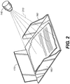
FIG. 2 is a perspective view of a scanner output tray according to the present invention. -
FIG. 3 is a cross-sectional view from the side of a straight through transport of a document scanner according to the present invention. - The present invention will be directed in particular to elements forming part of, or in cooperation more directly with the apparatus in accordance with the present invention. It is to be understood that elements not specifically shown or described may take various forms well known to those skilled in the art.
-
FIG. 1 is a side cross-sectional view of adocument scanner 10. As shown inFIG. 1 ,documents 20 are first placed in theinput tray 30 of thescanner 10. The document is moved forward into thescanner 10 by theurging roller 45, then thefeed roller 50 whileadditional documents 20 are held back by theseparation roller 60. Thedocument 20 continues through thedocument transport 70, is imaged by the front and rearraster capture devices transport exit 130 into theoutput tray 150. - As, or after, the
document 20 exits thetransport 70 at thetransport exit 130, thedocument 20 and theoutput tray 150 are imaged by theoutput imaging device 140. The images are sent to theimage processor 100 to discerndocument 20 andoutput tray 150 characteristics. - One output tray 150 characteristic is whether or not there are
documents 20 present in theoutput tray 150. If theoutput tray 150 is determined to be empty theprocessor 110 will determine howmany documents 20 can be scanned before theoutput tray 150 becomes full. Also determining theoutput tray 150 level of documents will be used by theprocessor 110 to stop scanning if theoutput tray 150 becomes full. This may happen if the operator continues to placedocuments 20 in theinput tray 30 while scanning without removing documents (20) from theoutput tray 150. - Another important characteristic is the stacking of the
documents 20 in theoutput tray 150. If thedocuments 20 are not laying flat, one on top of another, theprocessor 110 will stop the scanning process and preventadditional documents 20 from stacking improperly. Improper stacking may be an indication of the controlled output stacking 120 feature not operating properly or being inadvertently turned off. Based on theoutput tray 150 characteristics, proper adjustment of the outputtray side guides 160 orend stop 170 will be determined. The scanning may be stopped for the operator to adjust theside guides 160 orend stop 170, or an auto adjust feature can be employed to make the correction while scanning is continued. - Based on document information from an
input imaging device 40 the condition of thedocument 20 exiting thescanner 10 will be compared to condition ofdocuments 20 entering thescanner 10 to determine if damage to thedocument 20, such as bent or torn corners, is occurring within thedocument transport 70, as is shown inFIG. 2 . Theprocessor 110 will then stop the scanning process and alert the operator. - Using the information from the
input imaging device 40 the number ofdocuments 20 entering thedocument scanner 10 can be compared to the number ofdocuments 20 exiting thescanner 10. If the number ofdocuments 20 exiting thedocument scanner 10 does not match the number ofdocuments 20 entering thedocument scanner 10 the operator will be alerted to the lostdocument 20. - In a C-
shape document transport 70 thedocument 20 order can be tracked usingdocument 20 content captured by theoutput imaging device 140 in conjunction with the rearraster capture device 90. Indocument scanner 11, shown inFIG. 3 , having a straight throughdocument transport 70, thedocument 20 order can be tracked using thedocument 20 content captured by theoutput imaging device 140 in conjunction with the frontraster capture device 80. - In one embodiment of the invention, an image of a
document 20 in aninput tray 30 is captured with aninput imaging device 40 such as a raster capture device, CCD sensor, or CMOS sensor. The capturedinput tray image 190 is transmitted to animage processor 100 such as a microprocessor or a computer. The document is then transported through adocument scanner 10 which captures a raster scannedimage 180 of thedocument 20 and the raster scannedimage 180 is transmitted to theimage processor 100. Theimage processor 100 verifies the accuracy of the raster scannedimage 180 by comparing the raster scannedimage 180 of thedocument 20 to theinput tray image 190 of thedocument 20. If the raster scannedimage 180 of thedocument 20 does not match theinput tray image 190 of thedocument 20,scanner 10 functions may be modified or other corrective actions taken. Corrective actions may include rotation of the raster capture device, changing a color capture mode, or cleaning image optics. - The
input tray image 190 of thedocument 20 is captured as anarea image 210 rather than raster by raster as is typically used to capture the raster scannedimage 180 of thedocument 20. Theinput tray image 190 of thedocument 20 may be low resolution or high resolution. - In another embodiment of the invention, the
document 20 is moved to anoutput tray 150 for holdingdocuments 20 after it exits thescanner 10 and an image of thedocument 20 in theoutput tray 150 is captured with anoutput imaging device 140. The capturedoutput tray 150 image is transmitted to theimage processor 100 which verifies the accuracy of the raster scannedimage 180 by comparing the raster scannedimage 180 of thedocument 20 to theinput tray image 190 of thedocument 20 and theoutput tray image 200 of thedocument 20. - In yet another embodiment of the invention, an image of a
document 20 in aninput tray 30 for holdingdocuments 20 is captured as anarea image 210 rather than raster by raster with aninput imaging device 40. Capturing the image as anarea image 210 means that an image of theentire document 20 is taken rather than imaging thedocument 20 raster by raster, which is the usual way of scanning adocument 20. The capturedinput tray image 190 is transmitted to animage processor 100 and thedocument 20 is transported to anoutput tray 150. After thefirst document 20 has been transported out of theinput tray 30, an image of asecond document 20 in theinput tray 30 is captured and transmitted to theimage processor 100. - In a further embodiment, an image of the
document 20 in theoutput tray 150 is captured with anoutput imaging device 140 and transmitted to theimage processor 100. The accuracy of theinput tray 30 image is verified by comparing theinput tray image 190 of the document to theoutput tray image 200 of thedocument 20. -
- 10
- document scanner
- 11
- document scanner
- 20
- documents
- 30
- input tray
- 40
- input imaging device
- 45
- urging roller
- 50
- feed roller
- 60
- separation roller
- 70
- document transport
- 80
- front raster capture device
- 90
- rear raster capture device
- 100
- image processor
- 110
- processor
- 120
- controlled output stacking
- 130
- transport exit
- 140
- output imaging device
- 150
- output tray
- 160
- output tray side guides
- 170
- end stop
- 180
- raster scanned image
- 190
- input tray image
- 200
- output tray image
- 210
- area image
Claims (7)
- A system for capturing an image of a document comprising:an input tray (30) for holding documents;an input imaging device (40) that is configured to capture an image of a first document (20) in the input tray (30);wherein the input tray image (190) of the first document (20) is captured as an area image (210) by taking one image of the entire first document (20) with the input imagining device (40);an image processor (100) configured to receive the captured input tray image (190) of the first document (20); anda transport system configured to transport the first document (20) through document scanner (10) to an output tray (150);an output imaging device (140) configured to capture an image of the first document (20) in the output tray (150), and to transmit the captured output tray image (200) of the first document (20) to the image processor (100); a raster capture device (80,90) that captures a raster scanned image (180) of the first document (20); characterized in thatthe image processor (100) is configured to verify the accuracy of the input tray image (190) of the first document (20) by comparing the input tray image (190) of the first document (20) to the output tray image (200) of the first document (20).
- The system as in claim 1 comprising:the input imaging device (40) configured to capture an image of a second document in the input tray (30);wherein the input tray image (190) of the second document is captured as an area image (210) by taking one image of the entire second document with the input imaging device (40);the image processor (100) configured to receive the captured input tray image of the second document to the image processor (100), andto verify the accuracy of the input tray image (190) of the second document by comparing the input tray image (190) of the second document to the output tray image (200) of the second document.
- The system as in claim 2 further configured to modify scanner functions if the raster scanned image (180) of the document does not match the input tray image (190) of the document.
- The system as in claim 3 wherein the scanner functions are selected from a group consisting of rotation of the raster capture device, changing a color capture mode, or cleaning image optics.
- The system as in claim 1 wherein the input tray image (190) of the document is high resolution.
- The system as in claim 2 comprising:
a processor (110) configured to alert a document scanner operator if the raster scanned image (180) of the document does not match the input tray image (190) of the document. - A method of verifying accuracy of a raster scanned image (180) of a document (20) comprising:capturing an input image (90) of the document (20) in an input tray (30) using an input imaging device (40), wherein the input tray image (190) of the document (20) is captured as an area image (210) by taking one image of the entire document (20) with the input imaging device (40);transporting the document (20) through a document scanner (10) to an output tray (150) for holding documents;capturing a raster scanned image (180) of the document (20) using a raster capture device (80, 90);transmitting the raster scanned image (180) to an image processor (100);capturing an image of a document in the output tray (150) using an output imaging device (140);transmitting the captured output tray image (200) to the image processor (100);characterized byverifying the accuracy of the raster scanned image (180) by comparing the raster scanned image (180) of the document (20) to the input tray image (190) of the document (20) and the output tray image (200) of the document (20).
Applications Claiming Priority (2)
| Application Number | Priority Date | Filing Date | Title |
|---|---|---|---|
| US13/714,926 US8879130B2 (en) | 2012-12-14 | 2012-12-14 | System for capturing an image of a document |
| PCT/US2013/075088 WO2014093866A1 (en) | 2012-12-14 | 2013-12-13 | System for capturing an image of a document |
Publications (3)
| Publication Number | Publication Date |
|---|---|
| EP2932701A1 EP2932701A1 (en) | 2015-10-21 |
| EP2932701A4 EP2932701A4 (en) | 2016-08-17 |
| EP2932701B1 true EP2932701B1 (en) | 2021-03-10 |
Family
ID=50930548
Family Applications (1)
| Application Number | Title | Priority Date | Filing Date |
|---|---|---|---|
| EP13863254.2A Active EP2932701B1 (en) | 2012-12-14 | 2013-12-13 | System for capturing an image of a document |
Country Status (5)
| Country | Link |
|---|---|
| US (1) | US8879130B2 (en) |
| EP (1) | EP2932701B1 (en) |
| JP (1) | JP2016507934A (en) |
| CN (1) | CN104854853B (en) |
| WO (1) | WO2014093866A1 (en) |
Family Cites Families (15)
| Publication number | Priority date | Publication date | Assignee | Title |
|---|---|---|---|---|
| US5424804A (en) * | 1994-03-23 | 1995-06-13 | Eastman Kodak Company | Automatic exposure control using density slope control for a planetary microfilmer |
| CN100384210C (en) * | 2001-09-12 | 2008-04-23 | 精工爱普生株式会社 | Composite printer and scanning image duplication method |
| US7742198B2 (en) * | 2001-09-12 | 2010-06-22 | Seiko Epson Corporation | Image processing apparatus and method |
| JP4055385B2 (en) * | 2001-10-11 | 2008-03-05 | 富士ゼロックス株式会社 | Image inspection device |
| JP4423057B2 (en) * | 2004-02-05 | 2010-03-03 | 株式会社 大野印照堂 | Rubber stamp back printing device |
| JP4538845B2 (en) * | 2004-04-21 | 2010-09-08 | 富士ゼロックス株式会社 | FAILURE DIAGNOSIS METHOD, FAILURE DIAGNOSIS DEVICE, IMAGE FORMING DEVICE, PROGRAM, AND STORAGE MEDIUM |
| US7783122B2 (en) | 2006-07-14 | 2010-08-24 | Xerox Corporation | Banding and streak detection using customer documents |
| US20110238423A1 (en) * | 2010-03-29 | 2011-09-29 | Schaertel David M | Sonic document classification |
| US8749801B2 (en) * | 2011-10-13 | 2014-06-10 | Kodak Alaris Inc. | Determining document characteristics prior to scanning |
| US20120019874A1 (en) * | 2010-07-20 | 2012-01-26 | Schaertel David M | Method for document scanning |
| US20120019841A1 (en) * | 2010-07-20 | 2012-01-26 | Schaertel David M | Document scanner |
| US9036222B2 (en) * | 2010-07-20 | 2015-05-19 | Kodak Alaris Inc. | Document scanner |
| US8456718B2 (en) * | 2010-08-18 | 2013-06-04 | Eastman Kodak Company | Document scanner |
| US8472092B2 (en) * | 2010-08-18 | 2013-06-25 | Eastman Kodak Company | Method of scanning documents |
| US9217980B2 (en) * | 2011-10-14 | 2015-12-22 | Kodak Alaris Inc. | Jam sensing at document feeding station |
-
2012
- 2012-12-14 US US13/714,926 patent/US8879130B2/en active Active
-
2013
- 2013-12-13 WO PCT/US2013/075088 patent/WO2014093866A1/en not_active Ceased
- 2013-12-13 JP JP2015548003A patent/JP2016507934A/en active Pending
- 2013-12-13 EP EP13863254.2A patent/EP2932701B1/en active Active
- 2013-12-13 CN CN201380065631.5A patent/CN104854853B/en active Active
Non-Patent Citations (1)
| Title |
|---|
| None * |
Also Published As
| Publication number | Publication date |
|---|---|
| US20140168718A1 (en) | 2014-06-19 |
| JP2016507934A (en) | 2016-03-10 |
| US8879130B2 (en) | 2014-11-04 |
| EP2932701A1 (en) | 2015-10-21 |
| WO2014093866A1 (en) | 2014-06-19 |
| CN104854853B (en) | 2018-07-06 |
| CN104854853A (en) | 2015-08-19 |
| EP2932701A4 (en) | 2016-08-17 |
Similar Documents
| Publication | Publication Date | Title |
|---|---|---|
| EP2606632B1 (en) | A method of scanning documents | |
| US8842346B2 (en) | Document reading device which includes automatic document conveying mechanism and reads plural documents one by one | |
| EP2932702B1 (en) | Method of capturing an image of a document | |
| JP2020178192A (en) | Edge detection device, tilt correction device, reader, image processing device and edge detection method | |
| US20130044339A1 (en) | Image forming apparatus, image forming apparatus control method, and storage medium | |
| US20080316549A1 (en) | Method For Scanning And Processing A Document With An Imaging Apparatus | |
| JP6311641B2 (en) | Image reading apparatus and image forming apparatus | |
| US9264558B2 (en) | System for verifying accuracy of a raster scanned image of a document | |
| JP2013157966A (en) | Image reader | |
| US20090116081A1 (en) | Image Scanning Device and Image Scanning Method | |
| US11290609B2 (en) | Image processing apparatus and image processing method | |
| US8456718B2 (en) | Document scanner | |
| JP2013162343A (en) | Document reading apparatus | |
| EP2767080B1 (en) | Document scanner | |
| US8879130B2 (en) | System for capturing an image of a document | |
| US20100214619A1 (en) | Image processing device and method of processing image | |
| US9363397B2 (en) | Image reading device and image forming apparatus | |
| JP2022012616A (en) | Image reading apparatus | |
| US20240412376A1 (en) | Image processing device, image forming apparatus, and edge detection method | |
| JP4354443B2 (en) | Image reading device | |
| JP2010268319A (en) | Image reader | |
| JP2011063362A (en) | Document carrying device | |
| JP2014175919A (en) | Image reading apparatus, image forming apparatus, and control method and control program of image reading apparatus | |
| JP2010109520A (en) | Image forming device, control method of image forming device, and control program | |
| JP2005045371A (en) | Apparatus and method for reading document |
Legal Events
| Date | Code | Title | Description |
|---|---|---|---|
| PUAI | Public reference made under article 153(3) epc to a published international application that has entered the european phase |
Free format text: ORIGINAL CODE: 0009012 |
|
| 17P | Request for examination filed |
Effective date: 20150714 |
|
| AK | Designated contracting states |
Kind code of ref document: A1 Designated state(s): AL AT BE BG CH CY CZ DE DK EE ES FI FR GB GR HR HU IE IS IT LI LT LU LV MC MK MT NL NO PL PT RO RS SE SI SK SM TR |
|
| AX | Request for extension of the european patent |
Extension state: BA ME |
|
| DAX | Request for extension of the european patent (deleted) | ||
| REG | Reference to a national code |
Ref country code: DE Ref legal event code: R079 Ref document number: 602013076227 Country of ref document: DE Free format text: PREVIOUS MAIN CLASS: H04N0001040000 Ipc: H04N0001320000 |
|
| A4 | Supplementary search report drawn up and despatched |
Effective date: 20160715 |
|
| RIC1 | Information provided on ipc code assigned before grant |
Ipc: H04N 1/32 20060101AFI20160712BHEP Ipc: H04N 1/00 20060101ALI20160712BHEP |
|
| STAA | Information on the status of an ep patent application or granted ep patent |
Free format text: STATUS: EXAMINATION IS IN PROGRESS |
|
| 17Q | First examination report despatched |
Effective date: 20190322 |
|
| GRAP | Despatch of communication of intention to grant a patent |
Free format text: ORIGINAL CODE: EPIDOSNIGR1 |
|
| STAA | Information on the status of an ep patent application or granted ep patent |
Free format text: STATUS: GRANT OF PATENT IS INTENDED |
|
| INTG | Intention to grant announced |
Effective date: 20201007 |
|
| GRAS | Grant fee paid |
Free format text: ORIGINAL CODE: EPIDOSNIGR3 |
|
| GRAA | (expected) grant |
Free format text: ORIGINAL CODE: 0009210 |
|
| STAA | Information on the status of an ep patent application or granted ep patent |
Free format text: STATUS: THE PATENT HAS BEEN GRANTED |
|
| AK | Designated contracting states |
Kind code of ref document: B1 Designated state(s): AL AT BE BG CH CY CZ DE DK EE ES FI FR GB GR HR HU IE IS IT LI LT LU LV MC MK MT NL NO PL PT RO RS SE SI SK SM TR |
|
| REG | Reference to a national code |
Ref country code: GB Ref legal event code: FG4D |
|
| REG | Reference to a national code |
Ref country code: CH Ref legal event code: EP Ref country code: AT Ref legal event code: REF Ref document number: 1371130 Country of ref document: AT Kind code of ref document: T Effective date: 20210315 |
|
| REG | Reference to a national code |
Ref country code: DE Ref legal event code: R096 Ref document number: 602013076227 Country of ref document: DE |
|
| REG | Reference to a national code |
Ref country code: IE Ref legal event code: FG4D |
|
| REG | Reference to a national code |
Ref country code: NL Ref legal event code: FP |
|
| REG | Reference to a national code |
Ref country code: LT Ref legal event code: MG9D |
|
| PG25 | Lapsed in a contracting state [announced via postgrant information from national office to epo] |
Ref country code: HR Free format text: LAPSE BECAUSE OF FAILURE TO SUBMIT A TRANSLATION OF THE DESCRIPTION OR TO PAY THE FEE WITHIN THE PRESCRIBED TIME-LIMIT Effective date: 20210310 Ref country code: FI Free format text: LAPSE BECAUSE OF FAILURE TO SUBMIT A TRANSLATION OF THE DESCRIPTION OR TO PAY THE FEE WITHIN THE PRESCRIBED TIME-LIMIT Effective date: 20210310 Ref country code: GR Free format text: LAPSE BECAUSE OF FAILURE TO SUBMIT A TRANSLATION OF THE DESCRIPTION OR TO PAY THE FEE WITHIN THE PRESCRIBED TIME-LIMIT Effective date: 20210611 Ref country code: LT Free format text: LAPSE BECAUSE OF FAILURE TO SUBMIT A TRANSLATION OF THE DESCRIPTION OR TO PAY THE FEE WITHIN THE PRESCRIBED TIME-LIMIT Effective date: 20210310 Ref country code: NO Free format text: LAPSE BECAUSE OF FAILURE TO SUBMIT A TRANSLATION OF THE DESCRIPTION OR TO PAY THE FEE WITHIN THE PRESCRIBED TIME-LIMIT Effective date: 20210610 Ref country code: BG Free format text: LAPSE BECAUSE OF FAILURE TO SUBMIT A TRANSLATION OF THE DESCRIPTION OR TO PAY THE FEE WITHIN THE PRESCRIBED TIME-LIMIT Effective date: 20210610 |
|
| REG | Reference to a national code |
Ref country code: AT Ref legal event code: MK05 Ref document number: 1371130 Country of ref document: AT Kind code of ref document: T Effective date: 20210310 |
|
| PG25 | Lapsed in a contracting state [announced via postgrant information from national office to epo] |
Ref country code: SE Free format text: LAPSE BECAUSE OF FAILURE TO SUBMIT A TRANSLATION OF THE DESCRIPTION OR TO PAY THE FEE WITHIN THE PRESCRIBED TIME-LIMIT Effective date: 20210310 Ref country code: RS Free format text: LAPSE BECAUSE OF FAILURE TO SUBMIT A TRANSLATION OF THE DESCRIPTION OR TO PAY THE FEE WITHIN THE PRESCRIBED TIME-LIMIT Effective date: 20210310 Ref country code: LV Free format text: LAPSE BECAUSE OF FAILURE TO SUBMIT A TRANSLATION OF THE DESCRIPTION OR TO PAY THE FEE WITHIN THE PRESCRIBED TIME-LIMIT Effective date: 20210310 |
|
| PG25 | Lapsed in a contracting state [announced via postgrant information from national office to epo] |
Ref country code: EE Free format text: LAPSE BECAUSE OF FAILURE TO SUBMIT A TRANSLATION OF THE DESCRIPTION OR TO PAY THE FEE WITHIN THE PRESCRIBED TIME-LIMIT Effective date: 20210310 Ref country code: CZ Free format text: LAPSE BECAUSE OF FAILURE TO SUBMIT A TRANSLATION OF THE DESCRIPTION OR TO PAY THE FEE WITHIN THE PRESCRIBED TIME-LIMIT Effective date: 20210310 Ref country code: AT Free format text: LAPSE BECAUSE OF FAILURE TO SUBMIT A TRANSLATION OF THE DESCRIPTION OR TO PAY THE FEE WITHIN THE PRESCRIBED TIME-LIMIT Effective date: 20210310 Ref country code: SM Free format text: LAPSE BECAUSE OF FAILURE TO SUBMIT A TRANSLATION OF THE DESCRIPTION OR TO PAY THE FEE WITHIN THE PRESCRIBED TIME-LIMIT Effective date: 20210310 |
|
| PG25 | Lapsed in a contracting state [announced via postgrant information from national office to epo] |
Ref country code: ES Free format text: LAPSE BECAUSE OF FAILURE TO SUBMIT A TRANSLATION OF THE DESCRIPTION OR TO PAY THE FEE WITHIN THE PRESCRIBED TIME-LIMIT Effective date: 20210310 Ref country code: PT Free format text: LAPSE BECAUSE OF FAILURE TO SUBMIT A TRANSLATION OF THE DESCRIPTION OR TO PAY THE FEE WITHIN THE PRESCRIBED TIME-LIMIT Effective date: 20210712 Ref country code: PL Free format text: LAPSE BECAUSE OF FAILURE TO SUBMIT A TRANSLATION OF THE DESCRIPTION OR TO PAY THE FEE WITHIN THE PRESCRIBED TIME-LIMIT Effective date: 20210310 Ref country code: SK Free format text: LAPSE BECAUSE OF FAILURE TO SUBMIT A TRANSLATION OF THE DESCRIPTION OR TO PAY THE FEE WITHIN THE PRESCRIBED TIME-LIMIT Effective date: 20210310 Ref country code: RO Free format text: LAPSE BECAUSE OF FAILURE TO SUBMIT A TRANSLATION OF THE DESCRIPTION OR TO PAY THE FEE WITHIN THE PRESCRIBED TIME-LIMIT Effective date: 20210310 Ref country code: IS Free format text: LAPSE BECAUSE OF FAILURE TO SUBMIT A TRANSLATION OF THE DESCRIPTION OR TO PAY THE FEE WITHIN THE PRESCRIBED TIME-LIMIT Effective date: 20210710 |
|
| REG | Reference to a national code |
Ref country code: DE Ref legal event code: R097 Ref document number: 602013076227 Country of ref document: DE |
|
| PLBE | No opposition filed within time limit |
Free format text: ORIGINAL CODE: 0009261 |
|
| STAA | Information on the status of an ep patent application or granted ep patent |
Free format text: STATUS: NO OPPOSITION FILED WITHIN TIME LIMIT |
|
| PG25 | Lapsed in a contracting state [announced via postgrant information from national office to epo] |
Ref country code: DK Free format text: LAPSE BECAUSE OF FAILURE TO SUBMIT A TRANSLATION OF THE DESCRIPTION OR TO PAY THE FEE WITHIN THE PRESCRIBED TIME-LIMIT Effective date: 20210310 Ref country code: AL Free format text: LAPSE BECAUSE OF FAILURE TO SUBMIT A TRANSLATION OF THE DESCRIPTION OR TO PAY THE FEE WITHIN THE PRESCRIBED TIME-LIMIT Effective date: 20210310 |
|
| 26N | No opposition filed |
Effective date: 20211213 |
|
| PG25 | Lapsed in a contracting state [announced via postgrant information from national office to epo] |
Ref country code: SI Free format text: LAPSE BECAUSE OF FAILURE TO SUBMIT A TRANSLATION OF THE DESCRIPTION OR TO PAY THE FEE WITHIN THE PRESCRIBED TIME-LIMIT Effective date: 20210310 |
|
| PG25 | Lapsed in a contracting state [announced via postgrant information from national office to epo] |
Ref country code: IT Free format text: LAPSE BECAUSE OF FAILURE TO SUBMIT A TRANSLATION OF THE DESCRIPTION OR TO PAY THE FEE WITHIN THE PRESCRIBED TIME-LIMIT Effective date: 20210310 |
|
| PG25 | Lapsed in a contracting state [announced via postgrant information from national office to epo] |
Ref country code: IS Free format text: LAPSE BECAUSE OF FAILURE TO SUBMIT A TRANSLATION OF THE DESCRIPTION OR TO PAY THE FEE WITHIN THE PRESCRIBED TIME-LIMIT Effective date: 20210710 |
|
| PG25 | Lapsed in a contracting state [announced via postgrant information from national office to epo] |
Ref country code: MC Free format text: LAPSE BECAUSE OF FAILURE TO SUBMIT A TRANSLATION OF THE DESCRIPTION OR TO PAY THE FEE WITHIN THE PRESCRIBED TIME-LIMIT Effective date: 20210310 |
|
| REG | Reference to a national code |
Ref country code: CH Ref legal event code: PL |
|
| REG | Reference to a national code |
Ref country code: BE Ref legal event code: MM Effective date: 20211231 |
|
| PG25 | Lapsed in a contracting state [announced via postgrant information from national office to epo] |
Ref country code: LU Free format text: LAPSE BECAUSE OF NON-PAYMENT OF DUE FEES Effective date: 20211213 Ref country code: IE Free format text: LAPSE BECAUSE OF NON-PAYMENT OF DUE FEES Effective date: 20211213 |
|
| PG25 | Lapsed in a contracting state [announced via postgrant information from national office to epo] |
Ref country code: FR Free format text: LAPSE BECAUSE OF NON-PAYMENT OF DUE FEES Effective date: 20211231 Ref country code: BE Free format text: LAPSE BECAUSE OF NON-PAYMENT OF DUE FEES Effective date: 20211231 |
|
| PG25 | Lapsed in a contracting state [announced via postgrant information from national office to epo] |
Ref country code: LI Free format text: LAPSE BECAUSE OF NON-PAYMENT OF DUE FEES Effective date: 20211231 Ref country code: CH Free format text: LAPSE BECAUSE OF NON-PAYMENT OF DUE FEES Effective date: 20211231 |
|
| PG25 | Lapsed in a contracting state [announced via postgrant information from national office to epo] |
Ref country code: HU Free format text: LAPSE BECAUSE OF FAILURE TO SUBMIT A TRANSLATION OF THE DESCRIPTION OR TO PAY THE FEE WITHIN THE PRESCRIBED TIME-LIMIT; INVALID AB INITIO Effective date: 20131213 |
|
| PG25 | Lapsed in a contracting state [announced via postgrant information from national office to epo] |
Ref country code: CY Free format text: LAPSE BECAUSE OF FAILURE TO SUBMIT A TRANSLATION OF THE DESCRIPTION OR TO PAY THE FEE WITHIN THE PRESCRIBED TIME-LIMIT Effective date: 20210310 |
|
| PG25 | Lapsed in a contracting state [announced via postgrant information from national office to epo] |
Ref country code: MK Free format text: LAPSE BECAUSE OF FAILURE TO SUBMIT A TRANSLATION OF THE DESCRIPTION OR TO PAY THE FEE WITHIN THE PRESCRIBED TIME-LIMIT Effective date: 20210310 |
|
| PG25 | Lapsed in a contracting state [announced via postgrant information from national office to epo] |
Ref country code: TR Free format text: LAPSE BECAUSE OF FAILURE TO SUBMIT A TRANSLATION OF THE DESCRIPTION OR TO PAY THE FEE WITHIN THE PRESCRIBED TIME-LIMIT Effective date: 20210310 |
|
| PG25 | Lapsed in a contracting state [announced via postgrant information from national office to epo] |
Ref country code: MT Free format text: LAPSE BECAUSE OF FAILURE TO SUBMIT A TRANSLATION OF THE DESCRIPTION OR TO PAY THE FEE WITHIN THE PRESCRIBED TIME-LIMIT Effective date: 20210310 |
|
| PGFP | Annual fee paid to national office [announced via postgrant information from national office to epo] |
Ref country code: NL Payment date: 20241114 Year of fee payment: 12 |
|
| PGFP | Annual fee paid to national office [announced via postgrant information from national office to epo] |
Ref country code: DE Payment date: 20241111 Year of fee payment: 12 |
|
| PGFP | Annual fee paid to national office [announced via postgrant information from national office to epo] |
Ref country code: GB Payment date: 20241114 Year of fee payment: 12 |
|
| REG | Reference to a national code |
Ref country code: GB Ref legal event code: 732E Free format text: REGISTERED BETWEEN 20250925 AND 20251001 |
|
| REG | Reference to a national code |
Ref country code: NL Ref legal event code: MM Effective date: 20260101 |