EP2932240B1 - Optical sensor for oil saturation - Google Patents
Optical sensor for oil saturation Download PDFInfo
- Publication number
- EP2932240B1 EP2932240B1 EP12809707.8A EP12809707A EP2932240B1 EP 2932240 B1 EP2932240 B1 EP 2932240B1 EP 12809707 A EP12809707 A EP 12809707A EP 2932240 B1 EP2932240 B1 EP 2932240B1
- Authority
- EP
- European Patent Office
- Prior art keywords
- oil
- light
- saturation
- light signal
- fluctuation
- Prior art date
- Legal status (The legal status is an assumption and is not a legal conclusion. Google has not performed a legal analysis and makes no representation as to the accuracy of the status listed.)
- Not-in-force
Links
Images

Classifications
-
- G—PHYSICS
- G01—MEASURING; TESTING
- G01N—INVESTIGATING OR ANALYSING MATERIALS BY DETERMINING THEIR CHEMICAL OR PHYSICAL PROPERTIES
- G01N33/00—Investigating or analysing materials by specific methods not covered by groups G01N1/00 - G01N31/00
- G01N33/26—Oils; Viscous liquids; Paints; Inks
- G01N33/28—Oils, i.e. hydrocarbon liquids
- G01N33/2835—Specific substances contained in the oils or fuels
- G01N33/2847—Water in oils
-
- G—PHYSICS
- G01—MEASURING; TESTING
- G01N—INVESTIGATING OR ANALYSING MATERIALS BY DETERMINING THEIR CHEMICAL OR PHYSICAL PROPERTIES
- G01N21/00—Investigating or analysing materials by the use of optical means, i.e. using sub-millimetre waves, infrared, visible or ultraviolet light
- G01N21/17—Systems in which incident light is modified in accordance with the properties of the material investigated
- G01N21/59—Transmissivity
-
- G—PHYSICS
- G01—MEASURING; TESTING
- G01N—INVESTIGATING OR ANALYSING MATERIALS BY DETERMINING THEIR CHEMICAL OR PHYSICAL PROPERTIES
- G01N21/00—Investigating or analysing materials by the use of optical means, i.e. using sub-millimetre waves, infrared, visible or ultraviolet light
- G01N21/84—Systems specially adapted for particular applications
- G01N21/85—Investigating moving fluids or granular solids
- G01N21/8507—Probe photometers, i.e. with optical measuring part dipped into fluid sample
-
- G—PHYSICS
- G01—MEASURING; TESTING
- G01N—INVESTIGATING OR ANALYSING MATERIALS BY DETERMINING THEIR CHEMICAL OR PHYSICAL PROPERTIES
- G01N33/00—Investigating or analysing materials by specific methods not covered by groups G01N1/00 - G01N31/00
- G01N33/26—Oils; Viscous liquids; Paints; Inks
- G01N33/28—Oils, i.e. hydrocarbon liquids
- G01N33/2888—Lubricating oil characteristics, e.g. deterioration
Definitions
- the present invention relates to oil condition monitoring and in particular, to a sensor for detecting the saturation level of water in oil or like substances.
- the invention also relates to a method of monitoring the presence of water in oil and in particular to a method which allows easy auto-calibration of the sensor in-situ.
- Optical sensors have been used for oil condition monitoring for determining the presence of debris or otherwise monitor deterioration of a lubricant. Such devices may operate by shining light through a small gap and analysing the transmitted light with a suitable optical sensor. Alternative sensors may make use of scattering of light and may operate over different frequencies including outside of the visible range. Oil condition monitoring may be significant in providing feedback in advance of likely failure of a lubricant system. Action may be taken to perform maintenance or otherwise renew the lubricant.
- Water in oil is of considerable concern to many mechanical systems. Minimal amounts of water may be absorbed by the oil during use, either from the atmosphere or by direct ingress of water into the system. As long as this water is in the absorbed state and the oil is unsaturated, the concern is minimal. Nevertheless, as the concentration of water approaches the saturation level, emulsified and free water may occur, which can be highly detrimental, especially if exposure is prolonged. In bearings, the incompressibility of water relative to the oil can result in disruption of the oil film leading to excessive wear. Just one percent water in oil can reduce the life expectancy of a bearing by as much as 90 percent. For ball or rolling element bearings, the localized pressure generated can cause spontaneous vaporization of the water, leading to erosive wear such as micropitting.
- the saturation level of water in oil may vary widely according to temperature and the type of oil and can range from 10 ppm to even 10000 ppm.
- Existing sensors capable of measuring the presence of water (free and dissolved) include capacitive sensors and Karl Fischer titration sensors. Both of these methods require considerable time for the sensor to reach equilibrium and are not ideal for rapidly changing conditions.
- Spectral analysis using Fourier Transform Infrared Spectroscopy (FTIR) has been used but is a relatively complex and costly procedure requiring calibration of the sensor relative to the spectrum produced with fresh oil.
- a method of in-situ detecting the saturation level of water in oil in a mechanical system comprising: providing an optical sensor having a gap for transmission of light between an emitter and receiver through a sample of the oil; passing light through the oil from the emitter to the receiver; detecting at the receiver, the light transmitted from the emitter and producing a light signal representative of the light intensity detected; analysing the light signal to determine an amount of fluctuation of the light intensity in time; monitoring the amount of fluctuation of the light signal to identify a step change attributable to the formation of bubbles of free water and generating a saturation signal indicative of saturation if the identified step change exceeds a predetermined value representing saturation of the oil.
- the amount of fluctuation may be determined by measuring a maximum peak to peak variation of the light signal within a sampling period.
- the sampling period may be chosen depending on various factors, including the sampling rate at which measurements of the light signal are taken and also based on physical factors such as the flow rate of the oil being monitored. It will be understood that the sampling period will include at least two samples, preferably at least four samples and more preferably at least 10 samples.
- the sampling period is between 1 second and 10 seconds, preferably between 2 second and 5 seconds.
- a sample rate of between 1 Hz and 10 Hz may be used, preferably around 2Hz, again depending on the flow rate. In general, for a higher flow rate of the oil, a higher sample rate may be required for the same sensitivity.
- saturation may be identified when a ratio of the light signal fluctuation in a second sampling period to the light signal fluctuation in a first sampling period exceeds a predetermined value.
- the predetermined value may be determined according to the nature of the oil and other physical factors. In general, with the onset of free water the signal fluctuation may increase ten-fold or more and a predetermined value of 5 may be sufficient to provide reliable indication while avoiding false alarms. In other circumstances, a predetermined value of 2 may provide more sensitive response and predetermined values of below 2 may be applicable, in particular where signal smoothing has previously been applied.
- the method may further comprise determining the time that the oil remains above its saturation level. Once free water is detected in the oil, a timer may register the time elapsed until the danger of free water has receded. This point may be determined by evaluating a number of successive sampling periods and determining that water is absent once absence of saturation signal has been determined for all of these periods. Alternatively, once the absolute value of the light signal corresponding to the saturation level has been determined, the absence of free water may be indicated once the absolute value of the light signal returns to a value distant from the saturation level.
- the exposure of the system to free water may be determined by integrating the saturation signal with respect to time. Based on the flow rate of the oil through the sensor, integration of the signal may allow an approximate determination of the total amount of free water in the system. This may be used to provide further alarms and initiate appropriate actions in the event that a given exposure is exceeded.
- the method is particularly effective for infra red light in the range from 850 nm to 1750 nm.
- Near infra red light shows good absorption properties for water while being only slightly affected by other contaminants in the oil.
- the light may be analysed over a broad spectrum e.g. using a spectroanalysisr. Most preferably, the light is analysed in regions of the spectrum where water absorption peaks are present. For most oils, such absorption peaks may be identified at around 1250 nm and around 1400 nm and analysis in one or both of these specific regions is preferred.
- the method may comprise calibrating the sensor for a sample of oil having a water content below the saturation level and subsequently determining a linear relation between the light signal and the water content when saturation of the oil is detected.
- calibrating the sensor may be achieved in a laboratory by calibrating the sensor against a Karl Fischer titration result.
- the sensor may be calibrated in the field by taking an oil sample for off-line analysis. Once calibrated, the sensor may be accurately used to also identify emulsified water in oil before the advent of free water.
- the invention also relates to a system for detecting the saturation level of water in oil, the system comprising: an optical sensor having an emitter and a receiver, separated by a gap for transmission of light therebetween through a sample of the oil, the receiver being arranged to detect light transmitted through the oil from the emitter and produce a light signal representative of the light intensity detected; a processor arranged to analyse the light signal produced by the receiver and determine an amount of fluctuation of the light signal in time; and a memory for storing data relating to a preset value for an expected fluctuation of the light signal attributable to the formation of bubbles of free water and indicative of full saturation of the oil.
- the system may be implemented to operate according to the method as described above.
- the optical sensor may have a gap of less than 2 mm, preferably less than 1 mm and most preferably around 0.5 mm. It has been found that increase light sensitivity may be achieved with a smaller gap. Nevertheless, a gap of around 0.5 mm is considered optimal, as it allows more than sufficient light transmission for most oils and is not so narrow that clogging with debris could occur. It will be understood that for relatively more viscous oils a larger gap might be considered than for lighter oils.
- the emitter comprises a broad spectrum lamp and the receiver comprises a spectroanalyser capable of analysing the light signal across the range, preferably at least across the relevant wavelengths as discussed above.
- the emitter comprises one or more light emitting diodes (LEDs) and the receiver comprises one or more photodiodes, operating at the corresponding frequency.
- the LEDs may thus be coupled to a respective photodiode across the gap.
- the processor may be any appropriate processing device such as a computer or dedicated microprocessor.
- the processor is arranged to determine when the fluctuation of the light signal exceeds the preset value.
- the processor may carry out signal analysis, sampling and filtering as described above.
- the senor of the present invention may be implemented in a number of different situations where water in oil is to be recorded.
- the optical sensor is located in an oil supply line to a mechanical system.
- the mechanical system may be a motor, a gear, a bearing, a journal, a cam or a complex system comprising one or more of the above.
- Figure 1 shows a schematic view of an experimental set up of a system 10 according to the present invention, comprising a deuterium/halogen lamp source 12 coupled to an optical fibre emitter 14.
- the optical fibre emitter 14 is coupled to a detection cell 16 comprising a gap 18. Facing the optical fibre emitter 14 across the gap 18 is an optical fibre receiver 20 coupled to a spectroanalysisr 22.
- the spectroanalysisr 22 is in turn connected to a personal computer 24.
- Both the optical fibre emitter 14 and optical fibre receiver 20 comprised optical fibres of 400 mm length.
- a stirrer 26 is provided to circulate the oil 28 contained in beaker 30.
- the detection cell 16 is immersed in the oil 28 or other lubricant to be monitored.
- the location of the cell 16 in the lubricant system will depend on the specific situation but it may preferably be provided in a delivery line, leading from a sump to the mechanism to be lubricated.
- Example 2 In a subsequent test, the same system 10 was used as in Example 1, whereby the 0.5 mm gap detection cell 16 was employed. The full spectrum was recorded over a number of hours, during which the concentration of the water was steadily increased until the saturation level was reached (100% saturated). After this the water concentration was further increased to about 0.4% water. The light intensity measurements for the full experimental test are shown in Figure 3 for the wavelength of 1108 nm. The result shows a strong and stable response to the ever increasing levels of water content. As the sample reaches saturation, the sensor records significant fluctuation in the signal. The sampling rate was 2 Hz. The skilled person will recognize that digital filtering such as a moving point average could be used to further smooth the signal.
- digital filtering such as a moving point average could be used to further smooth the signal.
- Example 2 The measurements as performed in Example 2 were repeated in a controlled climate chamber. By adjusting the humidity steadily, it could be assumed that the oil would be in equilibrium with the air in the chamber and have the same relative humidity.
- the measurements were performed in parallel with commercial (Hydac and Pal) capacitance sensors which absorb or desorb moisture, to achieve equilibrium with the surrounding fluid.
- the results are displayed in Figure 4 in which the relative humidity value is based on the reading for the controlled climate within the chamber. After 3 hours of recording, the Hydac and Pal sensors did not show significant variation of the saturation measured values (30% and respectively 35%), while the detection cell 16 indicated 70% saturation. At this point, visual observation of the oil showed that it had changed from very transparent to non-transparent.
- the atmospheric humidity of the chamber was 100% humidity.
- the detection cell 10 registered absolute humidity of 100%.
- the Pal and Hydac sensors registered within the 50-70% range respectively.
- the results as plotted in Figure 4 appear to show a delay of 1 to 3 hours for these sensors with respect to the actual values. It is also noted that beyond saturation in the free water region, the detection cell 16 continues to show variation and allows calibration and measurement in this region.
- the Pal and Hydac sensors reach a plateau at saturation and do not register the free water content.
- the detection cell may be located in an oil supply line whereby a portion of the oil supply passes through the gap.
- the personal computer may be replaced by a dedicated microprocessor which may be located in-situ or remotely. Accordingly, although specific embodiments have been described, these are examples only and are not limiting upon the scope of the invention.
Landscapes
- Chemical & Material Sciences (AREA)
- Health & Medical Sciences (AREA)
- Life Sciences & Earth Sciences (AREA)
- Immunology (AREA)
- Analytical Chemistry (AREA)
- Biochemistry (AREA)
- General Health & Medical Sciences (AREA)
- General Physics & Mathematics (AREA)
- Physics & Mathematics (AREA)
- Pathology (AREA)
- Engineering & Computer Science (AREA)
- Chemical Kinetics & Catalysis (AREA)
- General Chemical & Material Sciences (AREA)
- Oil, Petroleum & Natural Gas (AREA)
- Food Science & Technology (AREA)
- Medicinal Chemistry (AREA)
- Investigating Or Analysing Materials By Optical Means (AREA)
Description
- The present invention relates to oil condition monitoring and in particular, to a sensor for detecting the saturation level of water in oil or like substances. The invention also relates to a method of monitoring the presence of water in oil and in particular to a method which allows easy auto-calibration of the sensor in-situ.
- Optical sensors have been used for oil condition monitoring for determining the presence of debris or otherwise monitor deterioration of a lubricant. Such devices may operate by shining light through a small gap and analysing the transmitted light with a suitable optical sensor. Alternative sensors may make use of scattering of light and may operate over different frequencies including outside of the visible range. Oil condition monitoring may be significant in providing feedback in advance of likely failure of a lubricant system. Action may be taken to perform maintenance or otherwise renew the lubricant.
- Water in oil is of considerable concern to many mechanical systems. Minimal amounts of water may be absorbed by the oil during use, either from the atmosphere or by direct ingress of water into the system. As long as this water is in the absorbed state and the oil is unsaturated, the concern is minimal. Nevertheless, as the concentration of water approaches the saturation level, emulsified and free water may occur, which can be highly detrimental, especially if exposure is prolonged. In bearings, the incompressibility of water relative to the oil can result in disruption of the oil film leading to excessive wear. Just one percent water in oil can reduce the life expectancy of a bearing by as much as 90 percent. For ball or rolling element bearings, the localized pressure generated can cause spontaneous vaporization of the water, leading to erosive wear such as micropitting. The saturation level of water in oil may vary widely according to temperature and the type of oil and can range from 10 ppm to even 10000 ppm. Existing sensors capable of measuring the presence of water (free and dissolved) include capacitive sensors and Karl Fischer titration sensors. Both of these methods require considerable time for the sensor to reach equilibrium and are not ideal for rapidly changing conditions. Spectral analysis using Fourier Transform Infrared Spectroscopy (FTIR) has been used but is a relatively complex and costly procedure requiring calibration of the sensor relative to the spectrum produced with fresh oil.
- According to the invention there is provided a method of in-situ detecting the saturation level of water in oil in a mechanical system, comprising: providing an optical sensor having a gap for transmission of light between an emitter and receiver through a sample of the oil; passing light through the oil from the emitter to the receiver; detecting at the receiver, the light transmitted from the emitter and producing a light signal representative of the light intensity detected; analysing the light signal to determine an amount of fluctuation of the light intensity in time; monitoring the amount of fluctuation of the light signal to identify a step change attributable to the formation of bubbles of free water and generating a saturation signal indicative of saturation if the identified step change exceeds a predetermined value representing saturation of the oil. According to the invention, it has been observed that a significant change in signal characteristic is to be observed at the point at which free water appears in the oil. Below the saturation level, the light signal as received by the receiver is relatively stable and only steadily decreases in intensity with increasing absorbed water content. As the amount of water approaches saturation, the light signal becomes highly unstable and may appear noisy. Without wishing to be bound by theory, it is believed that bubbles of free water are formed within the oil in a manner similar to cavitation or boiling of a liquid. As these bubbles pass the sensor, they disturb the signal, effectively leading to greater absorption of the light and a lower light signal. A significant advantage of the above effect is that a sensor can be easily calibrated in-situ to the saturation level, without requiring knowledge of either the oil or sensor characteristics. Additionally, the sensor can provide real-time results with negligible delay in identifying the presence of free water in the oil.
- Determination of the onset of free water and the step change in fluctuation of the signal can be realised in many ways as will be evident to the skilled person. This may be determined visually and manually on reviewing a data stream record of the light signal. Alternatively and preferably, the method may be carried out by a signal processor using an appropriate algorithm. In one embodiment of the invention, the amount of fluctuation may be determined by measuring a maximum peak to peak variation of the light signal within a sampling period. The sampling period may be chosen depending on various factors, including the sampling rate at which measurements of the light signal are taken and also based on physical factors such as the flow rate of the oil being monitored. It will be understood that the sampling period will include at least two samples, preferably at least four samples and more preferably at least 10 samples.
- In a preferred method, the sampling period is between 1 second and 10 seconds, preferably between 2 second and 5 seconds. A sample rate of between 1 Hz and 10 Hz may be used, preferably around 2Hz, again depending on the flow rate. In general, for a higher flow rate of the oil, a higher sample rate may be required for the same sensitivity.
- According to one method of analysis, saturation may be identified when a ratio of the light signal fluctuation in a second sampling period to the light signal fluctuation in a first sampling period exceeds a predetermined value. The predetermined value may be determined according to the nature of the oil and other physical factors. In general, with the onset of free water the signal fluctuation may increase ten-fold or more and a predetermined value of 5 may be sufficient to provide reliable indication while avoiding false alarms. In other circumstances, a predetermined value of 2 may provide more sensitive response and predetermined values of below 2 may be applicable, in particular where signal smoothing has previously been applied.
- According to a further aspect of the invention, the method may further comprise determining the time that the oil remains above its saturation level. Once free water is detected in the oil, a timer may register the time elapsed until the danger of free water has receded. This point may be determined by evaluating a number of successive sampling periods and determining that water is absent once absence of saturation signal has been determined for all of these periods. Alternatively, once the absolute value of the light signal corresponding to the saturation level has been determined, the absence of free water may be indicated once the absolute value of the light signal returns to a value distant from the saturation level.
- According to an alternative method, the exposure of the system to free water may be determined by integrating the saturation signal with respect to time. Based on the flow rate of the oil through the sensor, integration of the signal may allow an approximate determination of the total amount of free water in the system. This may be used to provide further alarms and initiate appropriate actions in the event that a given exposure is exceeded.
- According to the invention, it has been found that the method is particularly effective for infra red light in the range from 850 nm to 1750 nm. Near infra red light shows good absorption properties for water while being only slightly affected by other contaminants in the oil. The light may be analysed over a broad spectrum e.g. using a spectroanalyser. Most preferably, the light is analysed in regions of the spectrum where water absorption peaks are present. For most oils, such absorption peaks may be identified at around 1250 nm and around 1400 nm and analysis in one or both of these specific regions is preferred.
- As described, a significant advantage of the present invention is that the sensor need not be pre-calibrated and may be calibrated in-situ to the saturation level. In the event that greater accuracy is required in the region of absorbed water, the method may comprise calibrating the sensor for a sample of oil having a water content below the saturation level and subsequently determining a linear relation between the light signal and the water content when saturation of the oil is detected. Such a simple calibration may be achieved in a laboratory by calibrating the sensor against a Karl Fischer titration result. Alternatively, the sensor may be calibrated in the field by taking an oil sample for off-line analysis. Once calibrated, the sensor may be accurately used to also identify emulsified water in oil before the advent of free water.
- The invention also relates to a system for detecting the saturation level of water in oil, the system comprising: an optical sensor having an emitter and a receiver, separated by a gap for transmission of light therebetween through a sample of the oil, the receiver being arranged to detect light transmitted through the oil from the emitter and produce a light signal representative of the light intensity detected; a processor arranged to analyse the light signal produced by the receiver and determine an amount of fluctuation of the light signal in time; and a memory for storing data relating to a preset value for an expected fluctuation of the light signal attributable to the formation of bubbles of free water and indicative of full saturation of the oil. The system may be implemented to operate according to the method as described above.
- According to the invention, the optical sensor may have a gap of less than 2 mm, preferably less than 1 mm and most preferably around 0.5 mm. It has been found that increase light sensitivity may be achieved with a smaller gap. Nevertheless, a gap of around 0.5 mm is considered optimal, as it allows more than sufficient light transmission for most oils and is not so narrow that clogging with debris could occur. It will be understood that for relatively more viscous oils a larger gap might be considered than for lighter oils.
- In one embodiment, the emitter comprises a broad spectrum lamp and the receiver comprises a spectroanalyser capable of analysing the light signal across the range, preferably at least across the relevant wavelengths as discussed above.
- In an alternative embodiment, the emitter comprises one or more light emitting diodes (LEDs) and the receiver comprises one or more photodiodes, operating at the corresponding frequency. The LEDs may thus be coupled to a respective photodiode across the gap.
- The processor may be any appropriate processing device such as a computer or dedicated microprocessor. In addition to other control tasks, the processor is arranged to determine when the fluctuation of the light signal exceeds the preset value. In particular the processor may carry out signal analysis, sampling and filtering as described above.
- The skilled person will understand that the sensor of the present invention may be implemented in a number of different situations where water in oil is to be recorded. Preferably, the optical sensor is located in an oil supply line to a mechanical system. The mechanical system may be a motor, a gear, a bearing, a journal, a cam or a complex system comprising one or more of the above.
- The features and advantages of the invention will be appreciated upon reference to the following drawings of a number of exemplary embodiments, in which:
-
Figure 1 shows a schematic view of a system according to the present invention; -
Figure 2 shows a graph of light intensity signal detected by the system ofFigure 1 over the range of wavelengths from 850nm to 1700 nm; -
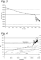
Figure 3 shows light intensity measurements for increasing water content measured in the system ofFigure 1 for the wavelength of 1108 nm; and -
Figure 4 shows relative humidity measurements for the system ofFigure 1 in parallel with commercial sensors. -
Figure 1 shows a schematic view of an experimental set up of asystem 10 according to the present invention, comprising a deuterium/halogen lamp source 12 coupled to anoptical fibre emitter 14. Theoptical fibre emitter 14 is coupled to adetection cell 16 comprising agap 18. Facing theoptical fibre emitter 14 across thegap 18 is anoptical fibre receiver 20 coupled to aspectroanalyser 22. Thespectroanalyser 22 is in turn connected to apersonal computer 24. Both theoptical fibre emitter 14 andoptical fibre receiver 20 comprised optical fibres of 400 mm length. Astirrer 26 is provided to circulate theoil 28 contained inbeaker 30. - In use, the
detection cell 16 is immersed in theoil 28 or other lubricant to be monitored. The location of thecell 16 in the lubricant system will depend on the specific situation but it may preferably be provided in a delivery line, leading from a sump to the mechanism to be lubricated. - In an initial test, the effects on the
system 10 with regards to the width of thegap 18 within thedetection cell 16 were investigated. For this a number ofdifferent detection cells 16 were constructed having gap widths of 3mm, 2mm, 1mm and 0.5mm respectively. For this example, thesystem 10 ofFigure 1 was applied to abeaker 30 of mineral oil (Total Cirkan C100™), placed in a controlled humidity/temperature chamber.Figure 2 illustrates the resulting light intensity signal detected by thespectroanalyser 22 over the range of wavelengths from 850nm to 1700 nm, the light intensity being given on an arbitrary scale from 0 to 50 000. As can be seen, the light intensity measurements for the 0.5 mm gap are considerably higher than for the larger gaps and also offer a significantly greater signal to noise ratio for subsequent analysis. - In a subsequent test, the
same system 10 was used as in Example 1, whereby the 0.5 mmgap detection cell 16 was employed. The full spectrum was recorded over a number of hours, during which the concentration of the water was steadily increased until the saturation level was reached (100% saturated). After this the water concentration was further increased to about 0.4% water. The light intensity measurements for the full experimental test are shown inFigure 3 for the wavelength of 1108 nm. The result shows a strong and stable response to the ever increasing levels of water content. As the sample reaches saturation, the sensor records significant fluctuation in the signal. The sampling rate was 2 Hz. The skilled person will recognize that digital filtering such as a moving point average could be used to further smooth the signal. - The measurements as performed in Example 2 were repeated in a controlled climate chamber. By adjusting the humidity steadily, it could be assumed that the oil would be in equilibrium with the air in the chamber and have the same relative humidity. The measurements were performed in parallel with commercial (Hydac and Pal) capacitance sensors which absorb or desorb moisture, to achieve equilibrium with the surrounding fluid. The results are displayed in
Figure 4 in which the relative humidity value is based on the reading for the controlled climate within the chamber. After 3 hours of recording, the Hydac and Pal sensors did not show significant variation of the saturation measured values (30% and respectively 35%), while thedetection cell 16 indicated 70% saturation. At this point, visual observation of the oil showed that it had changed from very transparent to non-transparent. The atmospheric humidity of the chamber was 100% humidity. Following further measurements, when the oil reached a milky observed colour indicating the emulsified state, thedetection cell 10 registered absolute humidity of 100%. At this point, the Pal and Hydac sensors registered within the 50-70% range respectively. The results as plotted inFigure 4 appear to show a delay of 1 to 3 hours for these sensors with respect to the actual values. It is also noted that beyond saturation in the free water region, thedetection cell 16 continues to show variation and allows calibration and measurement in this region. The Pal and Hydac sensors reach a plateau at saturation and do not register the free water content. - The above tests were repeated for polyglycol with similar results. Based on the above it appears that the sensor portrays a significant level of sensitivity (20ppm), a wide range of detection (20ppm - 10000ppm) and fast response and recovery times.
- Thus, the invention has been described by reference to the embodiment discussed above. It will be recognized that this embodiment is susceptible to various modifications and alternative forms well known to those of skill in the art without departing from the spirit and scope of the invention. In particular, for implementation in a mechanical system, the detection cell may be located in an oil supply line whereby a portion of the oil supply passes through the gap. Furthermore, the personal computer may be replaced by a dedicated microprocessor which may be located in-situ or remotely. Accordingly, although specific embodiments have been described, these are examples only and are not limiting upon the scope of the invention.
Claims (14)
- A method of in-situ detecting the saturation level of water in oil in a mechanical system, comprising:providing an optical sensor having a gap for transmission of light between an emitter and receiver through a sample of the oil;passing light through the oil from the emitter to the receiver;detecting at the receiver, the light transmitted from the emitter and producing a light signal representative of the detected light intensity;characterized byanalysing the light signal to determine an amount of fluctuation of the light intensity in time; andmonitoring the amount of fluctuation of the light signal to identify a step change attributable to the formation of bubbles of free water and generating a saturation signal indicative of saturation if the identified step change exceeds a predetermined value representing saturation of the oil.
- The method according to claim 1, wherein determining an amount of fluctuation comprises measuring a peak to peak variation of the light signal within a sampling period.
- The method according to claim 2, wherein the sampling period is between 0.5 seconds and 10 seconds, preferably between 1 second and 3 seconds.
- The method according to claim 2 or claim 3, wherein saturation is identified when a ratio of the light signal fluctuation in a second sampling period to the light signal fluctuation in a first sampling period exceeds a predetermined value.
- The method according to any preceding claim, further comprising determining the time that the oil remains above its saturation level.
- The method according to claim 5, further comprising integrating the saturation signal with respect to time.
- The method according to any preceding claim, wherein the light comprises infra red light in the range 850 nm to 1750 nm.
- The method according to claim 7, wherein the light is analysed in the regions of 1250 nm and/or 1400 nm.
- The method according to any preceding claim, further comprising calibrating the sensor for a sample of oil having a water content below the saturation level and subsequently determining a linear relation between the light signal and the water content when saturation of the oil is detected.
- A system for detecting the saturation level of water in oil, the system comprising:an optical sensor having an emitter and a receiver, separated by a gap for transmission of light therebetween through a sample of the oil, the receiver being arranged to detect light transmitted through the oil from the emitter and produce a light signal representative of the detected light intensity;a processor arranged to analyse the light signal produced by the receiver and determine an amount of fluctuation of the light signal in time; anda memory for storing data relating to a preset value for an expected fluctuation of the light signal attributable to the formation of bubbles of free water and indicative of full saturation of the oil,whereby the processor is further arranged to determine when the fluctuation of the light signal exceeds the preset value.
- The system of claim 10, wherein the optical sensor has a gap of less than 2 mm, preferably less than 1 mm and most preferably around 0.5 mm.
- The system of any of claims 10 or 11, wherein the emitter comprises a broad spectrum lamp and the receiver comprises a spectroanalyser.
- The system of any of claims 10 or 11, wherein the emitter comprises one or more light emitting diodes and the receiver comprises one or more photodiodes, operating at the corresponding frequency.
- The system according to any of claims 10 to 13, wherein the optical sensor is located in an oil supply line to a mechanical system.
Applications Claiming Priority (1)
| Application Number | Priority Date | Filing Date | Title |
|---|---|---|---|
| PCT/EP2012/075437 WO2014090315A1 (en) | 2012-12-13 | 2012-12-13 | Optical sensor for oil saturation |
Publications (2)
| Publication Number | Publication Date |
|---|---|
| EP2932240A1 EP2932240A1 (en) | 2015-10-21 |
| EP2932240B1 true EP2932240B1 (en) | 2017-08-23 |
Family
ID=47501159
Family Applications (1)
| Application Number | Title | Priority Date | Filing Date |
|---|---|---|---|
| EP12809707.8A Not-in-force EP2932240B1 (en) | 2012-12-13 | 2012-12-13 | Optical sensor for oil saturation |
Country Status (2)
| Country | Link |
|---|---|
| EP (1) | EP2932240B1 (en) |
| WO (1) | WO2014090315A1 (en) |
Cited By (1)
| Publication number | Priority date | Publication date | Assignee | Title |
|---|---|---|---|---|
| DE112015002470B4 (en) | 2014-05-26 | 2024-05-08 | Aktiebolaget Skf | System and method for detecting a saturation level of water in oil |
Families Citing this family (2)
| Publication number | Priority date | Publication date | Assignee | Title |
|---|---|---|---|---|
| CN109025924B (en) * | 2018-05-08 | 2024-04-05 | 中国海洋石油集团有限公司 | Oil saturation dynamic monitoring platform based on microcosmic rock slice |
| CN111853071B (en) | 2019-04-11 | 2024-09-03 | 斯凯孚公司 | Roller bearing, wind turbine and wind turbine control method |
Citations (3)
| Publication number | Priority date | Publication date | Assignee | Title |
|---|---|---|---|---|
| US20080024761A1 (en) * | 2006-07-27 | 2008-01-31 | Hosung Kong | Method and apparatus for monitoring oil deterioration in real time |
| EP2009438A1 (en) * | 2007-06-29 | 2008-12-31 | Martechnic GmbH | Method and device for determining the water content in mineral oils and similar liquids |
| WO2011073789A2 (en) * | 2009-12-18 | 2011-06-23 | Schlumberger Technology B.V. | Immersion probe using ultraviolet and infrared radiation for multi-phase flow analysis |
Family Cites Families (1)
| Publication number | Priority date | Publication date | Assignee | Title |
|---|---|---|---|---|
| FI860648A7 (en) * | 1986-02-12 | 1987-08-13 | O.Kytoelae Ja Kumpp. Ky. | FOERFARANDE OCH ANORDNING FOER BESTAEMNING AV VATTENHALTEN HOS OLJEBASERADE OCH LIKNANDE VAETSKOR. |
-
2012
- 2012-12-13 EP EP12809707.8A patent/EP2932240B1/en not_active Not-in-force
- 2012-12-13 WO PCT/EP2012/075437 patent/WO2014090315A1/en not_active Ceased
Patent Citations (3)
| Publication number | Priority date | Publication date | Assignee | Title |
|---|---|---|---|---|
| US20080024761A1 (en) * | 2006-07-27 | 2008-01-31 | Hosung Kong | Method and apparatus for monitoring oil deterioration in real time |
| EP2009438A1 (en) * | 2007-06-29 | 2008-12-31 | Martechnic GmbH | Method and device for determining the water content in mineral oils and similar liquids |
| WO2011073789A2 (en) * | 2009-12-18 | 2011-06-23 | Schlumberger Technology B.V. | Immersion probe using ultraviolet and infrared radiation for multi-phase flow analysis |
Cited By (1)
| Publication number | Priority date | Publication date | Assignee | Title |
|---|---|---|---|---|
| DE112015002470B4 (en) | 2014-05-26 | 2024-05-08 | Aktiebolaget Skf | System and method for detecting a saturation level of water in oil |
Also Published As
| Publication number | Publication date |
|---|---|
| WO2014090315A1 (en) | 2014-06-19 |
| EP2932240A1 (en) | 2015-10-21 |
Similar Documents
| Publication | Publication Date | Title |
|---|---|---|
| EP2932239B1 (en) | Sensor array for oil saturation measurement | |
| US9816937B2 (en) | Sensor for detecting water in oil | |
| US9702816B2 (en) | Optical fiber sensor used for oil conditioning monitoring | |
| US5739916A (en) | Apparatus and method for determining the concentration of species in a substance | |
| US8624191B2 (en) | Measuring device and method for analyzing the lubricant of a bearing | |
| KR100795373B1 (en) | Oil degradation real time monitoring method and device | |
| US7172903B2 (en) | Method for on-line monitoring of lubricating oil using light in the visible and near IR spectra | |
| RU2004133038A (en) | Borehole Refractometer and Spectrometer of Weakened Reflected Light and Method for Measuring the Refractive Index of Fluids | |
| RU2316746C2 (en) | Method and device for testing lubricant | |
| AU2017222279B2 (en) | System and method for the detection of acrylamide precursors in raw potatoes and potato-based food products | |
| JPH0835930A (en) | Method and apparatus for monitoring fluid contamination level | |
| JP2010513878A (en) | On-line sensor for monitoring chemical contamination in hydraulic fluid | |
| JP2013536939A (en) | Method and apparatus for determining the deterioration state of lubricating oil | |
| WO2015090358A1 (en) | Optical fiber sensor used for oil temperature monitoring | |
| EP2932240A1 (en) | Optical sensor for oil saturation | |
| KR100734474B1 (en) | Method and Device for Monitoring Oil and Gas Lubricating Device with the Aid of a Striae Sensor | |
| DE4301457A1 (en) | Detector for flammable gases, especially methane | |
| CN120160992A (en) | Spectrometric measurement method and measuring device for performing the spectrometric measurement method | |
| US20250146872A1 (en) | System and method for temperature profiling with raman scattering | |
| US20160115740A1 (en) | Roller cone seal failure detection using an integrated computational element | |
| EP3286548B1 (en) | Oil sensor for a compressor and methods using the oil sensor | |
| Parker et al. | Practical online condition monitoring of gearbox oil using non-dispersive infra-red sensors | |
| WO2015178823A1 (en) | Bearing arrangement and method for determining optical properties of a lubricant in a bearing | |
| WO2019150026A1 (en) | Device for analysing a multiphase fluid | |
| Markova et al. | Integral indicator for monitoring the condition of lubricating materials in tribocouples |
Legal Events
| Date | Code | Title | Description |
|---|---|---|---|
| PUAI | Public reference made under article 153(3) epc to a published international application that has entered the european phase |
Free format text: ORIGINAL CODE: 0009012 |
|
| 17P | Request for examination filed |
Effective date: 20150610 |
|
| AK | Designated contracting states |
Kind code of ref document: A1 Designated state(s): AL AT BE BG CH CY CZ DE DK EE ES FI FR GB GR HR HU IE IS IT LI LT LU LV MC MK MT NL NO PL PT RO RS SE SI SK SM TR |
|
| AX | Request for extension of the european patent |
Extension state: BA ME |
|
| DAX | Request for extension of the european patent (deleted) | ||
| GRAP | Despatch of communication of intention to grant a patent |
Free format text: ORIGINAL CODE: EPIDOSNIGR1 |
|
| RIC1 | Information provided on ipc code assigned before grant |
Ipc: G01N 33/28 20060101ALI20160801BHEP Ipc: G01N 21/85 20060101ALI20160801BHEP Ipc: G01N 21/59 20060101ALI20160801BHEP Ipc: G01N 21/35 20140101AFI20160801BHEP |
|
| GRAJ | Information related to disapproval of communication of intention to grant by the applicant or resumption of examination proceedings by the epo deleted |
Free format text: ORIGINAL CODE: EPIDOSDIGR1 |
|
| INTG | Intention to grant announced |
Effective date: 20160905 |
|
| INTC | Intention to grant announced (deleted) | ||
| 17Q | First examination report despatched |
Effective date: 20160928 |
|
| GRAP | Despatch of communication of intention to grant a patent |
Free format text: ORIGINAL CODE: EPIDOSNIGR1 |
|
| INTG | Intention to grant announced |
Effective date: 20170327 |
|
| GRAS | Grant fee paid |
Free format text: ORIGINAL CODE: EPIDOSNIGR3 |
|
| GRAA | (expected) grant |
Free format text: ORIGINAL CODE: 0009210 |
|
| AK | Designated contracting states |
Kind code of ref document: B1 Designated state(s): AL AT BE BG CH CY CZ DE DK EE ES FI FR GB GR HR HU IE IS IT LI LT LU LV MC MK MT NL NO PL PT RO RS SE SI SK SM TR |
|
| REG | Reference to a national code |
Ref country code: GB Ref legal event code: FG4D |
|
| REG | Reference to a national code |
Ref country code: CH Ref legal event code: EP |
|
| REG | Reference to a national code |
Ref country code: AT Ref legal event code: REF Ref document number: 921875 Country of ref document: AT Kind code of ref document: T Effective date: 20170915 |
|
| REG | Reference to a national code |
Ref country code: IE Ref legal event code: FG4D |
|
| REG | Reference to a national code |
Ref country code: DE Ref legal event code: R096 Ref document number: 602012036401 Country of ref document: DE |
|
| REG | Reference to a national code |
Ref country code: NL Ref legal event code: MP Effective date: 20170823 |
|
| REG | Reference to a national code |
Ref country code: LT Ref legal event code: MG4D |
|
| REG | Reference to a national code |
Ref country code: AT Ref legal event code: MK05 Ref document number: 921875 Country of ref document: AT Kind code of ref document: T Effective date: 20170823 |
|
| PG25 | Lapsed in a contracting state [announced via postgrant information from national office to epo] |
Ref country code: NO Free format text: LAPSE BECAUSE OF FAILURE TO SUBMIT A TRANSLATION OF THE DESCRIPTION OR TO PAY THE FEE WITHIN THE PRESCRIBED TIME-LIMIT Effective date: 20171123 Ref country code: SE Free format text: LAPSE BECAUSE OF FAILURE TO SUBMIT A TRANSLATION OF THE DESCRIPTION OR TO PAY THE FEE WITHIN THE PRESCRIBED TIME-LIMIT Effective date: 20170823 Ref country code: LT Free format text: LAPSE BECAUSE OF FAILURE TO SUBMIT A TRANSLATION OF THE DESCRIPTION OR TO PAY THE FEE WITHIN THE PRESCRIBED TIME-LIMIT Effective date: 20170823 Ref country code: FI Free format text: LAPSE BECAUSE OF FAILURE TO SUBMIT A TRANSLATION OF THE DESCRIPTION OR TO PAY THE FEE WITHIN THE PRESCRIBED TIME-LIMIT Effective date: 20170823 Ref country code: AT Free format text: LAPSE BECAUSE OF FAILURE TO SUBMIT A TRANSLATION OF THE DESCRIPTION OR TO PAY THE FEE WITHIN THE PRESCRIBED TIME-LIMIT Effective date: 20170823 Ref country code: NL Free format text: LAPSE BECAUSE OF FAILURE TO SUBMIT A TRANSLATION OF THE DESCRIPTION OR TO PAY THE FEE WITHIN THE PRESCRIBED TIME-LIMIT Effective date: 20170823 Ref country code: HR Free format text: LAPSE BECAUSE OF FAILURE TO SUBMIT A TRANSLATION OF THE DESCRIPTION OR TO PAY THE FEE WITHIN THE PRESCRIBED TIME-LIMIT Effective date: 20170823 |
|
| PG25 | Lapsed in a contracting state [announced via postgrant information from national office to epo] |
Ref country code: PL Free format text: LAPSE BECAUSE OF FAILURE TO SUBMIT A TRANSLATION OF THE DESCRIPTION OR TO PAY THE FEE WITHIN THE PRESCRIBED TIME-LIMIT Effective date: 20170823 Ref country code: ES Free format text: LAPSE BECAUSE OF FAILURE TO SUBMIT A TRANSLATION OF THE DESCRIPTION OR TO PAY THE FEE WITHIN THE PRESCRIBED TIME-LIMIT Effective date: 20170823 Ref country code: GR Free format text: LAPSE BECAUSE OF FAILURE TO SUBMIT A TRANSLATION OF THE DESCRIPTION OR TO PAY THE FEE WITHIN THE PRESCRIBED TIME-LIMIT Effective date: 20171124 Ref country code: IS Free format text: LAPSE BECAUSE OF FAILURE TO SUBMIT A TRANSLATION OF THE DESCRIPTION OR TO PAY THE FEE WITHIN THE PRESCRIBED TIME-LIMIT Effective date: 20171223 Ref country code: RS Free format text: LAPSE BECAUSE OF FAILURE TO SUBMIT A TRANSLATION OF THE DESCRIPTION OR TO PAY THE FEE WITHIN THE PRESCRIBED TIME-LIMIT Effective date: 20170823 Ref country code: BG Free format text: LAPSE BECAUSE OF FAILURE TO SUBMIT A TRANSLATION OF THE DESCRIPTION OR TO PAY THE FEE WITHIN THE PRESCRIBED TIME-LIMIT Effective date: 20171123 Ref country code: LV Free format text: LAPSE BECAUSE OF FAILURE TO SUBMIT A TRANSLATION OF THE DESCRIPTION OR TO PAY THE FEE WITHIN THE PRESCRIBED TIME-LIMIT Effective date: 20170823 |
|
| PG25 | Lapsed in a contracting state [announced via postgrant information from national office to epo] |
Ref country code: CZ Free format text: LAPSE BECAUSE OF FAILURE TO SUBMIT A TRANSLATION OF THE DESCRIPTION OR TO PAY THE FEE WITHIN THE PRESCRIBED TIME-LIMIT Effective date: 20170823 Ref country code: DK Free format text: LAPSE BECAUSE OF FAILURE TO SUBMIT A TRANSLATION OF THE DESCRIPTION OR TO PAY THE FEE WITHIN THE PRESCRIBED TIME-LIMIT Effective date: 20170823 Ref country code: RO Free format text: LAPSE BECAUSE OF FAILURE TO SUBMIT A TRANSLATION OF THE DESCRIPTION OR TO PAY THE FEE WITHIN THE PRESCRIBED TIME-LIMIT Effective date: 20170823 |
|
| REG | Reference to a national code |
Ref country code: DE Ref legal event code: R097 Ref document number: 602012036401 Country of ref document: DE |
|
| PG25 | Lapsed in a contracting state [announced via postgrant information from national office to epo] |
Ref country code: IT Free format text: LAPSE BECAUSE OF FAILURE TO SUBMIT A TRANSLATION OF THE DESCRIPTION OR TO PAY THE FEE WITHIN THE PRESCRIBED TIME-LIMIT Effective date: 20170823 Ref country code: SK Free format text: LAPSE BECAUSE OF FAILURE TO SUBMIT A TRANSLATION OF THE DESCRIPTION OR TO PAY THE FEE WITHIN THE PRESCRIBED TIME-LIMIT Effective date: 20170823 Ref country code: EE Free format text: LAPSE BECAUSE OF FAILURE TO SUBMIT A TRANSLATION OF THE DESCRIPTION OR TO PAY THE FEE WITHIN THE PRESCRIBED TIME-LIMIT Effective date: 20170823 Ref country code: SM Free format text: LAPSE BECAUSE OF FAILURE TO SUBMIT A TRANSLATION OF THE DESCRIPTION OR TO PAY THE FEE WITHIN THE PRESCRIBED TIME-LIMIT Effective date: 20170823 |
|
| PLBE | No opposition filed within time limit |
Free format text: ORIGINAL CODE: 0009261 |
|
| STAA | Information on the status of an ep patent application or granted ep patent |
Free format text: STATUS: NO OPPOSITION FILED WITHIN TIME LIMIT |
|
| REG | Reference to a national code |
Ref country code: CH Ref legal event code: PL |
|
| 26N | No opposition filed |
Effective date: 20180524 |
|
| GBPC | Gb: european patent ceased through non-payment of renewal fee |
Effective date: 20171213 |
|
| PG25 | Lapsed in a contracting state [announced via postgrant information from national office to epo] |
Ref country code: SI Free format text: LAPSE BECAUSE OF FAILURE TO SUBMIT A TRANSLATION OF THE DESCRIPTION OR TO PAY THE FEE WITHIN THE PRESCRIBED TIME-LIMIT Effective date: 20170823 |
|
| REG | Reference to a national code |
Ref country code: IE Ref legal event code: MM4A |
|
| PG25 | Lapsed in a contracting state [announced via postgrant information from national office to epo] |
Ref country code: MT Free format text: LAPSE BECAUSE OF NON-PAYMENT OF DUE FEES Effective date: 20171213 Ref country code: LU Free format text: LAPSE BECAUSE OF NON-PAYMENT OF DUE FEES Effective date: 20171213 |
|
| REG | Reference to a national code |
Ref country code: FR Ref legal event code: ST Effective date: 20180831 |
|
| REG | Reference to a national code |
Ref country code: BE Ref legal event code: MM Effective date: 20171231 |
|
| PG25 | Lapsed in a contracting state [announced via postgrant information from national office to epo] |
Ref country code: FR Free format text: LAPSE BECAUSE OF NON-PAYMENT OF DUE FEES Effective date: 20180102 Ref country code: IE Free format text: LAPSE BECAUSE OF NON-PAYMENT OF DUE FEES Effective date: 20171213 |
|
| PG25 | Lapsed in a contracting state [announced via postgrant information from national office to epo] |
Ref country code: CH Free format text: LAPSE BECAUSE OF NON-PAYMENT OF DUE FEES Effective date: 20171231 Ref country code: GB Free format text: LAPSE BECAUSE OF NON-PAYMENT OF DUE FEES Effective date: 20171213 Ref country code: LI Free format text: LAPSE BECAUSE OF NON-PAYMENT OF DUE FEES Effective date: 20171231 Ref country code: BE Free format text: LAPSE BECAUSE OF NON-PAYMENT OF DUE FEES Effective date: 20171231 |
|
| PG25 | Lapsed in a contracting state [announced via postgrant information from national office to epo] |
Ref country code: HU Free format text: LAPSE BECAUSE OF FAILURE TO SUBMIT A TRANSLATION OF THE DESCRIPTION OR TO PAY THE FEE WITHIN THE PRESCRIBED TIME-LIMIT; INVALID AB INITIO Effective date: 20121213 Ref country code: MC Free format text: LAPSE BECAUSE OF FAILURE TO SUBMIT A TRANSLATION OF THE DESCRIPTION OR TO PAY THE FEE WITHIN THE PRESCRIBED TIME-LIMIT Effective date: 20170823 |
|
| PG25 | Lapsed in a contracting state [announced via postgrant information from national office to epo] |
Ref country code: CY Free format text: LAPSE BECAUSE OF FAILURE TO SUBMIT A TRANSLATION OF THE DESCRIPTION OR TO PAY THE FEE WITHIN THE PRESCRIBED TIME-LIMIT Effective date: 20170823 |
|
| PG25 | Lapsed in a contracting state [announced via postgrant information from national office to epo] |
Ref country code: MK Free format text: LAPSE BECAUSE OF FAILURE TO SUBMIT A TRANSLATION OF THE DESCRIPTION OR TO PAY THE FEE WITHIN THE PRESCRIBED TIME-LIMIT Effective date: 20170823 |
|
| PG25 | Lapsed in a contracting state [announced via postgrant information from national office to epo] |
Ref country code: TR Free format text: LAPSE BECAUSE OF FAILURE TO SUBMIT A TRANSLATION OF THE DESCRIPTION OR TO PAY THE FEE WITHIN THE PRESCRIBED TIME-LIMIT Effective date: 20170823 |
|
| PG25 | Lapsed in a contracting state [announced via postgrant information from national office to epo] |
Ref country code: PT Free format text: LAPSE BECAUSE OF FAILURE TO SUBMIT A TRANSLATION OF THE DESCRIPTION OR TO PAY THE FEE WITHIN THE PRESCRIBED TIME-LIMIT Effective date: 20170823 |
|
| PG25 | Lapsed in a contracting state [announced via postgrant information from national office to epo] |
Ref country code: AL Free format text: LAPSE BECAUSE OF FAILURE TO SUBMIT A TRANSLATION OF THE DESCRIPTION OR TO PAY THE FEE WITHIN THE PRESCRIBED TIME-LIMIT Effective date: 20170823 |
|
| P01 | Opt-out of the competence of the unified patent court (upc) registered |
Effective date: 20230513 |
|
| PGFP | Annual fee paid to national office [announced via postgrant information from national office to epo] |
Ref country code: DE Payment date: 20231227 Year of fee payment: 12 |
|
| REG | Reference to a national code |
Ref country code: DE Ref legal event code: R119 Ref document number: 602012036401 Country of ref document: DE |
|
| PG25 | Lapsed in a contracting state [announced via postgrant information from national office to epo] |
Ref country code: DE Free format text: LAPSE BECAUSE OF NON-PAYMENT OF DUE FEES Effective date: 20250701 |