EP2931571B2 - Trailer power system - Google Patents
Trailer power system Download PDFInfo
- Publication number
- EP2931571B2 EP2931571B2 EP13808181.5A EP13808181A EP2931571B2 EP 2931571 B2 EP2931571 B2 EP 2931571B2 EP 13808181 A EP13808181 A EP 13808181A EP 2931571 B2 EP2931571 B2 EP 2931571B2
- Authority
- EP
- European Patent Office
- Prior art keywords
- trailer
- ebs
- telematics unit
- battery
- power
- Prior art date
- Legal status (The legal status is an assumption and is not a legal conclusion. Google has not performed a legal analysis and makes no representation as to the accuracy of the status listed.)
- Active
Links
Images

Classifications
-
- B—PERFORMING OPERATIONS; TRANSPORTING
- B60—VEHICLES IN GENERAL
- B60T—VEHICLE BRAKE CONTROL SYSTEMS OR PARTS THEREOF; BRAKE CONTROL SYSTEMS OR PARTS THEREOF, IN GENERAL; ARRANGEMENT OF BRAKING ELEMENTS ON VEHICLES IN GENERAL; PORTABLE DEVICES FOR PREVENTING UNWANTED MOVEMENT OF VEHICLES; VEHICLE MODIFICATIONS TO FACILITATE COOLING OF BRAKES
- B60T8/00—Arrangements for adjusting wheel-braking force to meet varying vehicular or ground-surface conditions, e.g. limiting or varying distribution of braking force
- B60T8/18—Arrangements for adjusting wheel-braking force to meet varying vehicular or ground-surface conditions, e.g. limiting or varying distribution of braking force responsive to vehicle weight or load, e.g. load distribution
- B60T8/1887—Arrangements for adjusting wheel-braking force to meet varying vehicular or ground-surface conditions, e.g. limiting or varying distribution of braking force responsive to vehicle weight or load, e.g. load distribution especially adapted for tractor-trailer combinations
-
- B—PERFORMING OPERATIONS; TRANSPORTING
- B60—VEHICLES IN GENERAL
- B60T—VEHICLE BRAKE CONTROL SYSTEMS OR PARTS THEREOF; BRAKE CONTROL SYSTEMS OR PARTS THEREOF, IN GENERAL; ARRANGEMENT OF BRAKING ELEMENTS ON VEHICLES IN GENERAL; PORTABLE DEVICES FOR PREVENTING UNWANTED MOVEMENT OF VEHICLES; VEHICLE MODIFICATIONS TO FACILITATE COOLING OF BRAKES
- B60T8/00—Arrangements for adjusting wheel-braking force to meet varying vehicular or ground-surface conditions, e.g. limiting or varying distribution of braking force
- B60T8/17—Using electrical or electronic regulation means to control braking
- B60T8/1701—Braking or traction control means specially adapted for particular types of vehicles
- B60T8/1708—Braking or traction control means specially adapted for particular types of vehicles for lorries or tractor-trailer combinations
-
- G—PHYSICS
- G07—CHECKING-DEVICES
- G07C—TIME OR ATTENDANCE REGISTERS; REGISTERING OR INDICATING THE WORKING OF MACHINES; GENERATING RANDOM NUMBERS; VOTING OR LOTTERY APPARATUS; ARRANGEMENTS, SYSTEMS OR APPARATUS FOR CHECKING NOT PROVIDED FOR ELSEWHERE
- G07C5/00—Registering or indicating the working of vehicles
- G07C5/08—Registering or indicating performance data other than driving, working, idle, or waiting time, with or without registering driving, working, idle or waiting time
- G07C5/0816—Indicating performance data, e.g. occurrence of a malfunction
- G07C5/0825—Indicating performance data, e.g. occurrence of a malfunction using optical means
-
- G—PHYSICS
- G07—CHECKING-DEVICES
- G07C—TIME OR ATTENDANCE REGISTERS; REGISTERING OR INDICATING THE WORKING OF MACHINES; GENERATING RANDOM NUMBERS; VOTING OR LOTTERY APPARATUS; ARRANGEMENTS, SYSTEMS OR APPARATUS FOR CHECKING NOT PROVIDED FOR ELSEWHERE
- G07C5/00—Registering or indicating the working of vehicles
- G07C5/08—Registering or indicating performance data other than driving, working, idle, or waiting time, with or without registering driving, working, idle or waiting time
- G07C5/0816—Indicating performance data, e.g. occurrence of a malfunction
- G07C5/0833—Indicating performance data, e.g. occurrence of a malfunction using audio means
Definitions
- THIS INVENTION relates to a trailer power system, and in particular to a power system for the trailer of an articulated heavy goods vehicle.
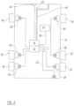
- FIG. 1 shows known features of a vehicle 10 which includes a tractor 12 and a trailer 14.
- the tractor 12 has a main braking electronic control unit (ECU) 16, together with a modulator 32.
- the tractor 12 has a plurality of wheels 26, each of which is provided with a brake 28, operated by an actuator 30.
- the actuators 30 are pneumatically operable, and are connected to a source of pressurised fluid (in this example compressed air) via the modulator 32.
- the modulator 32 is, in turn, controlled by an electrical signal input from the ECU 16.
- the trailer 14 has a trailer ECU 18 which sends control signals to a modulator 32.
- the trailer 14 also has a plurality of wheels 26, again each with a brake 28 which is operated by an actuator 30.
- each of the actuators 30 is connected to a source of pressurised fluid by the modulator 32.
- a series of connecting cables 20 extends from the tractor ECU 16, via a tractor connector 22 and a trailer connector 24, to the trailer ECU 18.
- the connecting cables 20 comprise a data connection such as a CAN bus. From the tractor connector 22 to the trailer ECU 18 the connecting cables 20 also include power cables. When the tractor 12 and trailer 14 are connected, it will be understood that the trailer ECU 18 is powered from the power circuit of the tractor 12.
- a telematics unit 36 is connected to the trailer ECU 18 by way of a connecting cable 38, which includes both a power cable and a data connection such as a CAN bus.
- the telematics unit 36 allows communication between the trailer ECU and a remote control centre, and is powered from the trailer ECU 18 via the connecting cable 38.
- the tractor 12 also includes a brake pedal 33 which is connected to a pneumatic line 34, which is connected both to the tractor ECU 16 and to the trailer ECU 18.
- a data logging apparatus suitable for use in relation to such a vehicle 10 is described in GB 2473688 .
- This document discloses a system including a data logging apparatus which has the ability to power the EBS unit from an independent power source, such as a rechargeable cell, when it detects that the EBS is in an unpowered condition, to obtain sensor data from the EBS, to obtain the time and/or data receipt of the data from a real time clock, and to store the sensor data, time and/or date in its memory.
- the data logging apparatus is programmed to obtain sensor data automatically on the basis of a duty cycle, as this enables data to be received from the sensor on the basis of a predetermined schedule.
- US 2008/0162968 discloses a system and method for power management in the tracking system of a trailer.
- the system in US 2008/0162968 includes a telematics unit which has a "wake” mode when the system is powered and available for remote communication, and a "sleep” mode in which the unit cannot communicate with a remote control centre.
- the unit assess the level of charge in its battery, and then determines how long it should remain in “wake” mode, and when it should switch to "sleep” mode, and for how long for.
- one aspect of the present invention provides a trailer comprising a power system, an electronic braking system (EBS) and a telematics unit having a battery, wherein a power connection is provided from the telematics unit to the EBS to provide power from the battery of the telematics unit to the EBS to power the EBS when the trailer is not connected to an external source of electrical power, characterised in that the trailer further comprises at least one sensor, and the powering of the EBS from the battery of the telematics unit is initiated in response to a signal from the sensor.
- EBS electronic braking system
- the battery is rechargeable and, when the trailer is connected to an external source of electrical power, may be charged from the external source of electrical power.
- the power system further comprises a control which may be operated by a user to trigger the powering of the EBS from the battery of the telematics unit.
- the senor is a weight or load sensor.
- the trailer has a load display, which is adapted to display information obtained from the EBS relating to a load on the trailer, and wherein the load display may be powered by the battery of the telematics unit.
- the trailer comprises an alerting device, which may provide an alert in response to a predetermined event, and the alerting device may be powered by the battery of the telematics unit.
- the predetermined event is an increase or decrease in the load sensed by a load sensor of the trailer.
- the EBS is powered by the battery of the telematics unit in response to a request received from an external control centre.
- the request is received via the telematics unit.
- the battery may power the EBS so that information may be transferred from the EBS to the telematics unit.
- the information is stored in a memory which is accessible by the EBS, and the EBS is powered by the battery so that the information can be retrieved.
- the information is gathered by the EBS before being transferred to the telematics unit, and the EBS is powered by the battery so that the information can be gathered.
- the power system further comprises a charge level sensor to measure the charge level of the battery of the telematics unit.
- the trailer EBS will not be powered by the battery of the telematics unit if the detected charge level of the battery of the telematics unit is below a predetermined level.
- a further aspect of the present invention provides a method of powering a vehicle trailer comprising an electronic braking system (EBS) and a telematics unit having a battery, and a sensor, the method comprising the step, when the trailer is not connected to an external source of electrical power, of providing power from the rechargeable battery of the telematics unit to the EBS via a power connection to power the EBS, characterised in that the powering of the EBS from the battery of the telematics unit is initiated in response to a signal from the sensor.
- EBS electronic braking system
- the telematics unit 36 it is common for the telematics unit 36 to contain a rechargeable battery, as well as GPS (location) and GSM (communication) modules. In normal use these modules are powered, and the battery is recharged, via the connecting cable 38 (although the battery may be charged by another route, for instance via the trailer's lighting circuit).
- GPS location
- GSM communication
- the telematics unit 36 may continue to operate for at least a limited time, powered from its internal rechargeable battery. This allows the telematics unit 36 to broadcast the position of the trailer 14 to the remote control centre.
- the trailer's electronic braking system which comprises the trailer ECU 18 and the associated modulator 32, may be powered by the battery of the telematics unit 36, in particular when the trailer 14 is not connected to an external source of electrical power. It will be understood that power may be delivered from the battery of the telematics unit 36 to the trailer ECU 18 (or to another part of the trailer EBS) via the connecting cable 38.
- the trailer EBS may be powered periodically, on request, and/or in response to a detected event, as described below.
- a load display 40 is provided on the trailer 14, and in the embodiment shown in figure 2 the load display 40 is connected to the trailer ECU 18 by a cable 42. If the trailer EBS is powered by the telematics unit 36 during a loading operation when the trailer 14 is not connected to a tractor, this load display 40 may be powered from the trailer ECU 18, thus allowing the load on the trailer 14 to be seen and monitored as the loading operation proceeds.
- Information as to the load on the trailer 14 may be derived, for example, from air bellows pressure sensors which are provided as part of the actuators 30, which are connected to the trailer EBS.
- Figures 1 and 2 show a "full" trailer with axles at the front and rear. However, it should be understood that the invention applies equally to semi-trailers, which have axles at the rear and are supported at the front either by the towing tractor or by landing legs.
- a trailer of this type will usually be parked with its landing legs down, and so the signals from the air bellows pressure sensors may only give an indication of the weight on the trailer suspension at the rear. However, in many operations this will be sufficient to give an indication of the trailer bogie overload, as when the tractor is connected in general the front of the trailer will be at approximately the same height as when parked on its landing legs. This means that the load on the trailer bogie will be around the same as the load in the coupled condition.
- the trailer EBS will be powered from the telematics unit 36 in response to a specific command from operators (e.g. a button on the load display 40 being pressed), or in response to a determination that the load on the trailer 14 has changed by more than a predetermined threshold, or in excess of a predetermined rate.
- operators e.g. a button on the load display 40 being pressed
- a trailer parked on its landing legs can tip forward when a forklift truck loads a very heavy pallet of goods onto to the front of the trailer with no load installed at the rear. If the trailer EBS is powered during a loading phase, however, the suspension pressure can be monitored and an alarm can be activated if the apparent load at the rear of the trailer is reduced by more than a predetermined amount, or if the apparent load at the rear of the trailer decreases at a rate that is in excess of a predetermined threshold rate.
- the alarm may comprise an audible signal such as a buzzer and/or a visual signal such as a light.
- a load display provided at a suitable location on the trailer, may be powered during this phase so that operators may monitor the load continuously.
- the powering of the trailer EBS during a loading phase may be activated by a specific command from an operator, or in response to a detected change in the load on the trailer.
- the trailer EBS will be powered by the telematics unit 36 for the minimum length of time, in order to conserve power in the battery of the telematics unit 36.
- the powering of the trailer EBS by the telematics unit 36 will, in preferred embodiments, cease upon a command from an operator (e.g. pressing on off switch) or if the detected load on the trailer 14 does not change (or changes by less than a threshold amount) for a predetermined length of time.
- the powering of the EBS may stop after a predetermined length of time.
- a control centre may send a message to the telematics unit 36 of the trailer 14, requesting a transfer of data stored in the memory of the trailer EBS.
- the telematics unit 36 may power the trailer EBS, retrieve the requested data from the memory, and transmit it to the control centre via the GSM link.
- information such as suspension pressure may be gathered by the EBS for transmission, rather than being retrieved from the memory.
- the powering of the trailer EBS by the telematics unit 36 will be initiated in response to the request from the control centre.
- the telematics unit 36 will power the trailer EBS for only as long as is necessary to retrieve the requested data from the EBS memory.
- a charge level sensor is provided in the telematics unit 36 (or elsewhere) to monitor the level of charge of the battery of the telematics unit 36. If the level of charge falls below a predetermined level, the telematics unit 36 may not power the vehicle EBS, to conserve power in order to fulfil the regular tasks of the telematics unit 36.
- the trailer EBS may be powered by the telematics unit 36 upon request, until the battery of the telematics unit 36 is entirely depleted.
- a "battery low” signal may be provided to an operator when the telematics unit 36 powers the trailer EBS, when the level of charge in the battery of the telematics unit 36 is below a preset level.
- the embodiments described above allow powering of the trailer EBS for particular tasks, while requiring minimum modification to the components of a known trailer system.
- the existing one-way power connection between the trailer EBS and the telematics unit 36 may be converted into a two-way power connection, and some hardware modification may be required in order to do so.
- a two-way data connection e.g. a CAN bus
- the EBS when the trailer 14 is not connected to an external source of electrical power the EBS may be powered via a USB cable, instead of by the battery of the telematics unit 36.
- a USB connection is provided at a suitable location on the trailer 14, which is readily accessible by an operator.
- the operator may connect to the trailer 14 a device such as a laptop computer, by plugging in a USB cable both to a USB socket on the laptop and to the trailer's USB connection.
- the EBS can be powered through this connection to gather or retrieve data, such as fault status or other parameters relating to the trailer, and the data can then be transmitted to the laptop through the USB cable.
Landscapes
- Engineering & Computer Science (AREA)
- Transportation (AREA)
- Mechanical Engineering (AREA)
- Physics & Mathematics (AREA)
- General Physics & Mathematics (AREA)
- Multimedia (AREA)
- Electric Propulsion And Braking For Vehicles (AREA)
- Arrangements For Transmission Of Measured Signals (AREA)
Description
- THIS INVENTION relates to a trailer power system, and in particular to a power system for the trailer of an articulated heavy goods vehicle.
-
Figure 1 shows known features of avehicle 10 which includes atractor 12 and atrailer 14. Thetractor 12 has a main braking electronic control unit (ECU) 16, together with amodulator 32. Thetractor 12 has a plurality ofwheels 26, each of which is provided with abrake 28, operated by anactuator 30. In this example, theactuators 30 are pneumatically operable, and are connected to a source of pressurised fluid (in this example compressed air) via themodulator 32. Themodulator 32 is, in turn, controlled by an electrical signal input from theECU 16. - Similarly, the
trailer 14 has a trailer ECU 18 which sends control signals to amodulator 32. Thetrailer 14 also has a plurality ofwheels 26, again each with abrake 28 which is operated by anactuator 30. As described above in relation to thetractor 12, each of theactuators 30 is connected to a source of pressurised fluid by themodulator 32. - A series of connecting
cables 20 extends from the tractor ECU 16, via atractor connector 22 and atrailer connector 24, to the trailer ECU 18. The connectingcables 20 comprise a data connection such as a CAN bus. From thetractor connector 22 to the trailer ECU 18 the connectingcables 20 also include power cables. When thetractor 12 andtrailer 14 are connected, it will be understood that the trailer ECU 18 is powered from the power circuit of thetractor 12. - A
telematics unit 36 is connected to the trailer ECU 18 by way of a connectingcable 38, which includes both a power cable and a data connection such as a CAN bus. Thetelematics unit 36 allows communication between the trailer ECU and a remote control centre, and is powered from the trailer ECU 18 via the connectingcable 38. - The
tractor 12 also includes abrake pedal 33 which is connected to apneumatic line 34, which is connected both to the tractor ECU 16 and to the trailer ECU 18. - The features described thus far are conventional.
- An embodiment of data logging apparatus suitable for use in relation to such a
vehicle 10 is described inGB 2473688 -
US 2008/0162968 discloses a system and method for power management in the tracking system of a trailer. - The system in
US 2008/0162968 includes a telematics unit which has a "wake" mode when the system is powered and available for remote communication, and a "sleep" mode in which the unit cannot communicate with a remote control centre. The unit assess the level of charge in its battery, and then determines how long it should remain in "wake" mode, and when it should switch to "sleep" mode, and for how long for. - It is an object of the present invention to provide an improved power system.
- Accordingly, one aspect of the present invention provides a trailer comprising a power system, an electronic braking system (EBS) and a telematics unit having a battery, wherein a power connection is provided from the telematics unit to the EBS to provide power from the battery of the telematics unit to the EBS to power the EBS when the trailer is not connected to an external source of electrical power, characterised in that the trailer further comprises at least one sensor, and the powering of the EBS from the battery of the telematics unit is initiated in response to a signal from the sensor.
- Advantageously, the battery is rechargeable and, when the trailer is connected to an external source of electrical power, may be charged from the external source of electrical power.
- Preferably, the power system further comprises a control which may be operated by a user to trigger the powering of the EBS from the battery of the telematics unit.
- Advantageously, the sensor is a weight or load sensor.
- Preferably, the trailer has a load display, which is adapted to display information obtained from the EBS relating to a load on the trailer, and wherein the load display may be powered by the battery of the telematics unit.
- Conveniently, the trailer comprises an alerting device, which may provide an alert in response to a predetermined event, and the alerting device may be powered by the battery of the telematics unit.
- Advantageously, the predetermined event is an increase or decrease in the load sensed by a load sensor of the trailer.
- Preferably, the EBS is powered by the battery of the telematics unit in response to a request received from an external control centre.
- Conveniently, the request is received via the telematics unit.
- Advantageously, the battery may power the EBS so that information may be transferred from the EBS to the telematics unit.
- Preferably, the information is stored in a memory which is accessible by the EBS, and the EBS is powered by the battery so that the information can be retrieved.
- Conveniently, the information is gathered by the EBS before being transferred to the telematics unit, and the EBS is powered by the battery so that the information can be gathered.
- Advantageously, the power system further comprises a charge level sensor to measure the charge level of the battery of the telematics unit.
- Preferably, the trailer EBS will not be powered by the battery of the telematics unit if the detected charge level of the battery of the telematics unit is below a predetermined level.
- A further aspect of the present invention provides a method of powering a vehicle trailer comprising an electronic braking system (EBS) and a telematics unit having a battery, and a sensor, the method comprising the step, when the trailer is not connected to an external source of electrical power, of providing power from the rechargeable battery of the telematics unit to the EBS via a power connection to power the EBS, characterised in that the powering of the EBS from the battery of the telematics unit is initiated in response to a signal from the sensor.
- In order that the present invention may be more readily understood embodiments thereof will now be described, by way of example, with reference to the accompanying drawings, in which:
-
Figure 1 shows a trailer including a power system embodying the present invention attached to a tractor; and -
Figure 2 shows the trailer offigure 1 detached from the tractor. - Referring again to
figure 1 , it is common for thetelematics unit 36 to contain a rechargeable battery, as well as GPS (location) and GSM (communication) modules. In normal use these modules are powered, and the battery is recharged, via the connecting cable 38 (although the battery may be charged by another route, for instance via the trailer's lighting circuit). - It is often the case that the
trailer 14 is not attached to a tractor, or to any other external power source, as shown infigure 2 . Thetelematics unit 36 may continue to operate for at least a limited time, powered from its internal rechargeable battery. This allows thetelematics unit 36 to broadcast the position of thetrailer 14 to the remote control centre. - In embodiments of the present invention, the trailer's electronic braking system (EBS), which comprises the trailer ECU 18 and the associated
modulator 32, may be powered by the battery of thetelematics unit 36, in particular when thetrailer 14 is not connected to an external source of electrical power. It will be understood that power may be delivered from the battery of thetelematics unit 36 to the trailer ECU 18 (or to another part of the trailer EBS) via the connectingcable 38. - The trailer EBS may be powered periodically, on request, and/or in response to a detected event, as described below.
- In some embodiments a load display 40 is provided on the
trailer 14, and in the embodiment shown infigure 2 the load display 40 is connected to the trailer ECU 18 by acable 42. If the trailer EBS is powered by thetelematics unit 36 during a loading operation when thetrailer 14 is not connected to a tractor, this load display 40 may be powered from the trailer ECU 18, thus allowing the load on thetrailer 14 to be seen and monitored as the loading operation proceeds. - Information as to the load on the
trailer 14 may be derived, for example, from air bellows pressure sensors which are provided as part of theactuators 30, which are connected to the trailer EBS. - Usually, when a loading operation is carried out when a trailer is disconnected from a tractor, there is no electrical power to the trailer and therefore operators will generally be unable to monitor with any accuracy the load that is placed on the trailer. If a discovery is made that the trailer is overloaded when the trailer is first connected to a tractor, this may cause significant delays while the load is adjusted. Providing power to the EBS to operate the load display 40 when the
trailer 14 is disconnected from a tractor is therefore useful and may potentially save significant amounts of time. -
Figures 1 and2 show a "full" trailer with axles at the front and rear. However, it should be understood that the invention applies equally to semi-trailers, which have axles at the rear and are supported at the front either by the towing tractor or by landing legs. - It is noted that a trailer of this type will usually be parked with its landing legs down, and so the signals from the air bellows pressure sensors may only give an indication of the weight on the trailer suspension at the rear. However, in many operations this will be sufficient to give an indication of the trailer bogie overload, as when the tractor is connected in general the front of the trailer will be at approximately the same height as when parked on its landing legs. This means that the load on the trailer bogie will be around the same as the load in the coupled condition.
- In preferred embodiments the trailer EBS will be powered from the
telematics unit 36 in response to a specific command from operators (e.g. a button on the load display 40 being pressed), or in response to a determination that the load on thetrailer 14 has changed by more than a predetermined threshold, or in excess of a predetermined rate. - In addition to the above, it is known that, in some cases, a trailer parked on its landing legs can tip forward when a forklift truck loads a very heavy pallet of goods onto to the front of the trailer with no load installed at the rear. If the trailer EBS is powered during a loading phase, however, the suspension pressure can be monitored and an alarm can be activated if the apparent load at the rear of the trailer is reduced by more than a predetermined amount, or if the apparent load at the rear of the trailer decreases at a rate that is in excess of a predetermined threshold rate.
- The alarm may comprise an audible signal such as a buzzer and/or a visual signal such as a light. Alternatively, or in addition, a load display, provided at a suitable location on the trailer, may be powered during this phase so that operators may monitor the load continuously.
- Again, the powering of the trailer EBS during a loading phase may be activated by a specific command from an operator, or in response to a detected change in the load on the trailer.
- In general it is envisaged that the trailer EBS will be powered by the
telematics unit 36 for the minimum length of time, in order to conserve power in the battery of thetelematics unit 36. The powering of the trailer EBS by thetelematics unit 36 will, in preferred embodiments, cease upon a command from an operator (e.g. pressing on off switch) or if the detected load on thetrailer 14 does not change (or changes by less than a threshold amount) for a predetermined length of time. Alternatively or in addition the powering of the EBS may stop after a predetermined length of time. - In a further example, a control centre may send a message to the
telematics unit 36 of thetrailer 14, requesting a transfer of data stored in the memory of the trailer EBS. In embodiments of the present invention, if a request of this nature is received and thetrailer 14 is not connected to an external power source, thetelematics unit 36 may power the trailer EBS, retrieve the requested data from the memory, and transmit it to the control centre via the GSM link. In other embodiments information such as suspension pressure may be gathered by the EBS for transmission, rather than being retrieved from the memory. - In this case, the powering of the trailer EBS by the
telematics unit 36 will be initiated in response to the request from the control centre. - It is proposed that the
telematics unit 36 will power the trailer EBS for only as long as is necessary to retrieve the requested data from the EBS memory. - In preferred embodiments of the invention a charge level sensor is provided in the telematics unit 36 (or elsewhere) to monitor the level of charge of the battery of the
telematics unit 36. If the level of charge falls below a predetermined level, thetelematics unit 36 may not power the vehicle EBS, to conserve power in order to fulfil the regular tasks of thetelematics unit 36. - In alternative embodiments of the invention, the trailer EBS may be powered by the
telematics unit 36 upon request, until the battery of thetelematics unit 36 is entirely depleted. - In embodiments of the invention, a "battery low" signal may be provided to an operator when the
telematics unit 36 powers the trailer EBS, when the level of charge in the battery of thetelematics unit 36 is below a preset level. - The embodiments described above allow powering of the trailer EBS for particular tasks, while requiring minimum modification to the components of a known trailer system. In particular, the existing one-way power connection between the trailer EBS and the
telematics unit 36 may be converted into a two-way power connection, and some hardware modification may be required in order to do so. In a conventional trailer there will already be a two-way data connection (e.g. a CAN bus) between the trailer EBS and thetelematics unit 36, and it is therefore envisaged that little or no modification in this regard will be required. - In other embodiments of this invention, when the
trailer 14 is not connected to an external source of electrical power the EBS may be powered via a USB cable, instead of by the battery of thetelematics unit 36. For this to be possible a USB connection is provided at a suitable location on thetrailer 14, which is readily accessible by an operator. The operator may connect to the trailer 14 a device such as a laptop computer, by plugging in a USB cable both to a USB socket on the laptop and to the trailer's USB connection. The EBS can be powered through this connection to gather or retrieve data, such as fault status or other parameters relating to the trailer, and the data can then be transmitted to the laptop through the USB cable. - It will be understood that this allows the EBS to be powered and interrogated in one simple step, using a standard type of connection. This makes it quick and easy for an operator to gather information from the trailer without using specialised equipment.
- When used in this specification and claims, the terms "comprises" and "comprising" and variations thereof mean that the specified features, steps or integers are included. The terms are not to be interpreted to exclude the presence of other features, steps or components.
Claims (14)
- A trailer comprising a power system, an electronic braking system (EBS) (18, 32) and a telematics unit (36) having a battery, wherein a power connection (38) is provided from the telematics unit (36) to the EBS to provide power from the battery of the telematics unit (36) to the EBS (18, 32) to power the EBS (18, 32) when the trailer is not connected to an external source of electrical power, characterised in that the trailer further comprises at least one sensor, and the powering of the EBS (18, 32) from the battery of the telematics unit (36) is initiated in response to a signal from the sensor.
- A trailer according to claim 1, further comprising a control which may be operated by a user to trigger the powering of the EBS (18, 32) from the battery of the telematics unit (36).
- A trailer according to claim 1 or 2, wherein the sensor is a weight or load sensor.
- A trailer according to any preceding claim wherein the system has a load display, which is adapted to display information obtained from the EBS relating to a load on the trailer, and wherein the load display may be powered by the battery of the telematics unit (36).
- A trailer according to any preceding claim wherein the trailer comprises an alerting device, which may provide an alert in response to a predetermined event, and the alerting device may be powered by the battery of the telematics unit (36).
- A trailer according to claim 5, wherein the predetermined event is an increase or decrease in the load sensed by a load sensor of the trailer.
- A trailer according to any preceding claim wherein the EBS (18, 32) is powered by the battery of the telematics unit (36) in response to a request received from an external control centre.
- A trailer according to claim 7, wherein the request is received via the telematics unit (36).
- A trailer according to any preceding claim wherein the battery powers the EBS (18, 32) so that information may be transferred from the EBS (18, 32) to the telematics unit (36).
- A trailer according to claim 9 wherein the information is stored in a memory which is accessible by the EBS (18, 32), and the EBS (18, 32) is powered by the battery so that the information can be retrieved.
- A trailer according to claim 9 or 10 wherein the information is gathered by the EBS (18, 32) before being transferred to the telematics unit (36), and the EBS (18, 32) is powered by the battery so that the information can be gathered.
- A trailer according to any preceding claim further comprising a charge level sensor to measure the charge level of the battery of the telematics unit (36).
- A trailer according to claim 8 wherein the EBS (18, 32) will not be powered by the battery of the telematics unit (36) if the detected charge level of the battery of the telematics unit (36) is below a predetermined level.
- A method of powering a vehicle trailer (14) comprising an electronic braking system (EBS) (148, 32), a telematics unit (36) having a battery, and a sensor, the method comprising the step of, when the trailer (14) is not connected to an external source of electrical power, of providing power from the rechargeable battery of the telematics unit (36) to the EBS (18, 32) via a power connection to power the EBS (18, 32), characterised in that the powering of the EBS (18, 32) from the battery of the telematics unit (36) is initiated in response to a signal from the sensor.
Applications Claiming Priority (2)
| Application Number | Priority Date | Filing Date | Title |
|---|---|---|---|
| GB1222443.2A GB2508856B (en) | 2012-12-13 | 2012-12-13 | Trailer power system |
| PCT/GB2013/053252 WO2014091224A1 (en) | 2012-12-13 | 2013-12-10 | Trailer power system |
Publications (3)
| Publication Number | Publication Date |
|---|---|
| EP2931571A1 EP2931571A1 (en) | 2015-10-21 |
| EP2931571B1 EP2931571B1 (en) | 2020-10-14 |
| EP2931571B2 true EP2931571B2 (en) | 2025-01-22 |
Family
ID=47602528
Family Applications (1)
| Application Number | Title | Priority Date | Filing Date |
|---|---|---|---|
| EP13808181.5A Active EP2931571B2 (en) | 2012-12-13 | 2013-12-10 | Trailer power system |
Country Status (3)
| Country | Link |
|---|---|
| EP (1) | EP2931571B2 (en) |
| GB (1) | GB2508856B (en) |
| WO (1) | WO2014091224A1 (en) |
Citations (12)
| Publication number | Priority date | Publication date | Assignee | Title |
|---|---|---|---|---|
| US1861770A (en) † | 1928-09-01 | 1932-06-07 | Warner Electric Brake Corp | Trailer brake control |
| GB1446792A (en) † | 1974-09-09 | 1976-08-18 | Tekonsha Eng Co | Towed vehicle electric brake control |
| US4033630A (en) † | 1975-09-22 | 1977-07-05 | Motor Wheel Corporation | Remote control circuit for electric trailer brakes |
| CA1030249A (en) † | 1974-09-10 | 1978-04-25 | Tekonsha Engineering Company | Towed vehicle electric brake control |
| DE3714193A1 (en) † | 1987-04-29 | 1988-11-10 | Bosch Gmbh Robert | POWER SUPPLY FOR ELECTRONIC DEVICES, ESPECIALLY FOR SAFETY-RELEVANT DEVICES IN MOTOR VEHICLES |
| DE9215061U1 (en) † | 1992-11-05 | 1993-06-09 | Lubs, Wolfgang, 5000 Köln | Electronic automatic braking |
| US5949147A (en) † | 1996-05-24 | 1999-09-07 | Hayes Lemmerz International, Inc. | Short circuit safety audible monitor |
| WO2001051326A1 (en) † | 2000-01-11 | 2001-07-19 | Wabash Technology Corporation | Braking system with wireless communication capability and trailer including same |
| EP1118965A1 (en) † | 2000-01-07 | 2001-07-25 | General Trailers France | Controlling apparatus of a road vehicle and onboard electronic system comprising such a device |
| WO2005107362A2 (en) † | 2004-02-03 | 2005-11-17 | Haldex Brake Products Ab | Vehicle telematics system |
| EP2058627A2 (en) † | 2007-11-08 | 2009-05-13 | Haldex Brake Products Limited | Vehicle odometer system |
| WO2011117595A1 (en) † | 2010-03-23 | 2011-09-29 | Axscend Limited | Data logging apparatus for a vehicle |
Family Cites Families (1)
| Publication number | Priority date | Publication date | Assignee | Title |
|---|---|---|---|---|
| US7546477B2 (en) * | 2006-12-29 | 2009-06-09 | General Electric Company | Wake interval adjustment based on charge level |
-
2012
- 2012-12-13 GB GB1222443.2A patent/GB2508856B/en active Active
-
2013
- 2013-12-10 EP EP13808181.5A patent/EP2931571B2/en active Active
- 2013-12-10 WO PCT/GB2013/053252 patent/WO2014091224A1/en not_active Ceased
Patent Citations (12)
| Publication number | Priority date | Publication date | Assignee | Title |
|---|---|---|---|---|
| US1861770A (en) † | 1928-09-01 | 1932-06-07 | Warner Electric Brake Corp | Trailer brake control |
| GB1446792A (en) † | 1974-09-09 | 1976-08-18 | Tekonsha Eng Co | Towed vehicle electric brake control |
| CA1030249A (en) † | 1974-09-10 | 1978-04-25 | Tekonsha Engineering Company | Towed vehicle electric brake control |
| US4033630A (en) † | 1975-09-22 | 1977-07-05 | Motor Wheel Corporation | Remote control circuit for electric trailer brakes |
| DE3714193A1 (en) † | 1987-04-29 | 1988-11-10 | Bosch Gmbh Robert | POWER SUPPLY FOR ELECTRONIC DEVICES, ESPECIALLY FOR SAFETY-RELEVANT DEVICES IN MOTOR VEHICLES |
| DE9215061U1 (en) † | 1992-11-05 | 1993-06-09 | Lubs, Wolfgang, 5000 Köln | Electronic automatic braking |
| US5949147A (en) † | 1996-05-24 | 1999-09-07 | Hayes Lemmerz International, Inc. | Short circuit safety audible monitor |
| EP1118965A1 (en) † | 2000-01-07 | 2001-07-25 | General Trailers France | Controlling apparatus of a road vehicle and onboard electronic system comprising such a device |
| WO2001051326A1 (en) † | 2000-01-11 | 2001-07-19 | Wabash Technology Corporation | Braking system with wireless communication capability and trailer including same |
| WO2005107362A2 (en) † | 2004-02-03 | 2005-11-17 | Haldex Brake Products Ab | Vehicle telematics system |
| EP2058627A2 (en) † | 2007-11-08 | 2009-05-13 | Haldex Brake Products Limited | Vehicle odometer system |
| WO2011117595A1 (en) † | 2010-03-23 | 2011-09-29 | Axscend Limited | Data logging apparatus for a vehicle |
Also Published As
| Publication number | Publication date |
|---|---|
| WO2014091224A1 (en) | 2014-06-19 |
| EP2931571B1 (en) | 2020-10-14 |
| EP2931571A1 (en) | 2015-10-21 |
| GB201222443D0 (en) | 2013-01-23 |
| GB2508856A (en) | 2014-06-18 |
| GB2508856B (en) | 2019-11-20 |
Similar Documents
| Publication | Publication Date | Title |
|---|---|---|
| US11938766B2 (en) | Communication device, system, and method for active control of external vehicle components | |
| US12589719B2 (en) | Remote control of a brake controller for a towed vehicle | |
| CN110062917A (en) | Intelligent tow truck system | |
| US11912325B2 (en) | Systems and methods for improved automatic chocking of a cargo dolly | |
| US20150349977A1 (en) | Method and System for Transmitting Telematics Data from a Truck to a Telematics Portal | |
| US10895492B2 (en) | Monitoring system for determining a vehicle safety setting based on weight | |
| US12162363B2 (en) | Modular system for dynamic tow and regenerative braking of a trailer | |
| CN104339999A (en) | Hitch detecting system | |
| US11227451B2 (en) | Monitoring system for determining a vehicle maintenance condition based on weight | |
| US20250369814A1 (en) | System and method for dynamic tow of a trailer | |
| US20240067278A1 (en) | System and method for dynamic tow of a trailer | |
| EP2931571B2 (en) | Trailer power system | |
| US20250256668A1 (en) | Smart Trailer Power Supply | |
| AU2012101599B4 (en) | Improved Trailer Brake Control System | |
| US11945339B2 (en) | Energy management system for a towed vehicle | |
| EP3093166B1 (en) | Tyre pressure monitoring module | |
| US20240270215A1 (en) | Electric over hydraulic braking system | |
| CN210293413U (en) | Vehicle-mounted self-weight device | |
| EP2550643B1 (en) | Data logging apparatus for a vehicle | |
| WO2019053022A1 (en) | System and method for a trailer towable by a vehicle | |
| CN119309657A (en) | Railway freight car overload and unbalanced load detection system and railway freight car | |
| CN113806603A (en) | Intelligent online weighing management method, system, equipment and medium for vehicle | |
| CN112875046A (en) | Electronic commerce goods transfer system | |
| NZ617020B (en) | Improved Trailer Brake Control System |
Legal Events
| Date | Code | Title | Description |
|---|---|---|---|
| PUAI | Public reference made under article 153(3) epc to a published international application that has entered the european phase |
Free format text: ORIGINAL CODE: 0009012 |
|
| 17P | Request for examination filed |
Effective date: 20150608 |
|
| AK | Designated contracting states |
Kind code of ref document: A1 Designated state(s): AL AT BE BG CH CY CZ DE DK EE ES FI FR GB GR HR HU IE IS IT LI LT LU LV MC MK MT NL NO PL PT RO RS SE SI SK SM TR |
|
| AX | Request for extension of the european patent |
Extension state: BA ME |
|
| DAX | Request for extension of the european patent (deleted) | ||
| RAP1 | Party data changed (applicant data changed or rights of an application transferred) |
Owner name: HALDEX BRAKE PRODUCTS AB |
|
| GRAP | Despatch of communication of intention to grant a patent |
Free format text: ORIGINAL CODE: EPIDOSNIGR1 |
|
| STAA | Information on the status of an ep patent application or granted ep patent |
Free format text: STATUS: GRANT OF PATENT IS INTENDED |
|
| INTG | Intention to grant announced |
Effective date: 20200506 |
|
| GRAS | Grant fee paid |
Free format text: ORIGINAL CODE: EPIDOSNIGR3 |
|
| GRAA | (expected) grant |
Free format text: ORIGINAL CODE: 0009210 |
|
| STAA | Information on the status of an ep patent application or granted ep patent |
Free format text: STATUS: THE PATENT HAS BEEN GRANTED |
|
| AK | Designated contracting states |
Kind code of ref document: B1 Designated state(s): AL AT BE BG CH CY CZ DE DK EE ES FI FR GB GR HR HU IE IS IT LI LT LU LV MC MK MT NL NO PL PT RO RS SE SI SK SM TR |
|
| REG | Reference to a national code |
Ref country code: GB Ref legal event code: FG4D |
|
| REG | Reference to a national code |
Ref country code: AT Ref legal event code: REF Ref document number: 1323277 Country of ref document: AT Kind code of ref document: T Effective date: 20201015 Ref country code: CH Ref legal event code: EP |
|
| REG | Reference to a national code |
Ref country code: DE Ref legal event code: R096 Ref document number: 602013073311 Country of ref document: DE |
|
| REG | Reference to a national code |
Ref country code: IE Ref legal event code: FG4D |
|
| REG | Reference to a national code |
Ref country code: AT Ref legal event code: MK05 Ref document number: 1323277 Country of ref document: AT Kind code of ref document: T Effective date: 20201014 |
|
| REG | Reference to a national code |
Ref country code: NL Ref legal event code: MP Effective date: 20201014 |
|
| PG25 | Lapsed in a contracting state [announced via postgrant information from national office to epo] |
Ref country code: GR Free format text: LAPSE BECAUSE OF FAILURE TO SUBMIT A TRANSLATION OF THE DESCRIPTION OR TO PAY THE FEE WITHIN THE PRESCRIBED TIME-LIMIT Effective date: 20210115 Ref country code: PT Free format text: LAPSE BECAUSE OF FAILURE TO SUBMIT A TRANSLATION OF THE DESCRIPTION OR TO PAY THE FEE WITHIN THE PRESCRIBED TIME-LIMIT Effective date: 20210215 Ref country code: NO Free format text: LAPSE BECAUSE OF FAILURE TO SUBMIT A TRANSLATION OF THE DESCRIPTION OR TO PAY THE FEE WITHIN THE PRESCRIBED TIME-LIMIT Effective date: 20210114 Ref country code: NL Free format text: LAPSE BECAUSE OF FAILURE TO SUBMIT A TRANSLATION OF THE DESCRIPTION OR TO PAY THE FEE WITHIN THE PRESCRIBED TIME-LIMIT Effective date: 20201014 Ref country code: FI Free format text: LAPSE BECAUSE OF FAILURE TO SUBMIT A TRANSLATION OF THE DESCRIPTION OR TO PAY THE FEE WITHIN THE PRESCRIBED TIME-LIMIT Effective date: 20201014 Ref country code: RS Free format text: LAPSE BECAUSE OF FAILURE TO SUBMIT A TRANSLATION OF THE DESCRIPTION OR TO PAY THE FEE WITHIN THE PRESCRIBED TIME-LIMIT Effective date: 20201014 |
|
| REG | Reference to a national code |
Ref country code: LT Ref legal event code: MG4D |
|
| PG25 | Lapsed in a contracting state [announced via postgrant information from national office to epo] |
Ref country code: BG Free format text: LAPSE BECAUSE OF FAILURE TO SUBMIT A TRANSLATION OF THE DESCRIPTION OR TO PAY THE FEE WITHIN THE PRESCRIBED TIME-LIMIT Effective date: 20210114 Ref country code: ES Free format text: LAPSE BECAUSE OF FAILURE TO SUBMIT A TRANSLATION OF THE DESCRIPTION OR TO PAY THE FEE WITHIN THE PRESCRIBED TIME-LIMIT Effective date: 20201014 Ref country code: AT Free format text: LAPSE BECAUSE OF FAILURE TO SUBMIT A TRANSLATION OF THE DESCRIPTION OR TO PAY THE FEE WITHIN THE PRESCRIBED TIME-LIMIT Effective date: 20201014 Ref country code: IS Free format text: LAPSE BECAUSE OF FAILURE TO SUBMIT A TRANSLATION OF THE DESCRIPTION OR TO PAY THE FEE WITHIN THE PRESCRIBED TIME-LIMIT Effective date: 20210214 Ref country code: PL Free format text: LAPSE BECAUSE OF FAILURE TO SUBMIT A TRANSLATION OF THE DESCRIPTION OR TO PAY THE FEE WITHIN THE PRESCRIBED TIME-LIMIT Effective date: 20201014 Ref country code: SE Free format text: LAPSE BECAUSE OF FAILURE TO SUBMIT A TRANSLATION OF THE DESCRIPTION OR TO PAY THE FEE WITHIN THE PRESCRIBED TIME-LIMIT Effective date: 20201014 Ref country code: LV Free format text: LAPSE BECAUSE OF FAILURE TO SUBMIT A TRANSLATION OF THE DESCRIPTION OR TO PAY THE FEE WITHIN THE PRESCRIBED TIME-LIMIT Effective date: 20201014 |
|
| PG25 | Lapsed in a contracting state [announced via postgrant information from national office to epo] |
Ref country code: HR Free format text: LAPSE BECAUSE OF FAILURE TO SUBMIT A TRANSLATION OF THE DESCRIPTION OR TO PAY THE FEE WITHIN THE PRESCRIBED TIME-LIMIT Effective date: 20201014 |
|
| REG | Reference to a national code |
Ref country code: DE Ref legal event code: R026 Ref document number: 602013073311 Country of ref document: DE |
|
| PLBI | Opposition filed |
Free format text: ORIGINAL CODE: 0009260 |
|
| PLAX | Notice of opposition and request to file observation + time limit sent |
Free format text: ORIGINAL CODE: EPIDOSNOBS2 |
|
| PG25 | Lapsed in a contracting state [announced via postgrant information from national office to epo] |
Ref country code: LT Free format text: LAPSE BECAUSE OF FAILURE TO SUBMIT A TRANSLATION OF THE DESCRIPTION OR TO PAY THE FEE WITHIN THE PRESCRIBED TIME-LIMIT Effective date: 20201014 Ref country code: SK Free format text: LAPSE BECAUSE OF FAILURE TO SUBMIT A TRANSLATION OF THE DESCRIPTION OR TO PAY THE FEE WITHIN THE PRESCRIBED TIME-LIMIT Effective date: 20201014 Ref country code: RO Free format text: LAPSE BECAUSE OF FAILURE TO SUBMIT A TRANSLATION OF THE DESCRIPTION OR TO PAY THE FEE WITHIN THE PRESCRIBED TIME-LIMIT Effective date: 20201014 Ref country code: SM Free format text: LAPSE BECAUSE OF FAILURE TO SUBMIT A TRANSLATION OF THE DESCRIPTION OR TO PAY THE FEE WITHIN THE PRESCRIBED TIME-LIMIT Effective date: 20201014 Ref country code: CZ Free format text: LAPSE BECAUSE OF FAILURE TO SUBMIT A TRANSLATION OF THE DESCRIPTION OR TO PAY THE FEE WITHIN THE PRESCRIBED TIME-LIMIT Effective date: 20201014 Ref country code: EE Free format text: LAPSE BECAUSE OF FAILURE TO SUBMIT A TRANSLATION OF THE DESCRIPTION OR TO PAY THE FEE WITHIN THE PRESCRIBED TIME-LIMIT Effective date: 20201014 |
|
| REG | Reference to a national code |
Ref country code: CH Ref legal event code: PL |
|
| 26 | Opposition filed |
Opponent name: AXSCEND LIMITED Effective date: 20210713 |
|
| PG25 | Lapsed in a contracting state [announced via postgrant information from national office to epo] |
Ref country code: DK Free format text: LAPSE BECAUSE OF FAILURE TO SUBMIT A TRANSLATION OF THE DESCRIPTION OR TO PAY THE FEE WITHIN THE PRESCRIBED TIME-LIMIT Effective date: 20201014 Ref country code: MC Free format text: LAPSE BECAUSE OF FAILURE TO SUBMIT A TRANSLATION OF THE DESCRIPTION OR TO PAY THE FEE WITHIN THE PRESCRIBED TIME-LIMIT Effective date: 20201014 |
|
| REG | Reference to a national code |
Ref country code: BE Ref legal event code: MM Effective date: 20201231 |
|
| PG25 | Lapsed in a contracting state [announced via postgrant information from national office to epo] |
Ref country code: AL Free format text: LAPSE BECAUSE OF FAILURE TO SUBMIT A TRANSLATION OF THE DESCRIPTION OR TO PAY THE FEE WITHIN THE PRESCRIBED TIME-LIMIT Effective date: 20201014 Ref country code: LU Free format text: LAPSE BECAUSE OF NON-PAYMENT OF DUE FEES Effective date: 20201210 Ref country code: IE Free format text: LAPSE BECAUSE OF NON-PAYMENT OF DUE FEES Effective date: 20201210 Ref country code: IT Free format text: LAPSE BECAUSE OF FAILURE TO SUBMIT A TRANSLATION OF THE DESCRIPTION OR TO PAY THE FEE WITHIN THE PRESCRIBED TIME-LIMIT Effective date: 20201014 |
|
| PG25 | Lapsed in a contracting state [announced via postgrant information from national office to epo] |
Ref country code: SI Free format text: LAPSE BECAUSE OF FAILURE TO SUBMIT A TRANSLATION OF THE DESCRIPTION OR TO PAY THE FEE WITHIN THE PRESCRIBED TIME-LIMIT Effective date: 20201014 Ref country code: LI Free format text: LAPSE BECAUSE OF NON-PAYMENT OF DUE FEES Effective date: 20201231 Ref country code: CH Free format text: LAPSE BECAUSE OF NON-PAYMENT OF DUE FEES Effective date: 20201231 |
|
| PLBB | Reply of patent proprietor to notice(s) of opposition received |
Free format text: ORIGINAL CODE: EPIDOSNOBS3 |
|
| PG25 | Lapsed in a contracting state [announced via postgrant information from national office to epo] |
Ref country code: IS Free format text: LAPSE BECAUSE OF FAILURE TO SUBMIT A TRANSLATION OF THE DESCRIPTION OR TO PAY THE FEE WITHIN THE PRESCRIBED TIME-LIMIT Effective date: 20210214 Ref country code: TR Free format text: LAPSE BECAUSE OF FAILURE TO SUBMIT A TRANSLATION OF THE DESCRIPTION OR TO PAY THE FEE WITHIN THE PRESCRIBED TIME-LIMIT Effective date: 20201014 Ref country code: MT Free format text: LAPSE BECAUSE OF FAILURE TO SUBMIT A TRANSLATION OF THE DESCRIPTION OR TO PAY THE FEE WITHIN THE PRESCRIBED TIME-LIMIT Effective date: 20201014 Ref country code: CY Free format text: LAPSE BECAUSE OF FAILURE TO SUBMIT A TRANSLATION OF THE DESCRIPTION OR TO PAY THE FEE WITHIN THE PRESCRIBED TIME-LIMIT Effective date: 20201014 |
|
| PG25 | Lapsed in a contracting state [announced via postgrant information from national office to epo] |
Ref country code: MK Free format text: LAPSE BECAUSE OF FAILURE TO SUBMIT A TRANSLATION OF THE DESCRIPTION OR TO PAY THE FEE WITHIN THE PRESCRIBED TIME-LIMIT Effective date: 20201014 |
|
| PG25 | Lapsed in a contracting state [announced via postgrant information from national office to epo] |
Ref country code: BE Free format text: LAPSE BECAUSE OF NON-PAYMENT OF DUE FEES Effective date: 20201231 |
|
| PLBP | Opposition withdrawn |
Free format text: ORIGINAL CODE: 0009264 |
|
| P01 | Opt-out of the competence of the unified patent court (upc) registered |
Effective date: 20230602 |
|
| P02 | Opt-out of the competence of the unified patent court (upc) changed |
Effective date: 20230619 |
|
| PLAY | Examination report in opposition despatched + time limit |
Free format text: ORIGINAL CODE: EPIDOSNORE2 |
|
| REG | Reference to a national code |
Ref country code: DE Ref legal event code: R082 Ref document number: 602013073311 Country of ref document: DE Representative=s name: MUELLER SCHUPFNER & PARTNER PATENT- UND RECHTS, DE |
|
| PLBC | Reply to examination report in opposition received |
Free format text: ORIGINAL CODE: EPIDOSNORE3 |
|
| REG | Reference to a national code |
Ref country code: GB Ref legal event code: 732E Free format text: REGISTERED BETWEEN 20240404 AND 20240410 |
|
| REG | Reference to a national code |
Ref country code: DE Ref legal event code: R081 Ref document number: 602013073311 Country of ref document: DE Owner name: HALDEX AB, SE Free format text: FORMER OWNER: HALDEX BRAKE PRODUCTS AB, LANDSKRONA, SE |
|
| PUAH | Patent maintained in amended form |
Free format text: ORIGINAL CODE: 0009272 |
|
| STAA | Information on the status of an ep patent application or granted ep patent |
Free format text: STATUS: PATENT MAINTAINED AS AMENDED |
|
| 27A | Patent maintained in amended form |
Effective date: 20250122 |
|
| AK | Designated contracting states |
Kind code of ref document: B2 Designated state(s): AL AT BE BG CH CY CZ DE DK EE ES FI FR GB GR HR HU IE IS IT LI LT LU LV MC MK MT NL NO PL PT RO RS SE SI SK SM TR |
|
| REG | Reference to a national code |
Ref country code: DE Ref legal event code: R102 Ref document number: 602013073311 Country of ref document: DE |
|
| PGFP | Annual fee paid to national office [announced via postgrant information from national office to epo] |
Ref country code: DE Payment date: 20251125 Year of fee payment: 13 |
|
| PGFP | Annual fee paid to national office [announced via postgrant information from national office to epo] |
Ref country code: GB Payment date: 20251218 Year of fee payment: 13 |
|
| PGFP | Annual fee paid to national office [announced via postgrant information from national office to epo] |
Ref country code: FR Payment date: 20251217 Year of fee payment: 13 |