EP2931091B1 - Capsule or cartridge and infusion assembly for the preparation of a beverage, in particular coffee - Google Patents
Capsule or cartridge and infusion assembly for the preparation of a beverage, in particular coffee Download PDFInfo
- Publication number
- EP2931091B1 EP2931091B1 EP13826950.1A EP13826950A EP2931091B1 EP 2931091 B1 EP2931091 B1 EP 2931091B1 EP 13826950 A EP13826950 A EP 13826950A EP 2931091 B1 EP2931091 B1 EP 2931091B1
- Authority
- EP
- European Patent Office
- Prior art keywords
- capsule
- projections
- recesses
- cartridge
- flange
- Prior art date
- Legal status (The legal status is an assumption and is not a legal conclusion. Google has not performed a legal analysis and makes no representation as to the accuracy of the status listed.)
- Active
Links
Images





Classifications
-
- A—HUMAN NECESSITIES
- A47—FURNITURE; DOMESTIC ARTICLES OR APPLIANCES; COFFEE MILLS; SPICE MILLS; SUCTION CLEANERS IN GENERAL
- A47J—KITCHEN EQUIPMENT; COFFEE MILLS; SPICE MILLS; APPARATUS FOR MAKING BEVERAGES
- A47J31/00—Apparatus for making beverages
- A47J31/44—Parts or details or accessories of beverage-making apparatus
- A47J31/4492—Means to read code provided on ingredient pod or cartridge
-
- A—HUMAN NECESSITIES
- A47—FURNITURE; DOMESTIC ARTICLES OR APPLIANCES; COFFEE MILLS; SPICE MILLS; SUCTION CLEANERS IN GENERAL
- A47J—KITCHEN EQUIPMENT; COFFEE MILLS; SPICE MILLS; APPARATUS FOR MAKING BEVERAGES
- A47J31/00—Apparatus for making beverages
- A47J31/40—Beverage-making apparatus with dispensing means for adding a measured quantity of ingredients, e.g. coffee, water, sugar, cocoa, milk, tea
- A47J31/407—Beverage-making apparatus with dispensing means for adding a measured quantity of ingredients, e.g. coffee, water, sugar, cocoa, milk, tea with ingredient-containing cartridges; Cartridge-perforating means
-
- B—PERFORMING OPERATIONS; TRANSPORTING
- B65—CONVEYING; PACKING; STORING; HANDLING THIN OR FILAMENTARY MATERIAL
- B65D—CONTAINERS FOR STORAGE OR TRANSPORT OF ARTICLES OR MATERIALS, e.g. BAGS, BARRELS, BOTTLES, BOXES, CANS, CARTONS, CRATES, DRUMS, JARS, TANKS, HOPPERS, FORWARDING CONTAINERS; ACCESSORIES, CLOSURES, OR FITTINGS THEREFOR; PACKAGING ELEMENTS; PACKAGES
- B65D85/00—Containers, packaging elements or packages, specially adapted for particular articles or materials
- B65D85/70—Containers, packaging elements or packages, specially adapted for particular articles or materials for materials not otherwise provided for
- B65D85/804—Disposable containers or packages with contents which are mixed, infused or dissolved in situ, i.e. without having been previously removed from the package
- B65D85/8043—Packages adapted to allow liquid to pass through the contents
- B65D85/8058—Coding means for the contents
Definitions
- the present invention relates, in general, to the preparation of beverages by extraction under pressure with the use of capsules or cartridges.
- the invention relates to a capsule or cartridge of the type defined in the preamble of claim 1.
- a capsule or cartridge of that type is disclosed in EP 0 638 486 A1 .
- US 5 243 164 A discloses a capsule or cartridge of that type, wherein the lateral projections and recesses are uniformly spaced and are provided only for strengthening the lateral walls.
- WO 2012/010317 A1 describes and illustrates several embodiments of capsules.
- Figure 1 of this document illustrates a solution in which the lateral wall of the cup-shaped body of a capsule has a plurality of parallel circular annular projections, the longitudinal profile of which defines an identification of the capsule, "readable” by means of an optical detector.
- Figures 18-22 of said document illustrate another capsule in which the lateral wall of the cup-shaped body has identification projections and recesses, evenly spaced around the circumference thereof, forming a toothed crown. The number, size and spacing of the projections define mechanical identification of the capsule.
- WO 2012/028290 A1 DE 10 2011 010 534 A1 and EP 1 849 718 A1 disclose capsules with lateral walls provided with projections and recesses intended to allow the use, in a corresponding brewing machine, of only those capsules having a predetermined transverse profile.
- US 2011/0250319 A1 discloses a capsule having a corrugated top flange.
- EP 1 890 271 A1 describes and illustrates solutions based on the use of RFID tags to define an identification of capsules or cartridges for use in a machine for the preparation of beverages provided with an RFID reader.
- an RFID tag containing information that identifies the capsule and how it is to be used in the machine, is applied to a perimeter configuration in the form of flanges on each capsule or cartridge.
- the cup-shaped body in proximity to the flange-like formation, has at least one essentially planar lateral wall portion or face in which there is provided said plurality of projections and recesses.
- the cup-shaped body of a capsule according to the invention may have at least two external lateral wall portions or faces which are essentially planar and parallel with each other and in which there are provided respective pluralities of identification projections and recesses.
- the cup-shaped body may have four external lateral wall portions or faces which are essentially planar and parallel each to another one, and in which there are provided respective pluralities of projections and recesses.
- the cup-shaped body of a capsule according to the invention has a first lateral wall portion whose transverse cross-section, from the bottom wall to the flange-like formation, passes gradually from an essentially circular shape to an at least approximately quadrangular shape.
- the cup-shaped body conveniently has a second wall portion which is essentially prismatic, with a transverse cross-section having an essentially quadrangular shape, with preferably rounded and externally convex vertexes, and in which there are provided said lateral planar faces with the identification projections/recesses.
- a further object of the present invention is to provide an infusion assembly for a machine for the preparation of beverages with the use of capsules or cartridges having the features defined in Claim 1 and optionally the features defined in the claims which are dependent on Claim 1.
- Figures 1 and 2 show (general reference sign 1) a capsule for the preparation of a beverage, in particular espresso coffee, according to the present invention.
- the capsule 1 illustrated therein comprises a cup-shaped body 2, having a bottom wall 3, a lateral wall with the general reference sign 4, and a flange-like top formation 5, which is essentially planar and extends transversely towards the outside.
- the capsule 1 further comprises a cover 6, fixed, for example by heat sealing, to the flange-like formation 5 of the body 2, in such a way as to define and enclose a chamber 7 ( Figures 3 and 4 ) containing a quantity or dose of a material for the preparation of the beverage, for example ground roasted coffee.
- cup-shaped body 2 of a capsule 1 presents a flange-like formation 5 having an essentially quadrangular outer perimeter.
- the flange-like formation 5 instead has an essentially circular outer perimeter.
- the cover 6 it is appropriate for the cover 6 to have a shape corresponding to the outer perimeter of the flange 5 of the capsule body 2 to which it must be fixed.
- the cup-shaped body 2 has an essentially circular bottom wall 3, with a peripheral edge 3a projecting axially from the side opposite the flange-like formation 5.
- the cup-shaped body 2 has a first lateral wall portion 4a, the transverse cross-section of which, from the bottom wall 3 in the direction of the flange-like formation 5, passes gradually from an essentially circular shape to an at least approximately quadrangular shape, with preferably rounded vertexes.
- the lateral wall portion 4a of the body 2 is connected to the flange-like formation 5 by means of a second wall portion 4b, of essentially prismatic shape, with preferably rounded and externally convex corners.
- the cup-shaped body 2 of the capsules illustrated in the drawings thus has four essentially planar lateral wall portions or faces, formed by the lateral surface portion 4b.
- the cup-shaped body 2 may have just one essentially planar lateral wall portion or face.
- the cup-shaped body 2 has a plurality of projections 8 and recesses 9.
- the projections 8 protrude transversely towards the outside and the number of projections, together with the arrangement thereof, define an identification of the capsule 1.
- each planar face or surface of the body 2 are mutually aligned in an essentially rectilinear direction, belonging to a plane essentially parallel to the flange-like formation 5.
- the projections 8 are internally hollow and the cavities thereof are in communication with the region 7 inside the cup-shaped body 2.
- the thickness of the walls of the projections 8, and the material of which the cup-shaped body 2 is made, are such that the projections 8 may be torn, to allow water and/or steam to enter (also) through the lateral wall 4 in the cup-shaped body 2, substantially in accordance with the solution forming the subject matter of Italian patent application TO2011A000478 in the name of the same Applicant.
- the tearing or cutting of the projections 8 may advantageously be achieved using an infusion assembly according to International application WO2013/111088 A1 , also in the name of the same Applicant.
- the projections 8 are advantageously adjacent the flange-like formation 5, with which they join such that the inner perimeter of the flange-like formation 5 has a corresponding plurality of indentations.
- each projection 8 and the recesses 9 may be detected, for example in the manner described below, and interpreted as elements of a code, such as binary code, that identifies the capsule.
- a code such as binary code
- each projection 8 may be interpreted as a logical "1”
- each recess having a width equal to a predetermined pitch may be interpreted as a logical "0".
- the projections 8 and the recesses 9 may also be attributed other meanings, with a view to creating, and subsequently decoding, the identification of the capsule.
- Capsules provided with an identification in the form of projections and recesses according to the invention may be used in machines for the preparation of beverages equipped with appropriate detectors/readers. An example of such devices will be described in detail below.
- the projections 8 and the recesses 9 associated with two opposite planar surfaces or faces of the body 2 of the capsule may be specularly symmetrical with respect to an intermediate centre-line, so as to form a corresponding identification/information code which is specularly symmetrical.
- the projections and the recesses of at least two parallel planar faces of the body 2 of the capsule may form an identification/information code containing information that indicates the direction in which the capsule has been placed in the machine, and therefore the direction of "reading” thereof.
- the sequence of projections and recesses may contain two projections 8 close together at one end, and a (relatively) isolated relief at the other end, in such a way as to allow the "readers" to detect the direction in which the user has placed the capsule in the machine.
- the projections 8 and the recesses 9 of each of these lateral wall portions or faces may advantageously form the same identification/information code on each of them.
- Figures 5 to 14 show, by way of example and in simplified form, only (and partially) the infusion assembly of said machine, said assembly being associated with a device for introduction of a capsule and for reading the identification/information code of the capsule.
- reference sign 10 generally indicates an infusion assembly, of a type known per se, for the preparation of a beverage by extraction under pressure, with the use of a capsule 1 as described above.
- the infusion assembly 10 comprises a first and a second part, 11 and 12, which may be moved with respect to one another, between a relative position of opening, shown in Figure 5 , and a closed position shown in Figure 13 .
- the part 11 is movable, and has a cavity inside, shown in broken lines in Figure 5 where it is indicated with 11a, which can receive a capsule 1 as described above.
- the part 12 is fixed.
- the latter as known per se and not shown, may be provided with means for tearing the cover 6 of the capsule placed in the infusion assembly 10, and for injecting hot water and/or steam under pressure into the capsule 1, to make the beverage.
- the movable part 11 may be provided with a device for perforating the bottom wall 3 of the capsule 1, and a conduit for dispensing the beverage made into a receiving vessel such as a glass or a cup.
- the present invention is not however limited to an embodiment in which the part 11 is movable and the part 12 is fixed, but can encompass embodiments in which both parts are movable relative to one another, or in which the part 11 is fixed and the part 12 is movable.
- the infusion assembly 10 is associated with a retaining and guiding device, for positioning a capsule or cartridge 1 between the two parts 11 and 12 of said assembly, when these parts are in the open position ( Figure 5 ).
- said retaining and guiding device comprises two straight guides 13, parallel to one another, provided with respective facing grooves 13a which can engage with two opposite sides of the perimeter of the flange-like formation 5 and cover 6 of the capsule 1.
- the guides 13 define a direction of introduction of a capsule 1 in the area between the parts 11 and 12 of the infusion assembly 10, said direction being indicated by the arrow F1 in Figure 5 .
- This direction is essentially perpendicular to the direction in which the two parts 11 and 12 of the infusion assembly 10 move towards and away from one another, the direction that is indicated by the double arrow F2 in Figure 5 .
- the capsule 1 be introduced with a movement that follows a straight line, orthogonal to the direction of relative movement of the parts 11 and 12, just as it is not imperative that the two parts of the infusion assembly 10 move together/apart in a straight line.
- two microswitches 14 are mounted on the guides 13, said microswitches facing each other in a direction transverse to the direction F1.
- the microswitches 14 are each provided with a movable member 14a for controlling switching, which causes said microswitch to open and close. These members 14a protrude transversely, in such a way that they may interact with the projections 8 of two opposite planar faces of the portion 4b of the lateral surface of the body 2 of the capsule.
- a member 14a Each time a member 14a passes from a recess 9 to a projection 8, it causes a switching of the associated microswitch 14, for example in the sense that it causes the microswitch to open and, when it passes from a projection 8 to a recess 9, it causes reverse switching, for example causing the microswitch to close.
- the push-button control members 14a of the microswitches 14 thus act as actual feelers, which explore and “read” the sequence of projections 8 and recesses 9, or the identification/information code associated with a corresponding planar surface of the body 2 of the capsule 1 inserted into the grooves 13a of the guides 13.
- the microswitches 14 are arranged along the path followed by the capsule 1 as it goes from a position of initial insertion into the guides 13 to the position (shown in Figure 11 ) in which the capsule 1 is positioned between the parts 11 and 12 of the infusion assembly 10, which are still open.
- the "reading" of the codes associated with two opposite planar faces of the body 2 of the capsule 1 thus takes place before the capsule reaches the intermediate position of Figure 11 , and therefore before the start of infusion proper.
- Figures 7 and 8 show a capsule 1 that has already been inserted a good way into the guides 13, the microswitches 14 progressively reading the projections 8 and recesses 9 of two opposite planar faces thereof.
- Figures 9 and 10 show the capsule 1 at a subsequent stage, in which it is beginning to be positioned between the two parts 11 and 12 of the infusion assembly 10, and the microswitches 14 are exploring the projections 8 and the recesses 9 constituting the code.
- the microswitches 14 are connected to an electronic processing unit EPU for detecting the switching of these microswitches, and accordingly acquiring the codes associated with the two explored sides of the capsule 1.
- These codes may include information relating to the characteristics of the contents of the capsule, and the optimal conditions for making the beverage by infusion.
- the capsule 1 is locked inside the infusion chamber defined by the two parts 11 and 12 of the assembly 10, which firmly clamp the flange-like formation 5 and cover 6 of said capsule.
- the injection of hot water and/or steam into the capsule, and the extraction of the beverage, which is dispensed into a receiving vessel (not shown), may then be commanded.
- the parameters may advantageously be determined on the basis of the identification/information code detected by means of the microswitches 14 and analysed and recognized by the electronic processing unit EPU.
- the infusion assembly 10 may be reopened, and the used capsule 1 can be removed, in one of several ways known per se.
- Figures 15 and 16 show two capsules 1 according to the present invention, with particular embodiments of projections 8 and recesses 9 on two pairs of facing planar faces or surfaces.
- each one of a pair of peripherally contiguous planar faces or surfaces 4c, 4d bears projections 8 and recesses 9 that define the same auxiliary reference code ("clock" code), whereas each one of a pair of peripherally contiguous planar faces or surfaces 4e, 4f bears projections 8 and recesses 9 that define the actual identification/information code of the capsule 1.
- the auxiliary reference code arranged on faces 4c and 4d comprises a plurality of projections 8, evenly distributed and evenly spaced (by corresponding recesses 9) in the rectilinear direction of alignment thereof.
- each projection 8 on the planar faces or surfaces 4e, 4f is aligned with a corresponding projection 8 of the auxiliary reference code borne by the faces 4c, 4d.
- the projections 8 on the faces 4e, 4f can be staggered relative to corresponding projections 8 of the auxiliary reference code borne by the planar face or surface opposite. If such an offset or phase shift is not equal to one half-width of a recess 9 on the faces 4c, 4d, the electronic processing unit EPU can recognize the direction of insertion of the capsule 1 into the machine.
- the two "readers" 14 of codes carried by two opposite faces of the capsule may be staggered with respect to one another, in the direction F1 of insertion of the capsule 1.
- all the planar faces or surfaces 4c-4f all bear the same distribution of projections 8 and recesses 9 which defines the identification/information code associated with the capsule 1. Moreover, this distribution is designed in such a way that the logical addition of the codes of two opposite faces (e.g. faces 4c and 4e, or faces 4d and 4f) corresponds to the auxiliary reference code of the faces 4c and 4d of the embodiment according to Figure 15 .
- the electronic processing unit EPU detects the same code irrespective of the direction of insertion of the capsule in the machine for the preparation of the beverage.
- the code of each face may be used as auxiliary reference code for the code borne by the planar face or surface opposite.
Landscapes
- Engineering & Computer Science (AREA)
- Food Science & Technology (AREA)
- Mechanical Engineering (AREA)
- Apparatus For Making Beverages (AREA)
- Medicinal Preparation (AREA)
- Tea And Coffee (AREA)
Description
- The present invention relates, in general, to the preparation of beverages by extraction under pressure with the use of capsules or cartridges.
- More specifically, the invention relates to a capsule or cartridge of the type defined in the preamble of claim 1.
- A capsule or cartridge of that type is disclosed in
EP 0 638 486 A1 . -
US 5 243 164 A discloses a capsule or cartridge of that type, wherein the lateral projections and recesses are uniformly spaced and are provided only for strengthening the lateral walls. -
WO 2012/010317 A1 describes and illustrates several embodiments of capsules. For example,Figure 1 of this document illustrates a solution in which the lateral wall of the cup-shaped body of a capsule has a plurality of parallel circular annular projections, the longitudinal profile of which defines an identification of the capsule, "readable" by means of an optical detector. Figures 18-22 of said document illustrate another capsule in which the lateral wall of the cup-shaped body has identification projections and recesses, evenly spaced around the circumference thereof, forming a toothed crown. The number, size and spacing of the projections define mechanical identification of the capsule. These solutions convey only a limited amount of information: in practice they do no more than accept or reject a capsule for use in a given machine. -
WO 2012/028290 A1 ,DE 10 2011 010 534 A1 andEP 1 849 718 A1 disclose capsules with lateral walls provided with projections and recesses intended to allow the use, in a corresponding brewing machine, of only those capsules having a predetermined transverse profile. -
US 2011/0250319 A1 discloses a capsule having a corrugated top flange. -
EP 1 890 271 A1 describes and illustrates solutions based on the use of RFID tags to define an identification of capsules or cartridges for use in a machine for the preparation of beverages provided with an RFID reader. For this purpose, an RFID tag, containing information that identifies the capsule and how it is to be used in the machine, is applied to a perimeter configuration in the form of flanges on each capsule or cartridge. - It is an object of the present invention to provide capsules or cartridges of the type defined above, having improved features.
- This and other objects are achieved according to the invention with a capsule or cartridge having the features defined in claim 1.
- Preferably, in one embodiment of a capsule according to the invention, in proximity to the flange-like formation, the cup-shaped body has at least one essentially planar lateral wall portion or face in which there is provided said plurality of projections and recesses.
- Advantageously, in proximity to the flange-like formation, the cup-shaped body of a capsule according to the invention may have at least two external lateral wall portions or faces which are essentially planar and parallel with each other and in which there are provided respective pluralities of identification projections and recesses.
- Also advantageously, in proximity to the flange-like formation, the cup-shaped body may have four external lateral wall portions or faces which are essentially planar and parallel each to another one, and in which there are provided respective pluralities of projections and recesses.
- In one embodiment, the cup-shaped body of a capsule according to the invention has a first lateral wall portion whose transverse cross-section, from the bottom wall to the flange-like formation, passes gradually from an essentially circular shape to an at least approximately quadrangular shape.
- Between said first lateral wall portion and the flange-like formation, the cup-shaped body conveniently has a second wall portion which is essentially prismatic, with a transverse cross-section having an essentially quadrangular shape, with preferably rounded and externally convex vertexes, and in which there are provided said lateral planar faces with the identification projections/recesses.
- Further advantageous features of the capsules or cartridges according to the present invention are defined in the dependent claims.
- A further object of the present invention is to provide an infusion assembly for a machine for the preparation of beverages with the use of capsules or cartridges having the features defined in Claim 1 and optionally the features defined in the claims which are dependent on Claim 1.
- Further features and advantages of the invention will appear from the detailed description which follows, provided purely by way of non-limiting example, with reference to the accompanying drawings, in which:
-
Figure 1 is a perspective view from above of a capsule according to the present invention; -
Figure 2 is a perspective view from below of the capsule according toFigure 1 ; -
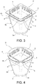
Figures 3 and 4 show, in perspective view, two embodiments of a cup-shaped body included in a capsule or cartridge according to the present invention; -
Figure 5 is a perspective view which shows, in simplified form, part of a machine for the preparation of beverages, for use with capsules according to the present invention; -
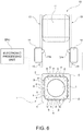
Figure 6 is substantially a plan view from above in the direction of the arrow VI ofFigure 5 ; -
Figure 7 is a perspective view similar to that presented inFigure 5 , and shows a different stage of use of a capsule according to the present invention; -
Figure 8 is a plan view from above in the direction of the arrow VIII ofFigure 7 ; -
Figure 9 is a view similar to that presented inFigure 7 , and shows a subsequent stage of use of a capsule according to the present invention; -
Figure 10 is a plan view from above in the direction of the arrow X ofFigure 9 ; -
Figure 11 is a perspective view similar to that presented inFigure 9 , and shows a further stage of use of a capsule according to the present invention; -
Figure 12 is a plan view from above in the direction of the arrow XII ofFigure 11 ; -
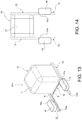
Figure 13 is a view similar to that presented inFigure 11 , and shows the infusion assembly when closed, ready for extraction of the beverage; -
Figure 14 is a plan view from above in the direction of the arrow XIV ofFigure 13 ; and -
Figures 15 and 16 are plan views from below of two different capsules according to the present invention. -
Figures 1 and 2 show (general reference sign 1) a capsule for the preparation of a beverage, in particular espresso coffee, according to the present invention. - The capsule 1 illustrated therein comprises a cup-
shaped body 2, having abottom wall 3, a lateral wall with thegeneral reference sign 4, and a flange-liketop formation 5, which is essentially planar and extends transversely towards the outside. - The capsule 1 further comprises a
cover 6, fixed, for example by heat sealing, to the flange-like formation 5 of thebody 2, in such a way as to define and enclose a chamber 7 (Figures 3 and 4 ) containing a quantity or dose of a material for the preparation of the beverage, for example ground roasted coffee. - With the exception of the embodiment shown in
Figure 4 , the cup-shaped body 2 of a capsule 1 according to the accompanying drawings presents a flange-like formation 5 having an essentially quadrangular outer perimeter. - In the embodiment according to
Figure 4 , the flange-like formation 5 instead has an essentially circular outer perimeter. - In any case, it is appropriate for the
cover 6 to have a shape corresponding to the outer perimeter of theflange 5 of thecapsule body 2 to which it must be fixed. - In the embodiments shown in the drawings, the cup-
shaped body 2 has an essentiallycircular bottom wall 3, with aperipheral edge 3a projecting axially from the side opposite the flange-like formation 5. - Accordingly, the cup-
shaped body 2 has a firstlateral wall portion 4a, the transverse cross-section of which, from thebottom wall 3 in the direction of the flange-like formation 5, passes gradually from an essentially circular shape to an at least approximately quadrangular shape, with preferably rounded vertexes. - The
lateral wall portion 4a of thebody 2 is connected to the flange-like formation 5 by means of asecond wall portion 4b, of essentially prismatic shape, with preferably rounded and externally convex corners. - In proximity to the flange-
like formation 5, the cup-shaped body 2 of the capsules illustrated in the drawings thus has four essentially planar lateral wall portions or faces, formed by thelateral surface portion 4b. - In other embodiments, the cup-
shaped body 2 may have just one essentially planar lateral wall portion or face. - In each planar lateral wall portion or face, the cup-
shaped body 2 has a plurality ofprojections 8 andrecesses 9. - The
projections 8 protrude transversely towards the outside and the number of projections, together with the arrangement thereof, define an identification of the capsule 1. - The
projections 8 and therecesses 9 of each planar face or surface of thebody 2 are mutually aligned in an essentially rectilinear direction, belonging to a plane essentially parallel to the flange-like formation 5. - As can be seen in
Figures 3 and 4 , theprojections 8 are internally hollow and the cavities thereof are in communication with theregion 7 inside the cup-shaped body 2. - The thickness of the walls of the
projections 8, and the material of which the cup-shaped body 2 is made, are such that theprojections 8 may be torn, to allow water and/or steam to enter (also) through thelateral wall 4 in the cup-shaped body 2, substantially in accordance with the solution forming the subject matter of Italian patent applicationTO2011A000478 projections 8 may advantageously be achieved using an infusion assembly according to International applicationWO2013/111088 A1 , also in the name of the same Applicant. - With reference to
Figures 3 and 4 , theprojections 8 are advantageously adjacent the flange-like formation 5, with which they join such that the inner perimeter of the flange-like formation 5 has a corresponding plurality of indentations. - The
projections 8 and therecesses 9 may be detected, for example in the manner described below, and interpreted as elements of a code, such as binary code, that identifies the capsule. Thus, for example, eachprojection 8 may be interpreted as a logical "1", and each recess having a width equal to a predetermined pitch may be interpreted as a logical "0". - The
projections 8 and therecesses 9 may also be attributed other meanings, with a view to creating, and subsequently decoding, the identification of the capsule. - Capsules provided with an identification in the form of projections and recesses according to the invention may be used in machines for the preparation of beverages equipped with appropriate detectors/readers. An example of such devices will be described in detail below.
- In order for it not to matter which way such a capsule is placed in a corresponding machine for the preparation of beverages, the
projections 8 and therecesses 9 associated with two opposite planar surfaces or faces of thebody 2 of the capsule may be specularly symmetrical with respect to an intermediate centre-line, so as to form a corresponding identification/information code which is specularly symmetrical. - Alternatively, the projections and the recesses of at least two parallel planar faces of the
body 2 of the capsule may form an identification/information code containing information that indicates the direction in which the capsule has been placed in the machine, and therefore the direction of "reading" thereof. Thus, for example, the sequence of projections and recesses may contain twoprojections 8 close together at one end, and a (relatively) isolated relief at the other end, in such a way as to allow the "readers" to detect the direction in which the user has placed the capsule in the machine. - Further embodiments of the projections or protrusions, and the associated recesses, will be described below, in particular with reference to
Figures 15 and 16 . - In a capsule according to the invention in which the cup-
shaped body 2 has four essentially planar lateral wall portions or faces, which are parallel each to another one, theprojections 8 and therecesses 9 of each of these lateral wall portions or faces may advantageously form the same identification/information code on each of them. - With reference to
Figures 5 to 14 , an embodiment of a machine for the preparation of beverages and, in particular, the means thereof for detecting or "reading" the identification codes of a capsule 1 according to the present invention will now be described. -
Figures 5 to 14 show, by way of example and in simplified form, only (and partially) the infusion assembly of said machine, said assembly being associated with a device for introduction of a capsule and for reading the identification/information code of the capsule. - In
Figure 5 ,reference sign 10 generally indicates an infusion assembly, of a type known per se, for the preparation of a beverage by extraction under pressure, with the use of a capsule 1 as described above. - The
infusion assembly 10 comprises a first and a second part, 11 and 12, which may be moved with respect to one another, between a relative position of opening, shown inFigure 5 , and a closed position shown inFigure 13 . - In the exemplary embodiment shown, the
part 11 is movable, and has a cavity inside, shown in broken lines inFigure 5 where it is indicated with 11a, which can receive a capsule 1 as described above. - The
part 12 is fixed. The latter, as known per se and not shown, may be provided with means for tearing thecover 6 of the capsule placed in theinfusion assembly 10, and for injecting hot water and/or steam under pressure into the capsule 1, to make the beverage. - The
movable part 11, as likewise known per se and not shown, may be provided with a device for perforating thebottom wall 3 of the capsule 1, and a conduit for dispensing the beverage made into a receiving vessel such as a glass or a cup. - The present invention is not however limited to an embodiment in which the
part 11 is movable and thepart 12 is fixed, but can encompass embodiments in which both parts are movable relative to one another, or in which thepart 11 is fixed and thepart 12 is movable. - The
infusion assembly 10 is associated with a retaining and guiding device, for positioning a capsule or cartridge 1 between the twoparts Figure 5 ). - In the exemplary embodiment shown, said retaining and guiding device comprises two
straight guides 13, parallel to one another, provided withrespective facing grooves 13a which can engage with two opposite sides of the perimeter of the flange-like formation 5 andcover 6 of the capsule 1. - The
guides 13 define a direction of introduction of a capsule 1 in the area between theparts infusion assembly 10, said direction being indicated by the arrow F1 inFigure 5 . This direction is essentially perpendicular to the direction in which the twoparts infusion assembly 10 move towards and away from one another, the direction that is indicated by the double arrow F2 inFigure 5 . - However, it is not imperative that the capsule 1 be introduced with a movement that follows a straight line, orthogonal to the direction of relative movement of the
parts infusion assembly 10 move together/apart in a straight line. - In
Figures 5 and6 , the capsule 1 is shown prior to the insertion of the two sides of the flange-like formation 5 into the grooves orchannels 13a of theguides 13. - In the exemplary embodiment shown, two
microswitches 14 are mounted on theguides 13, said microswitches facing each other in a direction transverse to the direction F1. - The
microswitches 14 are each provided with amovable member 14a for controlling switching, which causes said microswitch to open and close. Thesemembers 14a protrude transversely, in such a way that they may interact with theprojections 8 of two opposite planar faces of theportion 4b of the lateral surface of thebody 2 of the capsule. - Each time a
member 14a passes from arecess 9 to aprojection 8, it causes a switching of the associatedmicroswitch 14, for example in the sense that it causes the microswitch to open and, when it passes from aprojection 8 to arecess 9, it causes reverse switching, for example causing the microswitch to close. - The push-
button control members 14a of themicroswitches 14 thus act as actual feelers, which explore and "read" the sequence ofprojections 8 and recesses 9, or the identification/information code associated with a corresponding planar surface of thebody 2 of the capsule 1 inserted into thegrooves 13a of theguides 13. - As can be seen in
Figure 5 , themicroswitches 14 are arranged along the path followed by the capsule 1 as it goes from a position of initial insertion into theguides 13 to the position (shown inFigure 11 ) in which the capsule 1 is positioned between theparts infusion assembly 10, which are still open. The "reading" of the codes associated with two opposite planar faces of thebody 2 of the capsule 1 thus takes place before the capsule reaches the intermediate position ofFigure 11 , and therefore before the start of infusion proper. -
Figures 7 and 8 show a capsule 1 that has already been inserted a good way into theguides 13, themicroswitches 14 progressively reading theprojections 8 and recesses 9 of two opposite planar faces thereof. -
Figures 9 and 10 show the capsule 1 at a subsequent stage, in which it is beginning to be positioned between the twoparts infusion assembly 10, and themicroswitches 14 are exploring theprojections 8 and therecesses 9 constituting the code. - As shown in
Figure 6 , themicroswitches 14 are connected to an electronic processing unit EPU for detecting the switching of these microswitches, and accordingly acquiring the codes associated with the two explored sides of the capsule 1. - These codes may include information relating to the characteristics of the contents of the capsule, and the optimal conditions for making the beverage by infusion.
- Once the capsule 1 has reached the position shown in
Figure 11 , the twoparts infusion assembly 10 are prompted to move towards one another, until said assembly is in the closed position, as shown inFigures 13 and 14 . - In this position, the capsule 1 is locked inside the infusion chamber defined by the two
parts assembly 10, which firmly clamp the flange-like formation 5 andcover 6 of said capsule. - In a manner known per se, the injection of hot water and/or steam into the capsule, and the extraction of the beverage, which is dispensed into a receiving vessel (not shown), may then be commanded.
- The parameters (for example the flow rate, pressure and temperature of the water injected) may advantageously be determined on the basis of the identification/information code detected by means of the
microswitches 14 and analysed and recognized by the electronic processing unit EPU. - After the beverage has been extracted and dispensed, the
infusion assembly 10 may be reopened, and the used capsule 1 can be removed, in one of several ways known per se. - As soon as the
assembly 10 is open once more as shown inFigures 5 and6 , the machine is ready for the start of a new cycle of beverage preparation, by insertion of a fresh capsule therein. -
Figures 15 and 16 show two capsules 1 according to the present invention, with particular embodiments ofprojections 8 and recesses 9 on two pairs of facing planar faces or surfaces. - In the capsule according to
Figure 15 , each one of a pair of peripherally contiguous planar faces orsurfaces 4c, 4d bearsprojections 8 and recesses 9 that define the same auxiliary reference code ("clock" code), whereas each one of a pair of peripherally contiguous planar faces orsurfaces 4e, 4f bearsprojections 8 and recesses 9 that define the actual identification/information code of the capsule 1. - The auxiliary reference code arranged on
faces 4c and 4d comprises a plurality ofprojections 8, evenly distributed and evenly spaced (by corresponding recesses 9) in the rectilinear direction of alignment thereof. - In the embodiment shown in
Figure 15 , eachprojection 8 on the planar faces orsurfaces 4e, 4f is aligned with acorresponding projection 8 of the auxiliary reference code borne by thefaces 4c, 4d. - In a variant embodiment, the
projections 8 on thefaces 4e, 4f can be staggered relative tocorresponding projections 8 of the auxiliary reference code borne by the planar face or surface opposite. If such an offset or phase shift is not equal to one half-width of arecess 9 on thefaces 4c, 4d, the electronic processing unit EPU can recognize the direction of insertion of the capsule 1 into the machine. Alternatively, the two "readers" 14 of codes carried by two opposite faces of the capsule may be staggered with respect to one another, in the direction F1 of insertion of the capsule 1. - In the embodiment according to
Figure 16 , all the planar faces or surfaces 4c-4f all bear the same distribution ofprojections 8 and recesses 9 which defines the identification/information code associated with the capsule 1. Moreover, this distribution is designed in such a way that the logical addition of the codes of two opposite faces (e.g. faces 4c and 4e, or faces 4d and 4f) corresponds to the auxiliary reference code of thefaces 4c and 4d of the embodiment according toFigure 15 . - With the capsule according to
Figure 16 , the electronic processing unit EPU detects the same code irrespective of the direction of insertion of the capsule in the machine for the preparation of the beverage. Moreover, the code of each face may be used as auxiliary reference code for the code borne by the planar face or surface opposite. - Naturally, many other modes of coding may be used by specialists in the field.
- With the solution according to the present invention, it is possible to create, by means of projections and recesses on the lateral wall of a capsule, relatively well-structured codes capable of conveying more information than could be conveyed by prior art solutions.
- Naturally, without prejudice to the principle of the invention, the forms of embodiment and details thereof may be varied widely with respect to what has been described and illustrated purely by way of non-limiting example, without thereby exceeding the scope of the invention as defined in the following claims.
Claims (23)
- Capsule or cartridge (1) for the preparation of a beverage, in particular espresso coffee, comprising
a cup- shaped body (2) with a bottom wall (3), a lateral wall (4) and a flange-like top formation (5) which extends transversely towards the outside, and
a cover (6) fixed to the flange-like formation (5) of said body (2), such as to define a chamber (7) containing a material for the preparation of the beverage, in particular ground roasted coffee;
wherein the lateral wall (4) of the body (2) has a plurality of projections (8) and recesses (9) which as a whole define at least an identification of the capsule (1);
said projections (8) and recesses (9) being aligned in an essentially rectilinear direction, belonging to a plane essentially parallel to said flange-like formation (5) of the body (2) of the capsule (1);
the capsule or cartridge (1) being characterised in that
said projections (8) are internally hollow and communicate with a region (7) inside the cup- shaped body (2), and are adapted for being torn to allow an introduction of liquid and/or steam through the lateral wall (4) of the cup- shaped body (2). - Capsule or cartridge according to Claim 1, wherein in proximity to the flange-like formation (5) the cup-shaped body (2) has at least one lateral wall portion or face (4c-4f) in which there is provided said plurality of projections (8) and recesses (9).
- Capsule or cartridge according to Claim 2, wherein in proximity to the flange-like formation (5) the cup-shaped body (2) has at least two external lateral wall portions or faces (4c-4f) which are essentially planar and parallel with each other and in which there are provided respective pluralities of projections (8) and recesses (9).
- Capsule or cartridge according to Claim 2 or Claim 3, wherein in proximity to the flange-like formation (5) the cup-shaped body (2) has four external lateral wall portions or faces (4c-4f) which are essentially planar and parallel each to another one, and in which there are provided respective pluralities of projections (8) and recesses (9).
- Capsule or cartridge according to any of the preceding claims, wherein the cup-shaped body (2) has a bottom wall (3) which is essentially circular.
- Capsule or cartridge according to Claims 4 and 5, wherein the cup-shaped body (2) has a first lateral wall portion (4a) whose transverse cross-section, from the bottom wall (3) to the flange-like formation (5), passes gradually from an essentially circular shape to an at least approximately quadrangular shape.
- Capsule or cartridge according to Claim 6, wherein between said first lateral wall portion (4a) and the flange-like formation (5) the cup-shaped body (2) has a second wall portion (4b) which is essentially prismatic, with a transverse cross-section having an essentially quadrangular shape, with preferably rounded and externally convex vertexes, and in which there are provided said lateral planar faces.
- Capsule or cartridge according to any of the preceding claims, wherein the flange-like formation (5) of the cup-shaped body (2) has an external perimeter which is substantially quadrangular.
- Capsule or cartridge according to any of Claims 1 to 7, wherein the flange-like formation (5) of the cup-shaped body (2) has an external perimeter which is essentially circular.
- Capsule or cartridge according to any of the preceding claims, wherein said projections (8) are adjacent the flange-like formation (5), with which they join such that the inner perimeter of the flange-like formation (5) has a corresponding plurality of indentations.
- Capsule or cartridge according to any of the preceding claims, wherein said projections (8) and recesses (9) form an identification/information code which is specularly symmetrical with respect to an intermediate centre-line.
- Capsule or cartridge according to any of Claims 1 to 11, wherein said projections (8) and recesses (9) form an identification/information code containing an information indicative of its reading direction.
- Capsule or cartridge according to Claim 3 or Claim 6, wherein the projections (8) and the recesses (9) provided in one external lateral face (4c, 4d) define an auxiliary reference code adapted for facilitating the reading and the decoding of the projections (8) and the recesses (9) provided in the opposite, parallel wall portion (4e, 4f), which define the identification of the capsule (1).
- Capsule or cartridge according to Claims 4 and 13, wherein each of two planar walls (4c, 4d) which are perimetrally adjacent one another have projections (8) and recesses (9) which define said auxiliary reference code, and each of the other two planar walls or faces (4e, 4f) which are perimetrally adjacent one another has projections (8) and recesses (9) which define the identification code of the capsule (1).
- Capsule or cartridge according to Claim 13 or Claim 14, wherein said auxiliary reference code comprises a plurality of projections (8) and recesses (9) which are regularly spaced along their rectilinear direction of alignment.
- Capsule or cartridge according to any of Claims 13 to 15, wherein projections (8) which define an identification code have a same predetermined staggering, possibly null, with respect to corresponding projections (8) of the auxiliary reference code.
- Capsule or cartridge according to Claim 4, wherein said lateral wall portions or faces (4c-4f) have projections (8) and recesses (9) which define, on each of them, a same identification/information code.
- Infusion assembly (10) for a machine for the preparation of a beverage, in particular espresso coffee, using a capsule or cartridge (1) containing a substance for the preparation of the beverage, in particular ground roasted coffee, comprising- a first part and a second part (11, 12) adapted to be displaced one with respect to the other between a relative opening position in which they allow a capsule or cartridge (1) to be interposed therebetween, and a relative closing position in which they jointly define an infusion chamber in which said capsule or cartridge (1) is enclosed, and- retaining and guiding means (13) adapted to allow a guided displacement of a capsule or cartridge (1) from an introduction position to an intermediate position in which said capsule or cartridge extends between said first and second parts (11, 12) when the latter are in their relative position of opening;the assembly (10) being characterized by comprising detection or reading means (14) adapted to detect or read the identification of the capsule (1) defined by said at least one plurality of projections (8) and recesses (9) of a capsule or cartridge (1) according to one or more of the preceding claims, during the passage thereof from said introduction position to said intermediate position.
- Infusion assembly according to Claim 18, wherein the detection or reading means are of optical or mechanical kind.
- Infusion assembly according to Claim 19, for use with capsules or cartridges according to Claim 7, wherein the detection or reading means (14) comprise at least one electric microswitch (14) provided with a movable member (14a) controlling the switching thereof, adapted to cause the opening and the closing thereof, said microswitch (14) being disposed adjacent the retaining and guiding means (13) such that the movable member (14a) thereof is adapted to explore, like a feeler member, said at least one plurality of projections (8) and recesses (9), and to cause a switching of the microswitch at each transition from a projection (8) to a recess (9), and from a recess (9) to a projection (8).
- Infusion assembly according to Claim 19, for use with capsules or cartridges (1) according to Claim 3 or Claim 4, wherein the detection or reading means comprise a pair of microswitches (14) disposed essentially one opposite the other in a direction transverse to the displacement direction (F1) of a capsule or cartridge (1), along said retaining and guiding means (13), and each adapted to feel a respective plurality of projections (8) and recesses (9) of the body (2) of the capsule or cartridge (1).
- Infusion assembly according to Claim 19, for use with capsules or cartridges according to Claim 7, wherein the detection or reading means (14) comprise at least one optical reading device adapted to scan said at least one plurality of projections (8) and recesses (9) and to provide an electric signal which has a commutation in correspondence of each transition from a projection (8) to a recess (9), and from a recess (9) to a projection (8).
- Infusion assembly according to Claim 19, for use with capsules or cartridges (1) according to Claim 3 or Claim 4, wherein the detection or reading means comprise a pair of optical readers disposed essentially opposite one another in a direction transverse to the direction of displacement (F1) of a capsule or cartridge (1) along said retaining and guiding means (13), and adapted each to explore or scan a respective plurality of projections (8) and recesses (9) of the body (2) of the capsule or cartridge (1).
Applications Claiming Priority (2)
| Application Number | Priority Date | Filing Date | Title |
|---|---|---|---|
| IT001076A ITTO20121076A1 (en) | 2012-12-14 | 2012-12-14 | CAPSULE OR POD AND INFUSION GROUP FOR THE PREPARATION OF A BEVERAGE, IN PARTICULAR COFFEE |
| PCT/IB2013/060848 WO2014091439A1 (en) | 2012-12-14 | 2013-12-12 | Capsule or cartridge and infusion assembly for the preparation of a beverage, in particular coffee |
Publications (2)
| Publication Number | Publication Date |
|---|---|
| EP2931091A1 EP2931091A1 (en) | 2015-10-21 |
| EP2931091B1 true EP2931091B1 (en) | 2017-08-23 |
Family
ID=47683946
Family Applications (1)
| Application Number | Title | Priority Date | Filing Date |
|---|---|---|---|
| EP13826950.1A Active EP2931091B1 (en) | 2012-12-14 | 2013-12-12 | Capsule or cartridge and infusion assembly for the preparation of a beverage, in particular coffee |
Country Status (7)
| Country | Link |
|---|---|
| US (2) | US20150297021A1 (en) |
| EP (1) | EP2931091B1 (en) |
| CN (1) | CN104883937B (en) |
| AU (1) | AU2013356874B2 (en) |
| CA (1) | CA2889153C (en) |
| IT (1) | ITTO20121076A1 (en) |
| WO (1) | WO2014091439A1 (en) |
Families Citing this family (43)
| Publication number | Priority date | Publication date | Assignee | Title |
|---|---|---|---|---|
| US10722066B2 (en) * | 2010-12-04 | 2020-07-28 | Adrian Rivera | Windowed single serving brewing material holder |
| US11832755B2 (en) * | 2007-07-13 | 2023-12-05 | Adrian Rivera | Brewing material container for a beverage brewer |
| US10071851B2 (en) | 2010-07-12 | 2018-09-11 | Robert Bao Vu | Apparatus and products for producing beverages, and methods for making and using same |
| DK3521209T3 (en) | 2010-07-22 | 2020-04-27 | K Fee System Gmbh | BOTTLE COOKING COVER |
| DE102012105282A1 (en) | 2012-06-18 | 2013-12-19 | K-Fee System Gmbh | Portion capsule and method of making a beverage with a portion capsule |
| DE102012223291A1 (en) | 2012-12-14 | 2014-06-18 | K-Fee System Gmbh | Portion capsule and method of making a beverage with a portion capsule |
| ITTO20121076A1 (en) * | 2012-12-14 | 2014-06-15 | Lavazza Luigi Spa | CAPSULE OR POD AND INFUSION GROUP FOR THE PREPARATION OF A BEVERAGE, IN PARTICULAR COFFEE |
| BR202014018463U2 (en) * | 2014-07-28 | 2016-03-29 | Blend Máquinas E Bebidas S A B | constructive arrangement introduced into a baby drinker |
| MX2017010659A (en) | 2015-02-27 | 2017-11-16 | K Fee System Gmbh | Single serve capsule comprising a filter element connected thereto by sealing. |
| PT3307647T (en) | 2015-06-10 | 2019-10-28 | K Fee System Gmbh | Capsule with a three layer fleece |
| KR20180030626A (en) | 2015-07-13 | 2018-03-23 | 카-페 시스템 게엠베하 | Filter element with cutout |
| EP3350101B1 (en) | 2015-09-18 | 2019-10-30 | K-fee System GmbH | Adapter for a single serve capsule |
| ES2939370T3 (en) * | 2016-01-12 | 2023-04-21 | Freezio Ag | Dispensing system with cartridge holder |
| GB2550106B (en) | 2016-03-24 | 2018-08-29 | Cambdev Ltd | Coffee brewing system |
| CN110769726A (en) * | 2017-05-03 | 2020-02-07 | 雀巢产品有限公司 | Method for preparing tea |
| GB201708215D0 (en) | 2017-05-23 | 2017-07-05 | Cambdev Ltd | Apparatus for preparing herbal infusions |
| GB201715365D0 (en) | 2017-09-22 | 2017-11-08 | Cambdev Ltd | Coffee brewing apparatus |
| GB201719683D0 (en) | 2017-11-27 | 2018-01-10 | Cambdev Ltd | Improved extraction sleeve coffee infusion |
| GB201719682D0 (en) | 2017-11-27 | 2018-01-10 | Cambdev Ltd | Improved extraction sleeve coffee brewing apparatus |
| GB201719687D0 (en) | 2017-11-27 | 2018-01-10 | Cambdev Ltd | Extraction sleeve coffee making apparatus |
| KR102491513B1 (en) | 2018-07-27 | 2023-01-27 | 지씨에스 게르만 캡슐 솔루션 게엠베하 | A method for preparing a portion capsule for preparing a beverage in a beverage making machine, a portion capsule, and a method for preparing a beverage with a beverage making machine and a portion capsule |
| US12459728B2 (en) | 2018-11-22 | 2025-11-04 | Gcs German Capsule Solution Gmbh | Seal for a single serve capsule |
| IT201900004847A1 (en) * | 2019-04-01 | 2020-10-01 | Essse Caffe S P A | CAPSULE FOR INFUSION PRODUCTS |
| EP3957579A1 (en) * | 2020-08-19 | 2022-02-23 | Tchibo GmbH | Portion capsule base body and portion capsule for a beverage preparation machine and corresponding method |
| US11805934B1 (en) * | 2020-10-21 | 2023-11-07 | Adrian Rivera | Brewing material lid and container for a beverage brewer |
| EP4377228B1 (en) * | 2021-07-30 | 2025-09-10 | K-fee System GmbH | Capsule for the preparation of beverages |
| WO2023111885A1 (en) * | 2021-12-17 | 2023-06-22 | Gise Caffe' S.R.L. | Machine for preparing and extracting a hot beverage |
| US12213617B2 (en) | 2022-05-13 | 2025-02-04 | Sharkninja Operating Llc | Flavored beverage carbonation process |
| US11647860B1 (en) | 2022-05-13 | 2023-05-16 | Sharkninja Operating Llc | Flavored beverage carbonation system |
| US11751585B1 (en) | 2022-05-13 | 2023-09-12 | Sharkninja Operating Llc | Flavored beverage carbonation system |
| US12096880B2 (en) | 2022-05-13 | 2024-09-24 | Sharkninja Operating Llc | Flavorant for beverage carbonation system |
| US12539500B2 (en) | 2022-08-31 | 2026-02-03 | Sharkninja Operating Llc | Additive containers |
| US12103840B2 (en) | 2022-11-17 | 2024-10-01 | Sharkninja Operating Llc | Ingredient container with sealing valve |
| US12084334B2 (en) | 2022-11-17 | 2024-09-10 | Sharkninja Operating Llc | Ingredient container |
| US11745996B1 (en) | 2022-11-17 | 2023-09-05 | Sharkninja Operating Llc | Ingredient containers for use with beverage dispensers |
| US11634314B1 (en) | 2022-11-17 | 2023-04-25 | Sharkninja Operating Llc | Dosing accuracy |
| US11738988B1 (en) | 2022-11-17 | 2023-08-29 | Sharkninja Operating Llc | Ingredient container valve control |
| USD1092208S1 (en) | 2022-12-23 | 2025-09-09 | Sharkninja Operating Llc | Cap of ingredient container |
| USD1091308S1 (en) | 2022-12-23 | 2025-09-02 | Sharkninja Operating Llc | Ingredient container |
| US11871867B1 (en) | 2023-03-22 | 2024-01-16 | Sharkninja Operating Llc | Additive container with bottom cover |
| US12116257B1 (en) | 2023-03-22 | 2024-10-15 | Sharkninja Operating Llc | Adapter for beverage dispenser |
| US11925287B1 (en) | 2023-03-22 | 2024-03-12 | Sharkninja Operating Llc | Additive container with inlet tube |
| US12005408B1 (en) | 2023-04-14 | 2024-06-11 | Sharkninja Operating Llc | Mixing funnel |
Family Cites Families (19)
| Publication number | Priority date | Publication date | Assignee | Title |
|---|---|---|---|---|
| US2832523A (en) * | 1954-05-28 | 1958-04-29 | Jagenberg Werke Ag | Liquid-tight containers of paper, cardboard or the like carton-forming materials |
| US3095801A (en) | 1960-09-19 | 1963-07-02 | Charles R Fogg | Beverage percolating apparatus with unit dry beverage container |
| US3309980A (en) | 1964-03-03 | 1967-03-21 | Continental Can Co | Disposable coffee container |
| US3917157A (en) * | 1974-02-07 | 1975-11-04 | Phillips Petroleum Co | Stackable container and cover |
| US5243164A (en) * | 1990-12-14 | 1993-09-07 | Gee Associates | Beverage maker |
| IT1256690B (en) | 1992-03-04 | 1995-12-12 | Lavazza Luigi Spa | DISPOSABLE CAPSULE FOR USE IN THE MACHINES FOR THE EXTRACTION AND DISTRIBUTION OF HOT DRINKS. |
| DE102004002005A1 (en) | 2004-01-14 | 2005-08-11 | Schifferle, René | Portion capsule with ground coffee for making a coffee beverage |
| ITRM20060227A1 (en) * | 2006-04-24 | 2007-10-25 | Cafe Do Brasil S P A | SINGLE-DOSE CAPSULES CONTAINING A BEVERAGE PREPARATION |
| ITBO20060566A1 (en) | 2006-07-28 | 2008-01-29 | Grimac S R L | METHOD AND DEVICE FOR CONTROL OF THE DELIVERY OF AN INFUSION PRODUCT FOR A DISPENSER MACHINE |
| DK1886942T3 (en) | 2006-08-04 | 2010-03-29 | Lavazza Luigi Spa | Sealed capsule for making a beverage, especially espresso coffee |
| IT1399364B1 (en) * | 2010-04-07 | 2013-04-16 | Technology For Beverage Srl | DISPOSABLE CAPSULE FOR THE PRODUCTION OF AN AROMATIC DRINK, PROCEDURE AND PROCESSING MACHINE FOR ITS REALIZATION |
| DK3521209T3 (en) * | 2010-07-22 | 2020-04-27 | K Fee System Gmbh | BOTTLE COOKING COVER |
| DE102011010534A1 (en) * | 2011-02-07 | 2012-08-09 | K-Fee System Gmbh | Portion capsule for producing hot coffee in coffee vending machine, has cavity closed by membrane, and identifier e.g. radio frequency identification code, is provided in membrane for individualizing respective portion capsule |
| DE102010044249A1 (en) * | 2010-09-02 | 2012-03-08 | Eugster/Frismag Ag | Brewing device with a capsule recognition |
| ITTO20110478A1 (en) | 2011-05-31 | 2012-12-01 | Lavazza Luigi Spa | CAPSULE, MACHINE, SYSTEM AND PROCEDURE FOR THE PREPARATION OF DRINKS, ESPECIALLY COFFEE |
| ITTO20120061A1 (en) | 2012-01-25 | 2013-07-26 | Lavazza Luigi Spa | SYSTEM AND MACHINE FOR THE PREPARATION OF DRINKS WITH THE USE OF CAPSULES |
| US20150158665A1 (en) * | 2012-06-29 | 2015-06-11 | K-Fee System Gmbh | Portion capsule comprising a plastic film provided with a machine-detectable identification |
| ITTO20121076A1 (en) * | 2012-12-14 | 2014-06-15 | Lavazza Luigi Spa | CAPSULE OR POD AND INFUSION GROUP FOR THE PREPARATION OF A BEVERAGE, IN PARTICULAR COFFEE |
| RU2639093C1 (en) * | 2013-12-31 | 2017-12-19 | Конинклейке Филипс Н.В. | Machine for beverages preparation |
-
2012
- 2012-12-14 IT IT001076A patent/ITTO20121076A1/en unknown
-
2013
- 2013-12-12 US US14/439,138 patent/US20150297021A1/en not_active Abandoned
- 2013-12-12 CA CA2889153A patent/CA2889153C/en active Active
- 2013-12-12 CN CN201380064668.6A patent/CN104883937B/en active Active
- 2013-12-12 WO PCT/IB2013/060848 patent/WO2014091439A1/en not_active Ceased
- 2013-12-12 AU AU2013356874A patent/AU2013356874B2/en active Active
- 2013-12-12 EP EP13826950.1A patent/EP2931091B1/en active Active
-
2017
- 2017-07-24 US US15/657,409 patent/US10743707B2/en active Active
Non-Patent Citations (1)
| Title |
|---|
| None * |
Also Published As
| Publication number | Publication date |
|---|---|
| CN104883937A (en) | 2015-09-02 |
| CA2889153C (en) | 2021-02-23 |
| US20150297021A1 (en) | 2015-10-22 |
| WO2014091439A1 (en) | 2014-06-19 |
| US20170319003A1 (en) | 2017-11-09 |
| AU2013356874B2 (en) | 2018-08-09 |
| EP2931091A1 (en) | 2015-10-21 |
| ITTO20121076A1 (en) | 2014-06-15 |
| US10743707B2 (en) | 2020-08-18 |
| CA2889153A1 (en) | 2014-06-19 |
| AU2013356874A1 (en) | 2015-05-14 |
| CN104883937B (en) | 2018-11-20 |
Similar Documents
| Publication | Publication Date | Title |
|---|---|---|
| US10743707B2 (en) | Capsule or cartridge and infusion assembly for the preparation of a beverage, in particular coffee | |
| EP2975980B1 (en) | Capsule provided with a code and automated beverage preparation system | |
| RU2672828C2 (en) | Treatment unit of the capsule of the device for preparation of beverages | |
| EP2448843B1 (en) | Capsule for the preparation of a beverage comprising an identification element and beverage preparation device therefor | |
| EP2888181B1 (en) | Capsule assemblies with data storage and communication means | |
| KR20190041036A (en) | Single-serve capsule for making a beverage | |
| CA2766209A1 (en) | Capsule for the preparation of a beverage embedding an identification element | |
| EA027167B1 (en) | Package recognition system | |
| CA2801183A1 (en) | Programming connector for beverage capsules, beverage capsules and kit of capsules and programming connectors | |
| EP3018075B1 (en) | Capsule, beverage preparation system comprising said capsule, and method for operating said system | |
| CN110121469B (en) | Capsule, edible product preparation system | |
| AU2016263818B2 (en) | Portion pack for preparing beverages | |
| CN110139810B (en) | Capsule with improved sealing | |
| CN212606933U (en) | Capsule for infusion products | |
| CN110139811B (en) | Capsule with hermetic retention and edible product preparation system based thereon | |
| HK1170461B (en) | Capsule for the preparation of a beverage comprising an identification element and beverage preparation device therefor |
Legal Events
| Date | Code | Title | Description |
|---|---|---|---|
| PUAI | Public reference made under article 153(3) epc to a published international application that has entered the european phase |
Free format text: ORIGINAL CODE: 0009012 |
|
| 17P | Request for examination filed |
Effective date: 20150420 |
|
| AK | Designated contracting states |
Kind code of ref document: A1 Designated state(s): AL AT BE BG CH CY CZ DE DK EE ES FI FR GB GR HR HU IE IS IT LI LT LU LV MC MK MT NL NO PL PT RO RS SE SI SK SM TR |
|
| AX | Request for extension of the european patent |
Extension state: BA ME |
|
| DAX | Request for extension of the european patent (deleted) | ||
| RIN1 | Information on inventor provided before grant (corrected) |
Inventor name: BUGNANO, LUCA Inventor name: BOLOGNESE, DANILO Inventor name: ROTTA, DENIS Inventor name: CABILLI, ALBERTO |
|
| 17Q | First examination report despatched |
Effective date: 20160714 |
|
| GRAP | Despatch of communication of intention to grant a patent |
Free format text: ORIGINAL CODE: EPIDOSNIGR1 |
|
| INTG | Intention to grant announced |
Effective date: 20170308 |
|
| GRAS | Grant fee paid |
Free format text: ORIGINAL CODE: EPIDOSNIGR3 |
|
| GRAA | (expected) grant |
Free format text: ORIGINAL CODE: 0009210 |
|
| AK | Designated contracting states |
Kind code of ref document: B1 Designated state(s): AL AT BE BG CH CY CZ DE DK EE ES FI FR GB GR HR HU IE IS IT LI LT LU LV MC MK MT NL NO PL PT RO RS SE SI SK SM TR |
|
| REG | Reference to a national code |
Ref country code: GB Ref legal event code: FG4D |
|
| REG | Reference to a national code |
Ref country code: CH Ref legal event code: EP |
|
| REG | Reference to a national code |
Ref country code: AT Ref legal event code: REF Ref document number: 920365 Country of ref document: AT Kind code of ref document: T Effective date: 20170915 |
|
| REG | Reference to a national code |
Ref country code: IE Ref legal event code: FG4D |
|
| REG | Reference to a national code |
Ref country code: DE Ref legal event code: R096 Ref document number: 602013025597 Country of ref document: DE |
|
| RAP2 | Party data changed (patent owner data changed or rights of a patent transferred) |
Owner name: LUIGI LAVAZZA S.P.A. |
|
| REG | Reference to a national code |
Ref country code: NL Ref legal event code: MP Effective date: 20170823 |
|
| REG | Reference to a national code |
Ref country code: FR Ref legal event code: PLFP Year of fee payment: 5 |
|
| REG | Reference to a national code |
Ref country code: LT Ref legal event code: MG4D |
|
| REG | Reference to a national code |
Ref country code: AT Ref legal event code: MK05 Ref document number: 920365 Country of ref document: AT Kind code of ref document: T Effective date: 20170823 |
|
| PG25 | Lapsed in a contracting state [announced via postgrant information from national office to epo] |
Ref country code: FI Free format text: LAPSE BECAUSE OF FAILURE TO SUBMIT A TRANSLATION OF THE DESCRIPTION OR TO PAY THE FEE WITHIN THE PRESCRIBED TIME-LIMIT Effective date: 20170823 Ref country code: LT Free format text: LAPSE BECAUSE OF FAILURE TO SUBMIT A TRANSLATION OF THE DESCRIPTION OR TO PAY THE FEE WITHIN THE PRESCRIBED TIME-LIMIT Effective date: 20170823 Ref country code: HR Free format text: LAPSE BECAUSE OF FAILURE TO SUBMIT A TRANSLATION OF THE DESCRIPTION OR TO PAY THE FEE WITHIN THE PRESCRIBED TIME-LIMIT Effective date: 20170823 Ref country code: SE Free format text: LAPSE BECAUSE OF FAILURE TO SUBMIT A TRANSLATION OF THE DESCRIPTION OR TO PAY THE FEE WITHIN THE PRESCRIBED TIME-LIMIT Effective date: 20170823 Ref country code: AT Free format text: LAPSE BECAUSE OF FAILURE TO SUBMIT A TRANSLATION OF THE DESCRIPTION OR TO PAY THE FEE WITHIN THE PRESCRIBED TIME-LIMIT Effective date: 20170823 Ref country code: NL Free format text: LAPSE BECAUSE OF FAILURE TO SUBMIT A TRANSLATION OF THE DESCRIPTION OR TO PAY THE FEE WITHIN THE PRESCRIBED TIME-LIMIT Effective date: 20170823 Ref country code: NO Free format text: LAPSE BECAUSE OF FAILURE TO SUBMIT A TRANSLATION OF THE DESCRIPTION OR TO PAY THE FEE WITHIN THE PRESCRIBED TIME-LIMIT Effective date: 20171123 |
|
| PG25 | Lapsed in a contracting state [announced via postgrant information from national office to epo] |
Ref country code: IS Free format text: LAPSE BECAUSE OF FAILURE TO SUBMIT A TRANSLATION OF THE DESCRIPTION OR TO PAY THE FEE WITHIN THE PRESCRIBED TIME-LIMIT Effective date: 20171223 Ref country code: GR Free format text: LAPSE BECAUSE OF FAILURE TO SUBMIT A TRANSLATION OF THE DESCRIPTION OR TO PAY THE FEE WITHIN THE PRESCRIBED TIME-LIMIT Effective date: 20171124 Ref country code: LV Free format text: LAPSE BECAUSE OF FAILURE TO SUBMIT A TRANSLATION OF THE DESCRIPTION OR TO PAY THE FEE WITHIN THE PRESCRIBED TIME-LIMIT Effective date: 20170823 Ref country code: PL Free format text: LAPSE BECAUSE OF FAILURE TO SUBMIT A TRANSLATION OF THE DESCRIPTION OR TO PAY THE FEE WITHIN THE PRESCRIBED TIME-LIMIT Effective date: 20170823 Ref country code: BG Free format text: LAPSE BECAUSE OF FAILURE TO SUBMIT A TRANSLATION OF THE DESCRIPTION OR TO PAY THE FEE WITHIN THE PRESCRIBED TIME-LIMIT Effective date: 20171123 Ref country code: ES Free format text: LAPSE BECAUSE OF FAILURE TO SUBMIT A TRANSLATION OF THE DESCRIPTION OR TO PAY THE FEE WITHIN THE PRESCRIBED TIME-LIMIT Effective date: 20170823 Ref country code: RS Free format text: LAPSE BECAUSE OF FAILURE TO SUBMIT A TRANSLATION OF THE DESCRIPTION OR TO PAY THE FEE WITHIN THE PRESCRIBED TIME-LIMIT Effective date: 20170823 |
|
| PG25 | Lapsed in a contracting state [announced via postgrant information from national office to epo] |
Ref country code: DK Free format text: LAPSE BECAUSE OF FAILURE TO SUBMIT A TRANSLATION OF THE DESCRIPTION OR TO PAY THE FEE WITHIN THE PRESCRIBED TIME-LIMIT Effective date: 20170823 Ref country code: RO Free format text: LAPSE BECAUSE OF FAILURE TO SUBMIT A TRANSLATION OF THE DESCRIPTION OR TO PAY THE FEE WITHIN THE PRESCRIBED TIME-LIMIT Effective date: 20170823 Ref country code: CZ Free format text: LAPSE BECAUSE OF FAILURE TO SUBMIT A TRANSLATION OF THE DESCRIPTION OR TO PAY THE FEE WITHIN THE PRESCRIBED TIME-LIMIT Effective date: 20170823 |
|
| REG | Reference to a national code |
Ref country code: DE Ref legal event code: R097 Ref document number: 602013025597 Country of ref document: DE |
|
| PG25 | Lapsed in a contracting state [announced via postgrant information from national office to epo] |
Ref country code: SK Free format text: LAPSE BECAUSE OF FAILURE TO SUBMIT A TRANSLATION OF THE DESCRIPTION OR TO PAY THE FEE WITHIN THE PRESCRIBED TIME-LIMIT Effective date: 20170823 Ref country code: EE Free format text: LAPSE BECAUSE OF FAILURE TO SUBMIT A TRANSLATION OF THE DESCRIPTION OR TO PAY THE FEE WITHIN THE PRESCRIBED TIME-LIMIT Effective date: 20170823 Ref country code: SM Free format text: LAPSE BECAUSE OF FAILURE TO SUBMIT A TRANSLATION OF THE DESCRIPTION OR TO PAY THE FEE WITHIN THE PRESCRIBED TIME-LIMIT Effective date: 20170823 |
|
| PLBE | No opposition filed within time limit |
Free format text: ORIGINAL CODE: 0009261 |
|
| STAA | Information on the status of an ep patent application or granted ep patent |
Free format text: STATUS: NO OPPOSITION FILED WITHIN TIME LIMIT |
|
| REG | Reference to a national code |
Ref country code: CH Ref legal event code: PL |
|
| 26N | No opposition filed |
Effective date: 20180524 |
|
| PG25 | Lapsed in a contracting state [announced via postgrant information from national office to epo] |
Ref country code: SI Free format text: LAPSE BECAUSE OF FAILURE TO SUBMIT A TRANSLATION OF THE DESCRIPTION OR TO PAY THE FEE WITHIN THE PRESCRIBED TIME-LIMIT Effective date: 20170823 |
|
| REG | Reference to a national code |
Ref country code: IE Ref legal event code: MM4A |
|
| PG25 | Lapsed in a contracting state [announced via postgrant information from national office to epo] |
Ref country code: LU Free format text: LAPSE BECAUSE OF NON-PAYMENT OF DUE FEES Effective date: 20171212 Ref country code: MT Free format text: LAPSE BECAUSE OF NON-PAYMENT OF DUE FEES Effective date: 20171212 |
|
| REG | Reference to a national code |
Ref country code: BE Ref legal event code: MM Effective date: 20171231 |
|
| PG25 | Lapsed in a contracting state [announced via postgrant information from national office to epo] |
Ref country code: IE Free format text: LAPSE BECAUSE OF NON-PAYMENT OF DUE FEES Effective date: 20171212 |
|
| PG25 | Lapsed in a contracting state [announced via postgrant information from national office to epo] |
Ref country code: CH Free format text: LAPSE BECAUSE OF NON-PAYMENT OF DUE FEES Effective date: 20171231 Ref country code: BE Free format text: LAPSE BECAUSE OF NON-PAYMENT OF DUE FEES Effective date: 20171231 Ref country code: LI Free format text: LAPSE BECAUSE OF NON-PAYMENT OF DUE FEES Effective date: 20171231 |
|
| PG25 | Lapsed in a contracting state [announced via postgrant information from national office to epo] |
Ref country code: MC Free format text: LAPSE BECAUSE OF FAILURE TO SUBMIT A TRANSLATION OF THE DESCRIPTION OR TO PAY THE FEE WITHIN THE PRESCRIBED TIME-LIMIT Effective date: 20170823 Ref country code: HU Free format text: LAPSE BECAUSE OF FAILURE TO SUBMIT A TRANSLATION OF THE DESCRIPTION OR TO PAY THE FEE WITHIN THE PRESCRIBED TIME-LIMIT; INVALID AB INITIO Effective date: 20131212 |
|
| PG25 | Lapsed in a contracting state [announced via postgrant information from national office to epo] |
Ref country code: CY Free format text: LAPSE BECAUSE OF FAILURE TO SUBMIT A TRANSLATION OF THE DESCRIPTION OR TO PAY THE FEE WITHIN THE PRESCRIBED TIME-LIMIT Effective date: 20170823 |
|
| PG25 | Lapsed in a contracting state [announced via postgrant information from national office to epo] |
Ref country code: MK Free format text: LAPSE BECAUSE OF FAILURE TO SUBMIT A TRANSLATION OF THE DESCRIPTION OR TO PAY THE FEE WITHIN THE PRESCRIBED TIME-LIMIT Effective date: 20170823 |
|
| PG25 | Lapsed in a contracting state [announced via postgrant information from national office to epo] |
Ref country code: TR Free format text: LAPSE BECAUSE OF FAILURE TO SUBMIT A TRANSLATION OF THE DESCRIPTION OR TO PAY THE FEE WITHIN THE PRESCRIBED TIME-LIMIT Effective date: 20170823 |
|
| PG25 | Lapsed in a contracting state [announced via postgrant information from national office to epo] |
Ref country code: PT Free format text: LAPSE BECAUSE OF FAILURE TO SUBMIT A TRANSLATION OF THE DESCRIPTION OR TO PAY THE FEE WITHIN THE PRESCRIBED TIME-LIMIT Effective date: 20170823 |
|
| PG25 | Lapsed in a contracting state [announced via postgrant information from national office to epo] |
Ref country code: AL Free format text: LAPSE BECAUSE OF FAILURE TO SUBMIT A TRANSLATION OF THE DESCRIPTION OR TO PAY THE FEE WITHIN THE PRESCRIBED TIME-LIMIT Effective date: 20170823 |
|
| P01 | Opt-out of the competence of the unified patent court (upc) registered |
Effective date: 20230601 |
|
| PGFP | Annual fee paid to national office [announced via postgrant information from national office to epo] |
Ref country code: GB Payment date: 20251218 Year of fee payment: 13 |
|
| PGFP | Annual fee paid to national office [announced via postgrant information from national office to epo] |
Ref country code: FR Payment date: 20251218 Year of fee payment: 13 |
|
| PGFP | Annual fee paid to national office [announced via postgrant information from national office to epo] |
Ref country code: DE Payment date: 20251222 Year of fee payment: 13 |
|
| PGFP | Annual fee paid to national office [announced via postgrant information from national office to epo] |
Ref country code: IT Payment date: 20251231 Year of fee payment: 13 |