EP2930895A1 - Traffic control method for near-field communication software stack logic link layer - Google Patents
Traffic control method for near-field communication software stack logic link layer Download PDFInfo
- Publication number
- EP2930895A1 EP2930895A1 EP13859956.8A EP13859956A EP2930895A1 EP 2930895 A1 EP2930895 A1 EP 2930895A1 EP 13859956 A EP13859956 A EP 13859956A EP 2930895 A1 EP2930895 A1 EP 2930895A1
- Authority
- EP
- European Patent Office
- Prior art keywords
- data frame
- receive window
- window
- serial number
- size
- Prior art date
- Legal status (The legal status is an assumption and is not a legal conclusion. Google has not performed a legal analysis and makes no representation as to the accuracy of the status listed.)
- Granted
Links
Images

Classifications
-
- H—ELECTRICITY
- H04—ELECTRIC COMMUNICATION TECHNIQUE
- H04L—TRANSMISSION OF DIGITAL INFORMATION, e.g. TELEGRAPHIC COMMUNICATION
- H04L1/00—Arrangements for detecting or preventing errors in the information received
- H04L1/12—Arrangements for detecting or preventing errors in the information received by using return channel
- H04L1/16—Arrangements for detecting or preventing errors in the information received by using return channel in which the return channel carries supervisory signals, e.g. repetition request signals
- H04L1/18—Automatic repetition systems, e.g. Van Duuren systems
- H04L1/1825—Adaptation of specific ARQ protocol parameters according to transmission conditions
-
- H—ELECTRICITY
- H04—ELECTRIC COMMUNICATION TECHNIQUE
- H04B—TRANSMISSION
- H04B5/00—Near-field transmission systems, e.g. inductive or capacitive transmission systems
- H04B5/20—Near-field transmission systems, e.g. inductive or capacitive transmission systems characterised by the transmission technique; characterised by the transmission medium
-
- H—ELECTRICITY
- H04—ELECTRIC COMMUNICATION TECHNIQUE
- H04L—TRANSMISSION OF DIGITAL INFORMATION, e.g. TELEGRAPHIC COMMUNICATION
- H04L1/00—Arrangements for detecting or preventing errors in the information received
- H04L1/12—Arrangements for detecting or preventing errors in the information received by using return channel
- H04L1/16—Arrangements for detecting or preventing errors in the information received by using return channel in which the return channel carries supervisory signals, e.g. repetition request signals
- H04L1/18—Automatic repetition systems, e.g. Van Duuren systems
- H04L1/1809—Selective-repeat protocols
-
- H—ELECTRICITY
- H04—ELECTRIC COMMUNICATION TECHNIQUE
- H04L—TRANSMISSION OF DIGITAL INFORMATION, e.g. TELEGRAPHIC COMMUNICATION
- H04L1/00—Arrangements for detecting or preventing errors in the information received
- H04L1/12—Arrangements for detecting or preventing errors in the information received by using return channel
- H04L1/16—Arrangements for detecting or preventing errors in the information received by using return channel in which the return channel carries supervisory signals, e.g. repetition request signals
- H04L1/18—Automatic repetition systems, e.g. Van Duuren systems
- H04L1/1829—Arrangements specially adapted for the receiver end
- H04L1/1832—Details of sliding window management
-
- H—ELECTRICITY
- H04—ELECTRIC COMMUNICATION TECHNIQUE
- H04L—TRANSMISSION OF DIGITAL INFORMATION, e.g. TELEGRAPHIC COMMUNICATION
- H04L1/00—Arrangements for detecting or preventing errors in the information received
- H04L1/12—Arrangements for detecting or preventing errors in the information received by using return channel
- H04L1/16—Arrangements for detecting or preventing errors in the information received by using return channel in which the return channel carries supervisory signals, e.g. repetition request signals
- H04L1/18—Automatic repetition systems, e.g. Van Duuren systems
- H04L1/1829—Arrangements specially adapted for the receiver end
- H04L1/1835—Buffer management
-
- H—ELECTRICITY
- H04—ELECTRIC COMMUNICATION TECHNIQUE
- H04W—WIRELESS COMMUNICATION NETWORKS
- H04W4/00—Services specially adapted for wireless communication networks; Facilities therefor
- H04W4/80—Services using short range communication, e.g. near-field communication [NFC], radio-frequency identification [RFID] or low energy communication
-
- H—ELECTRICITY
- H04—ELECTRIC COMMUNICATION TECHNIQUE
- H04W—WIRELESS COMMUNICATION NETWORKS
- H04W72/00—Local resource management
- H04W72/04—Wireless resource allocation
- H04W72/044—Wireless resource allocation based on the type of the allocated resource
- H04W72/0446—Resources in time domain, e.g. slots or frames
-
- H—ELECTRICITY
- H04—ELECTRIC COMMUNICATION TECHNIQUE
- H04L—TRANSMISSION OF DIGITAL INFORMATION, e.g. TELEGRAPHIC COMMUNICATION
- H04L47/00—Traffic control in data switching networks
- H04L47/10—Flow control; Congestion control
- H04L47/27—Evaluation or update of window size, e.g. using information derived from acknowledged [ACK] packets
Definitions
- the present invention relates to the field of wireless communication technology, and more particularly, to a method for controlling flows of a logical link layer in near field communication (NFC) software stack.
- NFC near field communication
- the NFC forum defines the NFC protocol system where the NFC software stack is a middleware for supporting applying development in the upper layer and for operating an NFC controller in the lower layer.
- a data connecting layer is arranged in the NFC software stack.
- the data connecting layer is basically used for transferring transparent and reliable data to a user of its layer.
- the data connecting layer is used for framing, error correction, conservation, and flow control.
- a traditional NFC Forum Logical Link Protocol does not regulate the size of a Receive Window; instead, the size of the Receive Window is recommended to be zero to 15 in the Protocol.
- the NFC Protocol has a physical layer, which is a wireless communication protocol, and the physical layer tends to make troubles. The smaller the Receive Window is, the larger the bandwidth needs.
- the Logical Link Protocol is a Peer to Peer (P2P) business service. This kind of business service has a larger amount of data and a larger corresponding data frame. Thus, a larger buffer zone is required when the size of the Receive Window is much larger.
- P2P Peer to Peer
- a plurality of NFC controller chips support the P2P application only in the passive mode.
- the mode is a half-duplex working mode, which means that the actions "send” and "receive” take turns. If the size of the Send Window and the size of the Receive Window are too large, one of the communicators is in state of sending and resending all the time, and the other is deprived of sending time, resulting in the struggle between unbalance of bandwidth utilization and consumption of memory resource.
- an object of the present invention is to provide a method for controlling flows of a logical link layer in an NFC software stack for solving problems such as unbalance of bandwidth utilization and large consumption of memory resource in the NFC in the conventional technology.
- a method for controlling flows of a logical link layer in a near field communication (NFC) software stack comprises steps of:
- the transfer rate is 106Kbps (bit rate), 212Kbps, or 424Kbps.
- a buffer zone is constructed at the input terminal for buffering the received data frame.
- that the input terminal receives the data frame comprises steps of:
- the lower threshold of the Receive Window set as FrameExpected i + 1
- the upper threshold of the Receive Window set as TooFar (i + Receive Window) MOD (MaxSeq + 1) in which FrameExpected represents the lower threshold of the Receive Window, TooFar represents the upper threshold of the Receive Window, MaxSeq represents the maximal value of the serial number of a wait-to-be-transferred data frame, and MOD represents modulo operation.
- the number one is added to the upper threshold of the Send Window when the output terminal sends a new data frame.
- the confirmation frame is checked to be a confirmation frame corresponding to the lower threshold of the Send Window when the output terminal receives the confirmation frame returned by the input terminal, if it is, the number one is added to the lower threshold of the Send Window, and if not, the number one is added to the serial number of the confirmation frame for being the lower threshold of a new Send Window.
- a method for controlling flows of a logical link layer in a near field communication (NFC) software stack comprises steps of:
- the transfer rate is 106Kbps (bit rate), 212Kbps, or 424Kbps.
- a buffer zone is constructed at the input terminal for buffering the received data frame.
- that the input terminal receives the data frame comprises steps of:
- the lower threshold of the Receive Window set as FrameExpected i + 1
- the upper threshold of the Receive Window set as TooFar (i + Receive Window) MOD (MaxSeq + 1) in which FrameExpected represents the lower threshold of the Receive Window, TooFar represents the upper threshold of the Receive Window, MaxSeq represents the maximal value of the serial number of a wait-to-be-transferred data frame, and MOD represents modulo operation.
- the number one is added to the upper threshold of the Send Window when the output terminal sends a new data frame.
- the confirmation frame is checked to be a confirmation frame corresponding to the lower threshold of the Send Window when the output terminal receives the confirmation frame returned by the input terminal, if it is, the number one is added to the lower threshold of the Send Window, and if not, the number one is added to the serial number of the confirmation frame for being the lower threshold of a new Send Window.
- the present invention has benefits of balancing bandwidth utilization and greatly reducing consumption of memory resource by arranging a Send Window and a Receive Window in the logical link layer for controlling flows of transmitted data frames and adjusting the size of the Send Window and the size of the Receive Window dynamically based on upper-layer application, channel quality, and the size of the data frame.
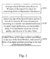
- FIG. 1 showing a flowchart of a method for controlling flows of a logical link layer in an NFC software stack according to a preferred embodiment of the present invention.
- the method comprises following steps of:
- the upper threshold of the Send Window is a serial number of a data frame waited to be transferred next via the output terminal; the lower threshold of the Send Window is the minimal serial number of a data frame which has been transferred via the output terminal but has not been received; the maximal serial number of the data frame is the maximal serial number of a wait-to-be-transferred data frame.
- TooFar represents the upper threshold of the Receive Window
- FrameExpected represents the lower threshold of the Receive Window
- MaxSeq represents the maximal value of the serial number of a wait-to-be-transferred data frame
- Receive Window represents the size of the Receive Window.
- the meaning of these terms is that the upper threshold of the Receive Window is the maximal serial number of a data frame allowed to be received by the input terminal; the lower threshold of the Receive Window is the serial number of a data frame which will be received by the input terminal.
- MOD representing modulo operation
- the steps in this embodiment are not specifically arranged. The arrangement of the above-mentioned steps is merely for explanations. The Send Window at the output terminal and the Receive Window at the input terminal are adjusted through the steps. In this way, bandwidth utilization of the Send Window and the Receive Window is balanced better, and the memory resource is consumed less.
- the Send Window and the Receive Window will be detailed in the following.
- the Send Window is used for controlling flows of the output terminal.
- the Send Window denotes a table of serial numbers of data frames that is sent by the output terminal without receiving a confirmation frame.
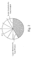
- Fig.2 shows the Send Window with the biggest size of 2 n .
- the serial number of the data frame is from zero to 2 n -1.
- the serial number 2 n -1 is the biggest serial number of the data frame.
- the black part between the upper threshold of the Send Window and the lower threshold of the Send Window represents the size of the Send Window (the table of the serial numbers of the frames that is sent by the output terminal without receiving the confirmation frame).
- the supreme value of the Send Window is chosen to be the serial number of the data frame and the number one is added to the upper threshold of the Send Window.
- the number one is added to the lower threshold of the Send Window.
- the output terminal receives the confirmation frame which is not at the lower threshold of the Send Window (that is, the serial number is smaller than the upper threshold of the Send Window)
- the number one is added to a serial number corresponding to the confirmation frame and the new number is set as the lower threshold of the Send Window to adjust the Send Window and to continue to control the flows of the output terminal.
- the Receive Window determines that the input terminal receives what kind of data frame.
- the input terminal only receives the serial number of the data frame within the Receive Window.
- the upper threshold of the Receive Window represents a data frame having the largest serial number is received by the input terminal.
- the lower threshold of the Receive Window represents a data frame having a desired serial number is received by the input terminal. Any data frame outside the Receive Window is bound to be discarded.
- the size of the Send Window and the size of the Receive Window are statically designated based on empirical values
- the size of the Send Window and the size of the Receive Window are dynamically calculated based on the upper-layer application, the channel quality, and the size of the data frame in each communication in the present invention.
- the upper-layer application ensures the transfer rate of communication.
- the transfer rate may be 106Kbps (bit rate), 212Kbps, or 424Kbps.
- the variable DATARATE_MAX represents the transfer rate (generally, the transfer rate is the maximal transfer rate ensured in the upper-layer application).
- the variable DATARATE_MAX can be read in a generic gate (ETSI TS 102 622 standard nomenclature) of the NFC controller at the input terminal in communication.
- the channel quality ensures the communication delay time between two NFC devices.
- the communication delay time is from 302us to 4949ms.
- a variable FWT indicates the communication delay time.
- the variable FWT will be read from the generic gate in the NFC controller at the input terminal when the communication works.
- the size of data frames adopted in the Logical Link Control Protocol differs with different communication objects. Communicators have to specify Link Maximum Information Unit (Link MIU) to connect to each other. The size of data frames can be calculated based on the Link MIU.
- Link MIU Link Maximum Information Unit
- Receive Window FWT ⁇ DATARATE_MAX / 2 + Link Miu ⁇ 8
- the size of the Send Window is designed to be identical to the size of the Receive Window. But the variables FWT and DATARATE_MAX are read by the NFC controller at the output terminal to obtain the size of the Send Window.
- the above-mentioned steps solve the struggle between bandwidth utilization and memory resource consumption successfully.
- the size of the Send Window and the size of the Receive Window are dynamically adjustable instead of statically designated. In this way, the bandwidth utilization is balanced and the memory resource is consumed less.
- a buffer zone is built at the input terminal for buffering the received data frame.
- the data frame is deposited in the buffer zone.
- Fig.3 shows steps comprising:
- the present invention has benefits of balancing bandwidth utilization and reducing consumption of memory resource by arranging a Send Window and a Receive Window in the logical link layer for controlling flows of transmitted data frames and adjusting the size of the Send Window and the size of the Receive Window dynamically based on the upper-layer application, the channel quality, and the size of the data frame.
Landscapes
- Engineering & Computer Science (AREA)
- Computer Networks & Wireless Communication (AREA)
- Signal Processing (AREA)
- Data Exchanges In Wide-Area Networks (AREA)
- Communication Control (AREA)
- Mobile Radio Communication Systems (AREA)
Abstract
Description
- The present invention relates to the field of wireless communication technology, and more particularly, to a method for controlling flows of a logical link layer in near field communication (NFC) software stack.
- Contactless radio frequency identification (RFID) technology and interconnection and intercommunication technology are integrated and the NFC technology is produced. To improve development and popularity of the NFC technology, an NFC forum is organized by the industry. The NFC forum defines the NFC protocol system where the NFC software stack is a middleware for supporting applying development in the upper layer and for operating an NFC controller in the lower layer. A data connecting layer is arranged in the NFC software stack. The data connecting layer is basically used for transferring transparent and reliable data to a user of its layer. In addition, the data connecting layer is used for framing, error correction, conservation, and flow control.
- A traditional NFC Forum Logical Link Protocol does not regulate the size of a Receive Window; instead, the size of the Receive Window is recommended to be zero to 15 in the Protocol. The NFC Protocol has a physical layer, which is a wireless communication protocol, and the physical layer tends to make troubles. The smaller the Receive Window is, the larger the bandwidth needs. The Logical Link Protocol is a Peer to Peer (P2P) business service. This kind of business service has a larger amount of data and a larger corresponding data frame. Thus, a larger buffer zone is required when the size of the Receive Window is much larger. However, the NFC software stack works in an embedded environment, so memory resource of the NFC software stack is relatively limited. Once the buffer zone becomes larger, the performance of the system will be affected.
- In addition, a plurality of NFC controller chips support the P2P application only in the passive mode. The mode is a half-duplex working mode, which means that the actions "send" and "receive" take turns. If the size of the Send Window and the size of the Receive Window are too large, one of the communicators is in state of sending and resending all the time, and the other is deprived of sending time, resulting in the struggle between unbalance of bandwidth utilization and consumption of memory resource.
- Therefore, the conventional technology has room to be improved.
- In light of imperfectness of the conventional technology, an object of the present invention is to provide a method for controlling flows of a logical link layer in an NFC software stack for solving problems such as unbalance of bandwidth utilization and large consumption of memory resource in the NFC in the conventional technology.
- According to the present invention, a method for controlling flows of a logical link layer in a near field communication (NFC) software stack, comprises steps of:
- Step A: arranging a Send Window and a Receive Window in the logical link layer for controlling flows of transmitted data frames;
- Step B: adjusting the size of the Send Window and the size of the Receive Window according to a transfer rate determined based on upper-layer application, communication delay time determined based on channel quality, and the size of a data frame, and the size of the Receive Window satisfying an equation taking on the form of Receive Window = [FWT×DATARATE_MAX]/[(2+Link Miu)×8] where Receive Window represents the size of the Receive Window, FWT represents the communication delay time, DATARATE_MAX represents transfer rate, and Link Miu represents a parameter designated when an output terminal and an input terminal are connected, and FWT and DATARATE_MAX being read by an NFC controller at the input terminal; and
- Step C: controlling flows of the output terminal according to the size of the Send Window, and controlling flows of the input terminal according to the size of the Receive Window.
- In one aspect of the present invention, the transfer rate is 106Kbps (bit rate), 212Kbps, or 424Kbps.
- In another aspect of the present invention, a buffer zone is constructed at the input terminal for buffering the received data frame.
- In another aspect of the present invention, that the input terminal receives the data frame comprises steps of:
- Step A1: receiving the data frame sent by the output terminal through the input terminal;
- Step A2: judging a serial number of the data frame to be in the Receive Window;
- Step A3: judging the serial number of the data frame to be the lower threshold of the Receive Window when the serial number of the data frame is in the Receive Window;
- Step A4: moving a data frame corresponding to the serial number of the data frame to the buffer zone when the serial number of the data frame is not the lower threshold of the Receive Window;
- Step A5: looking up the data frame forming a continuous series with the serial numbers of the data frame in the buffer zone when the serial number of the data frame is the lower threshold of the Receive Window;
- Step A6: returning a confirmation frame to the input terminal when the data frame forming a continuous series with the serial numbers of the data frame is not found in the buffer zone, and confirming the serial number of the data frame is the data frame in the lower threshold of the Receive Window; and
- Step A7: forming the received data frame and the data frame capable of forming a continuous series to form a data frame unit when the data frame forming a continuous series with the serial numbers of the data frame is found in the buffer zone, returning a confirmation frame to the input terminal, confirming to receive a data frame having a largest serial number in the data frame unit: an i data frame.
- In another aspect of the present invention, after the confirmation frame is returned according to Step A7, the lower threshold of the Receive Window set as FrameExpected = i + 1, and the upper threshold of the Receive Window set as TooFar = (i + Receive Window) MOD (MaxSeq + 1) in which FrameExpected represents the lower threshold of the Receive Window, TooFar represents the upper threshold of the Receive Window, MaxSeq represents the maximal value of the serial number of a wait-to-be-transferred data frame, and MOD represents modulo operation.
- In still another aspect of the present invention, the number one is added to the upper threshold of the Send Window when the output terminal sends a new data frame.
- In yet another aspect of the present invention, the confirmation frame is checked to be a confirmation frame corresponding to the lower threshold of the Send Window when the output terminal receives the confirmation frame returned by the input terminal, if it is, the number one is added to the lower threshold of the Send Window, and if not, the number one is added to the serial number of the confirmation frame for being the lower threshold of a new Send Window.
- According to the present invention, a method for controlling flows of a logical link layer in a near field communication (NFC) software stack comprises steps of:
- Step A: arranging a Send Window and a Receive Window in the logical link layer for controlling flows of transmitted data frames;
- Step B: adjusting the size of the Send Window and the size of the Receive Window according to a transfer rate determined based on upper-layer application, communication delay time determined based on channel quality, and the size of a data frame,; and
- Step C: controlling flows of the output terminal according to the size of the Send Window, and controlling flows of the input terminal according to the size of the Receive Window.
- In one aspect of the present invention, the size of the Receive Window satisfying an equation taking on the form of Receive Window = [FWT×DATARATE_MAX]/[(2+Link Miu)×8] where Receive Window represents the size of the Receive Window, FWT represents the communication delay time, DATARATE_MAX represents transfer rate, and Link Miu represents a parameter designated when an output terminal and an input terminal are connected.
- In another aspect of the present invention, the transfer rate is 106Kbps (bit rate), 212Kbps, or 424Kbps.
- In another aspect of the present invention, a buffer zone is constructed at the input terminal for buffering the received data frame.
- In another aspect of the present invention, that the input terminal receives the data frame comprises steps of:
- Step A1: receiving the data frame sent by the output terminal through the input terminal;
- Step A2: judging a serial number of the data frame to be in the Receive Window;
- Step A3: judging the serial number of the data frame to be the lower threshold of the Receive Window when the serial number of the data frame is in the Receive Window;
- Step A4: moving a data frame corresponding to the serial number of the data frame to the buffer zone when the serial number of the data frame is not the lower threshold of the Receive Window;
- Step A5: looking up the data frame forming a continuous series with the serial numbers of the data frame in the buffer zone when the serial number of the data frame is the lower threshold of the Receive Window;
- Step A6: returning a confirmation frame to the input terminal when the data frame forming a continuous series with the serial numbers of the data frame is not found in the buffer zone, and confirming the serial number of the data frame is the data frame in the lower threshold of the Receive Window; and
- Step A7: forming the received data frame and the data frame capable of forming a continuous series to form a data frame unit when the data frame forming a continuous series with the serial numbers of the data frame is found in the buffer zone, returning a confirmation frame to the input terminal, confirming to receive a data frame having a largest serial number in the data frame unit: an i data frame.
- In another aspect of the present invention, after the confirmation frame is returned according to Step A7, the lower threshold of the Receive Window set as FrameExpected = i + 1, and the upper threshold of the Receive Window set as TooFar = (i + Receive Window) MOD (MaxSeq + 1) in which FrameExpected represents the lower threshold of the Receive Window, TooFar represents the upper threshold of the Receive Window, MaxSeq represents the maximal value of the serial number of a wait-to-be-transferred data frame, and MOD represents modulo operation.
- In still another aspect of the present invention, the number one is added to the upper threshold of the Send Window when the output terminal sends a new data frame.
- In yet another aspect of the present invention, the confirmation frame is checked to be a confirmation frame corresponding to the lower threshold of the Send Window when the output terminal receives the confirmation frame returned by the input terminal, if it is, the number one is added to the lower threshold of the Send Window, and if not, the number one is added to the serial number of the confirmation frame for being the lower threshold of a new Send Window.
- Compared with the conventional technology, the present invention has benefits of balancing bandwidth utilization and greatly reducing consumption of memory resource by arranging a Send Window and a Receive Window in the logical link layer for controlling flows of transmitted data frames and adjusting the size of the Send Window and the size of the Receive Window dynamically based on upper-layer application, channel quality, and the size of the data frame.
-
-
Fig. 1 shows a flowchart of a method for controlling flows of a logical link layer in an NFC software stack according to a preferred embodiment of the present invention. -
Fig. 2 illustrates a schematic diagram of a Send Window according to a preferred embodiment of the present invention. -
Fig. 3 shows a flowchart of receiving data frame according to a preferred embodiment of the present invention. - In order to illustrate the technique and effects of the present invention, a detailed description will be disclosed by the following disclosure in conjunction with figures.
- Please refer to
Fig. 1 showing a flowchart of a method for controlling flows of a logical link layer in an NFC software stack according to a preferred embodiment of the present invention. The method comprises following steps of: - S101: arranging a Send Window and a Receive Window in the logical link layer for controlling flows of transmitted data frames;
- S102: adjusting the size of the Send Window and the size of the Receive Window dynamically according to a transfer rate determined based on upper-layer application, communication delay time determined based on channel quality, and the size of the data frame;
- S103: controlling flows of an output terminal according to the size of the Send Window, and controlling flows of an input terminal according to the size of the Receive Window.
- The size of the Send Window takes on the form of Send Window = (NextFrameToSend - AckExpected) MOD (MaxSeq + 1) where Send Window represents the size of the Send Window, NextFrameToSend represents the upper threshold of the Send Window, AckExpected represents the lower threshold of the Send Window, and MaxSeq represents the maximal value of the serial number of the wait-to-be-transferred data frame. The meaning of these terms is that the upper threshold of the Send Window is a serial number of a data frame waited to be transferred next via the output terminal; the lower threshold of the Send Window is the minimal serial number of a data frame which has been transferred via the output terminal but has not been received; the maximal serial number of the data frame is the maximal serial number of a wait-to-be-transferred data frame.
- The size of the Receive Window takes on the form of TooFar = (FrameExpected + Receive Window) MOD (MaxSeq + 1) where TooFar represents the upper threshold of the Receive Window, FrameExpected represents the lower threshold of the Receive Window, MaxSeq represents the maximal value of the serial number of a wait-to-be-transferred data frame, and Receive Window represents the size of the Receive Window. The meaning of these terms is that the upper threshold of the Receive Window is the maximal serial number of a data frame allowed to be received by the input terminal; the lower threshold of the Receive Window is the serial number of a data frame which will be received by the input terminal.
- MOD, representing modulo operation, is a frequently used binary operation. For example, when the form of a = bq + r where q is an integral and the integral is maximal stands, aMODb = r stands. In addition, the steps in this embodiment are not specifically arranged. The arrangement of the above-mentioned steps is merely for explanations. The Send Window at the output terminal and the Receive Window at the input terminal are adjusted through the steps. In this way, bandwidth utilization of the Send Window and the Receive Window is balanced better, and the memory resource is consumed less.
- The Send Window and the Receive Window will be detailed in the following.
- The Send Window is used for controlling flows of the output terminal. The Send Window denotes a table of serial numbers of data frames that is sent by the output terminal without receiving a confirmation frame.
Fig.2 shows the Send Window with the biggest size of 2n. The serial number of the data frame is from zero to 2n-1. The serial number 2n-1 is the biggest serial number of the data frame. The black part between the upper threshold of the Send Window and the lower threshold of the Send Window represents the size of the Send Window (the table of the serial numbers of the frames that is sent by the output terminal without receiving the confirmation frame). When the output terminal sends a new data frame, the supreme value of the Send Window is chosen to be the serial number of the data frame and the number one is added to the upper threshold of the Send Window. When the output terminal receives the confirmation frame at the lower threshold of the Send Window, the number one is added to the lower threshold of the Send Window. When the output terminal receives the confirmation frame which is not at the lower threshold of the Send Window (that is, the serial number is smaller than the upper threshold of the Send Window), the number one is added to a serial number corresponding to the confirmation frame and the new number is set as the lower threshold of the Send Window to adjust the Send Window and to continue to control the flows of the output terminal. - The Receive Window determines that the input terminal receives what kind of data frame. The input terminal only receives the serial number of the data frame within the Receive Window. The upper threshold of the Receive Window represents a data frame having the largest serial number is received by the input terminal. The lower threshold of the Receive Window represents a data frame having a desired serial number is received by the input terminal. Any data frame outside the Receive Window is bound to be discarded.
- To balance the struggle between bandwidth utilization and consumption of memory resource, instead of adopting the conventional technology where the size of the Send Window and the size of the Receive Window are statically designated based on empirical values, the size of the Send Window and the size of the Receive Window are dynamically calculated based on the upper-layer application, the channel quality, and the size of the data frame in each communication in the present invention.
- Take the input terminal for example. The upper-layer application ensures the transfer rate of communication. The transfer rate may be 106Kbps (bit rate), 212Kbps, or 424Kbps. The variable DATARATE_MAX represents the transfer rate (generally, the transfer rate is the maximal transfer rate ensured in the upper-layer application). The variable DATARATE_MAX can be read in a generic gate (ETSI TS 102 622 standard nomenclature) of the NFC controller at the input terminal in communication.
- The channel quality ensures the communication delay time between two NFC devices. The communication delay time is from 302us to 4949ms. A variable FWT indicates the communication delay time. The variable FWT will be read from the generic gate in the NFC controller at the input terminal when the communication works.
- The size of data frames adopted in the Logical Link Control Protocol differs with different communication objects. Communicators have to specify Link Maximum Information Unit (Link MIU) to connect to each other. The size of data frames can be calculated based on the Link MIU.
- In this way, a desired parameter is produced. Then, the size of the Receive Window takes on the form:

- Meanwhile, the size of the Send Window is designed to be identical to the size of the Receive Window. But the variables FWT and DATARATE_MAX are read by the NFC controller at the output terminal to obtain the size of the Send Window. The above-mentioned steps solve the struggle between bandwidth utilization and memory resource consumption successfully. The size of the Send Window and the size of the Receive Window are dynamically adjustable instead of statically designated. In this way, the bandwidth utilization is balanced and the memory resource is consumed less.
- For the input terminal, a buffer zone is built at the input terminal for buffering the received data frame. When a data frame from the Receive Window and not from the lower threshold of the Receive Window is received, the data frame is deposited in the buffer zone.
Fig.3 shows steps comprising: - S201: receiving the data frame sent by the output terminal via the input terminal;
- S202: judging the serial number of the data frame to be in the Receive Window;
- S203: judging the serial number of the data frame to be the lower threshold of the Receive Window when the serial number of the data frame is in the Receive Window; deleting the data frame once the serial number of the data frame is not in the Receive Window and entering Step 208;
- S204: moving the data frame corresponding to the serial number of the data frame to the buffer zone when the serial number of the data frame is not the lower threshold of the Receive Window;
- S205: looking up the data frame forming a continuous series with the serial numbers of the data frame in the buffer zone when the serial number of the data frame is the lower threshold of the Receive Window;
- S206: returning a confirmation frame to the input terminal when the data frame forming a continuous series with the serial numbers of the data frame is not found in the buffer zone, and confirming the serial number of the data frame to be the data frame in the lower threshold of the Receive Window;
- S207: forming the received data frame and the data frame capable of forming a continuous series to form a data frame unit when the data frame forming a continuous series with the serial numbers of the data frame is found in the buffer zone, returning a confirmation frame to the input terminal, confirming to receive a data frame having a largest serial number in the data frame unit: an i data frame;
- S208: discarding the data frame.
- After the confirmation frame is returned according to Step S207, the Receive Window is adjusted: the lower threshold of the Receive Window set as FrameExpected = i + 1, and the upper threshold of the Receive Window set as TooFar = (i + Receive Window) MOD (MaxSeq + 1).
- In sum, the present invention has benefits of balancing bandwidth utilization and reducing consumption of memory resource by arranging a Send Window and a Receive Window in the logical link layer for controlling flows of transmitted data frames and adjusting the size of the Send Window and the size of the Receive Window dynamically based on the upper-layer application, the channel quality, and the size of the data frame.
- The present invention has been described with reference to certain preferred and alternative embodiments which are intended to be exemplary only and not limited to the full scope of the present invention as set forth in the appended claims.
Claims (15)
- A method for controlling flows of a logical link layer in a near field communication (NFC) software stack, comprising steps of:Step A: arranging a Send Window and a Receive Window in the logical link layer for controlling flows of transmitted data frames;Step B: adjusting the size of the Send Window and the size of the Receive Window according to a transfer rate determined based on upper-layer application, communication delay time determined based on channel quality, and the size of a data frame, and the size of the Receive Window satisfying an equation taking on the form of Receive Window = [FWT×DATARATE_MAX]/[(2+Link Miu)×8] where Receive Window represents the size of the Receive Window, FWT represents the communication delay time, DATARATE_MAX represents transfer rate, and Link Miu represents a parameter designated when an output terminal and an input terminal are connected, and FWT and DATARATE_MAX being read by an NFC controller at the input terminal; andStep C: controlling flows of the output terminal according to the size of the Send Window, and controlling flows of the input terminal according to the size of the Receive Window.
- The method as claimed in claim 1, wherein the transfer rate is 106Kbps (bit rate), 212Kbps, or 424Kbps.
- The method as claimed in claim 1, wherein a buffer zone is constructed at the input terminal for buffering the received data frame.
- The method as claimed in claim 3, wherein that the input terminal receives the data frame comprises steps of:Step A1: receiving the data frame sent by the output terminal through the input terminal;Step A2: judging a serial number of the data frame to be in the Receive Window;Step A3: judging the serial number of the data frame to be the lower threshold of the Receive Window when the serial number of the data frame is in the Receive Window;Step A4: moving a data frame corresponding to the serial number of the data frame to the buffer zone when the serial number of the data frame is not the lower threshold of the Receive Window;Step A5: looking up the data frame forming a continuous series with the serial numbers of the data frame in the buffer zone when the serial number of the data frame is the lower threshold of the Receive Window;Step A6: returning a confirmation frame to the input terminal when the data frame forming a continuous series with the serial numbers of the data frame is not found in the buffer zone, and confirming the serial number of the data frame is the data frame in the lower threshold of the Receive Window; andStep A7: forming the received data frame and the data frame capable of forming a continuous series to form a data frame unit when the data frame forming a continuous series with the serial numbers of the data frame is found in the buffer zone, returning a confirmation frame to the input terminal, confirming to receive a data frame having a largest serial number in the data frame unit: an i data frame.
- The method as claimed in claim 4, wherein after the confirmation frame is returned according to Step A7, the lower threshold of the Receive Window set as FrameExpected = i + 1, and the upper threshold of the Receive Window set as TooFar = (i + Receive Window) MOD (MaxSeq + 1) in which FrameExpected represents the lower threshold of the Receive Window, TooFar represents the upper threshold of the Receive Window, MaxSeq represents the maximal value of the serial number of a wait-to-be-transferred data frame, and MOD represents modulo operation.
- The method as claimed in claim 5, wherein the number one is added to the upper threshold of the Send Window when the output terminal sends a new data frame.
- The method as claimed in claim 5, wherein the confirmation frame is checked to be a confirmation frame corresponding to the lower threshold of the Send Window when the output terminal receives the confirmation frame returned by the input terminal, if it is, the number one is added to the lower threshold of the Send Window, and if not, the number one is added to the serial number of the confirmation frame for being the lower threshold of a new Send Window.
- A method for controlling flows of a logical link layer in a near field communication (NFC) software stack, comprising steps of:Step A: arranging a Send Window and a Receive Window in the logical link layer for controlling flows of transmitted data frames;Step B: adjusting the size of the Send Window and the size of the Receive Window according to a transfer rate determined based on upper-layer application, communication delay time determined based on channel quality, and the size of a data frame,; andStep C: controlling flows of the output terminal according to the size of the Send Window, and controlling flows of the input terminal according to the size of the Receive Window.
- The method as claimed in claim 8, wherein the size of the Receive Window satisfying an equation taking on the form of Receive Window = [FWT×DATARATE_MAX]/[(2+Link Miu)×8] where Receive Window represents the size of the Receive Window, FWT represents the communication delay time, DATARATE_MAX represents transfer rate, and Link Miu represents a parameter designated when an output terminal and an input terminal are connected.
- The method as claimed in claim 9, wherein the transfer rate is 106Kbps (bit rate), 212Kbps, or 424Kbps.
- The method as claimed in claim 9, wherein a buffer zone is constructed at the input terminal for buffering the received data frame.
- The method as claimed in claim 11, wherein that the input terminal receives the data frame comprises steps of:Step A1: receiving the data frame sent by the output terminal through the input terminal;Step A2: judging a serial number of the data frame to be in the Receive Window;Step A3: judging the serial number of the data frame to be the lower threshold of the Receive Window when the serial number of the data frame is in the Receive Window;Step A4: moving a data frame corresponding to the serial number of the data frame to the buffer zone when the serial number of the data frame is not the lower threshold of the Receive Window;Step A5: looking up the data frame forming a continuous series with the serial numbers of the data frame in the buffer zone when the serial number of the data frame is the lower threshold of the Receive Window;Step A6: returning a confirmation frame to the input terminal when the data frame forming a continuous series with the serial numbers of the data frame is not found in the buffer zone, and confirming the serial number of the data frame is the data frame in the lower threshold of the Receive Window; andStep A7: forming the received data frame and the data frame capable of forming a continuous series to form a data frame unit when the data frame forming a continuous series with the serial numbers of the data frame is found in the buffer zone, returning a confirmation frame to the input terminal, confirming to receive a data frame having a largest serial number in the data frame unit: an i data frame.
- The method as claimed in claim 12, wherein after the confirmation frame is returned according to Step A7, the lower threshold of the Receive Window set as FrameExpected = i + 1, and the upper threshold of the Receive Window set as TooFar = (i + Receive Window) MOD (MaxSeq + 1) in which FrameExpected represents the lower threshold of the Receive Window, TooFar represents the upper threshold of the Receive Window, MaxSeq represents the maximal value of the serial number of a wait-to-be-transferred data frame, and MOD represents modulo operation.
- The method as claimed in claim 13, wherein the number one is added to the upper threshold of the Send Window when the output terminal sends a new data frame.
- The method as claimed in claim 13, wherein the confirmation frame is checked to be a confirmation frame corresponding to the lower threshold of the Send Window when the output terminal receives the confirmation frame returned by the input terminal, if it is, the number one is added to the lower threshold of the Send Window, and if not, the number one is added to the serial number of the confirmation frame for being the lower threshold of a new Send Window.
Applications Claiming Priority (2)
| Application Number | Priority Date | Filing Date | Title |
|---|---|---|---|
| CN201210518744.3A CN103051558B (en) | 2012-12-06 | 2012-12-06 | A kind of flow control methods of near-field communication software stack logic link layer |
| PCT/CN2013/079965 WO2014086154A1 (en) | 2012-12-06 | 2013-07-24 | Traffic control method for near-field communication software stack logic link layer |
Publications (3)
| Publication Number | Publication Date |
|---|---|
| EP2930895A1 true EP2930895A1 (en) | 2015-10-14 |
| EP2930895A4 EP2930895A4 (en) | 2016-07-20 |
| EP2930895B1 EP2930895B1 (en) | 2020-04-15 |
Family
ID=48064063
Family Applications (1)
| Application Number | Title | Priority Date | Filing Date |
|---|---|---|---|
| EP13859956.8A Active EP2930895B1 (en) | 2012-12-06 | 2013-07-24 | Traffic control method for near-field communication software stack logic link layer |
Country Status (4)
| Country | Link |
|---|---|
| US (1) | US9264106B2 (en) |
| EP (1) | EP2930895B1 (en) |
| CN (1) | CN103051558B (en) |
| WO (1) | WO2014086154A1 (en) |
Families Citing this family (7)
| Publication number | Priority date | Publication date | Assignee | Title |
|---|---|---|---|---|
| CN103051558B (en) | 2012-12-06 | 2016-06-15 | 惠州Tcl移动通信有限公司 | A kind of flow control methods of near-field communication software stack logic link layer |
| CN106470448B (en) * | 2015-08-14 | 2020-10-30 | 中兴通讯股份有限公司 | Method and device for receiving signaling of base station |
| CN114008952A (en) * | 2019-09-23 | 2022-02-01 | Oppo广东移动通信有限公司 | Window adjusting method and device, network equipment and terminal equipment |
| CN111049754B (en) * | 2019-12-18 | 2023-01-10 | 上海众源网络有限公司 | Data communication method, device, equipment and computer readable storage medium |
| CN113872726B (en) * | 2020-06-30 | 2023-03-03 | 华为技术有限公司 | Method, device and system for adjusting sending rate in near field communication scene |
| CN114095126A (en) * | 2021-11-11 | 2022-02-25 | 北京邮电大学 | A data transmission rate adjustment method, system and device |
| CN115119216B (en) * | 2022-06-24 | 2024-05-14 | 深圳友讯达科技股份有限公司 | LoRaWAN network communication method and system with constant power supply |
Family Cites Families (19)
| Publication number | Priority date | Publication date | Assignee | Title |
|---|---|---|---|---|
| US6198941B1 (en) * | 1998-08-07 | 2001-03-06 | Lucent Technologies Inc. | Method of operating a portable communication device |
| AU4373799A (en) * | 1999-06-04 | 2000-12-28 | Nokia Corporation | Packet data transmission control |
| JP3805569B2 (en) * | 1999-07-08 | 2006-08-02 | 富士通株式会社 | Control device having window control function, storage medium storing window control program, and communication control device having window control function |
| WO2001022646A1 (en) * | 1999-09-20 | 2001-03-29 | Nokia Corporation | Cumulative acknowledgement transmission in an automatic repeat request |
| US7616638B2 (en) * | 2003-07-29 | 2009-11-10 | Orbital Data Corporation | Wavefront detection and disambiguation of acknowledgments |
| US7516238B2 (en) * | 2003-09-30 | 2009-04-07 | Microsoft Corporation | Background transport service |
| US8281356B2 (en) * | 2004-11-17 | 2012-10-02 | Sharp Kabushiki Kaisha | Transmitter |
| KR100748086B1 (en) * | 2005-11-10 | 2007-08-09 | 한국전자통신연구원 | Wireless communication channel quality maintenance method and wireless communication device using same |
| JP4511567B2 (en) * | 2006-02-21 | 2010-07-28 | ホアウェイ・テクノロジーズ・カンパニー・リミテッド | Method and system for controlling data transmission rate |
| US8125904B2 (en) * | 2006-05-30 | 2012-02-28 | Broadcom Corporation | Method and system for adaptive queue and buffer control based on monitoring and active congestion avoidance in a packet network switch |
| KR101417937B1 (en) * | 2007-02-06 | 2014-08-05 | 엘지전자 주식회사 | Wireless communication system and its data transmission method |
| CN101159520A (en) * | 2007-10-29 | 2008-04-09 | 中兴通讯股份有限公司 | data transfer method |
| EP2204018B1 (en) * | 2007-11-01 | 2011-04-13 | Telefonaktiebolaget L M Ericsson (publ) | Limiting the rlc window size in a hsdpa flow control |
| US8189532B2 (en) * | 2007-12-26 | 2012-05-29 | Nokia Corporation | Mobile node, a method or handover and a computer program |
| US8737220B2 (en) * | 2008-09-23 | 2014-05-27 | The Trustees Of Columbia University In The City Of New York | Systems for providing feedback to sending entities |
| US8565242B2 (en) * | 2008-11-04 | 2013-10-22 | Blackberry Limited | Transport protocol performance using network bit rate information |
| CN101895332B (en) * | 2010-08-09 | 2012-11-28 | 中国电子科技集团公司第五十四研究所 | Method for controlling spatial TCP flow and controlling error |
| CN102664867B (en) | 2012-03-15 | 2014-11-19 | 南京邮电大学 | An Enhancement Method of Transmission Protocol in Satellite Communication System |
| CN103051558B (en) * | 2012-12-06 | 2016-06-15 | 惠州Tcl移动通信有限公司 | A kind of flow control methods of near-field communication software stack logic link layer |
-
2012
- 2012-12-06 CN CN201210518744.3A patent/CN103051558B/en not_active Expired - Fee Related
-
2013
- 2013-07-24 US US14/388,078 patent/US9264106B2/en active Active
- 2013-07-24 WO PCT/CN2013/079965 patent/WO2014086154A1/en not_active Ceased
- 2013-07-24 EP EP13859956.8A patent/EP2930895B1/en active Active
Also Published As
| Publication number | Publication date |
|---|---|
| US20150065040A1 (en) | 2015-03-05 |
| CN103051558A (en) | 2013-04-17 |
| EP2930895A4 (en) | 2016-07-20 |
| US9264106B2 (en) | 2016-02-16 |
| CN103051558B (en) | 2016-06-15 |
| EP2930895B1 (en) | 2020-04-15 |
| WO2014086154A1 (en) | 2014-06-12 |
Similar Documents
| Publication | Publication Date | Title |
|---|---|---|
| EP2930895B1 (en) | Traffic control method for near-field communication software stack logic link layer | |
| US10789198B2 (en) | Methods and apparatus for reduced-latency data transmission with an inter-processor communication link between independently operable processors | |
| EP2647175B1 (en) | Facilitating device-to-device communication | |
| US11120811B2 (en) | Power optimized link quality detection and feedback | |
| CN103368688B (en) | Data processing equipment | |
| EP3782402B1 (en) | Dynamic bearer validity | |
| JP2022501929A (en) | Data transmission method and equipment | |
| RU2736417C1 (en) | Method for transmission over radio link control protocol and related products | |
| CN112243262B (en) | Electronic device for transmitting data by splitting the carrier and method for operating the electronic device | |
| TWI634430B (en) | Data storage device and methods for controlling a data transfer speed | |
| CN105766020B (en) | Method of controlling transmission power and transmission delay and communication terminal using same | |
| US20150381763A1 (en) | Communication system, control apparatus, application server, and device | |
| JPWO2011158467A1 (en) | Data transmission apparatus and data transmission method | |
| CN102318289B (en) | Bandwidth adjusting method, bus controller and signal converter | |
| RU2725975C1 (en) | Method of transmitting pdu control unit of status report at rlc level and concomitant device | |
| CN107534616B (en) | Quality of service for universal serial bus | |
| CN111817824A (en) | An information transmission method, terminal device and control node | |
| CN114258157A (en) | Aggregation configuration method, device and terminal | |
| US9210718B2 (en) | Method and apparatus for improving transmission resource utilization | |
| CN120358623B (en) | Priority adjustment method, storage medium, chip system and communication system | |
| WO2016026323A1 (en) | Method and apparatus for sending response information and computer storage medium | |
| CN101499964A (en) | Method for improving CPRI interface transmission bandwidth utilization, CPRI interface processing module and equipment | |
| CN115189822B (en) | Data transmission method and device, UE and readable storage device | |
| CN104113835A (en) | Ciphertext sending and transmitting method, mobile terminal and communication base station | |
| WO2018006394A1 (en) | Dynamic segmentation |
Legal Events
| Date | Code | Title | Description |
|---|---|---|---|
| PUAI | Public reference made under article 153(3) epc to a published international application that has entered the european phase |
Free format text: ORIGINAL CODE: 0009012 |
|
| 17P | Request for examination filed |
Effective date: 20150630 |
|
| AK | Designated contracting states |
Kind code of ref document: A1 Designated state(s): AL AT BE BG CH CY CZ DE DK EE ES FI FR GB GR HR HU IE IS IT LI LT LU LV MC MK MT NL NO PL PT RO RS SE SI SK SM TR |
|
| AX | Request for extension of the european patent |
Extension state: BA ME |
|
| DAX | Request for extension of the european patent (deleted) | ||
| RA4 | Supplementary search report drawn up and despatched (corrected) |
Effective date: 20160621 |
|
| RIC1 | Information provided on ipc code assigned before grant |
Ipc: H04L 12/807 20130101ALI20160615BHEP Ipc: H04W 72/04 20090101ALI20160615BHEP Ipc: H04L 1/18 20060101ALI20160615BHEP Ipc: H04B 5/00 20060101ALI20160615BHEP Ipc: H04L 12/861 20130101AFI20160615BHEP Ipc: H04W 4/00 20090101ALI20160615BHEP |
|
| STAA | Information on the status of an ep patent application or granted ep patent |
Free format text: STATUS: EXAMINATION IS IN PROGRESS |
|
| 17Q | First examination report despatched |
Effective date: 20180920 |
|
| GRAP | Despatch of communication of intention to grant a patent |
Free format text: ORIGINAL CODE: EPIDOSNIGR1 |
|
| STAA | Information on the status of an ep patent application or granted ep patent |
Free format text: STATUS: GRANT OF PATENT IS INTENDED |
|
| RIC1 | Information provided on ipc code assigned before grant |
Ipc: H04W 4/00 20180101ALI20191119BHEP Ipc: H04W 72/04 20090101ALI20191119BHEP Ipc: H04L 1/18 20060101ALI20191119BHEP Ipc: H04B 5/00 20060101ALI20191119BHEP Ipc: H04L 12/807 20130101ALI20191119BHEP Ipc: H04L 12/861 20130101AFI20191119BHEP Ipc: H04W 4/80 20180101ALI20191119BHEP |
|
| INTG | Intention to grant announced |
Effective date: 20191219 |
|
| GRAS | Grant fee paid |
Free format text: ORIGINAL CODE: EPIDOSNIGR3 |
|
| GRAA | (expected) grant |
Free format text: ORIGINAL CODE: 0009210 |
|
| STAA | Information on the status of an ep patent application or granted ep patent |
Free format text: STATUS: THE PATENT HAS BEEN GRANTED |
|
| AK | Designated contracting states |
Kind code of ref document: B1 Designated state(s): AL AT BE BG CH CY CZ DE DK EE ES FI FR GB GR HR HU IE IS IT LI LT LU LV MC MK MT NL NO PL PT RO RS SE SI SK SM TR |
|
| REG | Reference to a national code |
Ref country code: CH Ref legal event code: EP |
|
| REG | Reference to a national code |
Ref country code: DE Ref legal event code: R096 Ref document number: 602013068039 Country of ref document: DE |
|
| REG | Reference to a national code |
Ref country code: IE Ref legal event code: FG4D |
|
| REG | Reference to a national code |
Ref country code: AT Ref legal event code: REF Ref document number: 1258609 Country of ref document: AT Kind code of ref document: T Effective date: 20200515 |
|
| REG | Reference to a national code |
Ref country code: NL Ref legal event code: MP Effective date: 20200415 |
|
| REG | Reference to a national code |
Ref country code: LT Ref legal event code: MG4D |
|
| PG25 | Lapsed in a contracting state [announced via postgrant information from national office to epo] |
Ref country code: SE Free format text: LAPSE BECAUSE OF FAILURE TO SUBMIT A TRANSLATION OF THE DESCRIPTION OR TO PAY THE FEE WITHIN THE PRESCRIBED TIME-LIMIT Effective date: 20200415 Ref country code: NO Free format text: LAPSE BECAUSE OF FAILURE TO SUBMIT A TRANSLATION OF THE DESCRIPTION OR TO PAY THE FEE WITHIN THE PRESCRIBED TIME-LIMIT Effective date: 20200715 Ref country code: GR Free format text: LAPSE BECAUSE OF FAILURE TO SUBMIT A TRANSLATION OF THE DESCRIPTION OR TO PAY THE FEE WITHIN THE PRESCRIBED TIME-LIMIT Effective date: 20200716 Ref country code: FI Free format text: LAPSE BECAUSE OF FAILURE TO SUBMIT A TRANSLATION OF THE DESCRIPTION OR TO PAY THE FEE WITHIN THE PRESCRIBED TIME-LIMIT Effective date: 20200415 Ref country code: PT Free format text: LAPSE BECAUSE OF FAILURE TO SUBMIT A TRANSLATION OF THE DESCRIPTION OR TO PAY THE FEE WITHIN THE PRESCRIBED TIME-LIMIT Effective date: 20200817 Ref country code: IS Free format text: LAPSE BECAUSE OF FAILURE TO SUBMIT A TRANSLATION OF THE DESCRIPTION OR TO PAY THE FEE WITHIN THE PRESCRIBED TIME-LIMIT Effective date: 20200815 Ref country code: NL Free format text: LAPSE BECAUSE OF FAILURE TO SUBMIT A TRANSLATION OF THE DESCRIPTION OR TO PAY THE FEE WITHIN THE PRESCRIBED TIME-LIMIT Effective date: 20200415 Ref country code: LT Free format text: LAPSE BECAUSE OF FAILURE TO SUBMIT A TRANSLATION OF THE DESCRIPTION OR TO PAY THE FEE WITHIN THE PRESCRIBED TIME-LIMIT Effective date: 20200415 |
|
| REG | Reference to a national code |
Ref country code: AT Ref legal event code: MK05 Ref document number: 1258609 Country of ref document: AT Kind code of ref document: T Effective date: 20200415 |
|
| PG25 | Lapsed in a contracting state [announced via postgrant information from national office to epo] |
Ref country code: LV Free format text: LAPSE BECAUSE OF FAILURE TO SUBMIT A TRANSLATION OF THE DESCRIPTION OR TO PAY THE FEE WITHIN THE PRESCRIBED TIME-LIMIT Effective date: 20200415 Ref country code: RS Free format text: LAPSE BECAUSE OF FAILURE TO SUBMIT A TRANSLATION OF THE DESCRIPTION OR TO PAY THE FEE WITHIN THE PRESCRIBED TIME-LIMIT Effective date: 20200415 Ref country code: BG Free format text: LAPSE BECAUSE OF FAILURE TO SUBMIT A TRANSLATION OF THE DESCRIPTION OR TO PAY THE FEE WITHIN THE PRESCRIBED TIME-LIMIT Effective date: 20200715 Ref country code: HR Free format text: LAPSE BECAUSE OF FAILURE TO SUBMIT A TRANSLATION OF THE DESCRIPTION OR TO PAY THE FEE WITHIN THE PRESCRIBED TIME-LIMIT Effective date: 20200415 |
|
| PG25 | Lapsed in a contracting state [announced via postgrant information from national office to epo] |
Ref country code: AL Free format text: LAPSE BECAUSE OF FAILURE TO SUBMIT A TRANSLATION OF THE DESCRIPTION OR TO PAY THE FEE WITHIN THE PRESCRIBED TIME-LIMIT Effective date: 20200415 |
|
| REG | Reference to a national code |
Ref country code: DE Ref legal event code: R097 Ref document number: 602013068039 Country of ref document: DE |
|
| PG25 | Lapsed in a contracting state [announced via postgrant information from national office to epo] |
Ref country code: RO Free format text: LAPSE BECAUSE OF FAILURE TO SUBMIT A TRANSLATION OF THE DESCRIPTION OR TO PAY THE FEE WITHIN THE PRESCRIBED TIME-LIMIT Effective date: 20200415 Ref country code: DK Free format text: LAPSE BECAUSE OF FAILURE TO SUBMIT A TRANSLATION OF THE DESCRIPTION OR TO PAY THE FEE WITHIN THE PRESCRIBED TIME-LIMIT Effective date: 20200415 Ref country code: SM Free format text: LAPSE BECAUSE OF FAILURE TO SUBMIT A TRANSLATION OF THE DESCRIPTION OR TO PAY THE FEE WITHIN THE PRESCRIBED TIME-LIMIT Effective date: 20200415 Ref country code: EE Free format text: LAPSE BECAUSE OF FAILURE TO SUBMIT A TRANSLATION OF THE DESCRIPTION OR TO PAY THE FEE WITHIN THE PRESCRIBED TIME-LIMIT Effective date: 20200415 Ref country code: AT Free format text: LAPSE BECAUSE OF FAILURE TO SUBMIT A TRANSLATION OF THE DESCRIPTION OR TO PAY THE FEE WITHIN THE PRESCRIBED TIME-LIMIT Effective date: 20200415 Ref country code: IT Free format text: LAPSE BECAUSE OF FAILURE TO SUBMIT A TRANSLATION OF THE DESCRIPTION OR TO PAY THE FEE WITHIN THE PRESCRIBED TIME-LIMIT Effective date: 20200415 Ref country code: ES Free format text: LAPSE BECAUSE OF FAILURE TO SUBMIT A TRANSLATION OF THE DESCRIPTION OR TO PAY THE FEE WITHIN THE PRESCRIBED TIME-LIMIT Effective date: 20200415 Ref country code: CZ Free format text: LAPSE BECAUSE OF FAILURE TO SUBMIT A TRANSLATION OF THE DESCRIPTION OR TO PAY THE FEE WITHIN THE PRESCRIBED TIME-LIMIT Effective date: 20200415 |
|
| PLBE | No opposition filed within time limit |
Free format text: ORIGINAL CODE: 0009261 |
|
| STAA | Information on the status of an ep patent application or granted ep patent |
Free format text: STATUS: NO OPPOSITION FILED WITHIN TIME LIMIT |
|
| PG25 | Lapsed in a contracting state [announced via postgrant information from national office to epo] |
Ref country code: PL Free format text: LAPSE BECAUSE OF FAILURE TO SUBMIT A TRANSLATION OF THE DESCRIPTION OR TO PAY THE FEE WITHIN THE PRESCRIBED TIME-LIMIT Effective date: 20200415 Ref country code: SK Free format text: LAPSE BECAUSE OF FAILURE TO SUBMIT A TRANSLATION OF THE DESCRIPTION OR TO PAY THE FEE WITHIN THE PRESCRIBED TIME-LIMIT Effective date: 20200415 Ref country code: MC Free format text: LAPSE BECAUSE OF FAILURE TO SUBMIT A TRANSLATION OF THE DESCRIPTION OR TO PAY THE FEE WITHIN THE PRESCRIBED TIME-LIMIT Effective date: 20200415 |
|
| REG | Reference to a national code |
Ref country code: CH Ref legal event code: PL |
|
| 26N | No opposition filed |
Effective date: 20210118 |
|
| REG | Reference to a national code |
Ref country code: BE Ref legal event code: MM Effective date: 20200731 |
|
| PG25 | Lapsed in a contracting state [announced via postgrant information from national office to epo] |
Ref country code: CH Free format text: LAPSE BECAUSE OF NON-PAYMENT OF DUE FEES Effective date: 20200731 Ref country code: LI Free format text: LAPSE BECAUSE OF NON-PAYMENT OF DUE FEES Effective date: 20200731 Ref country code: LU Free format text: LAPSE BECAUSE OF NON-PAYMENT OF DUE FEES Effective date: 20200724 |
|
| PG25 | Lapsed in a contracting state [announced via postgrant information from national office to epo] |
Ref country code: BE Free format text: LAPSE BECAUSE OF NON-PAYMENT OF DUE FEES Effective date: 20200731 Ref country code: SI Free format text: LAPSE BECAUSE OF FAILURE TO SUBMIT A TRANSLATION OF THE DESCRIPTION OR TO PAY THE FEE WITHIN THE PRESCRIBED TIME-LIMIT Effective date: 20200415 |
|
| PG25 | Lapsed in a contracting state [announced via postgrant information from national office to epo] |
Ref country code: IE Free format text: LAPSE BECAUSE OF NON-PAYMENT OF DUE FEES Effective date: 20200724 |
|
| REG | Reference to a national code |
Ref country code: DE Ref legal event code: R079 Ref document number: 602013068039 Country of ref document: DE Free format text: PREVIOUS MAIN CLASS: H04L0012861000 Ipc: H04L0049900000 |
|
| PG25 | Lapsed in a contracting state [announced via postgrant information from national office to epo] |
Ref country code: TR Free format text: LAPSE BECAUSE OF FAILURE TO SUBMIT A TRANSLATION OF THE DESCRIPTION OR TO PAY THE FEE WITHIN THE PRESCRIBED TIME-LIMIT Effective date: 20200415 Ref country code: MT Free format text: LAPSE BECAUSE OF FAILURE TO SUBMIT A TRANSLATION OF THE DESCRIPTION OR TO PAY THE FEE WITHIN THE PRESCRIBED TIME-LIMIT Effective date: 20200415 Ref country code: CY Free format text: LAPSE BECAUSE OF FAILURE TO SUBMIT A TRANSLATION OF THE DESCRIPTION OR TO PAY THE FEE WITHIN THE PRESCRIBED TIME-LIMIT Effective date: 20200415 |
|
| PG25 | Lapsed in a contracting state [announced via postgrant information from national office to epo] |
Ref country code: MK Free format text: LAPSE BECAUSE OF FAILURE TO SUBMIT A TRANSLATION OF THE DESCRIPTION OR TO PAY THE FEE WITHIN THE PRESCRIBED TIME-LIMIT Effective date: 20200415 |
|
| P01 | Opt-out of the competence of the unified patent court (upc) registered |
Effective date: 20230530 |
|
| PGFP | Annual fee paid to national office [announced via postgrant information from national office to epo] |
Ref country code: DE Payment date: 20250722 Year of fee payment: 13 |
|
| PGFP | Annual fee paid to national office [announced via postgrant information from national office to epo] |
Ref country code: GB Payment date: 20250722 Year of fee payment: 13 |
|
| PGFP | Annual fee paid to national office [announced via postgrant information from national office to epo] |
Ref country code: FR Payment date: 20250725 Year of fee payment: 13 |