EP2930858A1 - Telecommunication system and method using distributed asynchronous beamforming in the MISO interference channel - Google Patents
Telecommunication system and method using distributed asynchronous beamforming in the MISO interference channel Download PDFInfo
- Publication number
- EP2930858A1 EP2930858A1 EP14163758.7A EP14163758A EP2930858A1 EP 2930858 A1 EP2930858 A1 EP 2930858A1 EP 14163758 A EP14163758 A EP 14163758A EP 2930858 A1 EP2930858 A1 EP 2930858A1
- Authority
- EP
- European Patent Office
- Prior art keywords
- radio
- power gain
- radio transmitter
- transmitter station
- vector
- Prior art date
- Legal status (The legal status is an assumption and is not a legal conclusion. Google has not performed a legal analysis and makes no representation as to the accuracy of the status listed.)
- Granted
Links
Images



Classifications
-
- H—ELECTRICITY
- H04—ELECTRIC COMMUNICATION TECHNIQUE
- H04W—WIRELESS COMMUNICATION NETWORKS
- H04W72/00—Local resource management
- H04W72/04—Wireless resource allocation
- H04W72/044—Wireless resource allocation based on the type of the allocated resource
- H04W72/046—Wireless resource allocation based on the type of the allocated resource the resource being in the space domain, e.g. beams
-
- H—ELECTRICITY
- H04—ELECTRIC COMMUNICATION TECHNIQUE
- H04B—TRANSMISSION
- H04B7/00—Radio transmission systems, i.e. using radiation field
- H04B7/02—Diversity systems; Multi-antenna system, i.e. transmission or reception using multiple antennas
- H04B7/022—Site diversity; Macro-diversity
-
- H—ELECTRICITY
- H04—ELECTRIC COMMUNICATION TECHNIQUE
- H04B—TRANSMISSION
- H04B7/00—Radio transmission systems, i.e. using radiation field
- H04B7/02—Diversity systems; Multi-antenna system, i.e. transmission or reception using multiple antennas
- H04B7/022—Site diversity; Macro-diversity
- H04B7/024—Co-operative use of antennas of several sites, e.g. in co-ordinated multipoint or co-operative multiple-input multiple-output [MIMO] systems
-
- H—ELECTRICITY
- H04—ELECTRIC COMMUNICATION TECHNIQUE
- H04B—TRANSMISSION
- H04B7/00—Radio transmission systems, i.e. using radiation field
- H04B7/02—Diversity systems; Multi-antenna system, i.e. transmission or reception using multiple antennas
- H04B7/04—Diversity systems; Multi-antenna system, i.e. transmission or reception using multiple antennas using two or more spaced independent antennas
- H04B7/0413—MIMO systems
- H04B7/0426—Power distribution
-
- H—ELECTRICITY
- H04—ELECTRIC COMMUNICATION TECHNIQUE
- H04B—TRANSMISSION
- H04B7/00—Radio transmission systems, i.e. using radiation field
- H04B7/02—Diversity systems; Multi-antenna system, i.e. transmission or reception using multiple antennas
- H04B7/04—Diversity systems; Multi-antenna system, i.e. transmission or reception using multiple antennas using two or more spaced independent antennas
- H04B7/06—Diversity systems; Multi-antenna system, i.e. transmission or reception using multiple antennas using two or more spaced independent antennas at the transmitting station
- H04B7/0613—Diversity systems; Multi-antenna system, i.e. transmission or reception using multiple antennas using two or more spaced independent antennas at the transmitting station using simultaneous transmission
- H04B7/0615—Diversity systems; Multi-antenna system, i.e. transmission or reception using multiple antennas using two or more spaced independent antennas at the transmitting station using simultaneous transmission of weighted versions of same signal
- H04B7/0617—Diversity systems; Multi-antenna system, i.e. transmission or reception using multiple antennas using two or more spaced independent antennas at the transmitting station using simultaneous transmission of weighted versions of same signal for beam forming
-
- H—ELECTRICITY
- H04—ELECTRIC COMMUNICATION TECHNIQUE
- H04L—TRANSMISSION OF DIGITAL INFORMATION, e.g. TELEGRAPHIC COMMUNICATION
- H04L5/00—Arrangements affording multiple use of the transmission path
- H04L5/003—Arrangements for allocating sub-channels of the transmission path
- H04L5/0058—Allocation criteria
- H04L5/006—Quality of the received signal, e.g. BER, SNR, water filling
-
- H—ELECTRICITY
- H04—ELECTRIC COMMUNICATION TECHNIQUE
- H04L—TRANSMISSION OF DIGITAL INFORMATION, e.g. TELEGRAPHIC COMMUNICATION
- H04L5/00—Arrangements affording multiple use of the transmission path
- H04L5/003—Arrangements for allocating sub-channels of the transmission path
- H04L5/0058—Allocation criteria
- H04L5/0073—Allocation arrangements that take into account other cell interferences
Definitions
- the invention relates to a telecommunication system comprising a plurality of communicatively coupled radio transmitter stations, wherein the radio transmitter stations are configured for exchanging information via a backhaul link to reduce intercell interference.
- Mobile communication systems also known as cellular telecommunication systems, typically comprise a plurality of adjoining communication cells, wherein each cell is determined by the radio range of the stationary transceiver station.
- Stationary transceiver stations are known as base stations in the early mobile telecommunication systems such as GSM or GPRS or as eNodeB in the UMTS or as access points in wireless LAN systems. In the following the stationary transceiver stations are called base stations.
- Each cell i.e. the base station within a cell, may serve a plurality of mobile stations by providing a radio link for up- and downlink communication, wherein a mobile station can be a cell phone or a so-called smartphone or any other device capable of exchanging information via the radio link with the base station.
- the devices actually may be mobile or non-mobile, i.e. geographically fixed, the following description deploys the term mobile device. Note that the invention shall not be limited to any particular hardware or radio communication protocol.
- the base station When a base station transmits information to a mobile station, i.e. downlink communication, the base station typically does not radiate the signal with its maximum power. Instead the radiation parameters including radiation power are adapted according to the channel properties.
- the signal from the base station is received with interference, i.e. the received signal is a superposition of a plurality of signals, i.e. the received signal comprises the desired signal as well as interfering signals of a plurality of sources.
- mobile stations located at the borderline of a cell will suffer from signals radiated by the at least one adjacent cell, since the radio range of each cell overlaps adjacent cells depending on the transmission power of the base stations. Accordingly the mobile station located at an edge of a cell will suffer from so-called inter cell interference upon reception, since radio signals radiated by base stations of adjoining cells interfere, i.e. superpose, with signals radiated by the base station currently associated with the mobile station.
- Figure 1 depicts a diagram of a cellular communication system 100 comprising a plurality of adjoining cells 110a-110.
- Each cell comprises a base station 120a-120c that provides a radio interface to mobile stations residing in the cell, i.e. the mobile stations are associated with the base station.
- Mobile station 150a may reside in cell 110a and may be associated with base station 120a and mobile stations 150b, 150c may be associated with the respective base station 120b, 120c of the respective cell 110b and 110c.
- a mobile station 150 can be any electronic device capable of exchanging information via the radio interface provided by the base station of a cell, i.e. a mobile station can be a cellular mobile phone, a so-called smartphone, a tablet or laptop computer or any other stationary or mobile device capable of exchanging, particularly receiving, information via the radio link, wherein the device may deploy one effective receive antenna.
- the receiver comprises a plurality of receive antennas, we assume that these are deployed for receiving a single transport stream at a time, i.e. the receiver may deploy a combining, e.g. a maximum ratio combining, to receive the single transport stream.
- the multiple antennas of a mobile station are considered as one effective antenna.
- the base stations form part of a radio access network, a so-called RAN, of a cellular telecommunications network.
- the base stations are communicatively coupled by reliable, typically but not necessarily, wired communication links 130, wherein said communication links may couple the respective base station to other nodes 140, e.g. base station controllers or SGSNs, of the radio access network.
- Base stations 120 of at least adjoining cells in this way are communicatively coupled for information exchange either via bridging nodes 140 or directly, i.e. without any bridging node (not shown in the figure).
- the information exchange between base stations that are not directly coupled relies on message forwarding by other base stations. Subsequently the communication network enables the information exchange between all base stations is denoted as backhaul link.
- the geographical areas of the radio cells 110 overlap i.e. radiation emitted by a base station does not stop at the edge of an adjacent radio cell.
- beamforming is used to (egoistically) improve the radiation to the direction of the intended receiving mobile station, the radiated signal will propagate beyond the current location of the intended receiving mobile station. So even if base station 120c radiates a signal 160c that is intended for mobile station 150c and wherein base station 120c has applied a beamforming, said signal will propagate into adjoining cells 110a and 110b and may thus interfere with signals received by mobile stations located in the direction of signal 160, e.g.
- base station 120c radiates using the same radio resources as used in the adjoining cell, i.e. the transmission in cell 120c occurs on the same frequency while a mobile station 150b in cell 110b receives a transmission from its associated base station 120b.
- Each base station 120 comprises a plurality of at least two transmit antennas and is capable of controlling the direction of radiation, i.e. the base station is capable of so-called beamforming when transmitting.
- Each base station i.e. considered here as a transmitter, may control the beamforming by applying a complex valued scalar antenna weight to each of it's transmit antennas. The set of all antenna weights of one transmitter thus may form a beamforming vector of said transmitter.
- a base station thus may control the geographical radiation pattern when transmitting. In one embodiment this can be achieved by a beamformer control that controls the phase and relative amplitude of the signal transmitted by each antenna of the plurality of transmit antennas in order to create a pattern of constructive and destructive interference in the wavefront at the location of the intended receiver, i.e. at the intended mobile station. In this way the beamforming vector of controls the spatial distribution of a radiated signal.
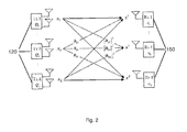
- Figure 2 depicts a schematic illustrating the nomenclature as used in the following.
- the base stations 120 of the system are considered as transmitters only, i.e. Tx1 ... Txk... TxK
- the mobile stations 150 are considered as receivers only, i.e. Rx1 ... Rxk ... RxK , wherein letter k is the index of a transmitter or a receiver with 1 ... k...K. Accordingly we consider a system comprising a number of K transmitter receiver pairs that share a common radio resource.
- Each transmitter aims at conveying a data stream to its associated receiver, wherein a transmission originating from the k -th transmitter to the k -th receiver interferes with transmissions of the other pairs of transmitters and receivers, at receivers 1 ... k-1 and k+1. .. K as illustrated by the transfer functions h.
- the k -th receiver thus observers a superposition of signals from all transmitters but is interested only in the transmit signal from its associated transmitter.
- index I shall denote any transmitter or receiver station not associated with the k -th transmitter station.
- each transmitter is shown with two transmit antennas, the system shall not be limited by this, i.e. a transmitter may comprise a plurality of at least two or more transmit antennas.
- each k -th pair of transmitter and associated receiver is assigned a user utility function u1 ... uk ... uK.
- the overall performance of the system can be evaluated by considering the sum of all assigned utility functions, i.e. by evaluating a system utility function U being the sum of all functions u k .
- Each user utility function u k shall have two properties
- Typical examples of user utility functions reflect the signal-to-interference-plus-noise ratio (SINR) at the receiver, the achievable information rate or the bit error rate.
- SINR signal-to-interference-plus-noise ratio
- beamforming vector i.e. the complex valued scalar antenna weights
- the parameter to be adjusted in order to optimize the overall system performance is the parameter to be adjusted in order to optimize the overall system performance.
- the k -th transmitter we define as optimization variable the power gain vector x k that comprises all receive powers at all of the receivers, i.e. at the K receivers. Accordingly the l -th component of vector x k is denoted as x k,l and reflects the received power at the l -th receiver caused by the k -th transmitter.
- the optimization of the overall system i.e. the optimization of the system utility function U shall be performed decentralized, i.e. distributed.
- said central processing entity has knowledge of all necessary information about the system, e.g. channel information, and that can solve the optimization problem.
- each transmitter participates in optimizing the system utility function, wherein it is assumed that each k -th transmitter has knowledge about the channels between itself, i.e. the k -th's transmitter and each receiver 1... K , as well as the channel strength between the k -th's receiver and each transmitter 1... K , and wherein the transmitters are communicatively coupled for mutual information exchange.
- this assumption is realized by receivers 1..k-1 , k+1...K, which report information reflecting channel state information to their respective associated base transmitter station. As described below said information is forwarded by the l -th base stations to the k -th base station, thus providing the channel state information between the k-th transmitter and the l-th receiver, i.e. receivers 1...k-1, k+1...K.
- an upper bound Tmax on the largest possible update interval i.e., the largest possible time span between two successive updates of the power gain vector x k
- an upper bound Dmax on the largest backhaul delay are known to all transmitters. Therefore, the time is indexed by a discrete variable n which indexes all event of interest (i.e., an update step, a transmission or reception of a message via backhaul). Note that this (global) time variable is only needed for illustration and analysis purposes.
- Each transmitter uses a gradient method to iteratively update his local optimization variable x k , i.e. his local power gain vector x k .
- Each iteration step aims at increasing the value of the system utility function U. Therefore, in each iteration performed at a transmitter the optimization variable x k is amended in the direction of the steepest increase of function U.
- the information regarding the steepest increase of system utility function U is given by the gradient vector of system utility function U with respect to the optimization variable, i.e. the optimization vector x k .
- the gradient vector of the k -th transmitter consists of the partial derivatives du 1 / dx k ,1 ,...,du k / dx k,k,..., du K / dx k,K .
- the components (i.e. partial derivatives) of this gradient vector must be computed by the individual transmitters, i.e. the l -th component of this gradient vector must be calculated by the l -th transmitter, and are exchanged thereafter between the transmitters. This is due to the local/exclusive knowledge of the individual transmitters, none of them has global knowledge. Only the l -th transmitter has the knowledge that is required for calculating the l -th component from the gradient vector of the k -transmitter. By selecting a system utility function that is differentiable, the partial derivatives can be calculated by using closed-form expressions.
- the components of the gradient vectors depend on the actual values of the optimization variable x 1 ,..., x k ,..., x K , i.e. the actual values of the power gain vectors that represent the current operating points of transmitters 1 ... K , these said gradient vector components have to be updated after each change in the optimization variables.
- the l -th transmitter needs the knowledge of all power gain vector components x 1,l ,... x K,l .
- the components of the optimization variables x 1 ... x k ... x K have to be mutually communicated from transmitter to transmitter, i.e. the k -th transmitter sends the l -th component x k,l of his power gain vector x k to the l -th transmitter. In this way each transmitter communicates each component of his power gain vector to the corresponding transmitter.
- the gradient vector components and the updated optimization values i.e. x 1 ... x k-1 , x k+1 ... x K , are real-valued scalars, so the transmitters exchange real valued scalars.
- the amount of data to be communicated between the transmitters via the backhaul link is small, thus supporting a fast and effective implementation of the method and preventing clogging of the backhaul communication link.
- FIG. 3 illustrates the method steps 300 iteratively performed by each transmitter at some arbitrary intervals and speed.
- all transmitters may keep radiating their signals (i.e. their transport streams) all the time, independently from the optimization process. From time to time, they may adapt their radiation by applying the new antenna weight vector that has been obtained from the (parallel ongoing) optimization process. Such an adaptation will yield an increased system utility.
- the following method steps are described from the viewpoint of the k -th transmitter that radiates a signal, wherein said radiated signal is received by the k- th receiver, i.e. the receiver associated with the radiating transmitter and by receivers 1...k-1 as well as receivers k+1...K , i.e. receivers associated with transmitters 1...l ... k-1 and k+1 ... K of cells adjoining the k -th cell.
- the first method step right after start 310 is the selection by at least the k -th transmitter of an initial gain vector x k in step 320.
- the k-th transmitter transfers all components l ⁇ k of the (current) power gain vector x k to the respective l- th transmitter.
- step 360 the k -th transmitter, i.e. each considered transmitter, transmits for each l ⁇ k, the calculated partial derivative du k / dx l,k to the respective l -th transmitter, i.e. to each other of the considered transmitters, via the backhaul link.
- step 370 i.e. when the k -th transmitter has received the partial derivatives du l / dx k,l of all other transmitters I, the transmitter updates his power gain vector x k . This update computation is described below.
- the transmitter checks in step 380 whether the algorithm converged. Depending on the largest possible backhaul communication delay Dmax and the largest possible inter-update interval Tmax, that is used by any transmitter in the network, the k -th transmitter checks whether the difference between its new calculated power gain vector and its power gain vector from (Dmax+Tmax) time instants before is smaller than a pre-specified threshold.
- the transmitter continues to use the antenna weights that have been calculated with respect to the latest power gain vector x k , and the loop ends, in block 390.
- step 330 i.e. the k -th transmitter transfers all components l ⁇ k of the power gain vector x k , obtained in step 370, to the respective l -th transmitter
- the k -th transmitter iterates (in arbitrary intervals, i.e. solely limited by the maximum inter-update period) through a loop until the algorithm converges, i.e. until the system utility function converges.
- step 370 the k -th transmitter may update his individual power gain vector x k before it has received the most recent partial derivatives.
- step 350 the transmitter may calculate the partial derivatives before it has received the most recent power gain components.
- the transmitter may perform computations based on outdated information. Some transmitters may perform their computations faster than others. The transmitters do not need to communicate to each other at each time instant thus they may exchange information at arbitrary intervals and operate asynchronously.
- the k -th transmitter adapts the components of vector x k one step in the direction of the gradient vector. Since the k -th transmitter does not have the information about the system utility function, the k -th transmitter cannot determine the optimal step size for the current update step, i.e. the k -th transmitter cannot determine the step size which provides the highest increase of the system utility function. To prevent an overshoot, i.e. due to a step size too large, the step size must be limited, wherein said limitation of the step size ensures that the system utility function always increases.
- the second derivative is finite for all relevant operation points. Furthermore we consider the delays in communication between the transmitters when communicating the power gain components/partial derivatives, and we consider the absolute value of the second (partial) derivative of the system utility function.
- the determination of the upper limit for the step size is determined as follows. Initially a function is defined that shall serve as the lower limit for the system utility function. For that purpose, a Taylor polynomial of second order using limits of the second partial derivatives is defined. Subsequently an error term is introduced into that function, which reflects the update step error caused by the use of outdated gradients.
- the error term is then approximated under deployment of the finite limits of the communication delays and the second-order partial derivatives, while ensuring that the resulting function is a valid lower limit for the system utility function.
- the algorithm uses defined step sizes and allows especially parallel, i.e. simultaneous, updating of all considered transmitters. Note that this is also true in case the transmitters operate on outdated information (i.e., power gains and partial derivatives) transmitted from other transmitters. As a consequence each transmitter may update his power gain values based on the available information provided by other transmitters, i.e. the transmitters may operate asynchronously.
- the beamforming vectors i.e. the antenna weights
- the antenna weights can be calculated based on the power gain vectors. Similar as in our considerations above, it is sufficient to consider the k -th transmitter only for reasons of symmetry.
- the optimization domain that is, the domain of the power gain vectors that are used as optimization variables.
- the optimization domain (i.e. the feasible set of power gain vectors) of the k -th transmitter is given by the power gain region ⁇ k .
- the power gain area as depicted in the figure is two-dimensional. Note that figure 4 depicts two particular operating points, i.e. two particular power gain vectors:
- the area of the power gain is defined by the entity of transmitter correlation matrices being positive semi-definite and having a trace ⁇ 1. This last condition limits the maximum transmission power to 1. Accordingly for generating the power gain area, correlation matrices of arbitrary rank have been used. Consequently, the entity of ⁇ k is convex, which is required for projecting an updated power gain vector x k back to its valid range (i.e. constraint set), performed in step 370. Considering now that the transmitter always uses only a beamforming vector (i.e. antenna weight vector) for its radiation, then the corresponding correlation matrix is always of rank ⁇ 1.
- a beamforming vector i.e. antenna weight vector
- the power gain area may comprise operating points, which are not reachable by correlation matrices of rank 1, that is, it may contain power gain vectors that are not achievable by using beamforming vectors.
- all power gain vectors relevant for the sum utility problem i.e. the stationary operating points of our optimization problem, can be reached with correlation matrices of rank 1.
- ⁇ k which has been retrieved by relaxing the matrix rank, for the projection in step 370; wherein it is known that the power gain vector, which is obtained when the algorithm 300 has converged, is reachable by a beamforming vector.
- step 370 Before we can describe how to calculate the k-th beamforming vector based on the power gain vector, we have to illustrate a single update step as performed in step 370. More precisely, we have to illustrate the projection step performed within step 370.
- this projection problem can NOT be solved by the entity of power gain vectors, i.e. this is not solvable in the power gain domain since it is unknown a priori which vectors belong to entity ⁇ k ; this can only be solved by try and error.
- said problem can be solved optimally using the entity of all signal correlation matrices; as noted above the entity of all possible signal correlation matrices defines the power gain area.
- the cost function of the projection problem i.e.
- the scaled Euclidian distance between vector x k ( n )+ ⁇ k M k -1 ⁇ k ( n ) and any reachable point of entity ⁇ k is reformulated using correlation matrix Q as the optimization variable for the projection problem, that leads to an equivalent convex optimization problem.
- Said optimization problem is a quadratic semi-definite optimization problem that can be solved by mathematical conventional tools, e.g. QSDP-0 for Matlab.
- Q *( n +1) generates the sought-after power gain vector x k ( n +1,) i.e. the power gain vector that is the solution of update step 370.
- matrix Q *( n +1) is of rank ⁇ 2.
- matrix Q *( n +1) is of rank ⁇ 2.
- a beamforming vector generating at least the same sum utility.
- the user utility function u k being monotonous, it is sufficient to look for beamforming vectors causing less or the same amount of interference, and which generate at least the same load gain.
- we constrain to solutions, i.e. beamforming vectors, having a particular phase shift, namely the load signal, received by the intended receiver, that is given by h kk H w k must be real valued. Note that the optimum solution does not suffer from the phase shift, i.e. the phase shift does not influence the power gains.
Landscapes
- Engineering & Computer Science (AREA)
- Signal Processing (AREA)
- Computer Networks & Wireless Communication (AREA)
- Power Engineering (AREA)
- Quality & Reliability (AREA)
- Mobile Radio Communication Systems (AREA)
Abstract
Description
- The invention relates to a telecommunication system comprising a plurality of communicatively coupled radio transmitter stations, wherein the radio transmitter stations are configured for exchanging information via a backhaul link to reduce intercell interference.
- Mobile communication systems, also known as cellular telecommunication systems, typically comprise a plurality of adjoining communication cells, wherein each cell is determined by the radio range of the stationary transceiver station. Stationary transceiver stations are known as base stations in the early mobile telecommunication systems such as GSM or GPRS or as eNodeB in the UMTS or as access points in wireless LAN systems. In the following the stationary transceiver stations are called base stations. Each cell, i.e. the base station within a cell, may serve a plurality of mobile stations by providing a radio link for up- and downlink communication, wherein a mobile station can be a cell phone or a so-called smartphone or any other device capable of exchanging information via the radio link with the base station. Though the devices actually may be mobile or non-mobile, i.e. geographically fixed, the following description deploys the term mobile device. Note that the invention shall not be limited to any particular hardware or radio communication protocol.
- When a base station transmits information to a mobile station, i.e. downlink communication, the base station typically does not radiate the signal with its maximum power. Instead the radiation parameters including radiation power are adapted according to the channel properties. However, at the receiving mobile station the signal from the base station is received with interference, i.e. the received signal is a superposition of a plurality of signals, i.e. the received signal comprises the desired signal as well as interfering signals of a plurality of sources.
- In particular mobile stations located at the borderline of a cell will suffer from signals radiated by the at least one adjacent cell, since the radio range of each cell overlaps adjacent cells depending on the transmission power of the base stations. Accordingly the mobile station located at an edge of a cell will suffer from so-called inter cell interference upon reception, since radio signals radiated by base stations of adjoining cells interfere, i.e. superpose, with signals radiated by the base station currently associated with the mobile station.
- To mitigate these adverse effects of inter cell interference it has been proposed to optimize the radiations by beamforming based on information exchange between base stations of adjoining cells. By directing the radiation beam of a base station to an associated and intended mobile station the interference to other mobile stations caused by that radiation can be reduced. In this way the overall performance of the system may be improved by reducing inter cell interference. However, the optimization may require several iterations of beamformer adaptation and information exchange. Since conventional systems suffer from communication delays caused by transmission delays in the connecting backhaul link, the entire optimization process is slowed down. Further, existing optimization schemes cannot tolerate concurrent beamformer adaptations; that is, the base stations have to accomplish their adaptations in a sequential fashion. Consequently, conventional systems require a synchronization mechanism for their optimization process. Hence it is an object of the invention to at least mitigate these problems, i.e. to speed-up this optimization process and to enable an optimization process in networks without any synchronization mechanisms.
- These as well as other features of the present invention will become apparent to those of ordinary skill in the art by reading the following description with appropriate reference to the accompanying drawings of an embodiment. However, the invention shall not be limited to below described embodiment.
- Reference is made to the accompanying figures wherein
- Fig. 1
- depicts a diagram of a cellular telecommunication system;
- Fig. 2
- depicts a MISO scheme according to the invention;
- Fig. 3
- depicts a flow chart of a proposed optimization method;
- Figs. 4
- depict scheme for projecting an updated optimization variable back to the feasible (i.e., constraint) set.
-
Figure 1 depicts a diagram of acellular communication system 100 comprising a plurality of adjoiningcells 110a-110. Each cell comprises abase station 120a-120c that provides a radio interface to mobile stations residing in the cell, i.e. the mobile stations are associated with the base station.Mobile station 150a may reside incell 110a and may be associated withbase station 120a andmobile stations respective base station respective cell - A
mobile station 150 can be any electronic device capable of exchanging information via the radio interface provided by the base station of a cell, i.e. a mobile station can be a cellular mobile phone, a so-called smartphone, a tablet or laptop computer or any other stationary or mobile device capable of exchanging, particularly receiving, information via the radio link, wherein the device may deploy one effective receive antenna. However, in case the receiver comprises a plurality of receive antennas, we assume that these are deployed for receiving a single transport stream at a time, i.e. the receiver may deploy a combining, e.g. a maximum ratio combining, to receive the single transport stream. Thus the multiple antennas of a mobile station are considered as one effective antenna. - In one embodiment the base stations form part of a radio access network, a so-called RAN, of a cellular telecommunications network. The base stations are communicatively coupled by reliable, typically but not necessarily, wired communication links 130, wherein said communication links may couple the respective base station to
other nodes 140, e.g. base station controllers or SGSNs, of the radio access network.Base stations 120 of at least adjoining cells in this way are communicatively coupled for information exchange either viabridging nodes 140 or directly, i.e. without any bridging node (not shown in the figure). The information exchange between base stations that are not directly coupled, relies on message forwarding by other base stations. Subsequently the communication network enables the information exchange between all base stations is denoted as backhaul link. - As briefly noted above the geographical areas of the radio cells 110 overlap, i.e. radiation emitted by a base station does not stop at the edge of an adjacent radio cell. Even if beamforming is used to (egoistically) improve the radiation to the direction of the intended receiving mobile station, the radiated signal will propagate beyond the current location of the intended receiving mobile station. So even if
base station 120c radiates asignal 160c that is intended formobile station 150c and whereinbase station 120c has applied a beamforming, said signal will propagate into adjoiningcells mobile station 150b, becausebase station 120c radiates using the same radio resources as used in the adjoining cell, i.e. the transmission incell 120c occurs on the same frequency while amobile station 150b incell 110b receives a transmission from itsassociated base station 120b. - Each
base station 120 comprises a plurality of at least two transmit antennas and is capable of controlling the direction of radiation, i.e. the base station is capable of so-called beamforming when transmitting. Each base station, i.e. considered here as a transmitter, may control the beamforming by applying a complex valued scalar antenna weight to each of it's transmit antennas. The set of all antenna weights of one transmitter thus may form a beamforming vector of said transmitter. A base station thus may control the geographical radiation pattern when transmitting. In one embodiment this can be achieved by a beamformer control that controls the phase and relative amplitude of the signal transmitted by each antenna of the plurality of transmit antennas in order to create a pattern of constructive and destructive interference in the wavefront at the location of the intended receiver, i.e. at the intended mobile station. In this way the beamforming vector of controls the spatial distribution of a radiated signal. -
Figure 2 depicts a schematic illustrating the nomenclature as used in the following. Thebase stations 120 of the system are considered as transmitters only, i.e. Tx1 ... Txk... TxK , themobile stations 150 are considered as receivers only, i.e. Rx1...Rxk...RxK, wherein letter k is the index of a transmitter or a receiver with 1... k...K. Accordingly we consider a system comprising a number of K transmitter receiver pairs that share a common radio resource. Each transmitter aims at conveying a data stream to its associated receiver, wherein a transmission originating from the k-th transmitter to the k-th receiver interferes with transmissions of the other pairs of transmitters and receivers, atreceivers 1... k-1 and k+1...K as illustrated by the transfer functions h. The k-th receiver thus observers a superposition of signals from all transmitters but is interested only in the transmit signal from its associated transmitter. Note that index I shall denote any transmitter or receiver station not associated with the k-th transmitter station. Though each transmitter is shown with two transmit antennas, the system shall not be limited by this, i.e. a transmitter may comprise a plurality of at least two or more transmit antennas. - To optimize the transmissions from a base station, i.e. to optimize the beamforming vector of a transmitter, to an associated receiver, each k-th pair of transmitter and associated receiver is assigned a user utility function u1 ... uk ... uK. The overall performance of the system can be evaluated by considering the sum of all assigned utility functions, i.e. by evaluating a system utility function Ubeing the sum of all functions uk . Each user utility function uk shall have two properties
- 1. uk is strictly monotonically increasing with respect to the intended (useful) signal power, i.e. receive signal power at the k-th receiver from its associated k-th transmitter,
- 2. uk is strictly monotonically decreasing with respect to the interference power, i.e. with respect to the receive signal power at the k-th receiver caused by all transmitters l≠k.
- Typical examples of user utility functions reflect the signal-to-interference-plus-noise ratio (SINR) at the receiver, the achievable information rate or the bit error rate.
- Above mentioned beamforming vector, i.e. the complex valued scalar antenna weights, of a transmitter is the parameter to be adjusted in order to optimize the overall system performance.
- However, it is not the beamforming vector that is considered for optimizing a best system performance (e.g. throughput). Instead the resulting power gains are considered as variables to be optimized. Hence, for the k-th transmitter we define as optimization variable the power gain vector xk that comprises all receive powers at all of the receivers, i.e. at the K receivers. Accordingly the l-th component of vector xk is denoted as xk,l and reflects the received power at the l-th receiver caused by the k-th transmitter.
- Furthermore the optimization of the overall system, i.e. the optimization of the system utility function U shall be performed decentralized, i.e. distributed. As a consequence there is no central processing entity for solving said optimization problem, wherein said central processing entity has knowledge of all necessary information about the system, e.g. channel information, and that can solve the optimization problem.
- Instead it is assumed, that each transmitter participates in optimizing the system utility function, wherein it is assumed that each k-th transmitter has knowledge about the channels between itself, i.e. the k-th's transmitter and each
receiver 1...K, as well as the channel strength between the k-th's receiver and eachtransmitter 1...K, and wherein the transmitters are communicatively coupled for mutual information exchange. In real life this assumption is realized byreceivers 1..k-1, k+1...K, which report information reflecting channel state information to their respective associated base transmitter station. As described below said information is forwarded by the l-th base stations to the k-th base station, thus providing the channel state information between the k-th transmitter and the l-th receiver, i.e.receivers 1...k-1, k+1...K. - Furthermore, an upper bound Tmax on the largest possible update interval (i.e., the largest possible time span between two successive updates of the power gain vector xk ), as well as an upper bound Dmax on the largest backhaul delay are known to all transmitters. Therefore, the time is indexed by a discrete variable n which indexes all event of interest (i.e., an update step, a transmission or reception of a message via backhaul). Note that this (global) time variable is only needed for illustration and analysis purposes.
- Each transmitter uses a gradient method to iteratively update his local optimization variable xk , i.e. his local power gain vector xk . Each iteration step aims at increasing the value of the system utility function U. Therefore, in each iteration performed at a transmitter the optimization variable xk is amended in the direction of the steepest increase of function U. For the k-th transmitter the information regarding the steepest increase of system utility function U is given by the gradient vector of system utility function U with respect to the optimization variable, i.e. the optimization vector xk . The gradient vector of the k-th transmitter consists of the partial derivatives du 1/dx k,1 ,...,duk /dxk,k,..., duK /dxk,K. The components (i.e. partial derivatives) of this gradient vector must be computed by the individual transmitters, i.e. the l-th component of this gradient vector must be calculated by the l-th transmitter, and are exchanged thereafter between the transmitters. This is due to the local/exclusive knowledge of the individual transmitters, none of them has global knowledge. Only the l-th transmitter has the knowledge that is required for calculating the l-th component from the gradient vector of the k-transmitter. By selecting a system utility function that is differentiable, the partial derivatives can be calculated by using closed-form expressions.
- As the components of the gradient vectors depend on the actual values of the optimization variable x1 ,..., xk ,...,xK , i.e. the actual values of the power gain vectors that represent the current operating points of
transmitters 1...K, these said gradient vector components have to be updated after each change in the optimization variables. In other words, in order compute the l-th component for the gradient vector of the k-th transmitter, the l-th transmitter needs the knowledge of all power gain vector components x1,l ,...xK,l . - Since only the k-th transmitter (due to his local knowledge) is able to calculate all components of its optimization variable xk (i.e., x k1,...,xkK ), the components of the optimization variables x1 ...xk ...xK have to be mutually communicated from transmitter to transmitter, i.e. the k-th transmitter sends the l-th component xk,l of his power gain vector xk to the l-th transmitter. In this way each transmitter communicates each component of his power gain vector to the corresponding transmitter.
- Note that the gradient vector components and the updated optimization values, i.e. x1 ...xk-1 , xk+1 ...xK , are real-valued scalars, so the transmitters exchange real valued scalars. As a consequence the amount of data to be communicated between the transmitters via the backhaul link is small, thus supporting a fast and effective implementation of the method and preventing clogging of the backhaul communication link.
-
Figure 3 illustrates the method steps 300 iteratively performed by each transmitter at some arbitrary intervals and speed. Note that, all transmitters may keep radiating their signals (i.e. their transport streams) all the time, independently from the optimization process. From time to time, they may adapt their radiation by applying the new antenna weight vector that has been obtained from the (parallel ongoing) optimization process. Such an adaptation will yield an increased system utility. - The following method steps are described from the viewpoint of the k-th transmitter that radiates a signal, wherein said radiated signal is received by the k-th receiver, i.e. the receiver associated with the radiating transmitter and by
receivers 1...k-1 as well as receivers k+1...K, i.e. receivers associated withtransmitters 1...l... k-1 and k+1...K of cells adjoining the k-th cell. - The first method step right after
start 310 is the selection by at least the k-th transmitter of an initial gain vector xk instep 320. Instep 330 the k-th transmitter transfers all components l≠k of the (current) power gain vector xk to the respective l-th transmitter. - At
step 340, at least the k-th transmitter calculates a new antenna weight vector wk based on the current power gain vector xk , wherein the current power gain vector in the first iteration of the loop is that of the initial selection ofstep 320. Otherwise, i.e. in each subsequent loop iteration the k-th transmitter calculates the antenna weight vector based on a gain vector updated in a previous loop iteration, confer belowstep 370. The k-th transmitter then adapts (its steadily ongoing) signal radiation by using the calculated antenna weight vector wk. - Based on the power gain components xl,k , for l=1,...,K,received via backhaul link, the k-th transmitter calculates in
step 350 the new partial derivatives duk /dxl,k of his user utility function uk with respect to the received power gains xl,k of all considered transmitters l=1,...,K. Due to the differentiability of the utility functions, there exist closed-form expressions for the partial derivatives. - In
step 360 the k-th transmitter, i.e. each considered transmitter, transmits for each l≠k, the calculated partial derivative duk /dxl,k to the respective l-th transmitter, i.e. to each other of the considered transmitters, via the backhaul link. - In
step 370, i.e. when the k-th transmitter has received the partial derivatives dul /dxk,l of all other transmitters I, the transmitter updates his power gain vector xk. This update computation is described below. - The transmitter then checks in
step 380 whether the algorithm converged. Depending on the largest possible backhaul communication delay Dmax and the largest possible inter-update interval Tmax, that is used by any transmitter in the network, the k-th transmitter checks whether the difference between its new calculated power gain vector and its power gain vector from (Dmax+Tmax) time instants before is smaller than a pre-specified threshold. - If the algorithm converged, then the transmitter continues to use the antenna weights that have been calculated with respect to the latest power gain vector xk , and the loop ends, in
block 390. - Otherwise, i.e. in case the transmitter detects that the algorithm has not converged, the iteration loop continues with performing
step 330, i.e. the k-th transmitter transfers all components l≠k of the power gain vector xk , obtained instep 370, to the respective l-th transmitter - In this way the k-th transmitter iterates (in arbitrary intervals, i.e. solely limited by the maximum inter-update period) through a loop until the algorithm converges, i.e. until the system utility function converges.
- Note that in
step 370 the k-th transmitter may update his individual power gain vector xk before it has received the most recent partial derivatives. The same holds forstep 350, where the transmitter may calculate the partial derivatives before it has received the most recent power gain components. In other words, the transmitter may perform computations based on outdated information. Some transmitters may perform their computations faster than others. The transmitters do not need to communicate to each other at each time instant thus they may exchange information at arbitrary intervals and operate asynchronously. - A few remarks concerning the update computation in step 370: The k-th transmitter adapts the components of vector xk one step in the direction of the gradient vector. Since the k-th transmitter does not have the information about the system utility function, the k-th transmitter cannot determine the optimal step size for the current update step, i.e. the k-th transmitter cannot determine the step size which provides the highest increase of the system utility function. To prevent an overshoot, i.e. due to a step size too large, the step size must be limited, wherein said limitation of the step size ensures that the system utility function always increases.
- This is accomplished by selecting a system utility function that is twice differentiable, i.e. the second derivative is finite for all relevant operation points. Furthermore we consider the delays in communication between the transmitters when communicating the power gain components/partial derivatives, and we consider the absolute value of the second (partial) derivative of the system utility function. The determination of the upper limit for the step size is determined as follows. Initially a function is defined that shall serve as the lower limit for the system utility function. For that purpose, a Taylor polynomial of second order using limits of the second partial derivatives is defined. Subsequently an error term is introduced into that function, which reflects the update step error caused by the use of outdated gradients. The error term is then approximated under deployment of the finite limits of the communication delays and the second-order partial derivatives, while ensuring that the resulting function is a valid lower limit for the system utility function. Some mathematical conversions yield to a quadratic function that allows calculation of a step size limit which under all circumstances guarantees an increase of the quadratic function. Considering now that said quadratic function is a lower bound for the system utility function, it follows that said system utility function necessarily must increase.
- Accordingly the algorithm uses defined step sizes and allows especially parallel, i.e. simultaneous, updating of all considered transmitters. Note that this is also true in case the transmitters operate on outdated information (i.e., power gains and partial derivatives) transmitted from other transmitters. As a consequence each transmitter may update his power gain values based on the available information provided by other transmitters, i.e. the transmitters may operate asynchronously.
- As mentioned above the beamforming vectors, i.e. the antenna weights, can be calculated based on the power gain vectors. Similar as in our considerations above, it is sufficient to consider the k-th transmitter only for reasons of symmetry.
- Before we can calculate the k-th beamforming vector based on the power gain vector, we describe the optimization domain, that is, the domain of the power gain vectors that are used as optimization variables.
- The optimization domain (i.e. the feasible set of power gain vectors) of the k-th transmitter is given by the power gain region Ω k. Let Ω k be the entirety of all possible power gain vectors xk , which transmitter k may generate by radiating a signal sk using a transmitter correlation matrix Q=E{sksk H}.
Figure 4a depicts an illustration of the power gain region Ω k for a Multiple-In-Single-Out interference channel, i.e. MISO IFC, with K=2 transmitters, i.e. users. The figure depicts a power gain area Ω1 for transmitter k=1. Since the system comprises two transmitters, i.e. users, only, the power gain vector of user k=1, i.e. x1 , will have two components, wherein x1,1 is the power gain, i.e. load power (=useful signal power), to the associated receiver k=1 and x1,2 is the interfering power gain received at receiver k=2. Hence the power gain area as depicted in the figure is two-dimensional. Note thatfigure 4 depicts two particular operating points, i.e. two particular power gain vectors: - x1 MRT denotes the egoistic working point x1 MRT (MRT=Maximum Ratio Transmission), where
transmitter 1 maximizes its load power x1,1 and where any possible interference at receiver k=2 is ignored; - x1 ZF (ZF=Zero Force) is the altruistic working point, where transmitter k=1 does not produce any interference x1,2 at receiver k=2, i.e. transmitter k=1 takes what is left.
- Note that the area of the power gain is defined by the entity of transmitter correlation matrices being positive semi-definite and having a
trace ≤ 1. This last condition limits the maximum transmission power to 1. Accordingly for generating the power gain area, correlation matrices of arbitrary rank have been used. Consequently, the entity of Ω k is convex, which is required for projecting an updated power gain vector xk back to its valid range (i.e. constraint set), performed instep 370. Considering now that the transmitter always uses only a beamforming vector (i.e. antenna weight vector) for its radiation, then the corresponding correlation matrix is always of rank ≤ 1. As a consequence the power gain area may comprise operating points, which are not reachable by correlation matrices ofrank 1, that is, it may contain power gain vectors that are not achievable by using beamforming vectors. However, it can be demonstrated that all power gain vectors relevant for the sum utility problem, i.e. the stationary operating points of our optimization problem, can be reached with correlation matrices ofrank 1. As a consequence, we exploit the convexity of Ω k , which has been retrieved by relaxing the matrix rank, for the projection instep 370; wherein it is known that the power gain vector, which is obtained when thealgorithm 300 has converged, is reachable by a beamforming vector. - Before we can describe how to calculate the k-th beamforming vector based on the power gain vector, we have to illustrate a single update step as performed in
step 370. More precisely, we have to illustrate the projection step performed withinstep 370. - For that purpose we consider, that the k-th transmitter performed an update of his power gain vector xk at time index n. For that a projection, additionally scaled by matrix Mk , of vector xk (n)+γ kM k -1 λ k (n) onto the convex compact entity of Ω k is required, confer
figure 4b . Note that the vector λ k (n) denotes the vector of all acquired partial derivatives. - Due to the mathematical structure of the power gain region this projection problem can NOT be solved by the entity of power gain vectors, i.e. this is not solvable in the power gain domain since it is unknown a priori which vectors belong to entity Ω k ; this can only be solved by try and error. However, said problem can be solved optimally using the entity of all signal correlation matrices; as noted above the entity of all possible signal correlation matrices defines the power gain area. For that purpose the cost function of the projection problem, i.e. the scaled Euclidian distance between vector xk (n)+γ kMk -1 λ k (n) and any reachable point of entity Ω k , is reformulated using correlation matrix Q as the optimization variable for the projection problem, that leads to an equivalent convex optimization problem. Said optimization problem is a quadratic semi-definite optimization problem that can be solved by mathematical conventional tools, e.g. QSDP-0 for Matlab. The solution of said optimization problem, named Q*(n+1) generates the sought-after power gain vector xk (n+1,) i.e. the power gain vector that is the solution of
update step 370. - Based on Q*(n+1) for time (n+1) a corresponding beamforming vector can be found for the next radiation. Still, there are two problems. We know, 1st, that power gain vectors associated with stationary points of the optimization problem can be reached by beamforming, i.e. a
rank 1 correlation matrix, but that is not true for the power gain vectors that arise during the optimization process (i.e. when thealgorithm 300 has not yet converged). And, 2nd, if matrix Q*(n+1) is of rank ≥2, the corresponding beamforming vector cannot be easily extracted, because the corresponding optimization problem is not convex, even if we know in theory that the associated power gain vector is reachable withrank 1. - Therefore a case-by-case analysis can be made. In the first case matrix Q*(n+1) is of
rank 1, which practically is almost true for real life. Then we have to find the dominant eigenvector of said matrix and weight that by the square root of his greatest eigenvalue. That beamforming vector exactly generates the same power gain vector xk (n+1), i.e. the power gain vector for the transmission in the iteration loop offigure 3 . - Otherwise, in the second case, matrix Q*(n+1) is of rank ≥2. In this case we search for a beamforming vector generating at least the same sum utility. As we consider the user utility function uk being monotonous, it is sufficient to look for beamforming vectors causing less or the same amount of interference, and which generate at least the same load gain. In order to get this mathematical problem convex, we constrain to solutions, i.e. beamforming vectors, having a particular phase shift, namely the load signal, received by the intended receiver, that is given by hkk Hwk , must be real valued. Note that the optimum solution does not suffer from the phase shift, i.e. the phase shift does not influence the power gains.
Claims (14)
- Cellular telecommunication system comprising a plurality 1...l, k...K of coupled radio transmitter stations communicatively coupled via a backhaul link and arranged in adjoining radio cells 1...l, k...K,
at least the k-th radio transmitter station being capable of beamforming a radiated signal by controlling an antenna weights vector, and wherein the at least k-th radio transmitter station is adapted for iterating the steps of:- calculating an antenna weights vector based on the k-th transmit power gain vector and transmitting a radio signal using the calculated antenna weights, and- computing partial derivatives based on the components of power gain vector components received via the backhaul link from at least one l-th radio transmitter station, and- transmit via the backhaul link at least the l-th partial derivative of its utility function to the l-th radio transmitter station, and- updating the k-th power gain vector based on the partial derivatives received from the at least l-th radio transmitter, and- transmitting at least the l-th component of the k-th power gain vector to the l-th radio transmitter station. - Cellular telecommunication system according to claim 1 wherein- the k-th radio base station and the l-th radio base station are further adapted to asynchronously exchange partial derivatives and power gains.
- Cellular telecommunication system according to any preceding claim wherein the step of updating the k-th power gain vector is based on a defined step size that ensures convergence to a stationary point of the system utility function, said utility function reflecting at least one of the signal-to-interference-plus noise ratio or the achievable information rate or the bit error rate.
- Cellular telecommunication system according to any preceding claim wherein the radio transmitter stations are base stations of a cellular telecommunication network communicatively coupled by a radio access network of the cellular telecommunication network.
- Cellular telecommunication system according to any preceding claim wherein at least a k-th receiver is associated with the k-th radio transmitter station and an l-th receiver is associated with the l-th radio transmitter station, wherein at least the l-th receiver is adapted to communicate to the l-th radio transmitter station the receive power of the signal radiated by the k-th radio transmitter station.
- Cellular telecommunication system according to any preceding claim wherein at least the k-th transmitter station is further adapted to perform the steps in a loop.
- Cellular telecommunication system according to any preceding claim wherein at least the k-th transmitter station is adapted to update his individual power gain vector before receiving the most recent partial derivative from the l-th transmitter station.
- Cellular telecommunication system according to any preceding claim wherein at least the k-th transmitter station is adapted to calculate the partial derivatives before receiving the l-th most recent power gain vector components.
- A method for optimizing data transmission in a cellular telecommunication system, said system comprising a plurality of plurality 1...l, k...K of coupled radio transmitter stations communicatively coupled via a backhaul link and arranged in adjoining radio cells 1...l, k...K, at least the k-th radio transmitter station being capable of beamforming a radiated signal by controlling an antenna weights vector, and wherein at least k-th radio transmitter station is adapted for iterating the steps of:- calculating an antenna weights vector based on the k-th transmit power gain vector and transmitting a radio signal using the calculated antenna weights vector, and- computing partial derivatives based on the power gain vector components received via the backhaul link from at least one l-th radio transmitter station, and- transmit via the backhaul link at least the l-th partial derivative of its utility function to the l-th radio transmitter station, and- updating the k-th power gain vector based on the partial derivatives received from the at least l-th radio transmitter, and- transmitting at least the l-th component of the k-th power gain vector to the l-th radio transmitter station.
- The method according to claim 9 wherein the k-th radio base station and the l-th radio base station are further adapted to asynchronously exchange partial derivatives and power gains.
- The method according to any of claims 9-10 wherein the step of updating the k-th power gain vector is based on a defined step size that ensures convergence to a stationary point of the system utility function.
- The method according to any of claims 9-11 wherein the radio transmitter stations are base stations of a cellular telecommunication network communicatively coupled by a radio access network of the cellular telecommunication network.
- The method according to any of claims 9-12 wherein the method steps are performed in a loop.
- The method according to any of claims 9-13 wherein the k-th transmitter station updates its power gain vector before receiving the most recent partial derivative from the l-th transmitter station and the k-th transmitter calculates the partial derivatives before receiving the l-th most recent power gain vector components.
Priority Applications (2)
| Application Number | Priority Date | Filing Date | Title |
|---|---|---|---|
| EP14163758.7A EP2930858B1 (en) | 2014-04-07 | 2014-04-07 | Telecommunication system and method using distributed asynchronous beamforming in the MISO interference channel |
| US14/680,691 US9516649B2 (en) | 2014-04-07 | 2015-04-07 | Telecommunication system and method using distributed asynchronous beamforming in the MISO interference channel |
Applications Claiming Priority (1)
| Application Number | Priority Date | Filing Date | Title |
|---|---|---|---|
| EP14163758.7A EP2930858B1 (en) | 2014-04-07 | 2014-04-07 | Telecommunication system and method using distributed asynchronous beamforming in the MISO interference channel |
Publications (2)
| Publication Number | Publication Date |
|---|---|
| EP2930858A1 true EP2930858A1 (en) | 2015-10-14 |
| EP2930858B1 EP2930858B1 (en) | 2017-06-21 |
Family
ID=50440540
Family Applications (1)
| Application Number | Title | Priority Date | Filing Date |
|---|---|---|---|
| EP14163758.7A Active EP2930858B1 (en) | 2014-04-07 | 2014-04-07 | Telecommunication system and method using distributed asynchronous beamforming in the MISO interference channel |
Country Status (2)
| Country | Link |
|---|---|
| US (1) | US9516649B2 (en) |
| EP (1) | EP2930858B1 (en) |
Families Citing this family (2)
| Publication number | Priority date | Publication date | Assignee | Title |
|---|---|---|---|---|
| KR102188306B1 (en) * | 2014-09-02 | 2020-12-08 | 삼성전자주식회사 | A method and apparatus for transmitting packet in a communication system |
| JP7375035B2 (en) * | 2019-03-13 | 2023-11-07 | ノキア テクノロジーズ オサケユイチア | Devices, methods and computer readable media for adjusting beamforming profiles |
Family Cites Families (3)
| Publication number | Priority date | Publication date | Assignee | Title |
|---|---|---|---|---|
| US6956907B2 (en) * | 2001-10-15 | 2005-10-18 | Qualcomm, Incorporated | Method and apparatus for determining power allocation in a MIMO communication system |
| KR100946930B1 (en) * | 2006-07-31 | 2010-03-09 | 삼성전자주식회사 | Method and apparatus for controlling transmit antenna gain in communication system |
| US8193975B2 (en) * | 2008-11-12 | 2012-06-05 | Atc Technologies | Iterative antenna beam forming systems/methods |
-
2014
- 2014-04-07 EP EP14163758.7A patent/EP2930858B1/en active Active
-
2015
- 2015-04-07 US US14/680,691 patent/US9516649B2/en active Active
Non-Patent Citations (2)
| Title |
|---|
| RUI ZHANG ET AL: "Cooperative Interference Management With MISO Beamforming", IEEE TRANSACTIONS ON SIGNAL PROCESSING, IEEE SERVICE CENTER, NEW YORK, NY, US, vol. 58, no. 10, 1 October 2010 (2010-10-01), pages 5450 - 5458, XP011312572, ISSN: 1053-587X * |
| SCHMIDT D ET AL: "Distributed resource allocation schemes", IEEE SIGNAL PROCESSING MAGAZINE, IEEE SERVICE CENTER, PISCATAWAY, NJ, US, vol. 26, no. 5, 1 September 2009 (2009-09-01), pages 53 - 63, XP011276077, ISSN: 1053-5888, DOI: 10.1109/MSRP.2009.933371 * |
Also Published As
| Publication number | Publication date |
|---|---|
| US20150289248A1 (en) | 2015-10-08 |
| US9516649B2 (en) | 2016-12-06 |
| EP2930858B1 (en) | 2017-06-21 |
Similar Documents
| Publication | Publication Date | Title |
|---|---|---|
| CN109891963B (en) | System and method for beamformed reference signals in a three-dimensional multiple-input multiple-output communication system | |
| US12028139B2 (en) | Wireless telecommunications network including a multi-layer transmissive reconfigurable intelligent surface | |
| US8630677B2 (en) | Distributed beam selection for cellular communication | |
| CN110048749B (en) | Multiple-input multiple-output training method and wireless device | |
| US9743397B2 (en) | Reduced-size message pass in factor graphs for wireless communications networks | |
| US20220338025A1 (en) | Methods and apparatuses for receiving and sending reference signal | |
| US20210274405A1 (en) | Selective transmission and reception in centralized radio access network (c-ran) employing beamforming | |
| KR101414665B1 (en) | Multilayer Beam Forming Using Partial Channel State Information | |
| EP3235143B1 (en) | Beamforming configuration with adaptive port-to-antenna mapping for a multi-antenna system | |
| CN114631267A (en) | Channel state information overhead reduction for multiple transmission reception points/panels and cell-less mimo | |
| US8989050B2 (en) | Graph-based distributed coordination methods for wireless communication networks | |
| EP3192187B1 (en) | Scheduled transmission in cellular communications networks | |
| JP2020536449A (en) | Remote radio head, beamforming method and program | |
| JP6663256B2 (en) | Wireless communication system and management device | |
| EP2887562A1 (en) | Method to establish mm-wave links with adaptive antennas | |
| KR102175707B1 (en) | Method of beamforming and 3D antenna array | |
| US20250192828A1 (en) | Method and apparatus for beam configuration of reconfigurable intelligent surface in communication system | |
| US8849207B2 (en) | Method, apparatus and system for choosing a parameter setting from a set of available parameter settings | |
| EP3411958B1 (en) | A method for adapting a beam shape of a beam | |
| CN113676234A (en) | Enhanced CSI feedback in NTN with long propagation delay | |
| WO2023065150A1 (en) | Channel state based beamforming enhancement | |
| JP2016103669A (en) | Radio communication system, control device, optimization method, radio communication device, and program | |
| JP7764996B2 (en) | Apparatus, system and interference avoidance method | |
| US9516649B2 (en) | Telecommunication system and method using distributed asynchronous beamforming in the MISO interference channel | |
| Ghanem et al. | Codebook based two-time scale resource allocation design for IRS-assisted eMBB-URLLC systems |
Legal Events
| Date | Code | Title | Description |
|---|---|---|---|
| PUAI | Public reference made under article 153(3) epc to a published international application that has entered the european phase |
Free format text: ORIGINAL CODE: 0009012 |
|
| AK | Designated contracting states |
Kind code of ref document: A1 Designated state(s): AL AT BE BG CH CY CZ DE DK EE ES FI FR GB GR HR HU IE IS IT LI LT LU LV MC MK MT NL NO PL PT RO RS SE SI SK SM TR |
|
| AX | Request for extension of the european patent |
Extension state: BA ME |
|
| 17P | Request for examination filed |
Effective date: 20151104 |
|
| RBV | Designated contracting states (corrected) |
Designated state(s): AL AT BE BG CH CY CZ DE DK EE ES FI FR GB GR HR HU IE IS IT LI LT LU LV MC MK MT NL NO PL PT RO RS SE SI SK SM TR |
|
| GRAP | Despatch of communication of intention to grant a patent |
Free format text: ORIGINAL CODE: EPIDOSNIGR1 |
|
| RIC1 | Information provided on ipc code assigned before grant |
Ipc: H04B 7/06 20060101ALI20170102BHEP Ipc: H04B 7/02 20170101AFI20170102BHEP Ipc: H04B 7/04 20170101ALI20170102BHEP Ipc: H04L 5/00 20060101ALI20170102BHEP Ipc: H04W 52/24 20090101ALI20170102BHEP Ipc: H04W 72/04 20090101ALI20170102BHEP |
|
| INTG | Intention to grant announced |
Effective date: 20170124 |
|
| GRAS | Grant fee paid |
Free format text: ORIGINAL CODE: EPIDOSNIGR3 |
|
| GRAA | (expected) grant |
Free format text: ORIGINAL CODE: 0009210 |
|
| AK | Designated contracting states |
Kind code of ref document: B1 Designated state(s): AL AT BE BG CH CY CZ DE DK EE ES FI FR GB GR HR HU IE IS IT LI LT LU LV MC MK MT NL NO PL PT RO RS SE SI SK SM TR |
|
| REG | Reference to a national code |
Ref country code: GB Ref legal event code: FG4D |
|
| REG | Reference to a national code |
Ref country code: CH Ref legal event code: EP |
|
| REG | Reference to a national code |
Ref country code: IE Ref legal event code: FG4D |
|
| REG | Reference to a national code |
Ref country code: AT Ref legal event code: REF Ref document number: 903786 Country of ref document: AT Kind code of ref document: T Effective date: 20170715 |
|
| REG | Reference to a national code |
Ref country code: DE Ref legal event code: R096 Ref document number: 602014010899 Country of ref document: DE |
|
| REG | Reference to a national code |
Ref country code: NL Ref legal event code: MP Effective date: 20170621 |
|
| PG25 | Lapsed in a contracting state [announced via postgrant information from national office to epo] |
Ref country code: LT Free format text: LAPSE BECAUSE OF FAILURE TO SUBMIT A TRANSLATION OF THE DESCRIPTION OR TO PAY THE FEE WITHIN THE PRESCRIBED TIME-LIMIT Effective date: 20170621 Ref country code: GR Free format text: LAPSE BECAUSE OF FAILURE TO SUBMIT A TRANSLATION OF THE DESCRIPTION OR TO PAY THE FEE WITHIN THE PRESCRIBED TIME-LIMIT Effective date: 20170922 Ref country code: NO Free format text: LAPSE BECAUSE OF FAILURE TO SUBMIT A TRANSLATION OF THE DESCRIPTION OR TO PAY THE FEE WITHIN THE PRESCRIBED TIME-LIMIT Effective date: 20170921 Ref country code: FI Free format text: LAPSE BECAUSE OF FAILURE TO SUBMIT A TRANSLATION OF THE DESCRIPTION OR TO PAY THE FEE WITHIN THE PRESCRIBED TIME-LIMIT Effective date: 20170621 Ref country code: HR Free format text: LAPSE BECAUSE OF FAILURE TO SUBMIT A TRANSLATION OF THE DESCRIPTION OR TO PAY THE FEE WITHIN THE PRESCRIBED TIME-LIMIT Effective date: 20170621 |
|
| REG | Reference to a national code |
Ref country code: LT Ref legal event code: MG4D |
|
| REG | Reference to a national code |
Ref country code: AT Ref legal event code: MK05 Ref document number: 903786 Country of ref document: AT Kind code of ref document: T Effective date: 20170621 |
|
| PG25 | Lapsed in a contracting state [announced via postgrant information from national office to epo] |
Ref country code: BG Free format text: LAPSE BECAUSE OF FAILURE TO SUBMIT A TRANSLATION OF THE DESCRIPTION OR TO PAY THE FEE WITHIN THE PRESCRIBED TIME-LIMIT Effective date: 20170921 Ref country code: LV Free format text: LAPSE BECAUSE OF FAILURE TO SUBMIT A TRANSLATION OF THE DESCRIPTION OR TO PAY THE FEE WITHIN THE PRESCRIBED TIME-LIMIT Effective date: 20170621 Ref country code: SE Free format text: LAPSE BECAUSE OF FAILURE TO SUBMIT A TRANSLATION OF THE DESCRIPTION OR TO PAY THE FEE WITHIN THE PRESCRIBED TIME-LIMIT Effective date: 20170621 Ref country code: NL Free format text: LAPSE BECAUSE OF FAILURE TO SUBMIT A TRANSLATION OF THE DESCRIPTION OR TO PAY THE FEE WITHIN THE PRESCRIBED TIME-LIMIT Effective date: 20170621 Ref country code: RS Free format text: LAPSE BECAUSE OF FAILURE TO SUBMIT A TRANSLATION OF THE DESCRIPTION OR TO PAY THE FEE WITHIN THE PRESCRIBED TIME-LIMIT Effective date: 20170621 |
|
| PG25 | Lapsed in a contracting state [announced via postgrant information from national office to epo] |
Ref country code: SK Free format text: LAPSE BECAUSE OF FAILURE TO SUBMIT A TRANSLATION OF THE DESCRIPTION OR TO PAY THE FEE WITHIN THE PRESCRIBED TIME-LIMIT Effective date: 20170621 Ref country code: CZ Free format text: LAPSE BECAUSE OF FAILURE TO SUBMIT A TRANSLATION OF THE DESCRIPTION OR TO PAY THE FEE WITHIN THE PRESCRIBED TIME-LIMIT Effective date: 20170621 Ref country code: RO Free format text: LAPSE BECAUSE OF FAILURE TO SUBMIT A TRANSLATION OF THE DESCRIPTION OR TO PAY THE FEE WITHIN THE PRESCRIBED TIME-LIMIT Effective date: 20170621 Ref country code: EE Free format text: LAPSE BECAUSE OF FAILURE TO SUBMIT A TRANSLATION OF THE DESCRIPTION OR TO PAY THE FEE WITHIN THE PRESCRIBED TIME-LIMIT Effective date: 20170621 Ref country code: AT Free format text: LAPSE BECAUSE OF FAILURE TO SUBMIT A TRANSLATION OF THE DESCRIPTION OR TO PAY THE FEE WITHIN THE PRESCRIBED TIME-LIMIT Effective date: 20170621 |
|
| PG25 | Lapsed in a contracting state [announced via postgrant information from national office to epo] |
Ref country code: IT Free format text: LAPSE BECAUSE OF FAILURE TO SUBMIT A TRANSLATION OF THE DESCRIPTION OR TO PAY THE FEE WITHIN THE PRESCRIBED TIME-LIMIT Effective date: 20170621 Ref country code: IS Free format text: LAPSE BECAUSE OF FAILURE TO SUBMIT A TRANSLATION OF THE DESCRIPTION OR TO PAY THE FEE WITHIN THE PRESCRIBED TIME-LIMIT Effective date: 20171021 Ref country code: ES Free format text: LAPSE BECAUSE OF FAILURE TO SUBMIT A TRANSLATION OF THE DESCRIPTION OR TO PAY THE FEE WITHIN THE PRESCRIBED TIME-LIMIT Effective date: 20170621 Ref country code: SM Free format text: LAPSE BECAUSE OF FAILURE TO SUBMIT A TRANSLATION OF THE DESCRIPTION OR TO PAY THE FEE WITHIN THE PRESCRIBED TIME-LIMIT Effective date: 20170621 Ref country code: PL Free format text: LAPSE BECAUSE OF FAILURE TO SUBMIT A TRANSLATION OF THE DESCRIPTION OR TO PAY THE FEE WITHIN THE PRESCRIBED TIME-LIMIT Effective date: 20170621 |
|
| REG | Reference to a national code |
Ref country code: DE Ref legal event code: R097 Ref document number: 602014010899 Country of ref document: DE |
|
| REG | Reference to a national code |
Ref country code: FR Ref legal event code: PLFP Year of fee payment: 5 |
|
| PLBE | No opposition filed within time limit |
Free format text: ORIGINAL CODE: 0009261 |
|
| STAA | Information on the status of an ep patent application or granted ep patent |
Free format text: STATUS: NO OPPOSITION FILED WITHIN TIME LIMIT |
|
| PG25 | Lapsed in a contracting state [announced via postgrant information from national office to epo] |
Ref country code: DK Free format text: LAPSE BECAUSE OF FAILURE TO SUBMIT A TRANSLATION OF THE DESCRIPTION OR TO PAY THE FEE WITHIN THE PRESCRIBED TIME-LIMIT Effective date: 20170621 |
|
| 26N | No opposition filed |
Effective date: 20180322 |
|
| PG25 | Lapsed in a contracting state [announced via postgrant information from national office to epo] |
Ref country code: SI Free format text: LAPSE BECAUSE OF FAILURE TO SUBMIT A TRANSLATION OF THE DESCRIPTION OR TO PAY THE FEE WITHIN THE PRESCRIBED TIME-LIMIT Effective date: 20170621 |
|
| PG25 | Lapsed in a contracting state [announced via postgrant information from national office to epo] |
Ref country code: MC Free format text: LAPSE BECAUSE OF FAILURE TO SUBMIT A TRANSLATION OF THE DESCRIPTION OR TO PAY THE FEE WITHIN THE PRESCRIBED TIME-LIMIT Effective date: 20170621 |
|
| REG | Reference to a national code |
Ref country code: CH Ref legal event code: PL |
|
| REG | Reference to a national code |
Ref country code: BE Ref legal event code: MM Effective date: 20180430 |
|
| REG | Reference to a national code |
Ref country code: IE Ref legal event code: MM4A |
|
| PG25 | Lapsed in a contracting state [announced via postgrant information from national office to epo] |
Ref country code: LU Free format text: LAPSE BECAUSE OF NON-PAYMENT OF DUE FEES Effective date: 20180407 |
|
| PG25 | Lapsed in a contracting state [announced via postgrant information from national office to epo] |
Ref country code: CH Free format text: LAPSE BECAUSE OF NON-PAYMENT OF DUE FEES Effective date: 20180430 Ref country code: LI Free format text: LAPSE BECAUSE OF NON-PAYMENT OF DUE FEES Effective date: 20180430 Ref country code: BE Free format text: LAPSE BECAUSE OF NON-PAYMENT OF DUE FEES Effective date: 20180430 |
|
| PG25 | Lapsed in a contracting state [announced via postgrant information from national office to epo] |
Ref country code: IE Free format text: LAPSE BECAUSE OF NON-PAYMENT OF DUE FEES Effective date: 20180407 |
|
| PG25 | Lapsed in a contracting state [announced via postgrant information from national office to epo] |
Ref country code: MT Free format text: LAPSE BECAUSE OF NON-PAYMENT OF DUE FEES Effective date: 20180407 |
|
| PG25 | Lapsed in a contracting state [announced via postgrant information from national office to epo] |
Ref country code: TR Free format text: LAPSE BECAUSE OF FAILURE TO SUBMIT A TRANSLATION OF THE DESCRIPTION OR TO PAY THE FEE WITHIN THE PRESCRIBED TIME-LIMIT Effective date: 20170621 |
|
| PG25 | Lapsed in a contracting state [announced via postgrant information from national office to epo] |
Ref country code: PT Free format text: LAPSE BECAUSE OF FAILURE TO SUBMIT A TRANSLATION OF THE DESCRIPTION OR TO PAY THE FEE WITHIN THE PRESCRIBED TIME-LIMIT Effective date: 20170621 |
|
| PG25 | Lapsed in a contracting state [announced via postgrant information from national office to epo] |
Ref country code: MK Free format text: LAPSE BECAUSE OF NON-PAYMENT OF DUE FEES Effective date: 20170621 Ref country code: HU Free format text: LAPSE BECAUSE OF FAILURE TO SUBMIT A TRANSLATION OF THE DESCRIPTION OR TO PAY THE FEE WITHIN THE PRESCRIBED TIME-LIMIT; INVALID AB INITIO Effective date: 20140407 Ref country code: CY Free format text: LAPSE BECAUSE OF FAILURE TO SUBMIT A TRANSLATION OF THE DESCRIPTION OR TO PAY THE FEE WITHIN THE PRESCRIBED TIME-LIMIT Effective date: 20170621 |
|
| PG25 | Lapsed in a contracting state [announced via postgrant information from national office to epo] |
Ref country code: AL Free format text: LAPSE BECAUSE OF FAILURE TO SUBMIT A TRANSLATION OF THE DESCRIPTION OR TO PAY THE FEE WITHIN THE PRESCRIBED TIME-LIMIT Effective date: 20170621 |
|
| P01 | Opt-out of the competence of the unified patent court (upc) registered |
Effective date: 20230717 |
|
| PGFP | Annual fee paid to national office [announced via postgrant information from national office to epo] |
Ref country code: GB Payment date: 20260423 Year of fee payment: 13 |
|
| PGFP | Annual fee paid to national office [announced via postgrant information from national office to epo] |
Ref country code: DE Payment date: 20260422 Year of fee payment: 13 |
|
| PGFP | Annual fee paid to national office [announced via postgrant information from national office to epo] |
Ref country code: FR Payment date: 20260420 Year of fee payment: 13 |