EP2930637A2 - Verfahren zur vorhersage von patientenbedürfnissen - Google Patents
Verfahren zur vorhersage von patientenbedürfnissen Download PDFInfo
- Publication number
- EP2930637A2 EP2930637A2 EP15162821.1A EP15162821A EP2930637A2 EP 2930637 A2 EP2930637 A2 EP 2930637A2 EP 15162821 A EP15162821 A EP 15162821A EP 2930637 A2 EP2930637 A2 EP 2930637A2
- Authority
- EP
- European Patent Office
- Prior art keywords
- patient
- prediction system
- controller
- sensor unit
- need
- Prior art date
- Legal status (The legal status is an assumption and is not a legal conclusion. Google has not performed a legal analysis and makes no representation as to the accuracy of the status listed.)
- Granted
Links
Images


Classifications
-
- G—PHYSICS
- G16—INFORMATION AND COMMUNICATION TECHNOLOGY [ICT] SPECIALLY ADAPTED FOR SPECIFIC APPLICATION FIELDS
- G16H—HEALTHCARE INFORMATICS, i.e. INFORMATION AND COMMUNICATION TECHNOLOGY [ICT] SPECIALLY ADAPTED FOR THE HANDLING OR PROCESSING OF MEDICAL OR HEALTHCARE DATA
- G16H40/00—ICT specially adapted for the management or administration of healthcare resources or facilities; ICT specially adapted for the management or operation of medical equipment or devices
- G16H40/60—ICT specially adapted for the management or administration of healthcare resources or facilities; ICT specially adapted for the management or operation of medical equipment or devices for the operation of medical equipment or devices
-
- A—HUMAN NECESSITIES
- A61—MEDICAL OR VETERINARY SCIENCE; HYGIENE
- A61B—DIAGNOSIS; SURGERY; IDENTIFICATION
- A61B5/00—Measuring for diagnostic purposes; Identification of persons
- A61B5/0059—Measuring for diagnostic purposes; Identification of persons using light, e.g. diagnosis by transillumination, diascopy, fluorescence
- A61B5/0077—Devices for viewing the surface of the body, e.g. camera, magnifying lens
-
- A—HUMAN NECESSITIES
- A61—MEDICAL OR VETERINARY SCIENCE; HYGIENE
- A61B—DIAGNOSIS; SURGERY; IDENTIFICATION
- A61B5/00—Measuring for diagnostic purposes; Identification of persons
- A61B5/01—Measuring temperature of body parts ; Diagnostic temperature sensing, e.g. for malignant or inflamed tissue
-
- A—HUMAN NECESSITIES
- A61—MEDICAL OR VETERINARY SCIENCE; HYGIENE
- A61B—DIAGNOSIS; SURGERY; IDENTIFICATION
- A61B5/00—Measuring for diagnostic purposes; Identification of persons
- A61B5/103—Detecting, measuring or recording devices for testing the shape, pattern, colour, size or movement of the body or parts thereof, for diagnostic purposes
- A61B5/1032—Determining colour for diagnostic purposes
-
- A—HUMAN NECESSITIES
- A61—MEDICAL OR VETERINARY SCIENCE; HYGIENE
- A61B—DIAGNOSIS; SURGERY; IDENTIFICATION
- A61B5/00—Measuring for diagnostic purposes; Identification of persons
- A61B5/103—Detecting, measuring or recording devices for testing the shape, pattern, colour, size or movement of the body or parts thereof, for diagnostic purposes
- A61B5/11—Measuring movement of the entire body or parts thereof, e.g. head or hand tremor, mobility of a limb
- A61B5/1113—Local tracking of patients, e.g. in a hospital or private home
-
- A—HUMAN NECESSITIES
- A61—MEDICAL OR VETERINARY SCIENCE; HYGIENE
- A61B—DIAGNOSIS; SURGERY; IDENTIFICATION
- A61B5/00—Measuring for diagnostic purposes; Identification of persons
- A61B5/103—Detecting, measuring or recording devices for testing the shape, pattern, colour, size or movement of the body or parts thereof, for diagnostic purposes
- A61B5/11—Measuring movement of the entire body or parts thereof, e.g. head or hand tremor, mobility of a limb
- A61B5/1126—Measuring movement of the entire body or parts thereof, e.g. head or hand tremor, mobility of a limb using a particular sensing technique
- A61B5/1128—Measuring movement of the entire body or parts thereof, e.g. head or hand tremor, mobility of a limb using a particular sensing technique using image analysis
-
- A—HUMAN NECESSITIES
- A61—MEDICAL OR VETERINARY SCIENCE; HYGIENE
- A61B—DIAGNOSIS; SURGERY; IDENTIFICATION
- A61B5/00—Measuring for diagnostic purposes; Identification of persons
- A61B5/68—Arrangements of detecting, measuring or recording means, e.g. sensors, in relation to patient
- A61B5/6887—Arrangements of detecting, measuring or recording means, e.g. sensors, in relation to patient mounted on external non-worn devices, e.g. non-medical devices
- A61B5/6892—Mats
-
- A—HUMAN NECESSITIES
- A61—MEDICAL OR VETERINARY SCIENCE; HYGIENE
- A61B—DIAGNOSIS; SURGERY; IDENTIFICATION
- A61B5/00—Measuring for diagnostic purposes; Identification of persons
- A61B5/72—Signal processing specially adapted for physiological signals or for diagnostic purposes
- A61B5/7271—Specific aspects of physiological measurement analysis
- A61B5/7275—Determining trends in physiological measurement data; Predicting development of a medical condition based on physiological measurements, e.g. determining a risk factor
-
- A—HUMAN NECESSITIES
- A61—MEDICAL OR VETERINARY SCIENCE; HYGIENE
- A61B—DIAGNOSIS; SURGERY; IDENTIFICATION
- A61B5/00—Measuring for diagnostic purposes; Identification of persons
- A61B5/72—Signal processing specially adapted for physiological signals or for diagnostic purposes
- A61B5/7271—Specific aspects of physiological measurement analysis
- A61B5/7282—Event detection, e.g. detecting unique waveforms indicative of a medical condition
-
- A—HUMAN NECESSITIES
- A61—MEDICAL OR VETERINARY SCIENCE; HYGIENE
- A61B—DIAGNOSIS; SURGERY; IDENTIFICATION
- A61B5/00—Measuring for diagnostic purposes; Identification of persons
- A61B5/74—Details of notification to user or communication with user or patient ; user input means
- A61B5/7405—Details of notification to user or communication with user or patient ; user input means using sound
-
- A—HUMAN NECESSITIES
- A61—MEDICAL OR VETERINARY SCIENCE; HYGIENE
- A61B—DIAGNOSIS; SURGERY; IDENTIFICATION
- A61B5/00—Measuring for diagnostic purposes; Identification of persons
- A61B5/74—Details of notification to user or communication with user or patient ; user input means
- A61B5/742—Details of notification to user or communication with user or patient ; user input means using visual displays
-
- A—HUMAN NECESSITIES
- A61—MEDICAL OR VETERINARY SCIENCE; HYGIENE
- A61B—DIAGNOSIS; SURGERY; IDENTIFICATION
- A61B5/00—Measuring for diagnostic purposes; Identification of persons
- A61B5/74—Details of notification to user or communication with user or patient ; user input means
- A61B5/7465—Arrangements for interactive communication between patient and care services, e.g. by using a telephone network
-
- A—HUMAN NECESSITIES
- A61—MEDICAL OR VETERINARY SCIENCE; HYGIENE
- A61B—DIAGNOSIS; SURGERY; IDENTIFICATION
- A61B5/00—Measuring for diagnostic purposes; Identification of persons
- A61B5/74—Details of notification to user or communication with user or patient ; user input means
- A61B5/7475—User input or interface means, e.g. keyboard, pointing device, joystick
-
- A—HUMAN NECESSITIES
- A61—MEDICAL OR VETERINARY SCIENCE; HYGIENE
- A61G—TRANSPORT, PERSONAL CONVEYANCES, OR ACCOMMODATION SPECIALLY ADAPTED FOR PATIENTS OR DISABLED PERSONS; OPERATING TABLES OR CHAIRS; CHAIRS FOR DENTISTRY; FUNERAL DEVICES
- A61G7/00—Beds specially adapted for nursing; Devices for lifting patients or disabled persons
- A61G7/05—Parts, details or accessories of beds
- A61G7/0507—Side-rails
- A61G7/0524—Side-rails characterised by integrated accessories, e.g. bed control means, nurse call or reading lights
-
- G—PHYSICS
- G08—SIGNALLING
- G08B—SIGNALLING OR CALLING SYSTEMS; ORDER TELEGRAPHS; ALARM SYSTEMS
- G08B21/00—Alarms responsive to a single specified undesired or abnormal condition and not otherwise provided for
- G08B21/02—Alarms for ensuring the safety of persons
- G08B21/04—Alarms for ensuring the safety of persons responsive to non-activity, e.g. of elderly persons
- G08B21/0438—Sensor means for detecting
- G08B21/0453—Sensor means for detecting worn on the body to detect health condition by physiological monitoring, e.g. electrocardiogram, temperature, breathing
-
- G—PHYSICS
- G08—SIGNALLING
- G08B—SIGNALLING OR CALLING SYSTEMS; ORDER TELEGRAPHS; ALARM SYSTEMS
- G08B21/00—Alarms responsive to a single specified undesired or abnormal condition and not otherwise provided for
- G08B21/18—Status alarms
- G08B21/22—Status alarms responsive to presence or absence of persons
-
- G—PHYSICS
- G16—INFORMATION AND COMMUNICATION TECHNOLOGY [ICT] SPECIALLY ADAPTED FOR SPECIFIC APPLICATION FIELDS
- G16H—HEALTHCARE INFORMATICS, i.e. INFORMATION AND COMMUNICATION TECHNOLOGY [ICT] SPECIALLY ADAPTED FOR THE HANDLING OR PROCESSING OF MEDICAL OR HEALTHCARE DATA
- G16H40/00—ICT specially adapted for the management or administration of healthcare resources or facilities; ICT specially adapted for the management or operation of medical equipment or devices
- G16H40/60—ICT specially adapted for the management or administration of healthcare resources or facilities; ICT specially adapted for the management or operation of medical equipment or devices for the operation of medical equipment or devices
- G16H40/63—ICT specially adapted for the management or administration of healthcare resources or facilities; ICT specially adapted for the management or operation of medical equipment or devices for the operation of medical equipment or devices for local operation
-
- G—PHYSICS
- G16—INFORMATION AND COMMUNICATION TECHNOLOGY [ICT] SPECIALLY ADAPTED FOR SPECIFIC APPLICATION FIELDS
- G16Z—INFORMATION AND COMMUNICATION TECHNOLOGY [ICT] SPECIALLY ADAPTED FOR SPECIFIC APPLICATION FIELDS, NOT OTHERWISE PROVIDED FOR
- G16Z99/00—Subject matter not provided for in other main groups of this subclass
-
- A—HUMAN NECESSITIES
- A61—MEDICAL OR VETERINARY SCIENCE; HYGIENE
- A61B—DIAGNOSIS; SURGERY; IDENTIFICATION
- A61B2562/00—Details of sensors; Constructional details of sensor housings or probes; Accessories for sensors
- A61B2562/02—Details of sensors specially adapted for in-vivo measurements
- A61B2562/0247—Pressure sensors
-
- G—PHYSICS
- G16—INFORMATION AND COMMUNICATION TECHNOLOGY [ICT] SPECIALLY ADAPTED FOR SPECIFIC APPLICATION FIELDS
- G16H—HEALTHCARE INFORMATICS, i.e. INFORMATION AND COMMUNICATION TECHNOLOGY [ICT] SPECIALLY ADAPTED FOR THE HANDLING OR PROCESSING OF MEDICAL OR HEALTHCARE DATA
- G16H40/00—ICT specially adapted for the management or administration of healthcare resources or facilities; ICT specially adapted for the management or operation of medical equipment or devices
- G16H40/20—ICT specially adapted for the management or administration of healthcare resources or facilities; ICT specially adapted for the management or operation of medical equipment or devices for the management or administration of healthcare resources or facilities, e.g. managing hospital staff or surgery rooms
-
- G—PHYSICS
- G16—INFORMATION AND COMMUNICATION TECHNOLOGY [ICT] SPECIALLY ADAPTED FOR SPECIFIC APPLICATION FIELDS
- G16H—HEALTHCARE INFORMATICS, i.e. INFORMATION AND COMMUNICATION TECHNOLOGY [ICT] SPECIALLY ADAPTED FOR THE HANDLING OR PROCESSING OF MEDICAL OR HEALTHCARE DATA
- G16H50/00—ICT specially adapted for medical diagnosis, medical simulation or medical data mining; ICT specially adapted for detecting, monitoring or modelling epidemics or pandemics
- G16H50/20—ICT specially adapted for medical diagnosis, medical simulation or medical data mining; ICT specially adapted for detecting, monitoring or modelling epidemics or pandemics for computer-aided diagnosis, e.g. based on medical expert systems
Definitions
- the present application is related to a patient support apparatus, and more particularly to a patient support apparatus that includes a control system configured to control various components included in the patient support apparatus. More particularly, the patient support apparatus includes a sensor configured to provide data related to a patient resting on the patient support apparatus to the control system to cause the control system to perform a predetermined action in response to receiving the data.
- Patients in a care facility such as a hospital require varying degrees of interaction with caregivers. Some patients may have full mobility while other patients may have reduced mobility. Certain protocols may be established for those patients identified as having limited mobility or a risk of falling. Such protocols may reduce the opportunity for patients to move about the patient room unassisted. One such protocol may require a caregiver to provide assistance to patients as patients move to and from the toilet to perform a toileting activity (urinate or defecate). Caregivers provide help to patients to minimize a risk of falling as the patient moves to and from the toilet as well as provide help should a fall occur.
- a caregiver must move from one patient room to a remote patient room in response to a nurse call initiated by a patient who desires to use the toilet.
- Caregivers may prioritize support of planned toileting activities because of the potential risk of fall, increased risk of an incontinence event, increase risks to skin health due to incontinence events, and the significant amount of time required to respond to and deal with incontinence events.
- a patient-need prediction system includes a sensor unit and a controller.
- the sensor unit is configured to detect electromagnetic radiation from a field of view and provide a sensor signal indicative of a characteristic of a patient in the field of view.
- the controller is coupled to the sensor unit and configured to process the sensor signal to produce a value related to stress experienced by a patient located in the field of view as detected by the sensor unit.
- the controller is further configured to determine whether the value has exceeded a predetermined limit and perform a predetermined action if the value has exceeded the predetermined limit.
- the electromagnetic radiation may be visual light.
- the sensor unit may detect the visual light over time.
- the field of view may be limited to a face of the patient in the field of view.
- the sensor unit may be configured to detect changes in facial expressions of the patient indicative of the stress condition.
- the sensor unit may detect changes in color of a patient's skin.
- the changes in color may be indicative of the stress condition.
- the sensor unit may detect changes in position of the patient in the field of view.
- the changes in position of the patient may be indicative of the stress condition.
- the stress condition may be a need to urinate by the patient.
- the stress condition may also be a need to defecate by the patient.
- the electromagnetic radiation is infrared light.
- the infrared light may be indicative of a patient's skin temperature.
- the sensor unit may be a camera.
- the camera may be located in spaced-apart relation to a patient in the field of view.
- the patient-need prediction system may further comprise a bed sensor unit.
- the bed sensor unit may be configured to provide a bed-sensor signal indicative of a status of equipment included in a patient support apparatus supporting the patient.
- the controller may be coupled to the bed sensor unit.
- the controller may be configured to process the bed-sensor signal and the sensor signal to produce the value related to stress experienced by the patient located in the field of view as detected by the sensor unit.
- the patient support apparatus may include a support frame, a support surface supported by the support frame, and a movable side rail coupled to the frame to move relative to the frame between a raised position and a lowered position.
- the bed-sensor signal may be indicative of the position of the movable siderail.
- the patient support apparatus may include a support frame and a support surface supported by the support frame.
- the bed-sensor signal may be indicative of a pressure exerted on the support surface when the patient is resting on the support surface.
- the patient-need prediction system may further comprise a communication link coupled to the controller.
- the communication link may communicate with a hospital information system.
- the predetermined action may include requesting via the communication link for a caregiver to come to the patient within a predetermined time period.
- the patient-need prediction system may further comprise a user interface coupled to the controller.
- the predetermined action may include communicating via the user interface to the patient that a caregiver has been requested to come to the patient within the predetermined time period.
- the communication may be visual and displayed on a display.
- the display may be included in the user interface.
- the communication may be auditory and emitted through a speaker.
- the speaker may be included in the user interface.
- the patient-need prediction system may further comprise a light coupled to the controller.
- the predetermined action may include commanding the light to emit light.
- a patient-need prediction system comprises a patient sensor and a patient support apparatus.
- the patient sensor unit may be configured to detect electromagnetic radiation from a field of view and provide a patient sensor signal indicative of a characteristic of a patient in the field of view.
- the patient support apparatus is adapted to support a patient thereon. A portion of the patient support apparatus is located in the field of view.
- the patient support apparatus includes a controller coupled to the patient sensor unit to receive the patient sensor signal to produce a value related to stress experienced by a patient located in the field of view as detected by the sensor unit.
- the controller is further configured to determine whether the value has exceeded a predetermined limit and perform a predetermined action if the value has exceeded the predetermined limit.
- the patient support apparatus may further include a bed sensor unit.
- the bed sensor unit may be configured to provide a bed-sensor signal indicative of a status of equipment included in a patient support apparatus supporting the patient.
- the controller may be coupled to the bed sensor unit.
- the controller may be configured process the bed-sensor signal and the patient sensor signal to produce the value related to stress experienced by the patient located in the field of view as detected by the sensor unit.
- the patient support apparatus may include a support frame, a support surface supported by the support frame, and a movable siderail coupled to the frame to move relative to the frame between a raised position and a lowered position.
- the bed-sensor signal may be indicative of the position of the movable siderail.
- the patient support apparatus may include a support frame and a support surface supported by the support frame.
- the bed-sensor signal may be indicative of a pressure exerted on the support surface when the patient is resting on the support surface.
- the electromagnetic radiation may include visual light.
- the patient sensor unit may detect changes in facial expressions of the patient indicative of the stress condition.
- the electromagnetic radiation may further include infrared light.
- the patient sensor may detect changes in heat emitted from a patient's skin that is indicative of the stress condition.
- the stress condition may be at least one of a need to urinate and defecate by the patient.
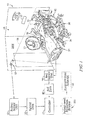
- FIG. 1 A first embodiment of a patient-need prediction system 10 in accordance with the present disclosure is shown in Figs. 1 and 2 .
- FIG. 5 A second embodiment of a patient-need prediction system 110 in accordance with the present disclosure is shown in Fig. 5 .
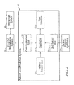
- Both patient-need prediction systems 10, 110 include a controller 14, 114 configured to executed a patient-need prediction process 200 as shown in Fig. 4 .
- the patient-need prediction system 10, 110 receives data from one or more sources and determines a probability that a patient 11 will have a need in a near term, for example, to use a toilet 13 included in a patient room 24. If the patient is predicted to have a near-term need, process 200 may execute a predetermined action so as to minimize risks associated with the patient's need as suggested in Fig. 4 .
- the patient-need prediction system 10 includes a patient sensor unit 12 and the controller 14 as shown, for example, in Figs. 1 and 2 .
- the patient sensor unit 12 is positioned to lie in spaced-apart relation to the patient 11 to detect electromagnetic radiation from a field 16 of view in which the patient 11 is located.
- the patient sensor unit 12 then converts the detected electromagnetic radiation into a patient sensor signal which is indicative of patient data 18 as shown in Fig. 1 .
- the patient sensor signal is then communicated to the controller for processing to predict if the patient 11 will have near-term need.
- the patient sensor unit 12 is coupled to a wall 24W of a patient room in spaced-apart relation to the patient 11.
- the patient sensor unit 12 may communicate with the controller 14 via a wired connection or a wireless connection.
- the patient sensor unit 12 includes a camera configured to detect visible electromagnetic radiation.
- the patient sensor unit 12 includes an infrared camera configured to detect infrared electromagnetic radiation.
- the patient sensor unit 12 includes both a camera and an infrared camera.
- the controller 14 is coupled to the patient sensor unit 12 to receive the patient sensor signal as suggested in Fig. 1 .
- the controller 14 may be located in spaced-apart relation to the patient 11 or included in a patient support apparatus 20 which supports the patient 11.
- the controller 14 is coupled to the patient support apparatus 20 to command the patient support apparatus to perform one or more predetermined actions in response to receiving and processing the patient sensor signal.
- the patient sensor unit 12 may sense a change in a characteristic of the patient 11 which is predictive a patient's 11 need to perform a toileting activity (urinate or defecate) within a future time period.
- the controller 14 performs a predetermined action 22 as suggested in Fig. 1 .
- the predetermined action 22 is, for example, to turn on a light 25 in a patient room 24.
- the patient-need prediction system 10 may predict patient need before the patient 11 is even aware that they will have a need.
- the future time period may be as long as several minutes into the future.
- the patient-need prediction system 10 may determine that the patient 11 will have need to perform a toileting activity while the patient 11 may still be sleeping.
- the patient sensor unit 12 is configured to detect the patient's physiological response to a need to perform a toilet activity even when the patient 11 is non conscious. This need may be manifested as a stress indicator.
- indicators of stress include, but are not limited to, increased blood flow to the face, neck, and/or hands that may be characterized as flushing; increased skin temperature; involuntary or brief facial expressions; increased heart rate; increased blood pressure; and increased perspiration.
- the patient-need prediction system 10 is capable of identifying times of patient stress indicative of a patient need or a near future patient need. Upon evaluation, a pattern of physiological responses is recognizable such that a need, such as a need to toilet, can be identified along with the urgency of that need.
- the patient-need prediction system 10 further includes a communication link 26 as shown in Fig. 2 .
- the communication link 26 is coupled to the controller 14 and configured to provide communication between the controller 14 and a hospital information system 28.
- the hospital information system 28 includes, for example, a centralized nurse call system 30 and a centralized electronic medical record system.
- Both the nurse call system 30 and electronic medical records system include information that is related to the patient support apparatus 20 and associated with the patient 11 stored in memory as related records.
- the information related to the patient 11 stored in memory in the nurse call system 30 and electronic medical records system is constantly updated as information is added to the electronic medical records system and the nurse call system 30 receives information related to the patient 11, the patient support apparatus 20, and the patient-need prediction system 10.
- the patient-need prediction system 10 may communicate the predicted need to the hospital information system 28 via the communication link 26.
- the hospital information system 28 in turn stores the event in the patient's electronic medical record.
- the hospital information system 28 requests that a caregiver come to the patient 11 to help with the predicted patient need.
- the patient 11, as shown in Fig. 1 is supported on the patient support apparatus 20.
- the patient support apparatus 20 includes a support frame 32, a patient support surface 34, and one or more side rails 36. Together the support frame 32, the patient support surface 34, and the side rails 36 cooperate to maximize patient comfort and patient safety.
- the patient support surface 34 is coupled to the support frame 32 and located between the patient 11 and the support frame 32 to maximize patient comfort and minimize skin damage of the patient 11.
- the side rails 36 are coupled to the support frame 32 to move between lowered positions and raised positions. The lower positions are associated with the providing patient care or patient ingress and egress. The raised positions are associated with blocking patient ingress and egress.
- the patient-need prediction system 10 further includes a bed sensor unit 38 as suggested in Fig. 1 and shown in Fig. 2 .
- the bed sensor unit 38 is coupled to the patient support apparatus 20 and configured to provide a bed sensor signal to the controller 14.
- the bed sensor signal is indicative of bed data 40 as shown in Fig. 1 .
- Bed data may include, for example, an arrangement of the support frame 32, a status of the patient support surface 34, and the positions of the side rails 36.
- the controller 14 receives the bed sensor signal and uses the bed data to improve a prediction of patient need.
- the controller 14 may also use the bed data to determine a risk of falling for the patient 11 which may alter the predetermined action performed by the controller 14.
- the controller 14 may also receive data from the hospital information system 28 which may affect the prediction of patient need and evaluation of risk of falling as suggested in Fig. 4 .
- the patient-need prediction system 10 may further include a user interface 42.
- the user interface 42 is coupled to the controller 14 and configured to provide input data to the controller 14 and receive commands from the controller 14.
- the controller 14 may have predicted that the patient 11 will need help with a toileting activity.
- the controller 14 then commands the user interface 42 to display a message to the patient 11 communicating that the caregiver has been summoned to help the patient.
- the controller 14 may also command the user interface 42 to provide an audio communication to the patient 11 that the caregiver has been summoned.
- the caregiver engages the user interface 42 to let the controller 14 know the caregiver has arrived.
- the patient sensor unit 12 may see that a caregiver has arrived and communicate the information to the controller 14.
- a sensor included in the patient support apparatus 20 may determined that the caregiver has arrived and communicate the information to the controller 14.
- the caregiver may request data from the hospital information system 28 using the user interface 42.
- the controller 14 receives the request from the user interface 42, obtains data from the hospital information system 28, and displays the data on the user interface 42 for the caregiver.
- the controller 14 may also receive other information from the hospital information system 28 which may be useful in the analysis of predicting future patient need.
- the controller 14 includes a processor 14A, memory 14B, one or more inputs 14C, and one or more outputs 14D as shown in Fig. 3 .
- Sensor information may be received by processor 14A via inputs 14C and stored in memory 14B.
- processor 14A may execute various processes, for example, the process 200.
- the processor 14A issues various commands via outputs 14D.
- the processor 14A commands to the communication link 26 to summon a caregiver via the hospital information system 28.
- Outputs 14D of controller 14 may be coupled to actuators, blowers, equipment in the patient room 24, etc. to control various equipment and processes included in the patient-need prediction system 10 and patient support apparatus 20.
- the processor 14A may store information received from inputs 14C in memory 14B for additional processing, collection of additional data, or communication of data to the hospital information system 28.
- the controller 14 includes a power supply 14F.
- the power supply 14F may be a battery which supplies power to the processor 14A.
- the power supply 14F may also be a wire which is coupled to a power supply included in the patient support apparatus 20.
- the power supply 14F may also include a transformer which provides power from the patient support apparatus 20 or an electrical wall socket to the processor 14A at an appropriate voltage and frequency.
- the controller 14 receives sensor signals from the patient sensor unit 12 as shown in Fig. 2 .
- the processor 14A of the controller 14 executes instructions stored in memory 14B to perform the process 200 as shown in Fig. 4 .
- the process 200 begins with an operation 202 which captures patient data obtained from the patient sensor signal provided by the patient sensor unit 12.
- the process 200 then proceeds to an operation 204 in which the processor 14A evaluates the patient data.
- the processor 14A examines the patient data over time to look for differences in the patient data that may be predictive of patient stress or need.
- the processor 14A compares a patient's facial expressions at a first time to a patient's facial expressions at a later second time.
- the controller 14 looks for micro-expressions (brief involuntary facial expressions) that are predictive of patient stress or need.
- the processor 14A compares a thermal image of the patient at a first time to a thermal image of the patient at a later second time.
- the controller 14 looks for increases in temperature of the patient that indicative of blushing as provided by increased blood flow to the face, neck, and hands which may be predictive of patient stress or need.
- Other objective physiological responses which may be monitored by the patient sensor unit 12 includes increased skin temperature, increased heart rate, increased blood pressure, and increased perspiration.
- the controller 14 may retrieve information from the hospital information system 28 about medication or therapy administered to the patient 11. Such information may be used by the controller 14 to modify the analysis to take into account patient treatment information.
- the process 200 includes optional operations that may be executed in parallel with the operations 202 and 204.
- the process 200 includes an operation 206 in which the processor 14A captures bed data obtained from the bed sensor signal provided by the bed sensor unit 38.
- the process 200 then proceeds to an operation 208 in which the processor 14A evaluates the bed data.
- the processor 14A examines the bed data for use in improving prediction of patient need and in predicting risk of fall for the patient 11.
- the bed data may also include data obtained from the hospital information system 28.
- the processor 14A evaluates an orientation of the support frame 32. If the support frame 32 is in a raised position, the risk of fall or injury from a fall is increased. If the support frame 32 is a lowered position, the risk of fall or injury is reduced as the patient has less distance to fall before impacting the floor. In another example of operation 208, the processor 14A evaluates a position of the side rails 36. If one or more of the side rails 36 are lowered, then the ability of the patient 11 to exit the patient support apparatus 20 is increased. If all of the side rails 36 are raised, then the ability of the patient 11 to exit the patient support apparatus 20 is decreased. Reference is hereby made to U.S. Provisional Patent Application No. 61/610,663, filed March 14, 2012 and titled ALGORITHM FOR PREDICTING AND MITIGATING ADVERSE EVENTS for disclosure relating to additional data, factors, and information pertaining to mitigating adverse events.
- the process 200 proceeds to an operation 210 as shown, for example, in Fig. 4 .
- the processor 14A uses the evaluations performed during operations 204, 208 to determine a probability of patient need in a predetermined future time period.
- the probability may be expressed in terms of a percentage value.
- the processor may calculate the probability by adding up various components where each component is a value provided during the operations 204, 208 and multiplied by a weighing factor according to correlation or relationship to known patient need or stress.
- a probability of 100% indicates that the patient 11 is undergoing stress and is in immediate need of help from a caregiver.
- the stress may result from a full bladder and an immediate need to perform a toileting function.
- a probability of less than 50% indicates that the patient 11 is undergoing stress and may have need of help from a caregiver in the future.
- the operation 210 may also include a cost/benefit factor which provides for a cost/benefit analysis.
- the cost/benefit analysis weighs the burden of performing a predetermined action in the operation 216 with the benefits of early intervention. The performance of too many predetermined actions may lead to alarm fatigue resulting in caregivers not trusting the patient-need prediction system.
- the cost/benefit factor may change the overall threshold by examining other factors such as the likelihood of fall for the patient, risk for skin damage, etc. For some patients, caregivers may desire more false alarms because the risk to the patient of falling, for example, may outweigh some false alarms.
- the process 200 then proceeds to a decision operation 214 as shown in Fig. 4 .
- the decision operation 214 determines whether the probability calculated in the decision operation 210 has exceeded a predetermined threshold.
- the predetermined threshold may be a generic value set for all patients. However, the predetermined threshold may be a customized value specific to each patient. Furthermore, the predetermined value may be set according to factors associated with risk of incontinence or fall associated with each patient.
- the predetermined threshold may also be changed from time to time by the controller 14 in response to feedback provided by the bed sensor unit 38, the patient sensor unit 12, and the user interface 42. In this example, the threshold value may be changed as a result of making a prediction and determining that the prediction was either right or wrong. In another example, the threshold value may be changed after the controller 14 observes a known stress event and leans from the event to determine specific changes in the patient that was observed so that the threshold value is customized to a specific patient.
- the process 200 returns to operations 202 and 206 to capture additional patient and bed data. If the decision operation 214 determines that the probability threshold was exceeded, the process proceeds to an operation 216 in which controller 14 commands one or more predetermined actions to occur as shown in Fig. 4 .
- the predetermined action includes the controller 14 commanding the communication link 26 to request that a caregiver come to help the patient 11 via the hospital information system 28 and the nurse call system 30.
- the predetermined action may further include the controller 14 commanding the user interface 42 to provide a notification to the patient 11 that a caregiver has been summoned to help the patient 11.
- the process 200 also includes optional operations 218, 220 which may be performed if the optional operations 206, 208 related to bed data are performed. As shown in Fig. 4 , the process 200 may proceed from the decision operation 214 if the probability threshold is exceeded to the operation 218.
- the operation 218 uses the evaluated bed data and evaluated patient data provided by the operations 204, 208 to determine a probability of fall for the patient 11. The probability may be expressed in terms of a percentage value.
- the processor may calculate the probability by adding up various components where each component is a value provided during the operations 204, 208 and multiplied by a weighing factor according to correlation or relationship to known patient risk of fall. In one example, a probability of 100% indicates that the patient 11 will fall if left to exit the patient support apparatus 20 without help from a caregiver. A probability of less than 50% indicates that the patient 11 is unsteady and may fall but is unlikely to fall.
- the process 200 then proceeds to a decision operation 220 as shown in Fig. 4 .
- the decision operation 220 determines whether the probability calculated in the decision operation 214 has exceeded a predetermined threshold.
- the predetermined threshold may be a generic value set for all patients. However, the predetermined threshold may be a customized value specific to each patient. Furthermore, the predetermined value may be set according to factors associated with risk of fall associated with each patient.
- the predetermined threshold may also be changed from time to time by the controller 14 in response to feedback provided by the bed sensor unit 38, the patient sensor unit 12, and the user interface 42. In this example, the threshold value may be changed as a result of making a prediction and determining that the prediction was either right or wrong.
- the process 200 returns to operations 202 and 206 to capture additional patient and bed data. If the decision operation 220 determines that the probability threshold was exceeded, the process proceeds to the operation 216 in which controller 14 commands one or more predetermined actions to occur as shown in Fig. 4 .
- the predetermined action includes the controller 14 commanding the communication link 26 to request that a caregiver come to help the patient 11 via the hospital information system 28 and the nurse call system 30, commanding the user interface 42 to provide a notification to the patient 11 that a caregiver has been summoned to help the patient 11, and commanding that a siderail lock engage locking the side rails 36 in the raised position blocking the patient from exiting the patient support apparatus 20 until a caregiver arrives.
- the risk of an incontinence event may be preferred to the risk of fall.
- the controller 14 took the above described predetermined action as a result of the controller 14 examining several factors. First, the controller 14 determined that the probability threshold for patient need was exceeded and that that patient would likely attempt to the exit the patient support apparatus 20 for a toileting activity in a near future time frame. Second, the controller 14 also determined that the fall probability threshold was exceeded and that the patient was likely to fall if allowed to exit the patient support apparatus 20 without help from a caregiver. As a result, the controller 14 issued a command to block exit from the patient support apparatus 20 so that risk of fall could be minimized.
- the controller 14 may also communicate with an environmental systems controller (not shown) which provides an interface between the patient-need prediction system 10 and various environmental systems including lights, heating-ventilating-air-conditioning system, and entertainment devices such as a television or radio, for example.
- the environmental systems controller may provide information to the controller 14 and act on instructions received from the controller 14 to modify operation of the environmental systems as part of the operation 216. Some of the information provided by the environmental systems controller is stored in memory associated with the environmental systems controller. The information provided by the environmental systems controller is updated as operating parameters of the environmental systems change.
- the controller 14 may issue commands to the environmental systems controller as part of the operation 216 to perform a predetermined action.
- the controller 14 may also be in communication with one or more peripheral devices positioned in the patient room 24.
- the peripheral devices each perform a therapy or diagnostic function.
- the peripheral device may be a ventilator, heart monitor, blood pressure monitor, infusion device, blood oxygen monitor, sequential compression device, high-frequency chest wall oscillation device, or another standalone diagnostic or therapeutic device.
- Information used by the controller 14 may be stored in memory associated with a peripheral device, including the therapy parameters or current operating conditions of the peripheral device.
- diagnostic values such as a heart rate, blood pressure, or other diagnostic values may be stored in memory associated with the peripheral device.
- the peripheral devices may communicate to the controller 14 via a network connection such as a controller area network (CAN) and information stored on a controller of the device may be accessible by the controller.
- CAN controller area network
- the information may be stored by the hospital information system 28.
- the peripheral devices may communicate with the controller 14 and the controller 14 may store information related to the operator of the peripheral device(s) in memory 14B of the controller 14. Any number of peripheral devices may be in communication with the patient-need prediction system 10. It should be understood that peripheral devices may be in direct communication with the hospital information system 28 without being connected through the patient-need prediction system 10 or the patient support apparatus 20.
- the controller 14 may use data obtained from the peripheral devices to improve the operations 204, 208 so that improved predictions may occur.
- the nurse call system 30 generates alarms and notifies caregivers of alarm conditions based on signals from the controller 14 of the patient-need prediction system 10.
- the user interface 42 of the patient-need prediction system 10 may be used to provide communication, such as audio or video communications, between the patient 11 and a nurse positioned at a central nurse call station.
- Caregivers may also carry communication badges that include telephone or other voice communication capability, with the badges providing a direct communication between the caregiver and the central nurse call station or the patient 11, such as the system disclosed in U.S. Pat. No. 7,746,218 titled CONFIGURABLE SYSTEMS FOR ALERTING CAREGIVERS.
- the nurse call system and/or communication badges may facilitate direct communication between a caregiver and the patient 11 located in the care facility. In this way, the nurse call system 30 acts as a dispatch system to provide instructions to caregivers when the controller 14 issues commands as part of the operation 216.
- the process 200 returns to the operations 202, 206. There, the process 200 starts over and data from the patient sensor unit 12 and the bed sensor unit 38 is collected.
- the patient-need prediction system 110 includes the patient sensor unit 12 and a patient support apparatus 120.
- the patient support apparatus 120 includes a controller 114, a communication link 126, a user interface 142, a bed sensor unit 138, the support frame 32, and patient support surface 34 as well as other equipment.
- the patient support apparatus 120 provides the bed sensor unit 138, the controller 114, the user interface 142, and the communication link 126.
- the bed sensor unit 138, the controller 114, the user interface 142, and the communication link 126 function substantially the same as discussed above and will not be discussed in detail.
- the controller 114 is configured to execute the process 200 as described above.
- the controller 114 is able to integrate the bed sensor signal provided by the bed sensor unit 138 as the bed sensor unit 138 is included in the patient support apparatus 120.
- all sensor included in the patient support apparatus may be part of the bed sensor unit 138 and have sensor signals included in the bed sensor signal.
- any sensor data available from the patient support apparatus 20 is available to the patient-need prediction system 110.
- the controller 14 of the patient support apparatus 120 includes inputs 14C that provide information to the processor 14A.
- These inputs 14C may be one or more sensors included in the patient support apparatus 120.
- frame position sensors, siderail position sensors, support surface sensors, a scale system, and caster brake sensors are all in communication with the controller 14.
- the frame position sensors provide information regarding the position of various components of the patient support apparatus 120. Information provided may include the height of the patient support apparatus, the inclination of a head section of the support frame 32, the degree of tilt of an upper frame included in the support frame, or any other frame position data that might be available from frame position sensors of the particular patient support apparatus 120.
- the side rail position sensors provide an indication to the controller 14 of whether a particular side rail 36 of the patient support apparatus 120 is in a raised or lowered position. It is contemplated that additional sensors may be implemented which indicate whether a particular side rail is latched into a particular position.
- the patient support apparatus 120 may includes siderail actuators, siderail locks, and caster brake actuators which are each controlled by the controller 14.
- the patient support apparatus 120 may include motorized side rails such as those disclosed in U.S. Patent Application Publication No. US 2009/0229051 , titled SIDERAIL FOR A PATIENT-SUPPORT APPARATUS.
- the patient support apparatus 120 may also include locking side rails that include an electromechanical lock, such as those disclosed in U.S. Patent No.
- the siderail actuators are operable to move the siderails between raised and lowered positions.
- the siderail locks are operable to lock the siderail in a given position.
- the caster brake actuators are operable to activate the caster brake system.
- the caster brake actuators may actuate a locking mechanism.
- the structures disclosed in U.S. Pat. No. 7,690,059 titled HOSPITAL BED or 7,200,894 titled ROLLER disclose suitable locking mechanisms.
- the controller 14 may command one or more pieces of the above discussed equipment to engage or disengage as part of a predetermined action during the operation 216.
- the support surface sensors provide information regarding the operation of the patient support surface 34, such as an inflatable/pneumatic mattress, of the patient support apparatus 120.
- a patient support surface 34 may be integrated into the support frame 32 of the patient support apparatus 120 or may be a separate structure that is operated generally independently of the patient support apparatus 120, but communicates with the controller 14 of the patient support apparatus 120.
- the support surface sensors may include pressure sensors that identify pressures in particular inflatable structures of the support surface or they may include position sensors. For example, accelerometers positioned in particular locations within the patient support surface 34 may provide feedback regarding the amount of inclination of a particular section of the patient support surface 34 relative to gravity, independent of the frame position sensors. The support surface sensors may also provide information regarding the degree of lateral rotation of a patient supported on the support surface.
- the patient support apparatus 120 may include a support surface pressure control system which is operable to control the pressure in one or more air bladders in the patient support surface 34. Information from the support surface sensors may be included in the bed sensor signal and used to improve determination of probabilities during the operations 210, 218.
- the scale system provides information to the controller 14 regarding the weight of the patient supported on the patient support apparatus 120.
- the scale system also provides information regarding the position of a patient on the patient support apparatus 120 and may provide information regarding the degree of movement of the patient.
- Such a system is disclosed in U.S. Pat. Nos. 5,276,432 titled PATIENT EXIT DETECTOR MECHANISM FOR HOSPITAL BED or 7,437,787 titled LOAD-CELL BASED HOSPITAL BED CONTROL.
- the data from the scale system may also be used by the controller 14 to determine if an unexpected weight has been added to the patient support apparatus 120 or provide other data regarding activities around the patient support apparatus 120. For example, in an approach disclosed in U.S. Published Pat. Application No.
- the support surface sensors and the scale system cooperate to provide data regarding the position of a patient supported on the patient support apparatus 120.
- the support surface sensors and scale system may cooperate to determine that a patient is sitting up on a patient support apparatus 120 without having the head section raised as disclosed in U.S. Published Pat. Application No. 2008/0189865 .
- Such information may be useful during the operation 218 to help determine the probability of bed exit by the patient 11.
- the caster brake sensors provide information to the controller 14 regarding the position of the brakes on the patient support apparatus 120. For example, casters should be in a locked position to prevent the patient support apparatus 120 from rolling as the patient 11 attempts to exit the patient support apparatus 120.
- activation or deactivation of the caster brake sensors may provide an indication of the presence of a caregiver in the patient room 24 at a particular time. Activation of other caregiver controls may be considered to identify the presence of a caregiver in the patient room 24 when the controls are activated on the user interface 42.
- the patient support apparatus 120 may include other sensors that provide information to the controller 14 regarding the status of portions of the patient support apparatus 120 and the sensors discussed herein are examples only.
- information that is related to the patient 11 is considered to be physiological information, data items, or factors. This may include diagnostic or therapy information from a peripheral device, diagnoses or physical characteristics available from the hospital information system 28, including medications being taken or therapies being received, or patient specific information as detected by the scale system or support surface sensors.
- Information related to the patient support apparatus 120 is considered to be patient support apparatus information, data items, or factors. These include the positions of members or components of the patient support apparatus 120, the type of patient support apparatus, the status of patient support apparatus functions such as a caster lock or siderail lock.
- Information related to the environment as determined and controlled by the environmental system is considered to be environmental information, data items, or factors. This may include the status of various environmental equipment including room temperature, the status of lighting, the status of entertainment devices or other similar information.
Applications Claiming Priority (1)
| Application Number | Priority Date | Filing Date | Title |
|---|---|---|---|
| US14/250,848 US9311804B2 (en) | 2014-04-11 | 2014-04-11 | Patient-need prediction system |
Publications (3)
| Publication Number | Publication Date |
|---|---|
| EP2930637A2 true EP2930637A2 (de) | 2015-10-14 |
| EP2930637A3 EP2930637A3 (de) | 2017-11-15 |
| EP2930637B1 EP2930637B1 (de) | 2021-03-10 |
Family
ID=53268586
Family Applications (1)
| Application Number | Title | Priority Date | Filing Date |
|---|---|---|---|
| EP15162821.1A Active EP2930637B1 (de) | 2014-04-11 | 2015-04-08 | Verfahren zur vorhersage von patientenbedürfnissen |
Country Status (2)
| Country | Link |
|---|---|
| US (3) | US9311804B2 (de) |
| EP (1) | EP2930637B1 (de) |
Cited By (2)
| Publication number | Priority date | Publication date | Assignee | Title |
|---|---|---|---|---|
| CN108447556A (zh) * | 2018-04-11 | 2018-08-24 | 祁智 | 病房护理报警管理系统 |
| US10463294B2 (en) | 2016-12-29 | 2019-11-05 | Hill-Rom Services, Inc. | Video monitoring to detect sleep apnea |
Families Citing this family (20)
| Publication number | Priority date | Publication date | Assignee | Title |
|---|---|---|---|---|
| US7690059B2 (en) * | 2005-12-19 | 2010-04-06 | Stryker Corporation | Hospital bed |
| US9311804B2 (en) * | 2014-04-11 | 2016-04-12 | Hill-Rom Services, Inc. | Patient-need prediction system |
| USD771259S1 (en) * | 2015-01-29 | 2016-11-08 | Hill-Rom Services, Inc. | Foot rail for patient bed |
| EP3205268B1 (de) | 2016-02-11 | 2023-10-25 | Hill-Rom Services, Inc. | Krankenhausbett |
| US10489661B1 (en) | 2016-03-08 | 2019-11-26 | Ocuvera LLC | Medical environment monitoring system |
| US10770177B2 (en) * | 2016-08-08 | 2020-09-08 | Yair Zuckerman | Dispatch management platform for nurse call system |
| US20180146906A1 (en) * | 2016-11-29 | 2018-05-31 | Hill-Rom Services, Inc. | System and method for determining incontinence device replacement interval |
| US10600204B1 (en) | 2016-12-28 | 2020-03-24 | Ocuvera | Medical environment bedsore detection and prevention system |
| US10973720B2 (en) | 2017-04-07 | 2021-04-13 | Hill-Rom Services, Inc. | Image based monitoring of the state of a device |
| JP6514810B2 (ja) * | 2017-05-30 | 2019-05-15 | 花王株式会社 | 介護スケジュール提案装置 |
| CN108294879A (zh) * | 2018-01-22 | 2018-07-20 | 浙江新丰医疗器械有限公司 | 一种重症患者护理床 |
| US11253079B1 (en) | 2018-03-26 | 2022-02-22 | Dp Technologies, Inc. | Multi-zone adjustable bed with smart adjustment mechanism |
| JP7089953B2 (ja) * | 2018-06-15 | 2022-06-23 | パラマウントベッド株式会社 | 支援システム |
| EP3649924A1 (de) * | 2018-11-12 | 2020-05-13 | Koninklijke Philips N.V. | Schmerzlinderung beim patiententransfer |
| KR102295758B1 (ko) * | 2019-08-19 | 2021-08-31 | 김한수 | 요양 서비스 제공 시스템 및 요양 서비스 제공 방법 |
| CN114667574A (zh) * | 2019-10-18 | 2022-06-24 | 梅西莫股份有限公司 | 用于患者监测的显示布局和交互式对象 |
| US11903746B2 (en) * | 2020-06-25 | 2024-02-20 | Hill-Rom Services, Inc. | Incontinence prediction systems and methods |
| EP4023146A1 (de) | 2020-12-30 | 2022-07-06 | Hill-Rom Services, Inc. | Berührungsloses patientenüberwachungssystem mit automatischer bildverbesserung |
| US11882366B2 (en) | 2021-02-26 | 2024-01-23 | Hill-Rom Services, Inc. | Patient monitoring system |
| CN113287805A (zh) * | 2021-05-27 | 2021-08-24 | 郑州大学 | 一种跌倒防护方法及可穿戴式跌倒防护装置 |
Citations (7)
| Publication number | Priority date | Publication date | Assignee | Title |
|---|---|---|---|---|
| US5276432A (en) | 1992-01-15 | 1994-01-04 | Stryker Corporation | Patient exit detection mechanism for hospital bed |
| US7200894B2 (en) | 2001-01-12 | 2007-04-10 | Tente-Rollen Gmbh & Co.Kg | Roller |
| US20080189865A1 (en) | 2005-07-26 | 2008-08-14 | Hill-Rom Services, Inc. | System and Method for Controlling an Air Mattress |
| US7437787B2 (en) | 2004-08-09 | 2008-10-21 | Hill-Rom Services, Inc. | Load-cell based hospital bed control |
| US20090229051A1 (en) | 2008-03-13 | 2009-09-17 | Hill-Rom Services, Inc. | Siderail assembly for a patient-support apparatus |
| US7690059B2 (en) | 2005-12-19 | 2010-04-06 | Stryker Corporation | Hospital bed |
| US7746218B2 (en) | 2004-08-02 | 2010-06-29 | Hill-Rom Services, Inc. | Configurable system for alerting caregivers |
Family Cites Families (93)
| Publication number | Priority date | Publication date | Assignee | Title |
|---|---|---|---|---|
| US3972320A (en) | 1974-08-12 | 1976-08-03 | Gabor Ujhelyi Kalman | Patient monitoring system |
| US4196425A (en) | 1978-07-10 | 1980-04-01 | by said David S. Weekly said Clyde E. Williams | Patient activity monitoring system |
| US4539560A (en) | 1982-12-10 | 1985-09-03 | Hill-Rom Company, Inc. | Bed departure detection system |
| US4633237A (en) | 1984-07-11 | 1986-12-30 | Kenneth A. Tucknott | Patient bed alarm system |
| US4947152A (en) | 1986-02-10 | 1990-08-07 | Mesa Vista Hospital | Patient monitoring system |
| US4814751A (en) | 1987-02-27 | 1989-03-21 | Wildlife Materials, Inc. | Patient tracking system |
| US4952928A (en) | 1988-08-29 | 1990-08-28 | B. I. Incorporated | Adaptable electronic monitoring and identification system |
| US4907845A (en) | 1988-09-16 | 1990-03-13 | Salomon Sa | Bed patient monitoring system |
| US5107854A (en) | 1989-05-19 | 1992-04-28 | Boulder Impact Monitors, Inc. | Orthopedic limb load monitor |
| US5008654A (en) | 1989-11-07 | 1991-04-16 | Callaway James J | Patient ambulation motion detector |
| US6958706B2 (en) | 1990-07-27 | 2005-10-25 | Hill-Rom Services, Inc. | Patient care and communication system |
| US5594786A (en) | 1990-07-27 | 1997-01-14 | Executone Information Systems, Inc. | Patient care and communication system |
| US5218344A (en) | 1991-07-31 | 1993-06-08 | Ricketts James G | Method and system for monitoring personnel |
| US5365217A (en) | 1992-02-20 | 1994-11-15 | Frank J. Toner | Personal security system apparatus and method |
| US5353012A (en) | 1992-05-14 | 1994-10-04 | Bartronix, Inc. | Bed position and activity sensing apparatus |
| WO1994000817A1 (en) | 1992-06-22 | 1994-01-06 | Health Risk Management, Inc. | Health care management system |
| US5416695A (en) | 1993-03-09 | 1995-05-16 | Metriplex, Inc. | Method and apparatus for alerting patients and medical personnel of emergency medical situations |
| US5495288A (en) | 1994-01-28 | 1996-02-27 | Ultrak, Inc. | Remote activated surveillance system |
| EP0671145B1 (de) | 1994-03-09 | 1999-05-19 | John Alan Hall Jackson | Fühler-Vorrichtung für ein Bett und Bett mit Fühler-Vorrichtung |
| US5738102A (en) | 1994-03-31 | 1998-04-14 | Lemelson; Jerome H. | Patient monitoring system |
| US5714931A (en) | 1994-05-16 | 1998-02-03 | Petite; Thomas D. | Personalized security system |
| US5633627A (en) | 1994-09-23 | 1997-05-27 | Bed-Check Corporation | Hard-wired monitoring system for hospital bed or short term care patients |
| US5519380A (en) | 1994-11-04 | 1996-05-21 | Guardian Electronics, Inc. | Personal monitoring system and method |
| US5946659A (en) | 1995-02-28 | 1999-08-31 | Clinicomp International, Inc. | System and method for notification and access of patient care information being simultaneously entered |
| US6671563B1 (en) | 1995-05-15 | 2003-12-30 | Alaris Medical Systems, Inc. | System and method for collecting data and managing patient care |
| US5781442A (en) | 1995-05-15 | 1998-07-14 | Alaris Medical Systems, Inc. | System and method for collecting data and managing patient care |
| US6125350A (en) | 1995-06-02 | 2000-09-26 | Software For Surgeons | Medical information log system |
| US5740800A (en) | 1996-03-01 | 1998-04-21 | Hewlett-Packard Company | Method and apparatus for clinical pathway order selection in a medical information system |
| US5831699A (en) | 1996-04-29 | 1998-11-03 | Motorola, Inc. | Display with inactive portions and active portions, and having drivers in the inactive portions |
| US5765139A (en) | 1996-04-30 | 1998-06-09 | International Business Machines Corporation | Method and apparatus for transforming a resource planning data structure into a scheduling data structure |
| DE69736622T2 (de) | 1996-07-03 | 2007-09-13 | Hitachi, Ltd. | System zur Bewegungserkennung |
| US5877675A (en) | 1996-08-29 | 1999-03-02 | Jansys, Inc. | Wireless healthcare communication system |
| US6067019A (en) | 1996-11-25 | 2000-05-23 | Hill-Rom, Inc. | Bed exit detection apparatus |
| US6624754B1 (en) | 1998-01-20 | 2003-09-23 | Hoffman Resources Llc | Personal security and tracking system |
| US5844488A (en) | 1997-09-23 | 1998-12-01 | Musick; Jeff L. | Bed sensor and alarm |
| US6466125B1 (en) | 1998-03-23 | 2002-10-15 | Time Domain Corporation | System and method using impulse radio technology to track and monitor people needing health care |
| US6154139A (en) | 1998-04-21 | 2000-11-28 | Versus Technology | Method and system for locating subjects within a tracking environment |
| US6169484B1 (en) | 1998-04-28 | 2001-01-02 | Itt Manufacturing Enterprises, Inc. | Personal location system |
| US6049281A (en) | 1998-09-29 | 2000-04-11 | Osterweil; Josef | Method and apparatus for monitoring movements of an individual |
| US6160478A (en) | 1998-10-27 | 2000-12-12 | Sarcos Lc | Wireless health monitoring system |
| US6078261A (en) | 1998-11-10 | 2000-06-20 | Alert Systems, Inc. | System for monitoring a bed patient |
| US6791460B2 (en) | 1999-03-05 | 2004-09-14 | Hill-Rom Services, Inc. | Patient position detection apparatus for a bed |
| US6204767B1 (en) | 1999-06-04 | 2001-03-20 | Donald A. Edwards | Chair monitor |
| US6804656B1 (en) | 1999-06-23 | 2004-10-12 | Visicu, Inc. | System and method for providing continuous, expert network critical care services from a remote location(s) |
| US6975230B1 (en) | 1999-07-29 | 2005-12-13 | Arend Jan Brilman | Method and apparatus for registering movement patterns of human beings |
| US6637649B2 (en) | 1999-12-28 | 2003-10-28 | Christopher S. Walsh | Record and verification method, apparatus and system |
| ATE339154T1 (de) | 1999-09-21 | 2006-10-15 | Honeywell Hommed Llc | System zur häuslichen patientenüberwachung |
| US6492904B2 (en) | 1999-09-27 | 2002-12-10 | Time Domain Corporation | Method and system for coordinating timing among ultrawideband transmissions |
| US6640212B1 (en) | 1999-09-30 | 2003-10-28 | Rodney L. Rosse | Standardized information management system for long-term residence facilities |
| US6524239B1 (en) | 1999-11-05 | 2003-02-25 | Wcr Company | Apparatus for non-instrusively measuring health parameters of a subject and method of use thereof |
| US6611783B2 (en) | 2000-01-07 | 2003-08-26 | Nocwatch, Inc. | Attitude indicator and activity monitoring device |
| US6876303B2 (en) | 2000-05-05 | 2005-04-05 | Hill-Rom Services, Inc. | Hospital monitoring and control system and method |
| US20020140559A1 (en) | 2001-03-29 | 2002-10-03 | Zhou Peter Y. | System and method for remotely monitoring |
| US6968294B2 (en) | 2001-03-15 | 2005-11-22 | Koninklijke Philips Electronics N.V. | Automatic system for monitoring person requiring care and his/her caretaker |
| US6611206B2 (en) | 2001-03-15 | 2003-08-26 | Koninklijke Philips Electronics N.V. | Automatic system for monitoring independent person requiring occasional assistance |
| WO2002078513A2 (en) | 2001-03-30 | 2002-10-10 | Augmentech, Inc. | Patient incontinence/position monitoring apparatus and method of use thereof |
| WO2002082348A2 (en) | 2001-04-05 | 2002-10-17 | Instrumentarium Corporation | Method and system for detecting variances in a tracking environment |
| US6748250B1 (en) | 2001-04-27 | 2004-06-08 | Medoptix, Inc. | Method and system of monitoring a patient |
| US7242306B2 (en) | 2001-05-08 | 2007-07-10 | Hill-Rom Services, Inc. | Article locating and tracking apparatus and method |
| JP2003000553A (ja) | 2001-06-25 | 2003-01-07 | Nippon Colin Co Ltd | 患者検知装置 |
| US20030013459A1 (en) | 2001-07-10 | 2003-01-16 | Koninklijke Philips Electronics N.V. | Method and system for location based recordal of user activity |
| US6544200B1 (en) * | 2001-08-31 | 2003-04-08 | Bed-Check Corporation | Electronic patient monitor with automatically configured alarm parameters |
| ATE365337T1 (de) | 2001-09-05 | 2007-07-15 | Newbury Networks Inc | Positionsdetektion und standortverfolgung in einem drahtlosen netzwerk |
| US7369680B2 (en) | 2001-09-27 | 2008-05-06 | Koninklijke Phhilips Electronics N.V. | Method and apparatus for detecting an event based on patterns of behavior |
| US7110569B2 (en) | 2001-09-27 | 2006-09-19 | Koninklijke Philips Electronics N.V. | Video based detection of fall-down and other events |
| US6822571B2 (en) | 2001-11-15 | 2004-11-23 | Stryker Corporation | Patient movement detection system for a bed including a load cell mounting assembly |
| US6853304B2 (en) | 2002-05-07 | 2005-02-08 | Dmatek Ltd. | Monitoring device |
| US6788206B1 (en) | 2002-09-05 | 2004-09-07 | Donald A. Edwards | Patient monitoring system |
| US6909367B1 (en) | 2003-02-24 | 2005-06-21 | Larry P. Wetmore | Method of determining the exact location of an individual in a structure |
| US7071820B2 (en) | 2003-03-19 | 2006-07-04 | Callaway James J | Wireless patient ambulation motion detector and second call system |
| US6838992B2 (en) | 2003-03-21 | 2005-01-04 | Versus Technology, Inc. | Methods and systems for locating subjects and providing event notification within a tracking environment and badge for use therein |
| US6897781B2 (en) | 2003-03-26 | 2005-05-24 | Bed-Check Corporation | Electronic patient monitor and white noise source |
| US6987232B2 (en) | 2003-07-14 | 2006-01-17 | Bed-Check Corporation | Sensor and method for detecting a patient's movement via position and occlusion |
| CA2533508A1 (en) | 2003-07-22 | 2005-02-03 | Ronjo Llc | Method of monitoring sleeping infant |
| US7452336B2 (en) | 2003-09-06 | 2008-11-18 | Interactive Neuro Technology, Inc. | Interactive neural training device |
| DE102004018016A1 (de) | 2004-04-14 | 2005-11-10 | Sick Ag | Verfahren zur Überwachung eines Überwachungsbereichs |
| DE102004021972A1 (de) | 2004-05-04 | 2005-12-01 | Siemens Ag | Patientenliege und Verfahren zur reproduzierbaren Positionierung und Lagerung eines Patienten |
| US7502498B2 (en) | 2004-09-10 | 2009-03-10 | Available For Licensing | Patient monitoring apparatus |
| DE102007011807B3 (de) | 2007-03-12 | 2008-10-23 | Siemens Ag | Sequenz für die Magnet-Resonanz-Bildgebung und Magnet-Resonanz-Gerät hierzu |
| US20080294012A1 (en) * | 2007-05-22 | 2008-11-27 | Kurtz Andrew F | Monitoring physiological conditions |
| KR20090001848A (ko) * | 2007-05-28 | 2009-01-09 | 에스케이 텔레콤주식회사 | 얼굴표정 감시 방법 및 얼굴표정 감시 시스템 |
| US7987069B2 (en) | 2007-11-12 | 2011-07-26 | Bee Cave, Llc | Monitoring patient support exiting and initiating response |
| US7988647B2 (en) | 2008-03-14 | 2011-08-02 | Bunn Frank E | Assessment of medical conditions by determining mobility |
| US8606344B2 (en) | 2008-04-30 | 2013-12-10 | Board Of Regents, The University Of Texas System | Integrated patient bed system |
| BRPI0913517B1 (pt) | 2008-09-04 | 2019-08-20 | Koninklijke Philips N.V. | Sistemas para a prevenção de queda para um usuário, método para prevenção de queda para um usuário, e meio legível por computador não transitório |
| US10438496B2 (en) | 2008-11-18 | 2019-10-08 | Victoria Panzer | Method and system for fall prevention in older adults |
| US20110278459A1 (en) | 2010-05-14 | 2011-11-17 | Sony Corporation | System and method for monitoring the presence of a person in a monitored area |
| US8620625B2 (en) | 2010-07-30 | 2013-12-31 | Hill-Rom Services, Inc. | Above bed sensor |
| US9934427B2 (en) * | 2010-09-23 | 2018-04-03 | Stryker Corporation | Video monitoring system |
| US8907287B2 (en) * | 2010-12-01 | 2014-12-09 | Hill-Rom Services, Inc. | Patient monitoring system |
| US20130127620A1 (en) * | 2011-06-20 | 2013-05-23 | Cerner Innovation, Inc. | Management of patient fall risk |
| US9213956B2 (en) | 2012-03-14 | 2015-12-15 | Hill-Rom Services, Inc. | Algorithm for predicting and mitigating adverse events |
| US9311804B2 (en) | 2014-04-11 | 2016-04-12 | Hill-Rom Services, Inc. | Patient-need prediction system |
-
2014
- 2014-04-11 US US14/250,848 patent/US9311804B2/en active Active
-
2015
- 2015-04-08 EP EP15162821.1A patent/EP2930637B1/de active Active
-
2016
- 2016-04-06 US US15/091,922 patent/US9763576B2/en active Active
-
2017
- 2017-09-15 US US15/705,876 patent/US10172522B2/en active Active
Patent Citations (7)
| Publication number | Priority date | Publication date | Assignee | Title |
|---|---|---|---|---|
| US5276432A (en) | 1992-01-15 | 1994-01-04 | Stryker Corporation | Patient exit detection mechanism for hospital bed |
| US7200894B2 (en) | 2001-01-12 | 2007-04-10 | Tente-Rollen Gmbh & Co.Kg | Roller |
| US7746218B2 (en) | 2004-08-02 | 2010-06-29 | Hill-Rom Services, Inc. | Configurable system for alerting caregivers |
| US7437787B2 (en) | 2004-08-09 | 2008-10-21 | Hill-Rom Services, Inc. | Load-cell based hospital bed control |
| US20080189865A1 (en) | 2005-07-26 | 2008-08-14 | Hill-Rom Services, Inc. | System and Method for Controlling an Air Mattress |
| US7690059B2 (en) | 2005-12-19 | 2010-04-06 | Stryker Corporation | Hospital bed |
| US20090229051A1 (en) | 2008-03-13 | 2009-09-17 | Hill-Rom Services, Inc. | Siderail assembly for a patient-support apparatus |
Cited By (2)
| Publication number | Priority date | Publication date | Assignee | Title |
|---|---|---|---|---|
| US10463294B2 (en) | 2016-12-29 | 2019-11-05 | Hill-Rom Services, Inc. | Video monitoring to detect sleep apnea |
| CN108447556A (zh) * | 2018-04-11 | 2018-08-24 | 祁智 | 病房护理报警管理系统 |
Also Published As
| Publication number | Publication date |
|---|---|
| US9763576B2 (en) | 2017-09-19 |
| US10172522B2 (en) | 2019-01-08 |
| US20150294549A1 (en) | 2015-10-15 |
| US20160213255A1 (en) | 2016-07-28 |
| EP2930637B1 (de) | 2021-03-10 |
| US20180020924A1 (en) | 2018-01-25 |
| EP2930637A3 (de) | 2017-11-15 |
| US9311804B2 (en) | 2016-04-12 |
Similar Documents
| Publication | Publication Date | Title |
|---|---|---|
| US10172522B2 (en) | Patient-need prediction system | |
| US11081221B2 (en) | Method of predicting and mitigating adverse events | |
| US11033233B2 (en) | Patient support apparatus with patient information sensors | |
| US10632033B1 (en) | Bed-based safety protocol control | |
| US7987069B2 (en) | Monitoring patient support exiting and initiating response | |
| US10357185B2 (en) | Person support apparatuses with motion monitoring | |
| US20090044334A1 (en) | Automatically adjusting patient platform support height in response to patient related events | |
| US20150281659A1 (en) | Image transmission or recording triggered by bed event | |
| EP3640950B1 (de) | Patientenpflegesystem für eine heimumgebung | |
| EP3103385A1 (de) | Durch bettereignis ausgelöste bildübertragung oder -aufzeichnung | |
| US20210106478A1 (en) | Techniques for notifying persons within a vicinity of a patient support apparatus of a remote control function | |
| US11890241B2 (en) | Techniques for managing patient therapy protocols | |
| US20220139549A1 (en) | Remote management of patient environment | |
| AU2022304909A1 (en) | Patient video monitoring system |
Legal Events
| Date | Code | Title | Description |
|---|---|---|---|
| PUAI | Public reference made under article 153(3) epc to a published international application that has entered the european phase |
Free format text: ORIGINAL CODE: 0009012 |
|
| AK | Designated contracting states |
Kind code of ref document: A2 Designated state(s): AL AT BE BG CH CY CZ DE DK EE ES FI FR GB GR HR HU IE IS IT LI LT LU LV MC MK MT NL NO PL PT RO RS SE SI SK SM TR |
|
| AX | Request for extension of the european patent |
Extension state: BA ME |
|
| PUAL | Search report despatched |
Free format text: ORIGINAL CODE: 0009013 |
|
| AK | Designated contracting states |
Kind code of ref document: A3 Designated state(s): AL AT BE BG CH CY CZ DE DK EE ES FI FR GB GR HR HU IE IS IT LI LT LU LV MC MK MT NL NO PL PT RO RS SE SI SK SM TR |
|
| AX | Request for extension of the european patent |
Extension state: BA ME |
|
| RIC1 | Information provided on ipc code assigned before grant |
Ipc: G06F 19/00 20110101AFI20171010BHEP |
|
| STAA | Information on the status of an ep patent application or granted ep patent |
Free format text: STATUS: REQUEST FOR EXAMINATION WAS MADE |
|
| 17P | Request for examination filed |
Effective date: 20180514 |
|
| RBV | Designated contracting states (corrected) |
Designated state(s): AL AT BE BG CH CY CZ DE DK EE ES FI FR GB GR HR HU IE IS IT LI LT LU LV MC MK MT NL NO PL PT RO RS SE SI SK SM TR |
|
| STAA | Information on the status of an ep patent application or granted ep patent |
Free format text: STATUS: EXAMINATION IS IN PROGRESS |
|
| 17Q | First examination report despatched |
Effective date: 20190920 |
|
| REG | Reference to a national code |
Ref country code: DE Ref legal event code: R079 Ref document number: 602015066572 Country of ref document: DE Free format text: PREVIOUS MAIN CLASS: G06F0019000000 Ipc: G16H0040600000 |
|
| GRAP | Despatch of communication of intention to grant a patent |
Free format text: ORIGINAL CODE: EPIDOSNIGR1 |
|
| STAA | Information on the status of an ep patent application or granted ep patent |
Free format text: STATUS: GRANT OF PATENT IS INTENDED |
|
| RIC1 | Information provided on ipc code assigned before grant |
Ipc: G16H 40/60 20180101AFI20200914BHEP |
|
| INTG | Intention to grant announced |
Effective date: 20201002 |
|
| RIN1 | Information on inventor provided before grant (corrected) |
Inventor name: RIBBLE, DAVID, LANCE |
|
| GRAS | Grant fee paid |
Free format text: ORIGINAL CODE: EPIDOSNIGR3 |
|
| GRAA | (expected) grant |
Free format text: ORIGINAL CODE: 0009210 |
|
| STAA | Information on the status of an ep patent application or granted ep patent |
Free format text: STATUS: THE PATENT HAS BEEN GRANTED |
|
| AK | Designated contracting states |
Kind code of ref document: B1 Designated state(s): AL AT BE BG CH CY CZ DE DK EE ES FI FR GB GR HR HU IE IS IT LI LT LU LV MC MK MT NL NO PL PT RO RS SE SI SK SM TR |
|
| REG | Reference to a national code |
Ref country code: GB Ref legal event code: FG4D |
|
| REG | Reference to a national code |
Ref country code: AT Ref legal event code: REF Ref document number: 1370723 Country of ref document: AT Kind code of ref document: T Effective date: 20210315 Ref country code: CH Ref legal event code: EP |
|
| REG | Reference to a national code |
Ref country code: IE Ref legal event code: FG4D |
|
| REG | Reference to a national code |
Ref country code: DE Ref legal event code: R096 Ref document number: 602015066572 Country of ref document: DE |
|
| REG | Reference to a national code |
Ref country code: LT Ref legal event code: MG9D |
|
| PG25 | Lapsed in a contracting state [announced via postgrant information from national office to epo] |
Ref country code: LT Free format text: LAPSE BECAUSE OF FAILURE TO SUBMIT A TRANSLATION OF THE DESCRIPTION OR TO PAY THE FEE WITHIN THE PRESCRIBED TIME-LIMIT Effective date: 20210310 Ref country code: HR Free format text: LAPSE BECAUSE OF FAILURE TO SUBMIT A TRANSLATION OF THE DESCRIPTION OR TO PAY THE FEE WITHIN THE PRESCRIBED TIME-LIMIT Effective date: 20210310 Ref country code: FI Free format text: LAPSE BECAUSE OF FAILURE TO SUBMIT A TRANSLATION OF THE DESCRIPTION OR TO PAY THE FEE WITHIN THE PRESCRIBED TIME-LIMIT Effective date: 20210310 Ref country code: GR Free format text: LAPSE BECAUSE OF FAILURE TO SUBMIT A TRANSLATION OF THE DESCRIPTION OR TO PAY THE FEE WITHIN THE PRESCRIBED TIME-LIMIT Effective date: 20210611 Ref country code: BG Free format text: LAPSE BECAUSE OF FAILURE TO SUBMIT A TRANSLATION OF THE DESCRIPTION OR TO PAY THE FEE WITHIN THE PRESCRIBED TIME-LIMIT Effective date: 20210610 Ref country code: NO Free format text: LAPSE BECAUSE OF FAILURE TO SUBMIT A TRANSLATION OF THE DESCRIPTION OR TO PAY THE FEE WITHIN THE PRESCRIBED TIME-LIMIT Effective date: 20210610 |
|
| REG | Reference to a national code |
Ref country code: AT Ref legal event code: MK05 Ref document number: 1370723 Country of ref document: AT Kind code of ref document: T Effective date: 20210310 |
|
| REG | Reference to a national code |
Ref country code: NL Ref legal event code: MP Effective date: 20210310 |
|
| PG25 | Lapsed in a contracting state [announced via postgrant information from national office to epo] |
Ref country code: SE Free format text: LAPSE BECAUSE OF FAILURE TO SUBMIT A TRANSLATION OF THE DESCRIPTION OR TO PAY THE FEE WITHIN THE PRESCRIBED TIME-LIMIT Effective date: 20210310 Ref country code: RS Free format text: LAPSE BECAUSE OF FAILURE TO SUBMIT A TRANSLATION OF THE DESCRIPTION OR TO PAY THE FEE WITHIN THE PRESCRIBED TIME-LIMIT Effective date: 20210310 Ref country code: LV Free format text: LAPSE BECAUSE OF FAILURE TO SUBMIT A TRANSLATION OF THE DESCRIPTION OR TO PAY THE FEE WITHIN THE PRESCRIBED TIME-LIMIT Effective date: 20210310 |
|
| PG25 | Lapsed in a contracting state [announced via postgrant information from national office to epo] |
Ref country code: NL Free format text: LAPSE BECAUSE OF FAILURE TO SUBMIT A TRANSLATION OF THE DESCRIPTION OR TO PAY THE FEE WITHIN THE PRESCRIBED TIME-LIMIT Effective date: 20210310 |
|
| PG25 | Lapsed in a contracting state [announced via postgrant information from national office to epo] |
Ref country code: SM Free format text: LAPSE BECAUSE OF FAILURE TO SUBMIT A TRANSLATION OF THE DESCRIPTION OR TO PAY THE FEE WITHIN THE PRESCRIBED TIME-LIMIT Effective date: 20210310 Ref country code: CZ Free format text: LAPSE BECAUSE OF FAILURE TO SUBMIT A TRANSLATION OF THE DESCRIPTION OR TO PAY THE FEE WITHIN THE PRESCRIBED TIME-LIMIT Effective date: 20210310 Ref country code: EE Free format text: LAPSE BECAUSE OF FAILURE TO SUBMIT A TRANSLATION OF THE DESCRIPTION OR TO PAY THE FEE WITHIN THE PRESCRIBED TIME-LIMIT Effective date: 20210310 Ref country code: AT Free format text: LAPSE BECAUSE OF FAILURE TO SUBMIT A TRANSLATION OF THE DESCRIPTION OR TO PAY THE FEE WITHIN THE PRESCRIBED TIME-LIMIT Effective date: 20210310 |
|
| PG25 | Lapsed in a contracting state [announced via postgrant information from national office to epo] |
Ref country code: SK Free format text: LAPSE BECAUSE OF FAILURE TO SUBMIT A TRANSLATION OF THE DESCRIPTION OR TO PAY THE FEE WITHIN THE PRESCRIBED TIME-LIMIT Effective date: 20210310 Ref country code: RO Free format text: LAPSE BECAUSE OF FAILURE TO SUBMIT A TRANSLATION OF THE DESCRIPTION OR TO PAY THE FEE WITHIN THE PRESCRIBED TIME-LIMIT Effective date: 20210310 Ref country code: ES Free format text: LAPSE BECAUSE OF FAILURE TO SUBMIT A TRANSLATION OF THE DESCRIPTION OR TO PAY THE FEE WITHIN THE PRESCRIBED TIME-LIMIT Effective date: 20210310 Ref country code: PL Free format text: LAPSE BECAUSE OF FAILURE TO SUBMIT A TRANSLATION OF THE DESCRIPTION OR TO PAY THE FEE WITHIN THE PRESCRIBED TIME-LIMIT Effective date: 20210310 Ref country code: PT Free format text: LAPSE BECAUSE OF FAILURE TO SUBMIT A TRANSLATION OF THE DESCRIPTION OR TO PAY THE FEE WITHIN THE PRESCRIBED TIME-LIMIT Effective date: 20210712 Ref country code: IS Free format text: LAPSE BECAUSE OF FAILURE TO SUBMIT A TRANSLATION OF THE DESCRIPTION OR TO PAY THE FEE WITHIN THE PRESCRIBED TIME-LIMIT Effective date: 20210710 |
|
| REG | Reference to a national code |
Ref country code: DE Ref legal event code: R097 Ref document number: 602015066572 Country of ref document: DE |
|
| PG25 | Lapsed in a contracting state [announced via postgrant information from national office to epo] |
Ref country code: LU Free format text: LAPSE BECAUSE OF NON-PAYMENT OF DUE FEES Effective date: 20210408 |
|
| PLBE | No opposition filed within time limit |
Free format text: ORIGINAL CODE: 0009261 |
|
| STAA | Information on the status of an ep patent application or granted ep patent |
Free format text: STATUS: NO OPPOSITION FILED WITHIN TIME LIMIT |
|
| REG | Reference to a national code |
Ref country code: BE Ref legal event code: MM Effective date: 20210430 |
|
| PG25 | Lapsed in a contracting state [announced via postgrant information from national office to epo] |
Ref country code: MC Free format text: LAPSE BECAUSE OF FAILURE TO SUBMIT A TRANSLATION OF THE DESCRIPTION OR TO PAY THE FEE WITHIN THE PRESCRIBED TIME-LIMIT Effective date: 20210310 Ref country code: LI Free format text: LAPSE BECAUSE OF NON-PAYMENT OF DUE FEES Effective date: 20210430 Ref country code: CH Free format text: LAPSE BECAUSE OF NON-PAYMENT OF DUE FEES Effective date: 20210430 Ref country code: AL Free format text: LAPSE BECAUSE OF FAILURE TO SUBMIT A TRANSLATION OF THE DESCRIPTION OR TO PAY THE FEE WITHIN THE PRESCRIBED TIME-LIMIT Effective date: 20210310 Ref country code: DK Free format text: LAPSE BECAUSE OF FAILURE TO SUBMIT A TRANSLATION OF THE DESCRIPTION OR TO PAY THE FEE WITHIN THE PRESCRIBED TIME-LIMIT Effective date: 20210310 |
|
| 26N | No opposition filed |
Effective date: 20211213 |
|
| PG25 | Lapsed in a contracting state [announced via postgrant information from national office to epo] |
Ref country code: SI Free format text: LAPSE BECAUSE OF FAILURE TO SUBMIT A TRANSLATION OF THE DESCRIPTION OR TO PAY THE FEE WITHIN THE PRESCRIBED TIME-LIMIT Effective date: 20210310 |
|
| PG25 | Lapsed in a contracting state [announced via postgrant information from national office to epo] |
Ref country code: IT Free format text: LAPSE BECAUSE OF FAILURE TO SUBMIT A TRANSLATION OF THE DESCRIPTION OR TO PAY THE FEE WITHIN THE PRESCRIBED TIME-LIMIT Effective date: 20210310 Ref country code: IE Free format text: LAPSE BECAUSE OF NON-PAYMENT OF DUE FEES Effective date: 20210408 |
|
| PG25 | Lapsed in a contracting state [announced via postgrant information from national office to epo] |
Ref country code: IS Free format text: LAPSE BECAUSE OF FAILURE TO SUBMIT A TRANSLATION OF THE DESCRIPTION OR TO PAY THE FEE WITHIN THE PRESCRIBED TIME-LIMIT Effective date: 20210710 |
|
| PG25 | Lapsed in a contracting state [announced via postgrant information from national office to epo] |
Ref country code: BE Free format text: LAPSE BECAUSE OF NON-PAYMENT OF DUE FEES Effective date: 20210430 |
|
| PGFP | Annual fee paid to national office [announced via postgrant information from national office to epo] |
Ref country code: FR Payment date: 20230321 Year of fee payment: 9 |
|
| PG25 | Lapsed in a contracting state [announced via postgrant information from national office to epo] |
Ref country code: HU Free format text: LAPSE BECAUSE OF FAILURE TO SUBMIT A TRANSLATION OF THE DESCRIPTION OR TO PAY THE FEE WITHIN THE PRESCRIBED TIME-LIMIT; INVALID AB INITIO Effective date: 20150408 |
|
| PGFP | Annual fee paid to national office [announced via postgrant information from national office to epo] |
Ref country code: GB Payment date: 20230321 Year of fee payment: 9 |
|
| PG25 | Lapsed in a contracting state [announced via postgrant information from national office to epo] |
Ref country code: CY Free format text: LAPSE BECAUSE OF FAILURE TO SUBMIT A TRANSLATION OF THE DESCRIPTION OR TO PAY THE FEE WITHIN THE PRESCRIBED TIME-LIMIT Effective date: 20210310 |
|
| PGFP | Annual fee paid to national office [announced via postgrant information from national office to epo] |
Ref country code: DE Payment date: 20230321 Year of fee payment: 9 |